EP2820386B1 - Sensor port insert apparatus - Google Patents
Sensor port insert apparatus Download PDFInfo
- Publication number
- EP2820386B1 EP2820386B1 EP13708015.6A EP13708015A EP2820386B1 EP 2820386 B1 EP2820386 B1 EP 2820386B1 EP 13708015 A EP13708015 A EP 13708015A EP 2820386 B1 EP2820386 B1 EP 2820386B1
- Authority
- EP
- European Patent Office
- Prior art keywords
- housing
- insert body
- ultrasonic buffer
- cavity
- ring
- Prior art date
- Legal status (The legal status is an assumption and is not a legal conclusion. Google has not performed a legal analysis and makes no representation as to the accuracy of the status listed.)
- Active
Links
- 239000000463 material Substances 0.000 claims description 21
- 230000008878 coupling Effects 0.000 claims description 20
- 238000010168 coupling process Methods 0.000 claims description 20
- 238000005859 coupling reaction Methods 0.000 claims description 20
- 239000012530 fluid Substances 0.000 claims description 19
- 239000013078 crystal Substances 0.000 claims description 11
- 238000003780 insertion Methods 0.000 claims description 5
- 230000037431 insertion Effects 0.000 claims description 5
- 239000007788 liquid Substances 0.000 claims description 3
- 229920002631 room-temperature vulcanizate silicone Polymers 0.000 claims description 2
- 230000000712 assembly Effects 0.000 description 6
- 238000000429 assembly Methods 0.000 description 6
- 230000001070 adhesive effect Effects 0.000 description 4
- 230000006835 compression Effects 0.000 description 4
- 238000007906 compression Methods 0.000 description 4
- 238000011144 upstream manufacturing Methods 0.000 description 4
- 239000000853 adhesive Substances 0.000 description 3
- 239000003292 glue Substances 0.000 description 3
- 239000007789 gas Substances 0.000 description 2
- 239000004593 Epoxy Substances 0.000 description 1
- 230000005540 biological transmission Effects 0.000 description 1
- 230000008020 evaporation Effects 0.000 description 1
- 238000001704 evaporation Methods 0.000 description 1
- 238000012544 monitoring process Methods 0.000 description 1
- 230000000704 physical effect Effects 0.000 description 1
- 238000005498 polishing Methods 0.000 description 1
- 238000007789 sealing Methods 0.000 description 1
Images


Classifications
-
- G—PHYSICS
- G01—MEASURING; TESTING
- G01F—MEASURING VOLUME, VOLUME FLOW, MASS FLOW OR LIQUID LEVEL; METERING BY VOLUME
- G01F15/00—Details of, or accessories for, apparatus of groups G01F1/00 - G01F13/00 insofar as such details or appliances are not adapted to particular types of such apparatus
- G01F15/14—Casings, e.g. of special material
-
- G—PHYSICS
- G01—MEASURING; TESTING
- G01F—MEASURING VOLUME, VOLUME FLOW, MASS FLOW OR LIQUID LEVEL; METERING BY VOLUME
- G01F1/00—Measuring the volume flow or mass flow of fluid or fluent solid material wherein the fluid passes through a meter in a continuous flow
- G01F1/66—Measuring the volume flow or mass flow of fluid or fluent solid material wherein the fluid passes through a meter in a continuous flow by measuring frequency, phase shift or propagation time of electromagnetic or other waves, e.g. using ultrasonic flowmeters
- G01F1/662—Constructional details
-
- Y—GENERAL TAGGING OF NEW TECHNOLOGICAL DEVELOPMENTS; GENERAL TAGGING OF CROSS-SECTIONAL TECHNOLOGIES SPANNING OVER SEVERAL SECTIONS OF THE IPC; TECHNICAL SUBJECTS COVERED BY FORMER USPC CROSS-REFERENCE ART COLLECTIONS [XRACs] AND DIGESTS
- Y10—TECHNICAL SUBJECTS COVERED BY FORMER USPC
- Y10T—TECHNICAL SUBJECTS COVERED BY FORMER US CLASSIFICATION
- Y10T137/00—Fluid handling
- Y10T137/3584—Inflatable article [e.g., tire filling chuck and/or stem]
- Y10T137/3662—With gauge or indicator
-
- Y—GENERAL TAGGING OF NEW TECHNOLOGICAL DEVELOPMENTS; GENERAL TAGGING OF CROSS-SECTIONAL TECHNOLOGIES SPANNING OVER SEVERAL SECTIONS OF THE IPC; TECHNICAL SUBJECTS COVERED BY FORMER USPC CROSS-REFERENCE ART COLLECTIONS [XRACs] AND DIGESTS
- Y10—TECHNICAL SUBJECTS COVERED BY FORMER USPC
- Y10T—TECHNICAL SUBJECTS COVERED BY FORMER US CLASSIFICATION
- Y10T137/00—Fluid handling
- Y10T137/8158—With indicator, register, recorder, alarm or inspection means
-
- Y—GENERAL TAGGING OF NEW TECHNOLOGICAL DEVELOPMENTS; GENERAL TAGGING OF CROSS-SECTIONAL TECHNOLOGIES SPANNING OVER SEVERAL SECTIONS OF THE IPC; TECHNICAL SUBJECTS COVERED BY FORMER USPC CROSS-REFERENCE ART COLLECTIONS [XRACs] AND DIGESTS
- Y10—TECHNICAL SUBJECTS COVERED BY FORMER USPC
- Y10T—TECHNICAL SUBJECTS COVERED BY FORMER US CLASSIFICATION
- Y10T29/00—Metal working
- Y10T29/49—Method of mechanical manufacture
- Y10T29/49002—Electrical device making
- Y10T29/49007—Indicating transducer
-
- Y—GENERAL TAGGING OF NEW TECHNOLOGICAL DEVELOPMENTS; GENERAL TAGGING OF CROSS-SECTIONAL TECHNOLOGIES SPANNING OVER SEVERAL SECTIONS OF THE IPC; TECHNICAL SUBJECTS COVERED BY FORMER USPC CROSS-REFERENCE ART COLLECTIONS [XRACs] AND DIGESTS
- Y10—TECHNICAL SUBJECTS COVERED BY FORMER USPC
- Y10T—TECHNICAL SUBJECTS COVERED BY FORMER US CLASSIFICATION
- Y10T29/00—Metal working
- Y10T29/53—Means to assemble or disassemble
- Y10T29/5313—Means to assemble electrical device
Definitions
- the subject matter disclosed herein relates to an insert apparatus for installing in a sensor port of a flow cell.
- Flow meters including ultrasonic flow meters, are used to determine the characteristics (e.g., flow rate, pressure, temperature, etc.) of liquids, gases, etc. flowing in conduits of different sizes and shapes. Knowledge of these characteristics of the fluid can enable other physical properties or qualities of the fluid to be determined. For example, in some custody-transfer applications, the flow rate can be used to determine the volume of a fluid (e . g ., oil or gas) being transferred from a seller to a buyer through a conduit to determine the costs for the transaction, where the volume is equal to the flow rate multiplied by the cross sectional area of the conduit.
- a fluid e . g ., oil or gas
- one or more pairs of ultrasonic transducer assemblies can be installed in sensor ports of a flow cell.
- Each pair of ultrasonic transducer assemblies can contain transducer assemblies located upstream and downstream from each other forming an ultrasonic path between them at particular chordal locations across the conduit.
- Each transducer assembly when energized, transmits an ultrasonic signal (e.g., a sound wave) along an ultrasonic path through the flowing fluid that is received by and detected by the other transducer assembly.
- the path velocity of the fluid averaged along the ultrasonic path at a particular chordal location can be determined as a function of the differential between (1) the transit time of an ultrasonic signal traveling along the ultrasonic path from the downstream transducer upstream to the upstream transducer against the fluid flow direction, and (2) the transit time of an ultrasonic signal traveling along the ultrasonic path from the upstream transducer downstream to the downstream transducer with the fluid flow direction.
- Transducer assemblies can be installed in sensor ports of flow cells using insert assemblies that are mounted within the sensor ports. Since the transducer assemblies are bonded to the cavity of the insert body using glue or another adhesive, when the transducer assembly fails or must be replaced, the transducer assembly cannot easily be removed from and replaced within the insert assembly. For example, after removal of the transducer assembly, the remaining glue or adhesive will negatively impact the performance of any replacement transducer assembly installed within the insert assembly. Accordingly, the entire or a substantial part of the insert assembly often must be removed in order to replace a transducer assembly. The removal of the insert assembly may require a shutdown of the system that the flow cells are monitoring to remove the fluid and pressure from the flow cell.
- An apparatus for installing a transducer assembly in a sensor port of a flow cell is disclosed.
- the transducer assembly is installed in the cavity of the insert body without the use of glues or adhesives to bond the transducer assembly to the cavity.
- an apparatus for installing a transducer assembly in a sensor port of a flow cell comprises an insert body configured for insertion into the sensor port, the insert body defines a cavity having a opening located at a first end of the insert body and an ultrasonic buffer at a second end of the insert body, a transducer assembly located in the cavity of the insert body, the transducer assembly comprises a housing having a first end, a second end proximate to the ultrasonic buffer opposite of the first end of the housing, and a piezoelectric crystal located in the second end of the housing, a holding nut located in the cavity proximate to the first end of the housing applying a compressive force to the housing to keep the second end of the housing proximate to the ultrasonic buffer, a coupling material in fluid form located in an area between the second end of the housing and the ultrasonic buffer, and a first o-ring located in the cavity proximate to the housing to assist in preventing the leakage of the coup
- the apparatus comprises an insert body configured for insertion into the sensor port, the insert body defines a cavity having a opening located at a first end of the insert body and an ultrasonic buffer at a second end of the insert body, a transducer assembly located in the cavity of the insert body, the transducer assembly comprises a housing having a first end, a second end having an exterior surface in contact with an interior surface of the ultrasonic buffer opposite of the first end of the housing, and a piezoelectric crystal located proximate to the interior surface of the second end of the housing, and a holding nut located in the cavity proximate to the first end of the housing applying a compressive force to the housing to keep the second end of the housing in contact with the ultrasonic buffer, wherein the exterior surface of the second end of the housing and the interior surface of the ultrasonic buffer are polished to eliminate voids between the exterior surface of the second end of the housing and the interior surface of the ultrasonic buffer when the exterior surface of the second end of the housing is in contact with the ultrasonic buffer,
- US2007035211 discloses an apparatus to be installed in a sensor port of a flow cell comprising an insert body and a transducer assembly located in the insert body.
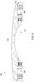
- FIG. 1 is a perspective view of an exemplary flow cell assembly 100.
- FIG. 2 is a cross-section of the exemplary flow cell assembly 100 of FIG. 1 .
- the exemplary flow cell assembly 100 includes a flow cell 110 having a flow cell bore 112 through which fluid can flow.
- the flow cell 110 has a plurality of sensor ports 114 in which a sensor port insert apparatus 300 ( FIG. 3 ) is installed.
- the sensor port 114 of the exemplary flow cell 110 is shaped so as to receive and place the exemplary sensor port insert apparatus 300 in physical contact with the fluid in the flow cell bore 112 of the flow cell 110.
- An ultrasonic signal transmitted from one sensor port insert apparatus 300 travels through the fluid within the flow cell bore 112 and is received by the other sensor port insert apparatus 300.
- the plurality of sensor port insert apparatuses 300 are connected to the flow meter 110 to determine the flow rate of the fluid.
- FIG. 3 is an exploded view of an exemplary sensor port insert apparatus 300.
- FIG. 4 is a cross-section of the exemplary sensor port insert apparatus 300 of FIG. 3 in one configuration.
- the sensor port insert apparatus 300 is designed to be installed into the sensor ports 114 of the exemplary flow cell 110 of FIG. 1 .
- the sensor port insert apparatus 300 includes an insert body 310 configured for insertion into the sensor port 114 of the flow cell 110 ( FIG. 1 ).
- the insert body 310 has an external surface that includes threads 319 or concentric grooves designed to dampen acoustic reflections/ring downs in the ultrasonic buffer 318 of the insert body 310.
- the threads 319 of the insert body 310 can be designed to be engaged with an interior threaded surface of a sensor port 114.
- One or more o-rings 311 can be installed on the exterior of the insert body 310 to provide a seal between the exterior of the insert body 310 and the sensor port 114.
- the insert body 310 defines a cavity 316 ( FIG. 4 ) having an opening 315 located at a first end 312 of the insert body 310.
- the second end 314 of the insert body includes an ultrasonic buffer 318.
- a transducer assembly 330 is located in the cavity 316 of the insert body 310 proximate to the ultrasonic buffer 318 for transmitting and receiving ultrasonic signals that travel through the fluid within the flow cell bore 112.
- the transducer assembly 330 includes a housing 340 having a second end 344 proximate to the ultrasonic buffer 318 and a first end 342 opposite of the second end 340.
- the first end 342 of the housing 340 is proximate to the opening 315 of the cavity 316.
- the transducer assembly 330 also includes a piezoelectric crystal 332 located in the second end 344 of the housing 340.
- the face 333 of the piezoelectric crystal 332 can be installed proximate to the interior surface 348 of the second end 344 of the housing 340.
- the exterior surface 346 or face of the second end 344 of the housing 340 is proximate to the ultrasonic buffer 318.
- the transducer assembly 330 can transmit and receive ultrasonic signals into and from the fluid to be measured through the ultrasonic buffer 318 of the insert body 310.
- the first end 342 of the housing 340 can include a back stem 338 for routing a wire 336 from the piezoceramic crystal 332 to a connector 339 (e.g., a BNC connector).
- a backing member 334 e.g., made from epoxy
- the wire 336 can extend from the piezoelectric crystal 332 through the backing member 334 to the back stem 338 of the transducer assembly 330.
- the transducer assembly 330 can be held in place by a transducer holding nut 350 located in the cavity 316 proximate to the first end 342 (e.g., the back stem 338) of the housing 340 applying a compressive force to the housing 340.
- the compressive force of the transducer holding nut 350 against the housing 340 keeps the second end 344 of the housing 340 proximate to the ultrasonic buffer 318.
- the transducer holding nut 350 can have an external surface that includes threads designed to be engaged with an interior threaded surface of the insert body 310.
- a disc spring 352 e.g., Bellville washer
- a washer 354 can be installed between the transducer holding nut 350 and the first end 342 of the housing 340.
- the disc spring 352 can provide additional compression against the housing 340 to keep the second end 344 of the housing 340 proximate to the ultrasonic buffer 318.
- a transducer holding nut o-ring 324 can be installed between the transducer holding nut 350 and the first end 342 of the housing 340 to keep external elements (e.g., moisture, air) from entering the cavity 316 of the insert body 310.
- An insert holding nut 372 can be threaded into the interior of the sensor port 114 to hold the insert body 310 in place.
- a plug 370 can be used to seal the sensor port 114.
- a coupling material 360 is located between the second end 344 of the housing 340 and the ultrasonic buffer 318.
- the coupling material 360 can provide a conductive medium for the ultrasonic signals between the exterior surface 346 of the second end 344 of the housing 340 and the ultrasonic buffer 318 by effectively coupling the piezoelectric crystal 333 to the ultrasonic buffer 318.
- the coupling material 360 is fluid form (e.g., liquid, gel, etc.), and can fill voids and displace air that could otherwise be located between the housing 340 and the ultrasonic buffer 318 that would interfere with the transmission quality of an ultrasonic signal passing through this location.
- the coupling material 360 is a composition including a room temperature vulcanizing (RTV) silicone material.
- RTV room temperature vulcanizing
- Other types of coupling materials 360 can be employed as long as the material does not cause any significant interference with the quality of ultrasonic signals passing through it.
- the coupling material 360 should not have high adhesive properties to avoid bonding between the transducer assembly 330 and the insert body 310 to allow replacement of the transducer assembly 330.
- the coupling material 360 remains a fluid, it may be susceptible to leakage from the area between the second end 344 of the housing 340 and the ultrasonic buffer 318.
- the transducer holding nut o-ring 324 can be installed between the transducer holding nut 350 and the first end 342 of the housing 340 to keep external elements (e.g., moisture, air) from entering the cavity 316 of the insert body 310 and potentially causing evaporation of the coupling material 360. As shown in FIG.
- a face o-ring 320 can be located within the cavity 316 of the insert body 310 proximate to the second end 344 of the housing 340 to assist in preventing the leakage of the coupling material 360 from the area between the second end of the housing 344 and the ultrasonic buffer 318.
- the face o-ring 320 wraps around the perimeter of the exterior surface 346 of the second end 344 of the housing 340.
- the face o-ring 320 is located in a groove in the exterior surface 346 of the second end 344 of the housing 340 to accommodate engagement between the face o-ring 320 and the housing 340.
- the face o-ring 320 is located in a groove in the insert body 310 on the ultrasonic buffer 316.
- FIG. 5 is a cross-section of another exemplary sensor port insert apparatus 400.
- a groove 317 in the cavity 316 of the insert body 310 proximate to the exterior surface 346 of the second end 344 of the housing 340 is provided.
- a insert groove o-ring 322 is installed in the groove 317 to assist in preventing the leakage of the coupling material 360 from the area between the second end of the housing 344 and the ultrasonic buffer 318.
- the insert groove o-ring 322 and associated groove 317 can be located closer to the transducer holding nut 350 (e.g., anywhere proximate to the transducer housing 340) to enable more coupling material to be stored within the cavity 316 of the transducer assembly 300 while surrounding the exterior surface 346 of the second end 344 of the housing 340.
- the insert groove o-ring 322 could be located between the holding nut 350 and the first end 342 of the housing 340 (e.g., between the holding nut 350 and the back stem 338) to provide the required sealing.
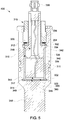
- FIG. 6 is a cross-section of yet another exemplary sensor port insert apparatus 500.
- the sensor port insert apparatus 500 of FIG. 6 does not use coupling material 360, eliminating the need for a face o-ring 320 or an insert groove o-ring 322.
- the face 333 of the piezoelectric crystal 332 can be installed proximate to the interior surface 348 of the second end 344 of the housing 340.
- transducer assembly 330 can be held in place by a transducer holding nut 350 applying a compressive force to the housing 340 to keep the exterior surface 346 of the second end 344 of the housing 340 in contact the ultrasonic buffer 318.
- the disc spring 352 can provide additional compression against the housing 340 to keep the exterior surface 346 of the housing 340 in contact with the ultrasonic buffer 318.
- the exterior surface 346 of the second end 344 of the housing 340 in contact with the interior surface 313 of the ultrasonic buffer 318 is polished, and the interior surface 313 of the ultrasonic buffer 318 in the cavity 316 is polished.
- the polishing eliminates voids and displaces air that could otherwise be located between the exterior surface 346 of the second end 344 of the housing 340 and the interior surface 313 of the ultrasonic buffer 318 when the exterior surface 346 of the second end 344 of the housing 340 contacts the interior surface 313 of the buffer 318.
Landscapes
- Physics & Mathematics (AREA)
- Fluid Mechanics (AREA)
- General Physics & Mathematics (AREA)
- Electromagnetism (AREA)
- Measuring Volume Flow (AREA)
- Optical Measuring Cells (AREA)
- Investigating Or Analyzing Materials By The Use Of Ultrasonic Waves (AREA)
Applications Claiming Priority (2)
| Application Number | Priority Date | Filing Date | Title |
|---|---|---|---|
| US13/408,025 US8844347B2 (en) | 2012-02-29 | 2012-02-29 | Sensor port insert apparatus |
| PCT/US2013/027207 WO2013130343A2 (en) | 2012-02-29 | 2013-02-22 | Sensor port insert apparatus |
Publications (2)
| Publication Number | Publication Date |
|---|---|
| EP2820386A2 EP2820386A2 (en) | 2015-01-07 |
| EP2820386B1 true EP2820386B1 (en) | 2020-04-01 |
Family
ID=47833413
Family Applications (1)
| Application Number | Title | Priority Date | Filing Date |
|---|---|---|---|
| EP13708015.6A Active EP2820386B1 (en) | 2012-02-29 | 2013-02-22 | Sensor port insert apparatus |
Country Status (5)
| Country | Link |
|---|---|
| US (1) | US8844347B2 (ja) |
| EP (1) | EP2820386B1 (ja) |
| JP (1) | JP6082760B2 (ja) |
| CN (1) | CN104364613B (ja) |
| WO (1) | WO2013130343A2 (ja) |
Families Citing this family (12)
| Publication number | Priority date | Publication date | Assignee | Title |
|---|---|---|---|---|
| US9140586B2 (en) | 2012-09-25 | 2015-09-22 | General Electric Company | Removable sensor port insert apparatus |
| US9151651B2 (en) * | 2013-01-14 | 2015-10-06 | General Electric Company | Apparatus and method for determining temperature |
| EP2759809B1 (de) * | 2013-01-28 | 2020-02-12 | Krohne AG | Ultraschallwandler |
| DE102013020497B4 (de) * | 2013-01-28 | 2018-10-11 | Krohne Ag | Baueinheit aus einem Ultraschallwandler und einen Wandlerhalter |
| US9259827B2 (en) | 2013-10-11 | 2016-02-16 | General Electric Company | Apparatus for holding and applying torque to a nut |
| CN103612113B (zh) * | 2013-10-29 | 2016-03-02 | 杭州电子科技大学 | 压电换能器螺母与套筒扳手对准装置 |
| CN206440316U (zh) * | 2017-01-23 | 2017-08-25 | 青岛海威茨仪表有限公司 | 一种多通道超声波流量计 |
| GB201713895D0 (en) * | 2017-08-30 | 2017-10-11 | Sentec Ltd | Transducer drive and damping technique |
| US11590535B2 (en) * | 2017-10-25 | 2023-02-28 | Honeywell International Inc. | Ultrasonic transducer |
| MX2020007984A (es) * | 2018-02-01 | 2020-10-16 | Reliance Worldwide Corp | Montaje de sensor. |
| WO2019152040A1 (en) | 2018-02-01 | 2019-08-08 | Reliance Worldwide Corporation | Flow tube for hosting a flow meter and a shut-off valve |
| WO2020014452A1 (en) * | 2018-07-12 | 2020-01-16 | Abilene Christian University | Apparatus, systems, and methods for non-invasive measurement of flow in a high temperature pipe |
Citations (6)
| Publication number | Priority date | Publication date | Assignee | Title |
|---|---|---|---|---|
| US3935484A (en) * | 1974-02-25 | 1976-01-27 | Westinghouse Electric Corporation | Replaceable acoustic transducer assembly |
| US4783997A (en) * | 1987-02-26 | 1988-11-15 | Panametrics, Inc. | Ultrasonic transducers for high temperature applications |
| US5379658A (en) * | 1992-11-16 | 1995-01-10 | Simmonds Precision Products, Inc. | Intrusive acoustic sensor mounting arrangement |
| US6343511B1 (en) * | 1995-06-07 | 2002-02-05 | Panametrics, Inc. | Ultrasonic path bundle and systems |
| EP1345206A2 (en) * | 2002-03-12 | 2003-09-17 | Caldon, Inc. | A method for obtaining information about fluid in a pipe, and an element for placement in a pipe having means for holding an acoustic transducer |
| US20070035211A1 (en) * | 2005-08-12 | 2007-02-15 | Daniel Measurement And Control, Inc. | Transducer housing for an ultrasonic fluid meter |
Family Cites Families (20)
| Publication number | Priority date | Publication date | Assignee | Title |
|---|---|---|---|---|
| US3732728A (en) * | 1971-01-04 | 1973-05-15 | Fitzpatrick D | Bottom hole pressure and temperature indicator |
| US3771117A (en) * | 1972-03-01 | 1973-11-06 | Westinghouse Electric Corp | Transducer installation |
| JPS58173431A (ja) * | 1982-04-06 | 1983-10-12 | Mitsubishi Electric Corp | 超音波流量計 |
| JPH0537218Y2 (ja) * | 1986-02-13 | 1993-09-21 | ||
| US4742717A (en) * | 1986-09-16 | 1988-05-10 | Kaijo Denki Co., Ltd. | Gas flow rate measuring device |
| US5853020A (en) * | 1995-06-23 | 1998-12-29 | Widner; Ronald D. | Miniature combination valve and pressure transducer and system |
| US6280388B1 (en) | 1997-11-19 | 2001-08-28 | Boston Scientific Technology, Inc. | Aerogel backed ultrasound transducer |
| WO2001045550A2 (en) | 1999-12-23 | 2001-06-28 | Therus Corporation | Ultrasound transducers for imaging and therapy |
| US6467138B1 (en) | 2000-05-24 | 2002-10-22 | Vermon | Integrated connector backings for matrix array transducers, matrix array transducers employing such backings and methods of making the same |
| US6589180B2 (en) | 2001-06-20 | 2003-07-08 | Bae Systems Information And Electronic Systems Integration, Inc | Acoustical array with multilayer substrate integrated circuits |
| JP4707088B2 (ja) * | 2004-04-27 | 2011-06-22 | 愛知時計電機株式会社 | 超音波流量計 |
| US7398160B2 (en) * | 2004-06-30 | 2008-07-08 | Southwest Research Institute | Gas energy meter for inferential determination of thermophysical properties of a gas mixture at multiple states of the gas |
| US7913806B2 (en) | 2005-05-10 | 2011-03-29 | Schlumberger Technology Corporation | Enclosures for containing transducers and electronics on a downhole tool |
| CN100587988C (zh) * | 2005-08-12 | 2010-02-03 | 丹尼尔度量和控制公司 | 用于超声流量计的换能器组件 |
| US7464600B2 (en) * | 2006-08-25 | 2008-12-16 | Kulite Semiconductor Products, Inc. | Combined temperature and pressure transducer incorporating connector keyway alignment and an alignment method |
| US7628081B1 (en) * | 2007-03-05 | 2009-12-08 | Murray F Feller | Acoustic pulse flow meter |
| US7966893B2 (en) * | 2009-06-16 | 2011-06-28 | Daniel Measurement And Control, Inc. | Adjusting transducer frequency without ceasing fluid flow through a meter |
| US8100019B2 (en) * | 2010-04-07 | 2012-01-24 | Mkt Engineering, Llc | Cartridge fluid transducer |
| US20110247431A1 (en) * | 2010-04-07 | 2011-10-13 | Daniel Ervin Moldenhauer | Cartridge Flow Transducer |
| US8684093B2 (en) * | 2010-04-23 | 2014-04-01 | Bench Tree Group, Llc | Electromechanical actuator apparatus and method for down-hole tools |
-
2012
- 2012-02-29 US US13/408,025 patent/US8844347B2/en active Active
-
2013
- 2013-02-22 WO PCT/US2013/027207 patent/WO2013130343A2/en active Application Filing
- 2013-02-22 CN CN201380011697.6A patent/CN104364613B/zh active Active
- 2013-02-22 EP EP13708015.6A patent/EP2820386B1/en active Active
- 2013-02-22 JP JP2014559929A patent/JP6082760B2/ja active Active
Patent Citations (6)
| Publication number | Priority date | Publication date | Assignee | Title |
|---|---|---|---|---|
| US3935484A (en) * | 1974-02-25 | 1976-01-27 | Westinghouse Electric Corporation | Replaceable acoustic transducer assembly |
| US4783997A (en) * | 1987-02-26 | 1988-11-15 | Panametrics, Inc. | Ultrasonic transducers for high temperature applications |
| US5379658A (en) * | 1992-11-16 | 1995-01-10 | Simmonds Precision Products, Inc. | Intrusive acoustic sensor mounting arrangement |
| US6343511B1 (en) * | 1995-06-07 | 2002-02-05 | Panametrics, Inc. | Ultrasonic path bundle and systems |
| EP1345206A2 (en) * | 2002-03-12 | 2003-09-17 | Caldon, Inc. | A method for obtaining information about fluid in a pipe, and an element for placement in a pipe having means for holding an acoustic transducer |
| US20070035211A1 (en) * | 2005-08-12 | 2007-02-15 | Daniel Measurement And Control, Inc. | Transducer housing for an ultrasonic fluid meter |
Also Published As
| Publication number | Publication date |
|---|---|
| CN104364613B (zh) | 2019-03-08 |
| US20130219707A1 (en) | 2013-08-29 |
| JP6082760B2 (ja) | 2017-02-15 |
| CN104364613A (zh) | 2015-02-18 |
| WO2013130343A2 (en) | 2013-09-06 |
| WO2013130343A3 (en) | 2013-10-31 |
| EP2820386A2 (en) | 2015-01-07 |
| JP2015508904A (ja) | 2015-03-23 |
| US8844347B2 (en) | 2014-09-30 |
Similar Documents
| Publication | Publication Date | Title |
|---|---|---|
| EP2820386B1 (en) | Sensor port insert apparatus | |
| US8356523B2 (en) | Ultrasonic sensor of a measuring system for determining and/or monitoring flow of a measured medium through a measuring tube | |
| JP4702668B2 (ja) | 流量測定装置 | |
| EP1850097B1 (en) | Transducer assembly | |
| KR101531648B1 (ko) | 초음파 유량계 | |
| JP6411807B2 (ja) | トランスデューサシステム | |
| US8534138B2 (en) | Chordal gas flowmeter with transducers installed outside the pressure boundary, housing and method | |
| US8899116B2 (en) | Replaceable ultrasonic transducer for an ultrasonic flow measuring device | |
| US20110174083A1 (en) | Method and measuring system for determining and/or monitoring the flow of a measured medium through a measuring tube | |
| JP2010523972A5 (ja) | ||
| WO2008123906A4 (en) | Flangeless differential pressure transmitter for industrial process control systems | |
| US20130192386A1 (en) | Ultrasonic transducer for a flow measuring device | |
| EP2545345B1 (en) | Apparatus and method for sensing fluid flow in a pipe with variable wall thickness | |
| CN104457869A (zh) | 超声波流量计 | |
| US8547000B2 (en) | Ultrasonic, flow measuring device | |
| JP6503462B2 (ja) | ロッド式圧力伝達継手及び継手装置 | |
| EP3245487B1 (en) | Transit time flow meter apparatus, transducer, flow meter and method | |
| US20220412828A1 (en) | Transducer assembly with header with improved configuration including side pins | |
| JP5580950B1 (ja) | 超音波流量計 | |
| EP2141463B1 (en) | Ultrasound flow meter with transducer cartridge mounting surface and sealing means | |
| US20080060449A1 (en) | Pressure drop flow meter having interchangeable, metal-to-metal sealing metering element | |
| JP2019027925A (ja) | 熱式流量計 |
Legal Events
| Date | Code | Title | Description |
|---|---|---|---|
| PUAI | Public reference made under article 153(3) epc to a published international application that has entered the european phase |
Free format text: ORIGINAL CODE: 0009012 |
|
| 17P | Request for examination filed |
Effective date: 20140929 |
|
| AK | Designated contracting states |
Kind code of ref document: A2 Designated state(s): AL AT BE BG CH CY CZ DE DK EE ES FI FR GB GR HR HU IE IS IT LI LT LU LV MC MK MT NL NO PL PT RO RS SE SI SK SM TR |
|
| AX | Request for extension of the european patent |
Extension state: BA ME |
|
| DAX | Request for extension of the european patent (deleted) | ||
| PUAG | Search results despatched under rule 164(2) epc together with communication from examining division |
Free format text: ORIGINAL CODE: 0009017 |
|
| STAA | Information on the status of an ep patent application or granted ep patent |
Free format text: STATUS: EXAMINATION IS IN PROGRESS |
|
| 17Q | First examination report despatched |
Effective date: 20161214 |
|
| B565 | Issuance of search results under rule 164(2) epc |
Effective date: 20161214 |
|
| RIC1 | Information provided on ipc code assigned before grant |
Ipc: G01F 15/14 20060101ALI20171106BHEP Ipc: G01F 1/66 20060101AFI20171106BHEP |
|
| GRAP | Despatch of communication of intention to grant a patent |
Free format text: ORIGINAL CODE: EPIDOSNIGR1 |
|
| STAA | Information on the status of an ep patent application or granted ep patent |
Free format text: STATUS: GRANT OF PATENT IS INTENDED |
|
| INTG | Intention to grant announced |
Effective date: 20190401 |
|
| GRAS | Grant fee paid |
Free format text: ORIGINAL CODE: EPIDOSNIGR3 |
|
| GRAA | (expected) grant |
Free format text: ORIGINAL CODE: 0009210 |
|
| STAA | Information on the status of an ep patent application or granted ep patent |
Free format text: STATUS: THE PATENT HAS BEEN GRANTED |
|
| AK | Designated contracting states |
Kind code of ref document: B1 Designated state(s): AL AT BE BG CH CY CZ DE DK EE ES FI FR GB GR HR HU IE IS IT LI LT LU LV MC MK MT NL NO PL PT RO RS SE SI SK SM TR |
|
| REG | Reference to a national code |
Ref country code: GB Ref legal event code: FG4D |
|
| REG | Reference to a national code |
Ref country code: AT Ref legal event code: REF Ref document number: 1251949 Country of ref document: AT Kind code of ref document: T Effective date: 20200415 Ref country code: CH Ref legal event code: EP |
|
| REG | Reference to a national code |
Ref country code: DE Ref legal event code: R096 Ref document number: 602013067407 Country of ref document: DE |
|
| REG | Reference to a national code |
Ref country code: IE Ref legal event code: FG4D |
|
| REG | Reference to a national code |
Ref country code: NL Ref legal event code: FP |
|
| PG25 | Lapsed in a contracting state [announced via postgrant information from national office to epo] |
Ref country code: BG Free format text: LAPSE BECAUSE OF FAILURE TO SUBMIT A TRANSLATION OF THE DESCRIPTION OR TO PAY THE FEE WITHIN THE PRESCRIBED TIME-LIMIT Effective date: 20200701 |
|
| REG | Reference to a national code |
Ref country code: LT Ref legal event code: MG4D |
|
| PG25 | Lapsed in a contracting state [announced via postgrant information from national office to epo] |
Ref country code: SE Free format text: LAPSE BECAUSE OF FAILURE TO SUBMIT A TRANSLATION OF THE DESCRIPTION OR TO PAY THE FEE WITHIN THE PRESCRIBED TIME-LIMIT Effective date: 20200401 Ref country code: PT Free format text: LAPSE BECAUSE OF FAILURE TO SUBMIT A TRANSLATION OF THE DESCRIPTION OR TO PAY THE FEE WITHIN THE PRESCRIBED TIME-LIMIT Effective date: 20200817 Ref country code: CZ Free format text: LAPSE BECAUSE OF FAILURE TO SUBMIT A TRANSLATION OF THE DESCRIPTION OR TO PAY THE FEE WITHIN THE PRESCRIBED TIME-LIMIT Effective date: 20200401 Ref country code: LT Free format text: LAPSE BECAUSE OF FAILURE TO SUBMIT A TRANSLATION OF THE DESCRIPTION OR TO PAY THE FEE WITHIN THE PRESCRIBED TIME-LIMIT Effective date: 20200401 Ref country code: IS Free format text: LAPSE BECAUSE OF FAILURE TO SUBMIT A TRANSLATION OF THE DESCRIPTION OR TO PAY THE FEE WITHIN THE PRESCRIBED TIME-LIMIT Effective date: 20200801 Ref country code: NO Free format text: LAPSE BECAUSE OF FAILURE TO SUBMIT A TRANSLATION OF THE DESCRIPTION OR TO PAY THE FEE WITHIN THE PRESCRIBED TIME-LIMIT Effective date: 20200701 Ref country code: FI Free format text: LAPSE BECAUSE OF FAILURE TO SUBMIT A TRANSLATION OF THE DESCRIPTION OR TO PAY THE FEE WITHIN THE PRESCRIBED TIME-LIMIT Effective date: 20200401 Ref country code: GR Free format text: LAPSE BECAUSE OF FAILURE TO SUBMIT A TRANSLATION OF THE DESCRIPTION OR TO PAY THE FEE WITHIN THE PRESCRIBED TIME-LIMIT Effective date: 20200702 |
|
| REG | Reference to a national code |
Ref country code: AT Ref legal event code: MK05 Ref document number: 1251949 Country of ref document: AT Kind code of ref document: T Effective date: 20200401 |
|
| PG25 | Lapsed in a contracting state [announced via postgrant information from national office to epo] |
Ref country code: RS Free format text: LAPSE BECAUSE OF FAILURE TO SUBMIT A TRANSLATION OF THE DESCRIPTION OR TO PAY THE FEE WITHIN THE PRESCRIBED TIME-LIMIT Effective date: 20200401 Ref country code: LV Free format text: LAPSE BECAUSE OF FAILURE TO SUBMIT A TRANSLATION OF THE DESCRIPTION OR TO PAY THE FEE WITHIN THE PRESCRIBED TIME-LIMIT Effective date: 20200401 Ref country code: HR Free format text: LAPSE BECAUSE OF FAILURE TO SUBMIT A TRANSLATION OF THE DESCRIPTION OR TO PAY THE FEE WITHIN THE PRESCRIBED TIME-LIMIT Effective date: 20200401 |
|
| PG25 | Lapsed in a contracting state [announced via postgrant information from national office to epo] |
Ref country code: AL Free format text: LAPSE BECAUSE OF FAILURE TO SUBMIT A TRANSLATION OF THE DESCRIPTION OR TO PAY THE FEE WITHIN THE PRESCRIBED TIME-LIMIT Effective date: 20200401 |
|
| REG | Reference to a national code |
Ref country code: DE Ref legal event code: R097 Ref document number: 602013067407 Country of ref document: DE |
|
| PG25 | Lapsed in a contracting state [announced via postgrant information from national office to epo] |
Ref country code: IT Free format text: LAPSE BECAUSE OF FAILURE TO SUBMIT A TRANSLATION OF THE DESCRIPTION OR TO PAY THE FEE WITHIN THE PRESCRIBED TIME-LIMIT Effective date: 20200401 Ref country code: SM Free format text: LAPSE BECAUSE OF FAILURE TO SUBMIT A TRANSLATION OF THE DESCRIPTION OR TO PAY THE FEE WITHIN THE PRESCRIBED TIME-LIMIT Effective date: 20200401 Ref country code: EE Free format text: LAPSE BECAUSE OF FAILURE TO SUBMIT A TRANSLATION OF THE DESCRIPTION OR TO PAY THE FEE WITHIN THE PRESCRIBED TIME-LIMIT Effective date: 20200401 Ref country code: AT Free format text: LAPSE BECAUSE OF FAILURE TO SUBMIT A TRANSLATION OF THE DESCRIPTION OR TO PAY THE FEE WITHIN THE PRESCRIBED TIME-LIMIT Effective date: 20200401 Ref country code: DK Free format text: LAPSE BECAUSE OF FAILURE TO SUBMIT A TRANSLATION OF THE DESCRIPTION OR TO PAY THE FEE WITHIN THE PRESCRIBED TIME-LIMIT Effective date: 20200401 Ref country code: RO Free format text: LAPSE BECAUSE OF FAILURE TO SUBMIT A TRANSLATION OF THE DESCRIPTION OR TO PAY THE FEE WITHIN THE PRESCRIBED TIME-LIMIT Effective date: 20200401 Ref country code: ES Free format text: LAPSE BECAUSE OF FAILURE TO SUBMIT A TRANSLATION OF THE DESCRIPTION OR TO PAY THE FEE WITHIN THE PRESCRIBED TIME-LIMIT Effective date: 20200401 |
|
| PLBE | No opposition filed within time limit |
Free format text: ORIGINAL CODE: 0009261 |
|
| STAA | Information on the status of an ep patent application or granted ep patent |
Free format text: STATUS: NO OPPOSITION FILED WITHIN TIME LIMIT |
|
| PG25 | Lapsed in a contracting state [announced via postgrant information from national office to epo] |
Ref country code: SK Free format text: LAPSE BECAUSE OF FAILURE TO SUBMIT A TRANSLATION OF THE DESCRIPTION OR TO PAY THE FEE WITHIN THE PRESCRIBED TIME-LIMIT Effective date: 20200401 Ref country code: PL Free format text: LAPSE BECAUSE OF FAILURE TO SUBMIT A TRANSLATION OF THE DESCRIPTION OR TO PAY THE FEE WITHIN THE PRESCRIBED TIME-LIMIT Effective date: 20200401 |
|
| 26N | No opposition filed |
Effective date: 20210112 |
|
| PG25 | Lapsed in a contracting state [announced via postgrant information from national office to epo] |
Ref country code: SI Free format text: LAPSE BECAUSE OF FAILURE TO SUBMIT A TRANSLATION OF THE DESCRIPTION OR TO PAY THE FEE WITHIN THE PRESCRIBED TIME-LIMIT Effective date: 20200401 |
|
| PG25 | Lapsed in a contracting state [announced via postgrant information from national office to epo] |
Ref country code: MC Free format text: LAPSE BECAUSE OF FAILURE TO SUBMIT A TRANSLATION OF THE DESCRIPTION OR TO PAY THE FEE WITHIN THE PRESCRIBED TIME-LIMIT Effective date: 20200401 |
|
| REG | Reference to a national code |
Ref country code: BE Ref legal event code: MM Effective date: 20210228 |
|
| PG25 | Lapsed in a contracting state [announced via postgrant information from national office to epo] |
Ref country code: LU Free format text: LAPSE BECAUSE OF NON-PAYMENT OF DUE FEES Effective date: 20210222 |
|
| PG25 | Lapsed in a contracting state [announced via postgrant information from national office to epo] |
Ref country code: FR Free format text: LAPSE BECAUSE OF NON-PAYMENT OF DUE FEES Effective date: 20210228 Ref country code: IE Free format text: LAPSE BECAUSE OF NON-PAYMENT OF DUE FEES Effective date: 20210222 |
|
| PG25 | Lapsed in a contracting state [announced via postgrant information from national office to epo] |
Ref country code: BE Free format text: LAPSE BECAUSE OF NON-PAYMENT OF DUE FEES Effective date: 20210228 |
|
| PG25 | Lapsed in a contracting state [announced via postgrant information from national office to epo] |
Ref country code: HU Free format text: LAPSE BECAUSE OF FAILURE TO SUBMIT A TRANSLATION OF THE DESCRIPTION OR TO PAY THE FEE WITHIN THE PRESCRIBED TIME-LIMIT; INVALID AB INITIO Effective date: 20130222 |
|
| PG25 | Lapsed in a contracting state [announced via postgrant information from national office to epo] |
Ref country code: CY Free format text: LAPSE BECAUSE OF FAILURE TO SUBMIT A TRANSLATION OF THE DESCRIPTION OR TO PAY THE FEE WITHIN THE PRESCRIBED TIME-LIMIT Effective date: 20200401 |
|
| P01 | Opt-out of the competence of the unified patent court (upc) registered |
Effective date: 20230526 |
|
| PGFP | Annual fee paid to national office [announced via postgrant information from national office to epo] |
Ref country code: NL Payment date: 20240123 Year of fee payment: 12 |
|
| PG25 | Lapsed in a contracting state [announced via postgrant information from national office to epo] |
Ref country code: MK Free format text: LAPSE BECAUSE OF FAILURE TO SUBMIT A TRANSLATION OF THE DESCRIPTION OR TO PAY THE FEE WITHIN THE PRESCRIBED TIME-LIMIT Effective date: 20200401 |
|
| PGFP | Annual fee paid to national office [announced via postgrant information from national office to epo] |
Ref country code: DE Payment date: 20240123 Year of fee payment: 12 Ref country code: GB Payment date: 20240123 Year of fee payment: 12 Ref country code: CH Payment date: 20240301 Year of fee payment: 12 |