EP2820384B1 - Method for contactlessly measuring a relative position by means of a 3d hall sensor having measurement signal store - Google Patents
Method for contactlessly measuring a relative position by means of a 3d hall sensor having measurement signal store Download PDFInfo
- Publication number
- EP2820384B1 EP2820384B1 EP13709809.1A EP13709809A EP2820384B1 EP 2820384 B1 EP2820384 B1 EP 2820384B1 EP 13709809 A EP13709809 A EP 13709809A EP 2820384 B1 EP2820384 B1 EP 2820384B1
- Authority
- EP
- European Patent Office
- Prior art keywords
- magnetic field
- sensor
- flux density
- magnitude
- position signal
- Prior art date
- Legal status (The legal status is an assumption and is not a legal conclusion. Google has not performed a legal analysis and makes no representation as to the accuracy of the status listed.)
- Active
Links
- 238000000034 method Methods 0.000 title claims description 17
- 238000005259 measurement Methods 0.000 title description 52
- 238000006073 displacement reaction Methods 0.000 claims description 42
- 230000004907 flux Effects 0.000 claims description 27
- 238000001514 detection method Methods 0.000 description 9
- 238000000691 measurement method Methods 0.000 description 5
- 230000007935 neutral effect Effects 0.000 description 3
- 230000005355 Hall effect Effects 0.000 description 2
- 230000003287 optical effect Effects 0.000 description 2
- 230000001419 dependent effect Effects 0.000 description 1
- 238000011161 development Methods 0.000 description 1
- 230000018109 developmental process Effects 0.000 description 1
- 238000011156 evaluation Methods 0.000 description 1
- 230000001939 inductive effect Effects 0.000 description 1
- 230000003993 interaction Effects 0.000 description 1
- 230000010355 oscillation Effects 0.000 description 1
- 238000012545 processing Methods 0.000 description 1
Images


Classifications
-
- G—PHYSICS
- G01—MEASURING; TESTING
- G01B—MEASURING LENGTH, THICKNESS OR SIMILAR LINEAR DIMENSIONS; MEASURING ANGLES; MEASURING AREAS; MEASURING IRREGULARITIES OF SURFACES OR CONTOURS
- G01B7/00—Measuring arrangements characterised by the use of electric or magnetic techniques
- G01B7/30—Measuring arrangements characterised by the use of electric or magnetic techniques for measuring angles or tapers; for testing the alignment of axes
-
- G—PHYSICS
- G01—MEASURING; TESTING
- G01D—MEASURING NOT SPECIALLY ADAPTED FOR A SPECIFIC VARIABLE; ARRANGEMENTS FOR MEASURING TWO OR MORE VARIABLES NOT COVERED IN A SINGLE OTHER SUBCLASS; TARIFF METERING APPARATUS; MEASURING OR TESTING NOT OTHERWISE PROVIDED FOR
- G01D5/00—Mechanical means for transferring the output of a sensing member; Means for converting the output of a sensing member to another variable where the form or nature of the sensing member does not constrain the means for converting; Transducers not specially adapted for a specific variable
- G01D5/12—Mechanical means for transferring the output of a sensing member; Means for converting the output of a sensing member to another variable where the form or nature of the sensing member does not constrain the means for converting; Transducers not specially adapted for a specific variable using electric or magnetic means
- G01D5/244—Mechanical means for transferring the output of a sensing member; Means for converting the output of a sensing member to another variable where the form or nature of the sensing member does not constrain the means for converting; Transducers not specially adapted for a specific variable using electric or magnetic means influencing characteristics of pulses or pulse trains; generating pulses or pulse trains
- G01D5/24471—Error correction
- G01D5/24495—Error correction using previous values
-
- G—PHYSICS
- G01—MEASURING; TESTING
- G01B—MEASURING LENGTH, THICKNESS OR SIMILAR LINEAR DIMENSIONS; MEASURING ANGLES; MEASURING AREAS; MEASURING IRREGULARITIES OF SURFACES OR CONTOURS
- G01B7/00—Measuring arrangements characterised by the use of electric or magnetic techniques
- G01B7/004—Measuring arrangements characterised by the use of electric or magnetic techniques for measuring coordinates of points
-
- G—PHYSICS
- G01—MEASURING; TESTING
- G01D—MEASURING NOT SPECIALLY ADAPTED FOR A SPECIFIC VARIABLE; ARRANGEMENTS FOR MEASURING TWO OR MORE VARIABLES NOT COVERED IN A SINGLE OTHER SUBCLASS; TARIFF METERING APPARATUS; MEASURING OR TESTING NOT OTHERWISE PROVIDED FOR
- G01D5/00—Mechanical means for transferring the output of a sensing member; Means for converting the output of a sensing member to another variable where the form or nature of the sensing member does not constrain the means for converting; Transducers not specially adapted for a specific variable
- G01D5/12—Mechanical means for transferring the output of a sensing member; Means for converting the output of a sensing member to another variable where the form or nature of the sensing member does not constrain the means for converting; Transducers not specially adapted for a specific variable using electric or magnetic means
- G01D5/14—Mechanical means for transferring the output of a sensing member; Means for converting the output of a sensing member to another variable where the form or nature of the sensing member does not constrain the means for converting; Transducers not specially adapted for a specific variable using electric or magnetic means influencing the magnitude of a current or voltage
- G01D5/142—Mechanical means for transferring the output of a sensing member; Means for converting the output of a sensing member to another variable where the form or nature of the sensing member does not constrain the means for converting; Transducers not specially adapted for a specific variable using electric or magnetic means influencing the magnitude of a current or voltage using Hall-effect devices
- G01D5/145—Mechanical means for transferring the output of a sensing member; Means for converting the output of a sensing member to another variable where the form or nature of the sensing member does not constrain the means for converting; Transducers not specially adapted for a specific variable using electric or magnetic means influencing the magnitude of a current or voltage using Hall-effect devices influenced by the relative movement between the Hall device and magnetic fields
-
- G—PHYSICS
- G01—MEASURING; TESTING
- G01D—MEASURING NOT SPECIALLY ADAPTED FOR A SPECIFIC VARIABLE; ARRANGEMENTS FOR MEASURING TWO OR MORE VARIABLES NOT COVERED IN A SINGLE OTHER SUBCLASS; TARIFF METERING APPARATUS; MEASURING OR TESTING NOT OTHERWISE PROVIDED FOR
- G01D5/00—Mechanical means for transferring the output of a sensing member; Means for converting the output of a sensing member to another variable where the form or nature of the sensing member does not constrain the means for converting; Transducers not specially adapted for a specific variable
- G01D5/12—Mechanical means for transferring the output of a sensing member; Means for converting the output of a sensing member to another variable where the form or nature of the sensing member does not constrain the means for converting; Transducers not specially adapted for a specific variable using electric or magnetic means
- G01D5/14—Mechanical means for transferring the output of a sensing member; Means for converting the output of a sensing member to another variable where the form or nature of the sensing member does not constrain the means for converting; Transducers not specially adapted for a specific variable using electric or magnetic means influencing the magnitude of a current or voltage
- G01D5/142—Mechanical means for transferring the output of a sensing member; Means for converting the output of a sensing member to another variable where the form or nature of the sensing member does not constrain the means for converting; Transducers not specially adapted for a specific variable using electric or magnetic means influencing the magnitude of a current or voltage using Hall-effect devices
Definitions
- the present invention relates to a method for contactlessly measuring a relative position of a magnetic field source which produces a magnetic field and a magnetic field sensor in relation to each other.
- the present invention further also relates to a corresponding displacement sensor.
- the invention describes an operating principle of a sensor which is based on the Hall effect and which achieves an increase in the sensor output range with a magnet which is simultaneously reduced in size by storing the earlier value when control by the magnetic field is lost.
- linear movements are intended to be detected and evaluated contactlessly by means of magnetic interaction between one or more permanent magnets and a magnetic sensor based on the Hall effect.
- the measurement of linear movements is used, for example, for controlling machine tools, in pneumatics, in automation technology and robotics and in the automotive sector.
- a contactless detection of movements affords the advantage inter alia of freedom from wear.
- the optical and magnetic methods are the most widespread among the contactless measurement methods. Whilst the optical methods ensure a very high level of precision owing to the small wavelength of light, magnetic methods are far less sensitive to dirt and damage, in particular in that magnets and sensor components can be completely enclosed in a non-magnetic hermetic casing.
- this principle has the advantage that it is comparatively not very sensitive to a change in the absolute magnetic field strength because proportional numbers between the field components are used to detect the position.
- European Patent specification EP 0979988 B1 discloses measurement methods for contactless magnetic detection of relative linear movements between permanent magnets and electronic sensors. In order to detect the relative linear movements by means of the electronic sensors, there are detected at a position two mutually perpendicular field components whose quotient is evaluated in order to detect the position.
- the known measurement method can also be carried out in such a manner that, in order to detect the relative linear movements by means of the electronic sensors, there are detected at two locations two mutually perpendicular field components whose quotient is evaluated in order to detect the position.
- the published European Patent Application EP2159546 A2 discloses a measurement method for the contactless detection of relative linear movements between a sensor arrangement for detecting two mutually perpendicular magnetic field components (R, A) and a permanent magnet.
- a two or three-dimensional Hall sensor is used in place of individual sensors for detecting various field components.
- the published European Patent Application EP1243897 A1 relates to a magnetic displacement sensor which comprises a magnetic field source and a magnetic field sensor which can be displaced relative to each other along a predetermined path.
- the magnetic field sensor measures two components of the magnetic field produced by the magnetic field source. There is then derived from the measured components a position signal which constitutes the relative position of the magnetic field sensor and magnetic field source.
- the explanations set out in this publication in respect of the displacement sensor are distinguished in that the establishment of the position signal contains a division of the two measured components of the magnetic field.
- Figure 1 shows an arrangement in which a Hall sensor 100 is arranged in a fixed position in order to contactlessly detect a linear movement and the magnetic field of a movable permanent magnet 102 is detected.
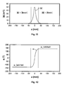
- the magnetic field extending in the direction of movement is subsequently designated to be the magnetic field component Bz and the component extending transversely thereto is subsequently designated By.
- Figure 2 shows the path of the components By and Bz of the magnetic flux density in accordance with the location z at which the permanent magnet 102 is located.
- the zero position is the position at which the permanent magnet 102 and the sensor 100 are directly opposite each other.
- the angle ⁇ which can be calculated in accordance with the following equation (1) is generally used as the measurement signal.
- ⁇ arctan B z B y
- the angle ⁇ depends comparatively linearly on the position of the permanent magnet 102 up to a given limit value in relation to the Hall sensor 100.
- the currently measured characteristic line is generally further linearised, as illustrated in Figure 4 by means of the line ⁇ _lin. That linearised line ⁇ _lin then forms the output characteristic line of the sensor.
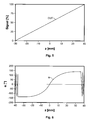
- Figure 5 shows the path of the position signal OUT output by the sensor.
- 3D Hall sensors can be operated only in the presence of a sufficiently powerful magnetic field. If the permanent magnet is located outside the detection range of the sensor, no sensor signal is available any longer.
- clamping voltages are not flexible enough for specific technical applications because they are fixedly preset and do not depend on the current measurement value.
- such fixedly set clamped measurement values are unsuitable when the sensor loses the magnetic field at the centre of the dynamic range, as occurs, for example, in H-bridge circuits in the automotive sector.
- An object of the present invention is to improve a measurement method and a displacement sensor of the type mentioned so that the displacement sensor can be used for a substantially greater deflection range and has optimised precision in a defined part-range of the deflection range without requiring a more powerful magnetic field source.
- the present invention is based on the notion that the magnetic field sensor is further provided with a storage unit which allows a valid sensor signal to be further output when the control by the magnetic field source is lost.
- the last position value still determined reliably is stored and output until the permanent magnet has moved again so far in the direction towards the sensor that it produces a sufficiently powerful magnetic field therein.
- the sensor according to the invention then outputs current measurement values again in place of the stored value.
- the senor according to the invention outputs a valid output signal at all times, it can theoretically be used for displacement paths of any size without subsequent hardware and software being disrupted by the signal which is outside permissible values.
- the measurement range actually involved is only relatively small, it is further possible to dispense with the selection of an unnecessarily large magnet which would be in a position to cover the entire displacement range.
- the advantages according to the invention can be achieved particularly readily if a two or three-dimensional Hall sensor is used as the magnetic field sensor and the magnetic field source comprises at least one permanent magnet.
- the magnitude of the magnetic flux density is monitored at the location of the sensor, it is possible in a particularly simple and efficient manner to determine the state in which the magnetic field source has reached an excessively large distance from the magnetic field sensor to still ensure a satisfactory signal-to-noise ratio. Since the sensor detects the individual magnetic field flux density components in any case, no additional technical measurement complexity is necessary for calculating the magnitude of the magnetic flux density, but instead only a calculation needs to be carried out.
- a displacement sensor arrangement is shown in Figure 1 .
- a Hall sensor 100 is mounted in a fixed position whilst a permanent magnet 102 is supported in a linearly movable manner in relation to the Hall sensor 100.
- the permanent magnet 102 is polarised in such a manner that its north/south axis is orientated parallel with the direction of movement. In principle, however, the principles of the present invention may also be applied to arrangements in which the permanent magnet 102 is polarised in such a manner that its north/south axis extends transversely to the direction of movement.
- the permanent magnet 102 can be displaced out of the zero position shown in Figure 1 in two directions by a displacement path 104 determined by the respective application.
- the Hall sensor 100 detects at least two orthogonal magnetic field components - one which extends along the movement line and one which extends transversely thereto (see Figure 2 ).
- Vector addition of the two components provides the magnitude of the magnetic field
- the angle ⁇ is defined as the angle which is enclosed by the total magnetic field vector
- the calculated angle ⁇ is linearised in order to be available as a displacement-proportional output signal OUT, as illustrated in Figures 4 and 5 .
- the principles according to the invention may also be transferred to other magnetic field sources, for example, electromagnets, and to other magnetic field sensors, such as magnetoresistive sensors or inductive sensors.
- the values of the magnetic field in the direction of movement Bz and, on the other hand, the values of the magnetic field transversely to the direction of movement By are used as the magnetic field components which are measured in accordance with the position of the permanent magnet 102 in the magnetic field sensor, in this instance a Hall sensor 100.
- the values Bx extending orthogonally to By can also be used for the calculation.
- Figure 6 shows the angle ⁇ calculated according to equation (1) for a more extensive displacement range between -40 and +40 mm for the arrangement of Figure 1 , in which the 3D Hall sensor 100 is positioned at the centre of the measurement path to be detected.
- the magnitude of the magnetic control field
- is at a maximum.
- the magnetic control field becomes very weak so that the values for By and Bz for calculating the angle become very small and accordingly the signal-to-noise ratio of both values becomes unfavourable for the calculation. This results in a great variation up to an oscillation of the value ⁇ at the measurement range ends, as illustrated in Figure 6 .
- is continuously monitored in many known sensors. If a value falls below a minimum value, the sensor signal is switched off or a value outside the admissible characteristic line range is output. This is illustrated in Figure 7 . In this instance, the sensor is switched off for a range z ⁇ -35 mm and z > +35 mm and the displacement position of the magnet can no longer be illustrated.
- the signal-to-noise ratios of the magnetic flux densities By or Bz therefore delimit the maximum possible displacement range of the magnet in those known sensors because the components of the magnetic flux density still have to be large enough to supply a meaningful measurement signal. Accordingly, the present invention proposes a 3D Hall sensor 102 having a storage unit 106.
- the output characteristic line can be produced in a substantially simpler manner and with a substantially smaller permanent magnet 102 by the sensor 100 being positioned directly in the partial measurement range between MBA and TMB1 and the movable magnet being configured to be only so large that its control field is sufficiently powerful for this partial measurement range.
- the sensor 100 has a storage device 106 which is in a position to function as a latch for storing the last current value ⁇ before the magnet leaves the detection range.
- the linearised output value OUT which may optionally be further processed in another manner can also be stored.
- the sensor outputs this value until the magnet 102 is brought back into the detection range of the sensor 100.
- the 3D Hall sensor 100 according to the invention is supplemented by a storage function of the last output value so that displacement ranges of the magnet which are infinitely large in theory are possible in the measurement arrangement with the sensor nevertheless behaving in a stable manner.
- Figure 10 shows the behaviour of the angle ⁇ with an extended displacement range of the magnet.
- the magnet leaving the detection range is evaluated by means of the magnitude of the flux density
- a delimitation to greater threshold values Bmin has the advantage that the signal-to-noise ratio is greater and the risk of disruptions is lower but has the disadvantage that the actual dynamic measurement range is narrower.
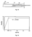
- Figure 15 shows a sensor arrangement which allows a precise measurement of the retraction position for controlling an end position in cylinder applications.
- the movable magnet 102 is secured to the cylinder piston 108 in this instance.
- the sensor 100 is located in the region of the end position which constitutes the measurement range which is really of interest.
- FIG. 17 and 18 Another advantageous application of the sensor arrangement according to the invention is illustrated in Figures 17 and 18 for the precise measurement of a central position or neutral position of selection levers.
- the displacement path of the permanent magnet 102 extends over a circular arc 110 in this instance, the selection lever 112 being connected to the permanent magnet 102.
- the sensor 100 is secured in such a manner that it is nearest the movable magnet 102 when the selection lever 112 is located in the zero position to be detected.
- the displacement path can extend, for example, in a range from -90° to +90° for the angle ⁇ .
- a comparatively small magnet 102 extends around it if valid measurement values are transmitted to subsequent electronic evaluation units in the edge regions which are not of interest in principle. This is carried out according to the invention in that the last measurement value before leaving the defined measurement range is stored and is output for the entire remaining displacement range.
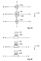
- FIG. 19 to 23 Another advantageous application is shown in Figures 19 to 23 .
- the arrangement according to the invention may also be used in an advantageous manner for precisely measuring a neutral position of H-bridge circuits in a car.
- an individual control magnet 102A, 102B, 102C is used for each gap.
- the sensor 100 stores the current value in the range of the central position until the magnet of the neighbouring gap is detected.
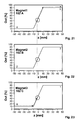
- the associated measurement signals are shown in Figures 21 to 23 .
- a hypothetical switching path from reverse gear R to 5 th gear 5 is schematically shown by a discontinuous line: first, the sensor 100 does not measure any magnetic field at all and therefore outputs as the output signal the last valid measurement value (produced by the magnet 102C). During further displacement in a positive z direction, the control field becomes large enough owing to the magnet 102C for the sensor 100 to output currently measured values. If the gap changes, the entire magnet arrangement of Figure 19 now moves in the x direction so that the B field measured at the sensor 100 falls below the threshold value
- the senor according to the invention has the advantage that it measures in a substantially more precise manner in a small partial measurement range but supplies measurement values which are valid over the entire displacement range to subsequent units and consequently can be used in a substantially broader environment. Furthermore, substantially smaller control magnets are sufficient for achieving the measurement objective. Furthermore, the storage function according to the invention also affords the possibility of storing any values which have currently been measured before the sensor has lost control by means of the magnetic field source even if that stored value is not at the upper or lower end of the measurement values occurring.
Landscapes
- Physics & Mathematics (AREA)
- General Physics & Mathematics (AREA)
- Transmission And Conversion Of Sensor Element Output (AREA)
- Measuring Magnetic Variables (AREA)
- Measurement Of Length, Angles, Or The Like Using Electric Or Magnetic Means (AREA)
Description
- The present invention relates to a method for contactlessly measuring a relative position of a magnetic field source which produces a magnetic field and a magnetic field sensor in relation to each other. The present invention further also relates to a corresponding displacement sensor. The invention describes an operating principle of a sensor which is based on the Hall effect and which achieves an increase in the sensor output range with a magnet which is simultaneously reduced in size by storing the earlier value when control by the magnetic field is lost.
- By means of the method according to the invention, in particular linear movements are intended to be detected and evaluated contactlessly by means of magnetic interaction between one or more permanent magnets and a magnetic sensor based on the Hall effect.
- The measurement of linear movements is used, for example, for controlling machine tools, in pneumatics, in automation technology and robotics and in the automotive sector. A contactless detection of movements affords the advantage inter alia of freedom from wear. The optical and magnetic methods are the most widespread among the contactless measurement methods. Whilst the optical methods ensure a very high level of precision owing to the small wavelength of light, magnetic methods are far less sensitive to dirt and damage, in particular in that magnets and sensor components can be completely enclosed in a non-magnetic hermetic casing.
- There are marketed by various producers displacement sensor systems in which the position of a displaceable permanent magnet is established by means of a two or three-dimensional Hall sensor.
- In order to detect the relative linear movements at a location, two mutually perpendicular magnetic field components are measured and their quotient is evaluated to detect the position. This method has the advantage that, in regions in which a field component assumes an extreme value and therefore does not detect small displacements, the other field component reacts all the more strongly to displacements so that a substantially equally high level of measurement precision is provided in the complete measurement range.
- Furthermore, this principle has the advantage that it is comparatively not very sensitive to a change in the absolute magnetic field strength because proportional numbers between the field components are used to detect the position.
- European Patent specification
EP 0979988 B1 discloses measurement methods for contactless magnetic detection of relative linear movements between permanent magnets and electronic sensors. In order to detect the relative linear movements by means of the electronic sensors, there are detected at a position two mutually perpendicular field components whose quotient is evaluated in order to detect the position. - In a second method variant, the known measurement method can also be carried out in such a manner that, in order to detect the relative linear movements by means of the electronic sensors, there are detected at two locations two mutually perpendicular field components whose quotient is evaluated in order to detect the position.
- The published European Patent Application
EP2159546 A2 discloses a measurement method for the contactless detection of relative linear movements between a sensor arrangement for detecting two mutually perpendicular magnetic field components (R, A) and a permanent magnet. A two or three-dimensional Hall sensor is used in place of individual sensors for detecting various field components. The quasi linear position measurement line is formed by the function U = y - e + g, where y is the functional relationship of the field components and e and g are predeterminable voltage values. In particular, a quasi linear position measurement line U = f(y) is formed from the output signals of the Hall sensor according to the relationship y = a + b·R / f(c·Rn + d·An), where R is the radial field component, A is the axial field component, U is the measurement voltage and a, b, c, d and n are constant factors. - The published European Patent Application
EP1243897 A1 relates to a magnetic displacement sensor which comprises a magnetic field source and a magnetic field sensor which can be displaced relative to each other along a predetermined path. The magnetic field sensor measures two components of the magnetic field produced by the magnetic field source. There is then derived from the measured components a position signal which constitutes the relative position of the magnetic field sensor and magnetic field source. The explanations set out in this publication in respect of the displacement sensor are distinguished in that the establishment of the position signal contains a division of the two measured components of the magnetic field. - However, those known methods have the disadvantage that the magnetic control field becomes very weak at the ends of the measurement range so that the components of the magnetic flux density used to calculate the position assume small values and therefore the signal-to-noise ratio of both values becomes unfavourable for the calculation.
-
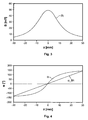
Figure 1 shows an arrangement in which aHall sensor 100 is arranged in a fixed position in order to contactlessly detect a linear movement and the magnetic field of a movablepermanent magnet 102 is detected. In accordance with the north/south polarisation in the direction of movement of thepermanent magnet 102, the magnetic field extending in the direction of movement is subsequently designated to be the magnetic field component Bz and the component extending transversely thereto is subsequently designated By. -
Figure 2 shows the path of the components By and Bz of the magnetic flux density in accordance with the location z at which thepermanent magnet 102 is located. The zero position is the position at which thepermanent magnet 102 and thesensor 100 are directly opposite each other. - The angle α which can be calculated in accordance with the following equation (1) is generally used as the measurement signal.

- The path of the magnitude |
B | of the magnetic flux density is shown inFigure 3 as a function of the location z. The vector magnitude |B | of the magnetic flux density is calculated in known manner from the individual components By and Bz in accordance with the following equation (2). Corresponding calculation rules apply as is conventional for the person skilled in the art when using other coordinate systems or when including a third magnetic field component Bx.
- As illustrated in
Figure 4 , the angle α depends comparatively linearly on the position of thepermanent magnet 102 up to a given limit value in relation to theHall sensor 100. The currently measured characteristic line is generally further linearised, as illustrated inFigure 4 by means of the line α_lin. That linearised line α_lin then forms the output characteristic line of the sensor.Figure 5 shows the path of the position signal OUT output by the sensor. - Most commercially conventional 3D Hall sensors can be operated only in the presence of a sufficiently powerful magnetic field. If the permanent magnet is located outside the detection range of the sensor, no sensor signal is available any longer.
- There are further known arrangements in which a so-called "clamping", that is to say, omission of the measurement values at the measurement range edge, is carried out. A fixedly predetermined value independent of the current measurement is output in place of the actual measurement values which are no longer reliable. The US patent specification
US 6,502,544 B2 describes such a Hall sensor for a throttle valve arrangement in which the sensor signals are set to the lower or upper clamping voltage which constitutes the minimum or maximum possible output voltage of the sensor, respectively. - However, such clamping voltages are not flexible enough for specific technical applications because they are fixedly preset and do not depend on the current measurement value. In particular, such fixedly set clamped measurement values are unsuitable when the sensor loses the magnetic field at the centre of the dynamic range, as occurs, for example, in H-bridge circuits in the automotive sector.
- An object of the present invention is to improve a measurement method and a displacement sensor of the type mentioned so that the displacement sensor can be used for a substantially greater deflection range and has optimised precision in a defined part-range of the deflection range without requiring a more powerful magnetic field source.
- This object is achieved by the subject-matter of the independent patent claims. The dependent claims relate to advantageous developments of the method and displacement sensor according to the invention.
- The present invention is based on the notion that the magnetic field sensor is further provided with a storage unit which allows a valid sensor signal to be further output when the control by the magnetic field source is lost. In particular, the last position value still determined reliably is stored and output until the permanent magnet has moved again so far in the direction towards the sensor that it produces a sufficiently powerful magnetic field therein. The sensor according to the invention then outputs current measurement values again in place of the stored value.
- Since the sensor according to the invention outputs a valid output signal at all times, it can theoretically be used for displacement paths of any size without subsequent hardware and software being disrupted by the signal which is outside permissible values. For applications in which, although the displacement path is relatively large, the measurement range actually involved is only relatively small, it is further possible to dispense with the selection of an unnecessarily large magnet which would be in a position to cover the entire displacement range.
- The advantages according to the invention can be achieved particularly readily if a two or three-dimensional Hall sensor is used as the magnetic field sensor and the magnetic field source comprises at least one permanent magnet.
- If the magnitude of the magnetic flux density is monitored at the location of the sensor, it is possible in a particularly simple and efficient manner to determine the state in which the magnetic field source has reached an excessively large distance from the magnetic field sensor to still ensure a satisfactory signal-to-noise ratio. Since the sensor detects the individual magnetic field flux density components in any case, no additional technical measurement complexity is necessary for calculating the magnitude of the magnetic flux density, but instead only a calculation needs to be carried out.
- For a better understanding of the present invention, it is explained in greater detail with reference to the embodiments illustrated in the following Figures. Identical components are indicated using the same reference numerals and the same component designations. Furthermore, individual features or feature combinations from the embodiments shown and described may also constitute independent solutions which are inventive per se or solutions according to the invention.
- In the drawings:
-
Figure 1 shows a displacement sensor whose signal can be evaluated according to the present invention; -
Figure 2 shows the path of the magnetic field components produced in accordance with the position of the permanent magnet; -
Figure 3 shows the path of the magnitude of the magnetic flux calculated from the magnetic field components produced; -
Figure 4 shows the path of the angle α calculated from the magnetic field components produced and the path of a linearised angle; -
Figure 5 shows the path of the output signal of the sensor as a function of the position; -
Figure 6 shows the path of the angle α for displacement paths outside the actual measurement range; -
Figure 7 is an illustration of the output signal of a sensor without a storage unit during operation with a large displacement path; -
Figure 8 is a schematic illustration of a sensor arrangement for detecting an edge region of the measurement range; -
Figure 9 is a schematic illustration of a sensor arrangement according to the present invention for efficiently detecting a part-measurement range at the edge of the displacement range; -
Figure 10 shows the path of the calculated angle α for relatively large displacement paths z; -
Figure 11 is an illustration of the path of the magnitude of the magnetic flux density belonging toFigure 10 ; -
Figure 12 is a schematic illustration of the stored angular values using the present invention; -
Figure 13 is an illustration of the output values calculated from the angular values ofFigure 12 ; -
Figure 14 is an illustration of the output values in accordance with the position for various threshold values of the magnetic flux density; -
Figure 15 is a schematic illustration of a measurement arrangement for precisely measuring the retraction position in a cylinder application; -
Figure 16 shows the output signal output for the arrangement ofFigure 15 in accordance with the displacement path; -
Figure 17 is a schematic illustration of a measurement arrangement for precisely measuring a central position of selection levers; -
Figure 18 shows the path of the output signal in accordance with the angle ϕ for the arrangement ofFigure 17 ; -
Figure 19 is a view from below of a measurement arrangement for detecting the neutral position of an H-bridge circuit; -
Figure 20 shows side views of the individual gaps for the arrangement ofFigure 19 ; -
Figure 21 shows the output signal of the sensor in accordance with the position of the first magnet; -
Figure 22 shows the output signal of the sensor in accordance with the position of the second magnet; -
Figure 23 shows the output signal of the sensor in accordance with the position of the third magnet. - The invention is now intended to be explained in greater detail below with reference to the Figures.
- A displacement sensor arrangement according to a first embodiment is shown in
Figure 1 . AHall sensor 100 is mounted in a fixed position whilst apermanent magnet 102 is supported in a linearly movable manner in relation to theHall sensor 100. Thepermanent magnet 102 is polarised in such a manner that its north/south axis is orientated parallel with the direction of movement. In principle, however, the principles of the present invention may also be applied to arrangements in which thepermanent magnet 102 is polarised in such a manner that its north/south axis extends transversely to the direction of movement. Thepermanent magnet 102 can be displaced out of the zero position shown inFigure 1 in two directions by adisplacement path 104 determined by the respective application. TheHall sensor 100 detects at least two orthogonal magnetic field components - one which extends along the movement line and one which extends transversely thereto (seeFigure 2 ). Vector addition of the two components provides the magnitude of the magnetic field |B |, as illustrated inFigure 3 . The angle α is defined as the angle which is enclosed by the total magnetic field vector |B | with the perpendicular relative to the direction of movement. - As already mentioned, the angle α is calculated from the magnetic field components in or transversely relative to the direction of movement according to equation (1):

- The calculated angle α is linearised in order to be available as a displacement-proportional output signal OUT, as illustrated in
Figures 4 and5 . - Naturally, the principles according to the invention may also be transferred to other magnetic field sources, for example, electromagnets, and to other magnetic field sensors, such as magnetoresistive sensors or inductive sensors.
- In the present description, on the one hand, the values of the magnetic field in the direction of movement Bz and, on the other hand, the values of the magnetic field transversely to the direction of movement By are used as the magnetic field components which are measured in accordance with the position of the
permanent magnet 102 in the magnetic field sensor, in this instance aHall sensor 100. Naturally, the values Bx extending orthogonally to By can also be used for the calculation. -
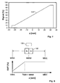
Figure 6 shows the angle α calculated according to equation (1) for a more extensive displacement range between -40 and +40 mm for the arrangement ofFigure 1 , in which the3D Hall sensor 100 is positioned at the centre of the measurement path to be detected. At the position z = 0, the magnitude of the magnetic control field |B | is at a maximum. At the measurement range ends (in this instance: at z values of more than +35 or -35 mm), the magnetic control field becomes very weak so that the values for By and Bz for calculating the angle become very small and accordingly the signal-to-noise ratio of both values becomes unfavourable for the calculation. This results in a great variation up to an oscillation of the value α at the measurement range ends, as illustrated inFigure 6 . - In order to suppress this undesirable behaviour, the magnitude |
B | is continuously monitored in many known sensors. If a value falls below a minimum value, the sensor signal is switched off or a value outside the admissible characteristic line range is output. This is illustrated inFigure 7 . In this instance, the sensor is switched off for a range z < -35 mm and z > +35 mm and the displacement position of the magnet can no longer be illustrated. The signal-to-noise ratios of the magnetic flux densities By or Bz therefore delimit the maximum possible displacement range of the magnet in those known sensors because the components of the magnetic flux density still have to be large enough to supply a meaningful measurement signal. Accordingly, the present invention proposes a3D Hall sensor 102 having astorage unit 106. - For, in many applications, only the precise detection of a portion of the displacement range of the magnet is required whereas the remaining displacement range can be represented in a relatively imprecise manner and the output of a constant valid signal is sufficient in this range. If the sensor is positioned centrally in the entire displacement range for such applications, a comparatively large
permanent magnet 102 having a very powerful control field has to be used so that the signal-to-noise ratio remains sufficiently large for reliable detection over the entire measurement range.Figure 8 shows such an arrangement, with MBA designating the measurement range start, MBE the measurement range end and MBM the measurement range centre. TMB1 shows thepartial measurement range 1 of interest. - By means of the sensor according to the invention, the output characteristic line can be produced in a substantially simpler manner and with a substantially smaller
permanent magnet 102 by thesensor 100 being positioned directly in the partial measurement range between MBA and TMB1 and the movable magnet being configured to be only so large that its control field is sufficiently powerful for this partial measurement range. According to the invention, thesensor 100 has astorage device 106 which is in a position to function as a latch for storing the last current value α before the magnet leaves the detection range. Alternatively or additionally, the linearised output value OUT which may optionally be further processed in another manner can also be stored. - The sensor outputs this value until the
magnet 102 is brought back into the detection range of thesensor 100. In other words: the3D Hall sensor 100 according to the invention is supplemented by a storage function of the last output value so that displacement ranges of the magnet which are infinitely large in theory are possible in the measurement arrangement with the sensor nevertheless behaving in a stable manner. -
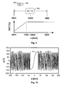
Figure 10 shows the behaviour of the angle α with an extended displacement range of the magnet. The magnet leaving the detection range is evaluated by means of the magnitude of the flux density |B |, as shown inFigure 11 . If the magnitude |B | is smaller than a threshold value for the minimum flux density Bmin, the last valid value of α is stored as the storage value α_latched and is further used for the calculation of the output signal OUT (seeFigure 12 and13 ). - Depending on how narrow the admissible range is selected to be for the magnitude of the B field, the position of the stored values and the width of the remaining linear range change. This is indicated schematically, for example, in
Figure 14 . A delimitation to greater threshold values Bmin has the advantage that the signal-to-noise ratio is greater and the risk of disruptions is lower but has the disadvantage that the actual dynamic measurement range is narrower. - A number of advantageous application examples are intended to be set out below for the storing 3D Hall sensor according to the invention.
-
Figure 15 shows a sensor arrangement which allows a precise measurement of the retraction position for controlling an end position in cylinder applications. Themovable magnet 102 is secured to thecylinder piston 108 in this instance. Thesensor 100 is located in the region of the end position which constitutes the measurement range which is really of interest. - The associated output characteristic line over the location is shown in
Figure 16 . It can clearly be seen that the necessary displacement path is comparatively large at 200 mm but that over a great distance z > TMB1 only the stored final value OUT_latched is output to the connected signal processing unit until themagnet 102, at the position z = TMB1, enters the range in which it produces a sufficiently high magnetic field for thesensor 100. According to the invention, the sensor again outputs actually measured values in place of the stored value OUT_latched. - Another advantageous application of the sensor arrangement according to the invention is illustrated in
Figures 17 and 18 for the precise measurement of a central position or neutral position of selection levers. The displacement path of thepermanent magnet 102 extends over acircular arc 110 in this instance, theselection lever 112 being connected to thepermanent magnet 102. Thesensor 100 is secured in such a manner that it is nearest themovable magnet 102 when theselection lever 112 is located in the zero position to be detected. - As illustrated in
Figure 18 , the displacement path can extend, for example, in a range from -90° to +90° for the angle ϕ. However, only a partial range of a few angular degrees around the zero position has to be detected precisely. A comparativelysmall magnet 102 extends around it if valid measurement values are transmitted to subsequent electronic evaluation units in the edge regions which are not of interest in principle. This is carried out according to the invention in that the last measurement value before leaving the defined measurement range is stored and is output for the entire remaining displacement range. - Another advantageous application is shown in
Figures 19 to 23 . The arrangement according to the invention may also be used in an advantageous manner for precisely measuring a neutral position of H-bridge circuits in a car. As known in principle, anindividual control magnet Figure 19 , thesensor 100 stores the current value in the range of the central position until the magnet of the neighbouring gap is detected. - The associated measurement signals are shown in
Figures 21 to 23 . A hypothetical switching path from reverse gear R to 5thgear 5 is schematically shown by a discontinuous line: first, thesensor 100 does not measure any magnetic field at all and therefore outputs as the output signal the last valid measurement value (produced by themagnet 102C). During further displacement in a positive z direction, the control field becomes large enough owing to themagnet 102C for thesensor 100 to output currently measured values. If the gap changes, the entire magnet arrangement ofFigure 19 now moves in the x direction so that the B field measured at thesensor 100 falls below the threshold value | Bmin |. Thesensor 100 then outputs the last value measured in the dynamic range of the characteristic line fromFigure 23 until themagnet 102B produces a sufficiently large control field. - In this state, current measurement values of the characteristic line from
Figure 22 can be output temporarily. In the case of further displacement of the magnet arrangement in a negative x direction, the sensor also loses the control by means of thesecond magnet 102B and outputs the last measurement value stored until it is controlled by thethird magnet 102C. Since the magnet arrangement moves in a positive z direction, the output signal OUT first changes over the dynamic range in which measured values are output. If the control magnetic field is lost in the z direction, thesensor 100 outputs the last valid measurement value for all positions over approximately 10 mm. - Therefore, the sensor according to the invention has the advantage that it measures in a substantially more precise manner in a small partial measurement range but supplies measurement values which are valid over the entire displacement range to subsequent units and consequently can be used in a substantially broader environment. Furthermore, substantially smaller control magnets are sufficient for achieving the measurement objective. Furthermore, the storage function according to the invention also affords the possibility of storing any values which have currently been measured before the sensor has lost control by means of the magnetic field source even if that stored value is not at the upper or lower end of the measurement values occurring.
-
100 Hall sensor 102 Permanent magnet 102A, 102B, 102C 104 Displacement path 106 Storage unit 108 Cylinder piston 110 Circular arc 112 Selection lever
Claims (11)
- Method for contactlessly measuring a relative position of a magnetic field source (102) which produces a magnetic field and a magnetic field sensor (100) in relation to each other, wherein the magnetic field source (102) and the magnetic field sensor (100) are movable relative to each other,
wherein the magnetic field sensor (100) detects at least two spatial components (By, Bz) of a magnetic flux density of the magnetic field and a position signal is produced from the measured components, and wherein the method comprises the following steps:calculating the position signal on the basis of a quotient of the two magnetic flux density components,calculating a magnitude of the magnetic flux density and comparing the magnitude with a predetermined threshold value,outputting the current calculated position signal if the magnitude of the magnetic flux density is higher than the threshold value,outputting a preceding stored position signal if the magnitude of the magnetic flux density is smaller than or equal to the threshold value,storing the output position signal. - Method according to claim 1, wherein the magnetic field sensor comprises a two or three-dimensional Hall sensor (100).
- Method according to either of the preceding claims, wherein the magnetic field source comprises at least one permanent magnet (102).
- Method according to any one of the preceding claims, wherein the calculation of the position signal comprises:establishing an angle α according to
 linearising the angle in order to produce a displacement-proportional output signal.
 - Method according to any one of the preceding claims, wherein the calculation of the magnitude of the magnetic flux density is carried out by calculating the vector magnitude from the at least two spatial components (By, Bz) of the magnetic flux density of the magnetic field.
- Method according to any one of the preceding claims, wherein the storage of the position signal comprises the storage of a value of the angle

- Displacement sensor for contactlessly measuring a relative position of a magnetic field source (102) which produces a magnetic field and a magnetic field sensor (100) in relation to each other,
wherein the magnetic field source (102) and the magnetic field sensor (100) are movable relative to each other,
wherein the magnetic field sensor (100) is constructed in such a manner that it detects at least two spatial components (By, Bz) of a magnetic flux density of the magnetic field and produces a position signal from the measured components,
wherein the magnetic field sensor (100) comprises:a control and calculation unit for calculating the position signal on the basis of a quotient of the two magnetic flux density components, and for calculating a magnitude of the magnetic flux density and comparing the magnitude with a predetermined threshold value, wherein the control and calculation unit can be operated in order to output the current calculated position signal if the magnitude of the magnetic flux density is higher than the threshold value and in order to output a preceding stored position signal if the magnitude of the magnetic flux density is smaller than or equal to the threshold value,a storage unit (106) for storing the output position signal. - Displacement sensor according to claim 7, wherein the magnetic field sensor (100) comprises a two or three-dimensional Hall sensor.
- Displacement sensor according to either claim 7 or claim 8, wherein the magnetic field source (102) comprises at least one permanent magnet.
- Displacement sensor according to any one of claims 7 to 9, wherein the magnetic field source (102) produces a magnetic field which is rotationally symmetrical relative to an axis which is defined by a relative linear movement between the magnetic field source and the magnetic field sensor.
- Displacement sensor according to any one of claims 7 to 10, wherein the magnetic field source (102) and the magnetic field sensor (100) are arranged in a zero position so that the magnetic field sensor (100) is fixed in a position at which the magnitude of the magnetic flux density produced by the magnetic field source (102) is smaller than or equal to the threshold value.
Applications Claiming Priority (2)
| Application Number | Priority Date | Filing Date | Title |
|---|---|---|---|
| DE102012203225A DE102012203225A1 (en) | 2012-03-01 | 2012-03-01 | METHOD FOR CONTACTLESS MEASUREMENT OF A RELATIVE POSITION BY MEANS OF A 3D HALL SENSOR WITH MEASUREMENT SIGNAL MEMORY |
| PCT/EP2013/054134 WO2013127984A1 (en) | 2012-03-01 | 2013-03-01 | Method for contactlessly measuring a relative position by means of a 3d hall sensor having measurement signal store |
Publications (2)
| Publication Number | Publication Date |
|---|---|
| EP2820384A1 EP2820384A1 (en) | 2015-01-07 |
| EP2820384B1 true EP2820384B1 (en) | 2015-08-12 |
Family
ID=47891626
Family Applications (1)
| Application Number | Title | Priority Date | Filing Date |
|---|---|---|---|
| EP13709809.1A Active EP2820384B1 (en) | 2012-03-01 | 2013-03-01 | Method for contactlessly measuring a relative position by means of a 3d hall sensor having measurement signal store |
Country Status (6)
| Country | Link |
|---|---|
| US (1) | US9618318B2 (en) |
| EP (1) | EP2820384B1 (en) |
| JP (1) | JP6113197B2 (en) |
| CN (1) | CN104204730B (en) |
| DE (1) | DE102012203225A1 (en) |
| WO (1) | WO2013127984A1 (en) |
Families Citing this family (29)
| Publication number | Priority date | Publication date | Assignee | Title |
|---|---|---|---|---|
| DE102012205903B4 (en) | 2012-04-11 | 2014-01-30 | Tyco Electronics Amp Gmbh | METHOD FOR CONTACTLESSLY MEASURING A RELATIVE POSITION BY MEANS OF A MAGNETIC FIELD SENSOR ARRAY TO HALLE EFFECT BASE AND TRANSMITTER |
| JP5595613B1 (en) * | 2014-03-20 | 2014-09-24 | 三菱重工業株式会社 | Gear phase calculation device, gear phase calculation method, and gear machining device |
| DE102014205566A1 (en) | 2014-03-26 | 2015-10-01 | Robert Bosch Gmbh | Sensor arrangement for path detection on a moving component |
| GB2532787A (en) | 2014-11-28 | 2016-06-01 | Ibm | Sensor arrangement for position sensing |
| CN107810389B (en) * | 2015-06-11 | 2021-04-16 | 费斯托股份两合公司 | Drive device and method with detection device |
| FR3039269B1 (en) * | 2015-07-21 | 2017-08-11 | Electricfil Automotive | SENSOR FOR MEASURING THE ABSOLUTE POSITION OF A MOBILE |
| JP6030199B1 (en) * | 2015-08-28 | 2016-11-24 | 栄通信工業株式会社 | Linear sliding potentiometer |
| CN106524887B (en) * | 2015-09-14 | 2019-04-19 | 上海汽车集团股份有限公司 | The method and device of Hall sensor measurement displacement |
| US20190178683A1 (en) | 2016-05-17 | 2019-06-13 | Kongsberg Inc. | System, Method And Object For High Accuracy Magnetic Position Sensing |
| DE102016110968B4 (en) * | 2016-06-15 | 2019-05-02 | Sick Ag | sensor |
| KR101963106B1 (en) | 2016-11-29 | 2019-04-01 | 주식회사 해치텍 | Apparatus for detecting an angle of rotation |
| JP6291638B1 (en) * | 2016-12-07 | 2018-03-14 | 小野 瑞絵 | Magnetic force measuring device |
| FR3070486A1 (en) * | 2017-08-31 | 2019-03-01 | Valeo Systemes De Controle Moteur | METHOD FOR CALIBRATING A MAGNETIC DEVICE FOR DETERMINING THE POSITION OF A PART IN TRANSLATION |
| DE102017128548A1 (en) * | 2017-12-01 | 2019-06-06 | Sick Ag | sensor |
| WO2019139613A1 (en) | 2018-01-12 | 2019-07-18 | Honeywell International Inc. | Magnetic encoding for smart position sensor range extension |
| CN108917720B (en) * | 2018-05-15 | 2020-07-03 | 天津大学 | Pipeline pitch angle measuring device and measuring method |
| US11532470B2 (en) * | 2018-11-27 | 2022-12-20 | Taiwan Semiconductor Manufacturing Company Ltd. | Analyzing method |
| JP6992771B2 (en) * | 2019-01-29 | 2022-01-13 | Tdk株式会社 | Magnetic unit, position detector and magnetic member |
| JP2020144086A (en) * | 2019-03-08 | 2020-09-10 | ジオマテック株式会社 | Fluid residual amount detection device and fluid container |
| DE102019112572A1 (en) * | 2019-05-14 | 2020-11-19 | HELLA GmbH & Co. KGaA | Device and method for the contactless determination of a position of a pedal |
| US20230114412A1 (en) | 2020-02-11 | 2023-04-13 | Brp Megatech Industries Inc. | Magnetoelastic Torque Sensor With Local Measurement Of Ambient Magnetic Field |
| DE102020104297A1 (en) | 2020-02-19 | 2021-08-19 | Kiekert Aktiengesellschaft | Motor vehicle locking device |
| CN111322991B (en) * | 2020-04-16 | 2021-07-20 | 赤峰华源新力科技有限公司 | System for measuring wind power tower cylinder inclination angle based on three-dimensional Hall sensor |
| WO2022041007A1 (en) * | 2020-08-26 | 2022-03-03 | 深圳市大疆创新科技有限公司 | Measuring method and measuring device for rotation angle of rotor of electric motor, and electric motor, gimbal and unmanned aerial vehicle |
| CN112229314A (en) * | 2020-11-13 | 2021-01-15 | 广州市雅江光电设备有限公司 | Method for positioning middle point of induction zone of Hall element |
| CN112985353B (en) * | 2021-05-20 | 2021-09-07 | 浙江图维科技股份有限公司 | Cable anti-settlement displacement monitoring method and system based on electromagnetic detection |
| CN113776416B (en) * | 2021-08-27 | 2024-02-06 | 浙江沃德尔科技集团股份有限公司 | Detection device for non-contact pedal position resisting magnetic field interference |
| CN116045798A (en) * | 2022-07-30 | 2023-05-02 | 荣耀终端有限公司 | Angle detection device, electronic equipment and angle detection method |
| EP4391383A1 (en) * | 2022-12-23 | 2024-06-26 | Melexis Bulgaria EOOD | Magnetic switch and proximity sensing |
Family Cites Families (17)
| Publication number | Priority date | Publication date | Assignee | Title |
|---|---|---|---|---|
| US4606008A (en) * | 1983-07-25 | 1986-08-12 | Cain Encoder Company | Angular position detector |
| US5442283A (en) * | 1993-09-03 | 1995-08-15 | Allegro Microsystems, Inc. | Hall-voltage slope-activated sensor |
| DE19836599A1 (en) | 1998-08-13 | 2000-02-17 | Windhorst Beteiligungsgesellsc | Process for the contactless magnetic detection of linear relative movements between permanent magnets and electronic sensors |
| JP3491587B2 (en) | 1999-12-21 | 2004-01-26 | 株式会社デンソー | Fail mode adjustment method of rotation angle detection sensor |
| JP4936299B2 (en) * | 2000-08-21 | 2012-05-23 | メレクシス・テクノロジーズ・ナムローゼフェンノートシャップ | Magnetic field direction detection sensor |
| EP1243897B1 (en) * | 2001-03-23 | 2013-12-18 | Melexis Technologies NV | Magnetic position sensor |
| WO2003081182A1 (en) * | 2002-03-22 | 2003-10-02 | Asahi Kasei Emd Corporation | Angle determining apparatus and angle determining system |
| CN100443913C (en) * | 2002-11-13 | 2008-12-17 | 松下电器产业株式会社 | Magnetic field sensor ,magnetic field detection device and method |
| GB0305352D0 (en) * | 2003-03-08 | 2003-04-16 | Melexis Nv | Hall effect sensor |
| FR2935478B1 (en) * | 2008-08-28 | 2010-09-10 | Roulements Soc Nouvelle | SYSTEM AND METHOD FOR MEASURING THE AXIAL MOTION OF A ROTATING MOBILE WORKPIECE |
| DE102008045177A1 (en) | 2008-08-30 | 2010-03-04 | Festo Ag & Co. Kg | Measuring method for the contactless detection of linear relative movements between a sensor arrangement and a permanent magnet |
| EP2166312B2 (en) * | 2008-09-18 | 2020-01-15 | Sick Ag | Magnetic or inductive waypoint sensor |
| DE102009028170A1 (en) * | 2009-07-31 | 2011-02-10 | Robert Bosch Gmbh | Commutated electric drive and method for controlling a commutated electric motor |
| DE102010003292A1 (en) * | 2010-03-25 | 2011-09-29 | Fraunhofer-Gesellschaft zur Förderung der angewandten Forschung e.V. | Sensor arrangement and method for determining a magnetization device of a transmitter magnet |
| US8335659B2 (en) * | 2010-07-15 | 2012-12-18 | Tyco Electronics Corporation | Linear position sensor system |
| JP5594086B2 (en) * | 2010-11-19 | 2014-09-24 | アイシン精機株式会社 | Displacement detector |
| DE102012205903B4 (en) * | 2012-04-11 | 2014-01-30 | Tyco Electronics Amp Gmbh | METHOD FOR CONTACTLESSLY MEASURING A RELATIVE POSITION BY MEANS OF A MAGNETIC FIELD SENSOR ARRAY TO HALLE EFFECT BASE AND TRANSMITTER |
-
2012
- 2012-03-01 DE DE102012203225A patent/DE102012203225A1/en not_active Withdrawn
-
2013
- 2013-03-01 JP JP2014559237A patent/JP6113197B2/en active Active
- 2013-03-01 CN CN201380016198.6A patent/CN104204730B/en active Active
- 2013-03-01 US US14/381,911 patent/US9618318B2/en active Active
- 2013-03-01 EP EP13709809.1A patent/EP2820384B1/en active Active
- 2013-03-01 WO PCT/EP2013/054134 patent/WO2013127984A1/en active Application Filing
Also Published As
| Publication number | Publication date |
|---|---|
| US20150046117A1 (en) | 2015-02-12 |
| JP6113197B2 (en) | 2017-04-12 |
| CN104204730B (en) | 2016-08-17 |
| DE102012203225A1 (en) | 2013-09-05 |
| CN104204730A (en) | 2014-12-10 |
| JP2015512040A (en) | 2015-04-23 |
| WO2013127984A1 (en) | 2013-09-06 |
| EP2820384A1 (en) | 2015-01-07 |
| US9618318B2 (en) | 2017-04-11 |
Similar Documents
| Publication | Publication Date | Title |
|---|---|---|
| EP2820384B1 (en) | Method for contactlessly measuring a relative position by means of a 3d hall sensor having measurement signal store | |
| US9982988B2 (en) | Displacement sensor for contactlessly measuring a relative position by means of a magnetic field sensor array on the basis of the hall effect | |
| US9360537B2 (en) | Method for contactless measurement of a relative position by means of a hall sensor | |
| US9335149B2 (en) | Displacement sensor for contactlessly measuring a position by means of a plurality of magnetic field sensors arranged in series | |
| CN102954807B (en) | Magnetic position sensor, system and method | |
| US8970210B2 (en) | Bidirectional magnetic position sensor having field rotation | |
| US9835472B2 (en) | Using cartesian coordinates for position detection with a magnetic sensor | |
| US10571305B2 (en) | Method for determining the position of a magnet relative to a row of sensors | |
| CN104422386A (en) | Rotation detector | |
| EP2843358A1 (en) | Magnet device and position sensing system | |
| WO2015063138A1 (en) | Temperature compensation method of magnetic control fields in a hall sensor with os adaption | |
| US20130241575A1 (en) | Electric machine | |
| US20120242332A1 (en) | Measurement method and magnetic sensor for the contactless detection of movements | |
| CN116718962A (en) | Measuring system | |
| CN115053079A (en) | Position detecting device | |
| CN114391090B (en) | Displacement measuring device with Hall sensor and magnet | |
| CN112985253B (en) | Control lever comprising a single magnetic sensor for torsion angle and tilt angle detection | |
| US10176915B2 (en) | Bistable linear electromagnet | |
| JP2009236743A (en) | Magnetic position detecting device | |
| JP2017219334A (en) | Stroke detector | |
| JP2017116408A (en) | Stroke detection device |
Legal Events
| Date | Code | Title | Description |
|---|---|---|---|
| PUAI | Public reference made under article 153(3) epc to a published international application that has entered the european phase |
Free format text: ORIGINAL CODE: 0009012 |
|
| 17P | Request for examination filed |
Effective date: 20140930 |
|
| AK | Designated contracting states |
Kind code of ref document: A1 Designated state(s): AL AT BE BG CH CY CZ DE DK EE ES FI FR GB GR HR HU IE IS IT LI LT LU LV MC MK MT NL NO PL PT RO RS SE SI SK SM TR |
|
| AX | Request for extension of the european patent |
Extension state: BA ME |
|
| REG | Reference to a national code |
Ref country code: DE Ref legal event code: R079 Ref document number: 602013002644 Country of ref document: DE Free format text: PREVIOUS MAIN CLASS: G01D0005244000 Ipc: G01D0005140000 |
|
| GRAP | Despatch of communication of intention to grant a patent |
Free format text: ORIGINAL CODE: EPIDOSNIGR1 |
|
| RIC1 | Information provided on ipc code assigned before grant |
Ipc: G01B 7/30 20060101ALI20150227BHEP Ipc: G01D 5/244 20060101ALI20150227BHEP Ipc: G01B 7/004 20060101ALI20150227BHEP Ipc: G01D 5/14 20060101AFI20150227BHEP |
|
| DAX | Request for extension of the european patent (deleted) | ||
| INTG | Intention to grant announced |
Effective date: 20150324 |
|
| GRAS | Grant fee paid |
Free format text: ORIGINAL CODE: EPIDOSNIGR3 |
|
| GRAA | (expected) grant |
Free format text: ORIGINAL CODE: 0009210 |
|
| AK | Designated contracting states |
Kind code of ref document: B1 Designated state(s): AL AT BE BG CH CY CZ DE DK EE ES FI FR GB GR HR HU IE IS IT LI LT LU LV MC MK MT NL NO PL PT RO RS SE SI SK SM TR |
|
| REG | Reference to a national code |
Ref country code: GB Ref legal event code: FG4D |
|
| REG | Reference to a national code |
Ref country code: CH Ref legal event code: EP |
|
| REG | Reference to a national code |
Ref country code: AT Ref legal event code: REF Ref document number: 742574 Country of ref document: AT Kind code of ref document: T Effective date: 20150815 |
|
| RAP2 | Party data changed (patent owner data changed or rights of a patent transferred) |
Owner name: TE CONNECTIVITY GERMANY GMBH |
|
| REG | Reference to a national code |
Ref country code: IE Ref legal event code: FG4D |
|
| REG | Reference to a national code |
Ref country code: DE Ref legal event code: R096 Ref document number: 602013002644 Country of ref document: DE |
|
| REG | Reference to a national code |
Ref country code: LT Ref legal event code: MG4D |
|
| REG | Reference to a national code |
Ref country code: AT Ref legal event code: MK05 Ref document number: 742574 Country of ref document: AT Kind code of ref document: T Effective date: 20150812 |
|
| REG | Reference to a national code |
Ref country code: NL Ref legal event code: MP Effective date: 20150812 |
|
| PG25 | Lapsed in a contracting state [announced via postgrant information from national office to epo] |
Ref country code: FI Free format text: LAPSE BECAUSE OF FAILURE TO SUBMIT A TRANSLATION OF THE DESCRIPTION OR TO PAY THE FEE WITHIN THE PRESCRIBED TIME-LIMIT Effective date: 20150812 Ref country code: LT Free format text: LAPSE BECAUSE OF FAILURE TO SUBMIT A TRANSLATION OF THE DESCRIPTION OR TO PAY THE FEE WITHIN THE PRESCRIBED TIME-LIMIT Effective date: 20150812 Ref country code: GR Free format text: LAPSE BECAUSE OF FAILURE TO SUBMIT A TRANSLATION OF THE DESCRIPTION OR TO PAY THE FEE WITHIN THE PRESCRIBED TIME-LIMIT Effective date: 20151113 Ref country code: NO Free format text: LAPSE BECAUSE OF FAILURE TO SUBMIT A TRANSLATION OF THE DESCRIPTION OR TO PAY THE FEE WITHIN THE PRESCRIBED TIME-LIMIT Effective date: 20151112 Ref country code: LV Free format text: LAPSE BECAUSE OF FAILURE TO SUBMIT A TRANSLATION OF THE DESCRIPTION OR TO PAY THE FEE WITHIN THE PRESCRIBED TIME-LIMIT Effective date: 20150812 |
|
| PG25 | Lapsed in a contracting state [announced via postgrant information from national office to epo] |
Ref country code: SE Free format text: LAPSE BECAUSE OF FAILURE TO SUBMIT A TRANSLATION OF THE DESCRIPTION OR TO PAY THE FEE WITHIN THE PRESCRIBED TIME-LIMIT Effective date: 20150812 Ref country code: AT Free format text: LAPSE BECAUSE OF FAILURE TO SUBMIT A TRANSLATION OF THE DESCRIPTION OR TO PAY THE FEE WITHIN THE PRESCRIBED TIME-LIMIT Effective date: 20150812 Ref country code: IS Free format text: LAPSE BECAUSE OF FAILURE TO SUBMIT A TRANSLATION OF THE DESCRIPTION OR TO PAY THE FEE WITHIN THE PRESCRIBED TIME-LIMIT Effective date: 20151212 Ref country code: ES Free format text: LAPSE BECAUSE OF FAILURE TO SUBMIT A TRANSLATION OF THE DESCRIPTION OR TO PAY THE FEE WITHIN THE PRESCRIBED TIME-LIMIT Effective date: 20150812 Ref country code: PL Free format text: LAPSE BECAUSE OF FAILURE TO SUBMIT A TRANSLATION OF THE DESCRIPTION OR TO PAY THE FEE WITHIN THE PRESCRIBED TIME-LIMIT Effective date: 20150812 Ref country code: RS Free format text: LAPSE BECAUSE OF FAILURE TO SUBMIT A TRANSLATION OF THE DESCRIPTION OR TO PAY THE FEE WITHIN THE PRESCRIBED TIME-LIMIT Effective date: 20150812 Ref country code: HR Free format text: LAPSE BECAUSE OF FAILURE TO SUBMIT A TRANSLATION OF THE DESCRIPTION OR TO PAY THE FEE WITHIN THE PRESCRIBED TIME-LIMIT Effective date: 20150812 Ref country code: PT Free format text: LAPSE BECAUSE OF FAILURE TO SUBMIT A TRANSLATION OF THE DESCRIPTION OR TO PAY THE FEE WITHIN THE PRESCRIBED TIME-LIMIT Effective date: 20151214 |
|
| REG | Reference to a national code |
Ref country code: FR Ref legal event code: PLFP Year of fee payment: 4 |
|
| PG25 | Lapsed in a contracting state [announced via postgrant information from national office to epo] |
Ref country code: NL Free format text: LAPSE BECAUSE OF FAILURE TO SUBMIT A TRANSLATION OF THE DESCRIPTION OR TO PAY THE FEE WITHIN THE PRESCRIBED TIME-LIMIT Effective date: 20150812 |
|
| PG25 | Lapsed in a contracting state [announced via postgrant information from national office to epo] |
Ref country code: CZ Free format text: LAPSE BECAUSE OF FAILURE TO SUBMIT A TRANSLATION OF THE DESCRIPTION OR TO PAY THE FEE WITHIN THE PRESCRIBED TIME-LIMIT Effective date: 20150812 Ref country code: EE Free format text: LAPSE BECAUSE OF FAILURE TO SUBMIT A TRANSLATION OF THE DESCRIPTION OR TO PAY THE FEE WITHIN THE PRESCRIBED TIME-LIMIT Effective date: 20150812 Ref country code: DK Free format text: LAPSE BECAUSE OF FAILURE TO SUBMIT A TRANSLATION OF THE DESCRIPTION OR TO PAY THE FEE WITHIN THE PRESCRIBED TIME-LIMIT Effective date: 20150812 Ref country code: SK Free format text: LAPSE BECAUSE OF FAILURE TO SUBMIT A TRANSLATION OF THE DESCRIPTION OR TO PAY THE FEE WITHIN THE PRESCRIBED TIME-LIMIT Effective date: 20150812 |
|
| REG | Reference to a national code |
Ref country code: DE Ref legal event code: R097 Ref document number: 602013002644 Country of ref document: DE |
|
| PG25 | Lapsed in a contracting state [announced via postgrant information from national office to epo] |
Ref country code: RO Free format text: LAPSE BECAUSE OF FAILURE TO SUBMIT A TRANSLATION OF THE DESCRIPTION OR TO PAY THE FEE WITHIN THE PRESCRIBED TIME-LIMIT Effective date: 20150812 |
|
| PLBE | No opposition filed within time limit |
Free format text: ORIGINAL CODE: 0009261 |
|
| STAA | Information on the status of an ep patent application or granted ep patent |
Free format text: STATUS: NO OPPOSITION FILED WITHIN TIME LIMIT |
|
| 26N | No opposition filed |
Effective date: 20160513 |
|
| PG25 | Lapsed in a contracting state [announced via postgrant information from national office to epo] |
Ref country code: SI Free format text: LAPSE BECAUSE OF FAILURE TO SUBMIT A TRANSLATION OF THE DESCRIPTION OR TO PAY THE FEE WITHIN THE PRESCRIBED TIME-LIMIT Effective date: 20150812 Ref country code: BE Free format text: LAPSE BECAUSE OF NON-PAYMENT OF DUE FEES Effective date: 20160331 |
|
| PG25 | Lapsed in a contracting state [announced via postgrant information from national office to epo] |
Ref country code: MC Free format text: LAPSE BECAUSE OF FAILURE TO SUBMIT A TRANSLATION OF THE DESCRIPTION OR TO PAY THE FEE WITHIN THE PRESCRIBED TIME-LIMIT Effective date: 20150812 Ref country code: LU Free format text: LAPSE BECAUSE OF FAILURE TO SUBMIT A TRANSLATION OF THE DESCRIPTION OR TO PAY THE FEE WITHIN THE PRESCRIBED TIME-LIMIT Effective date: 20160301 |
|
| REG | Reference to a national code |
Ref country code: CH Ref legal event code: PL |
|
| REG | Reference to a national code |
Ref country code: IE Ref legal event code: MM4A |
|
| PG25 | Lapsed in a contracting state [announced via postgrant information from national office to epo] |
Ref country code: BE Free format text: LAPSE BECAUSE OF FAILURE TO SUBMIT A TRANSLATION OF THE DESCRIPTION OR TO PAY THE FEE WITHIN THE PRESCRIBED TIME-LIMIT Effective date: 20150812 |
|
| PG25 | Lapsed in a contracting state [announced via postgrant information from national office to epo] |
Ref country code: CH Free format text: LAPSE BECAUSE OF NON-PAYMENT OF DUE FEES Effective date: 20160331 Ref country code: IE Free format text: LAPSE BECAUSE OF NON-PAYMENT OF DUE FEES Effective date: 20160301 Ref country code: LI Free format text: LAPSE BECAUSE OF NON-PAYMENT OF DUE FEES Effective date: 20160331 |
|
| REG | Reference to a national code |
Ref country code: FR Ref legal event code: PLFP Year of fee payment: 5 |
|
| PG25 | Lapsed in a contracting state [announced via postgrant information from national office to epo] |
Ref country code: MT Free format text: LAPSE BECAUSE OF FAILURE TO SUBMIT A TRANSLATION OF THE DESCRIPTION OR TO PAY THE FEE WITHIN THE PRESCRIBED TIME-LIMIT Effective date: 20150812 |
|
| GBPC | Gb: european patent ceased through non-payment of renewal fee |
Effective date: 20170301 |
|
| REG | Reference to a national code |
Ref country code: FR Ref legal event code: PLFP Year of fee payment: 6 |
|
| PG25 | Lapsed in a contracting state [announced via postgrant information from national office to epo] |
Ref country code: GB Free format text: LAPSE BECAUSE OF NON-PAYMENT OF DUE FEES Effective date: 20170301 |
|
| PG25 | Lapsed in a contracting state [announced via postgrant information from national office to epo] |
Ref country code: HU Free format text: LAPSE BECAUSE OF FAILURE TO SUBMIT A TRANSLATION OF THE DESCRIPTION OR TO PAY THE FEE WITHIN THE PRESCRIBED TIME-LIMIT; INVALID AB INITIO Effective date: 20130301 Ref country code: SM Free format text: LAPSE BECAUSE OF FAILURE TO SUBMIT A TRANSLATION OF THE DESCRIPTION OR TO PAY THE FEE WITHIN THE PRESCRIBED TIME-LIMIT Effective date: 20150812 |
|
| PG25 | Lapsed in a contracting state [announced via postgrant information from national office to epo] |
Ref country code: MK Free format text: LAPSE BECAUSE OF FAILURE TO SUBMIT A TRANSLATION OF THE DESCRIPTION OR TO PAY THE FEE WITHIN THE PRESCRIBED TIME-LIMIT Effective date: 20150812 Ref country code: CY Free format text: LAPSE BECAUSE OF FAILURE TO SUBMIT A TRANSLATION OF THE DESCRIPTION OR TO PAY THE FEE WITHIN THE PRESCRIBED TIME-LIMIT Effective date: 20150812 Ref country code: MT Free format text: LAPSE BECAUSE OF FAILURE TO SUBMIT A TRANSLATION OF THE DESCRIPTION OR TO PAY THE FEE WITHIN THE PRESCRIBED TIME-LIMIT Effective date: 20160331 |
|
| PG25 | Lapsed in a contracting state [announced via postgrant information from national office to epo] |
Ref country code: BG Free format text: LAPSE BECAUSE OF FAILURE TO SUBMIT A TRANSLATION OF THE DESCRIPTION OR TO PAY THE FEE WITHIN THE PRESCRIBED TIME-LIMIT Effective date: 20150812 |
|
| PG25 | Lapsed in a contracting state [announced via postgrant information from national office to epo] |
Ref country code: TR Free format text: LAPSE BECAUSE OF FAILURE TO SUBMIT A TRANSLATION OF THE DESCRIPTION OR TO PAY THE FEE WITHIN THE PRESCRIBED TIME-LIMIT Effective date: 20150812 Ref country code: AL Free format text: LAPSE BECAUSE OF FAILURE TO SUBMIT A TRANSLATION OF THE DESCRIPTION OR TO PAY THE FEE WITHIN THE PRESCRIBED TIME-LIMIT Effective date: 20150812 |
|
| PGFP | Annual fee paid to national office [announced via postgrant information from national office to epo] |
Ref country code: IT Payment date: 20200221 Year of fee payment: 8 |
|
| PG25 | Lapsed in a contracting state [announced via postgrant information from national office to epo] |
Ref country code: IT Free format text: LAPSE BECAUSE OF NON-PAYMENT OF DUE FEES Effective date: 20210301 |
|
| PGFP | Annual fee paid to national office [announced via postgrant information from national office to epo] |
Ref country code: DE Payment date: 20231229 Year of fee payment: 12 |
|
| PGFP | Annual fee paid to national office [announced via postgrant information from national office to epo] |
Ref country code: FR Payment date: 20240103 Year of fee payment: 12 |