EP2820351B1 - Led lighting arrangement - Google Patents
Led lighting arrangement Download PDFInfo
- Publication number
- EP2820351B1 EP2820351B1 EP13718385.1A EP13718385A EP2820351B1 EP 2820351 B1 EP2820351 B1 EP 2820351B1 EP 13718385 A EP13718385 A EP 13718385A EP 2820351 B1 EP2820351 B1 EP 2820351B1
- Authority
- EP
- European Patent Office
- Prior art keywords
- light
- group
- light sources
- colour temperature
- lighting arrangement
- Prior art date
- Legal status (The legal status is an assumption and is not a legal conclusion. Google has not performed a legal analysis and makes no representation as to the accuracy of the status listed.)
- Not-in-force
Links
Images

Classifications
-
- F—MECHANICAL ENGINEERING; LIGHTING; HEATING; WEAPONS; BLASTING
- F21—LIGHTING
- F21K—NON-ELECTRIC LIGHT SOURCES USING LUMINESCENCE; LIGHT SOURCES USING ELECTROCHEMILUMINESCENCE; LIGHT SOURCES USING CHARGES OF COMBUSTIBLE MATERIAL; LIGHT SOURCES USING SEMICONDUCTOR DEVICES AS LIGHT-GENERATING ELEMENTS; LIGHT SOURCES NOT OTHERWISE PROVIDED FOR
- F21K9/00—Light sources using semiconductor devices as light-generating elements, e.g. using light-emitting diodes [LED] or lasers
- F21K9/60—Optical arrangements integrated in the light source, e.g. for improving the colour rendering index or the light extraction
- F21K9/64—Optical arrangements integrated in the light source, e.g. for improving the colour rendering index or the light extraction using wavelength conversion means distinct or spaced from the light-generating element, e.g. a remote phosphor layer
-
- F—MECHANICAL ENGINEERING; LIGHTING; HEATING; WEAPONS; BLASTING
- F21—LIGHTING
- F21K—NON-ELECTRIC LIGHT SOURCES USING LUMINESCENCE; LIGHT SOURCES USING ELECTROCHEMILUMINESCENCE; LIGHT SOURCES USING CHARGES OF COMBUSTIBLE MATERIAL; LIGHT SOURCES USING SEMICONDUCTOR DEVICES AS LIGHT-GENERATING ELEMENTS; LIGHT SOURCES NOT OTHERWISE PROVIDED FOR
- F21K9/00—Light sources using semiconductor devices as light-generating elements, e.g. using light-emitting diodes [LED] or lasers
- F21K9/60—Optical arrangements integrated in the light source, e.g. for improving the colour rendering index or the light extraction
- F21K9/62—Optical arrangements integrated in the light source, e.g. for improving the colour rendering index or the light extraction using mixing chambers, e.g. housings with reflective walls
-
- F—MECHANICAL ENGINEERING; LIGHTING; HEATING; WEAPONS; BLASTING
- F21—LIGHTING
- F21V—FUNCTIONAL FEATURES OR DETAILS OF LIGHTING DEVICES OR SYSTEMS THEREOF; STRUCTURAL COMBINATIONS OF LIGHTING DEVICES WITH OTHER ARTICLES, NOT OTHERWISE PROVIDED FOR
- F21V17/00—Fastening of component parts of lighting devices, e.g. shades, globes, refractors, reflectors, filters, screens, grids or protective cages
- F21V17/002—Fastening of component parts of lighting devices, e.g. shades, globes, refractors, reflectors, filters, screens, grids or protective cages with provision for interchangeability, i.e. component parts being especially adapted to be replaced by another part with the same or a different function
-
- F—MECHANICAL ENGINEERING; LIGHTING; HEATING; WEAPONS; BLASTING
- F21—LIGHTING
- F21V—FUNCTIONAL FEATURES OR DETAILS OF LIGHTING DEVICES OR SYSTEMS THEREOF; STRUCTURAL COMBINATIONS OF LIGHTING DEVICES WITH OTHER ARTICLES, NOT OTHERWISE PROVIDED FOR
- F21V17/00—Fastening of component parts of lighting devices, e.g. shades, globes, refractors, reflectors, filters, screens, grids or protective cages
- F21V17/10—Fastening of component parts of lighting devices, e.g. shades, globes, refractors, reflectors, filters, screens, grids or protective cages characterised by specific fastening means or way of fastening
- F21V17/101—Fastening of component parts of lighting devices, e.g. shades, globes, refractors, reflectors, filters, screens, grids or protective cages characterised by specific fastening means or way of fastening permanently, e.g. welding, gluing or riveting
-
- F—MECHANICAL ENGINEERING; LIGHTING; HEATING; WEAPONS; BLASTING
- F21—LIGHTING
- F21V—FUNCTIONAL FEATURES OR DETAILS OF LIGHTING DEVICES OR SYSTEMS THEREOF; STRUCTURAL COMBINATIONS OF LIGHTING DEVICES WITH OTHER ARTICLES, NOT OTHERWISE PROVIDED FOR
- F21V23/00—Arrangement of electric circuit elements in or on lighting devices
- F21V23/06—Arrangement of electric circuit elements in or on lighting devices the elements being coupling devices, e.g. connectors
-
- F—MECHANICAL ENGINEERING; LIGHTING; HEATING; WEAPONS; BLASTING
- F21—LIGHTING
- F21V—FUNCTIONAL FEATURES OR DETAILS OF LIGHTING DEVICES OR SYSTEMS THEREOF; STRUCTURAL COMBINATIONS OF LIGHTING DEVICES WITH OTHER ARTICLES, NOT OTHERWISE PROVIDED FOR
- F21V9/00—Elements for modifying spectral properties, polarisation or intensity of the light emitted, e.g. filters
- F21V9/30—Elements containing photoluminescent material distinct from or spaced from the light source
- F21V9/32—Elements containing photoluminescent material distinct from or spaced from the light source characterised by the arrangement of the photoluminescent material
-
- H—ELECTRICITY
- H10—SEMICONDUCTOR DEVICES; ELECTRIC SOLID-STATE DEVICES NOT OTHERWISE PROVIDED FOR
- H10H—INORGANIC LIGHT-EMITTING SEMICONDUCTOR DEVICES HAVING POTENTIAL BARRIERS
- H10H20/00—Individual inorganic light-emitting semiconductor devices having potential barriers, e.g. light-emitting diodes [LED]
- H10H20/80—Constructional details
- H10H20/85—Packages
- H10H20/851—Wavelength conversion means
-
- F—MECHANICAL ENGINEERING; LIGHTING; HEATING; WEAPONS; BLASTING
- F21—LIGHTING
- F21Y—INDEXING SCHEME ASSOCIATED WITH SUBCLASSES F21K, F21L, F21S and F21V, RELATING TO THE FORM OR THE KIND OF THE LIGHT SOURCES OR OF THE COLOUR OF THE LIGHT EMITTED
- F21Y2113/00—Combination of light sources
- F21Y2113/10—Combination of light sources of different colours
- F21Y2113/13—Combination of light sources of different colours comprising an assembly of point-like light sources
-
- F—MECHANICAL ENGINEERING; LIGHTING; HEATING; WEAPONS; BLASTING
- F21—LIGHTING
- F21Y—INDEXING SCHEME ASSOCIATED WITH SUBCLASSES F21K, F21L, F21S and F21V, RELATING TO THE FORM OR THE KIND OF THE LIGHT SOURCES OR OF THE COLOUR OF THE LIGHT EMITTED
- F21Y2115/00—Light-generating elements of semiconductor light sources
- F21Y2115/10—Light-emitting diodes [LED]
Definitions
- the present invention relates to the field of light emitting diodes, and more specifically to color conversion of light emitting diodes.
- LEDs Light emitting diodes, LEDs, are employed in a wide range of lighting applications. LED light sources are, for example, used to produce white light, and different light qualities are required for different applications. For some applications there is a desire to provide white light having a color temperature of e.g. approximately 2700K, i.e. a warm white light, while for other applications there is a desire to provide white light having a color temperature of e.g. approximately 6000K, i.e. a cool white light.
- a color temperature of e.g. approximately 2700K i.e. a warm white light
- 6000K i.e. a cool white light.
- one approach is to coat blue LED(s) with a phosphor.
- a fraction of the blue light from the blue LED is thereby being transformed by the phosphor from shorter wavelengths to longer wavelengths, thereby producing so-called phosphor based white LEDs.
- the characteristics of the white light e.g. the color temperature, can be changed or varied by providing different phosphor materials.
- the white light characteristics may also be varied by providing different thickness and/or coating of the phosphor.
- LEDs providing white light of different temperature are often used and mixed with each other. For example, an LED providing a cool white light may be combined and mixed with an LED providing a warmer white light.
- US2010/0118374A1 discloses a methodology of maintaining correlated color temperature (CCT) of a light beam from a lighting means by having a processing means to instruct several lighting means groups, wherein each group has different CCT ranges, that are arranged together, to provide a light beam of intended CCT.
- CCT correlated color temperature
- CN102128396A discloses an array of LED lamps arranged on a lamp board.
- a control circuit is connected with the LED lamps.
- the LED lamps include warm white, blue, green, natural white and cold white.
- the warm white LED lamp is arranged on the periphery.
- the LED lamps of the other four colors are uniformly distributed in the central region encircled by the warm white LED lamp.
- the control circuit has a color temperature control circuit for adjusting the color temperature of the LED lamps between 3500 K and 5000 K. Due to the various applications requiring different kind of white light characteristics and inherent variation of performance in relation to manufacturing of semiconductor products, such as LEDs, quite a number of combinations are possible if e.g. a tunable white color temperature is required. Therefore, a problem with the above mentioned approach of combining LEDs having different white light is that many light modules have to be available for achieving a desired combination.
- a lighting arrangement comprising a first group of light sources comprising at least one LED providing white light having a first colour temperature, a second group of light sources comprising at least one LED providing white light having a second colour temperature, and a third group of light sources comprising at least one LED providing a light having a predetermined dominant wavelength; wherein the third group of light sources is configured to receive a light converting device comprising a phosphor, the light converting device configured for converting light from the third group of light sources to white light having a third colour temperature, wherein the light converting device is configured to have electrical connection means for providing an electrical connection between one of the first and the second group of light sources and the third group of light sources.
- the present invention is based on the insight that the lighting arrangement may be provided with a third group of light sources comprising at least one LED providing light having a predetermined dominant wavelength and configured to receive the light converting device having electrical connection means that may be adaptively connected to one of the first or the second group of light sources.
- the total light emitted by the lighting arrangement may thus be controlled and adjusted based on the specific desired output of white colour temperature from the lighting arrangement, by selectively connecting the third group of light sources to be electrically controlled together and in conjunction with either the first or the second group of light sources.
- the colour temperature may be adjusted by configuring the third group, using the predetermined dominant wavelength and the light converting device, to provide a warmer white colour temperature, thereby compensating for the slightly cooler colour temperature of the first group of light sources.
- the phosphor of the light converting device may be selected such that the third colour temperature is warmer (i.e. lower Kelvin) than the first colour temperature.
- the same is of course valid in case of having a first group providing a white colour temperature which is slightly warmer than desired and thereby compensating by configuring the third group of light sources to provide a cooler white colour temperature.
- the total output of white light from the lighting arrangement may be adjusted to fulfil the criteria of desired white light output from the lighting arrangement.
- An advantage is, at least, that the LEDs of the first and the second group may be selected more freely and possibly be compensated in terms of white colour temperature by means of the third group of light sources.
- the present invention is not limited to a specific type and characteristic of the phosphor arranged in the light converting device, i.e. the choice of material, thickness, coating, etc. of the phosphor may be varied depending on e.g. the desired output of white light from the light converting device.
- each of the first and the second group of light sources may also be equipped with at least one LED arranged with a phosphor in order to provide white light having the first and the second colour temperature.
- the characteristics of the phosphor may be different for the first and the second group of light sources in order to provide different white colour temperature.
- the light converting device should be interpreted as forming a part of the lighting arrangement.
- the phosphor arranged in the light converting device may also be configured to convert light to a more or less saturated colour, such as e.g. amber.
- the predetermined dominant wavelength is between 440 - 460 nm, for example provided by means of a blue light source suitable for phosphor conversion.
- the light source of the third group provides UV or violet light.
- the first and the second group of light sources may comprise a plurality of LED modules.
- the plurality of LED modules provided in each of the first and the second group of light sources may provide a white light having essentially the same colour temperature or they may provide a white light having slightly different colour temperature so that they in combination with each other provides a white light having a first and a second colour temperature.
- each of the plurality of LED modules may be electrically connected in series to each other and to the electrical connection means of the light converting device.
- an electrical drive current can be provided through each of the LED modules of the first and the second group of light sources and through the light converting device.
- cold white colour temperature should be interpreted as a white colour having a colour temperature in the range of approximately 3500 - 7000 Kelvin
- warm white colour temperature should be interpreted as a white colour having a colour temperature in the range of approximately 1800 - 3500 Kelvin.
- the light converting device may be provided to the third group of light sources by means of e.g. pressing soldering or gluing.
- the lighting arrangement is preferably provided as a component of an LED module, wherein the LED module further comprises a light mixing device configured to receive light from the lighting arrangement and to provide a mixed light output.
- the light emitted from the LED module may be mixed so that a desired white colour temperature is provided from the LED module.
- the LED module may comprise a control unit for controlling the operation of the first and/or the second group of light sources.
- the control unit may determine and control the mixture of light in order to provide an output white light having a desired colour temperature.
- the lighting arrangement 100 comprises a first group of light sources 102, in the illustrated embodiment depicted as comprising three light sources 104, 104', 104", where each of the light sources 104, 104', 104" comprises at least one LED and are arranged to provide white light having a first colour temperature.
- the first colour temperature will in the following and throughout the remaining description be described as a cold white colour temperature, which should be interpreted as a white colour having a colour temperature in the range of approximately 3500 - 7000 Kelvin.
- the three light sources 104, 104', 104" depicted in Fig. 1 are electrically connected in series with each other by means of electrical wiring 108, e.g. the tracks on a printed circuit board (not shown here), and adapted to be provided with an electrical drive current I CW .
- the lighting arrangement 100 also comprises a second group of light sources 110, in the illustrated embodiment depicted as three light sources 112, 112', 112", where each of the light sources 112, 112', 112" comprises at least one LED and are arranged to provide white light having a second colour temperature.
- the second colour temperature will in the following and throughout the remaining description be described as a warm white colour temperature, which should be interpreted as a white colour having a colour temperature in the range of approximately 1800 - 3500 Kelvin.
- the three light sources 112, 112', 112" of the second group of light sources 110 are electrically connected in series with each other by means of electrical wiring 108', e.g. the tracks on a printed circuit board (not shown here), and adapted to be provided with an electrical drive current I WW .
- the lighting arrangement 100 also comprises a third group of light sources 116.
- the third group of light sources 116 comprises at least one LED 118 providing a light having a predetermined wavelength, which in the following and throughout the remaining description is an LED configured to provide a blue light having a wavelength in the range of e.g. 440 - 460 nm.
- the blue LED 118 is electrically connected to a printed circuit board (not shown here).
- Figs. 2a - 2d illustrating example embodiments of a light converting device 200 for use with the lighting arrangement 100 according to the present invention.
- the light converting device 200 comprises a holder 202, a first 204 and a second 205 set of internal electrical wiring, electrical connecting means 206, and a phosphor 208.
- the light converting device 200 is adapted to be provided to, or combined with, the third group of light sources 116, so that the phosphor 208 arranged in the holder 202 of the light converting device 200 can convert the blue light into a third colour temperature by means of e.g.
- the light converting device 200 illustrated in Fig. 2a is adapted to be provided to, or combined with, the third group of light sources 116 for providing a cold white colour temperature. This is achieved by choosing an appropriate phosphor 208 and powering the third group of light sources 116 in combination with the powering of the first group of light sources 102 by electrically connecting the first set 204 of internal electrical wiring to the first group of light sources 102 such that the third group of light sources 116 is electrically driven in series by the electrical drive current I CW of the first group of light sources 102.
- the second group of light sources 110 is electrically connected to the second set 205 of internal electrical wiring arranged in the light converting device 200 such that the electrical drive current I WW is only provided to the second group of light sources 110, i.e. the second set 205 of internal electrical wiring closes the electrical circuit of the second group of light sources 110. This will be described in more detail in relation to the description of Fig. 3a .
- Fig. 2b illustrates another embodiment of the light converting device 200.
- the light converting device 200 is adapted to be provided to, or combined with, the third group of light sources 116, so that a phosphor 208' arranged in the holder 202 of the light converting device 200 can convert the blue light into a third colour temperature by means of e.g. the selection of phosphor material arranged in the holder 202, as described above in relation to Fig. 2a .
- the first set 204' of internal electrical wiring provides for a connection between the third group of light sources 116 and the second group of light sources 110, such that they together are electrically driven by the electrical drive current I WW of the second group of light sources 110.
- the second set 205' of internal electrical wiring is hence connected to the first group of light sources 102 such that the electrical drive current I CW is only provided to the first group of light sources 102, i.e. the second set 205' of internal electrical wiring closes the electrical circuit of the first group of light sources 102.
- the light converting device 200 will be powered in conjunction with the second group of light sources 110 and may, when an appropriate phosphor 208' is selected for the light converting device, provide a warm white colour temperature, which will be described in more detail in relation to Fig. 3b .
- Fig. 2c illustrates yet another embodiment of the light converting device 200.
- the light converting device depicted in Fig. 2c is adapted to provide a cold white colour temperature but wherein a third group of light sources 116 having a phosphor 208" is provided, or powered, with electrical current from the electrical drive current I WW of the second group of light sources 110.
- the first set 204' of internal electrical wiring provides for a connection between the third group of light sources 116 and the second group of light sources 110, such that they together are electrically driven by the electrical drive current I WW of the second group of light sources 110.
- the second set 205' of internal electrical wiring is hence connected to the first group of light sources 102 such that the electrical drive current I CW is only provided to the first group of light sources 102, i.e. the second set 205' of internal electrical wiring closes the electrical circuit of the first group of light sources 102.
- the embodiment of the light converting device depicted in Fig. 2d is adapted to provide a warm white colour temperature but wherein a third group of light sources 116 having a phosphor 208"' is provided with electrical current from the electrical drive current I CW of the first group of light sources 102.
- the first set 204 of internal electrical wiring provides for a connection between the third group of light sources 116 and the first group of light sources 102, such that they together are electrically driven by the electrical drive current I CW of the first group of light sources 102.
- the second set 205 of internal electrical wiring is hence connected to the second group of light sources 110 such that the electrical drive current I WW is only provided to the second group of light sources 110, i.e. the second set 205 of internal electrical wiring closes the electrical circuit of the second group of light sources 110.
- the embodiment of the light converting devices 200 illustrated in Figs. 2c - 2d will be described in more detail in relation to the description of Fig. 3c .
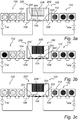
- the light converting device 200 is the one illustrated in Fig. 2a .
- the configuration depicted in Fig. 3a is, for example, intended for use when e.g. the first group of light sources 102 provides a white colour temperature which is slightly warmer than desired.
- the light converting device 200 is connected to the third group of light sources 116. This can be achieved by e.g. pressing, inserting or soldering the light converting device 200 to the third group of light sources.
- the electrical connection means 120 (see Fig. 1 ) of the third group of light sources 116 is electrically connected to the first set 204 of internal electrical wiring, which in turn are electrically connected to the electrical drive current I CW of the first group of light sources 102.
- the electrical drive current I CW of the first group of light sources 102 is supplied to the first 102 and the third 116 groups of light sources.
- the second set 205 of internal electrical wiring closes the electrical circuit of the second group of light sources 110.
- the light converting device 200 as illustrated in the configuration of Fig. 3a may thus compensate, in conjunction with the third group of light sources 116, for the slightly warmer colour temperature by providing a slightly colder colour temperature. Accordingly, in this case the phosphor 208 of the light converting device 200 is selected such that the third colour temperature is colder (i.e. higher Kelvin) than the first colour temperature.
- the illustrated light converting device 200 is the one depicted in Fig. 2b .
- the configuration depicted in Fig. 3b is, for example, intended for use when e.g. the second group of light sources 110 provides a white colour temperature which is slightly colder than desired.
- the light converting device 200 is connected to the third group of light sources in the same manner as described above in relation to Fig. 3a .
- the main difference between the lighting arrangements 100 of Fig. 3a and Fig. 3b is that in Fig.
- the electrical connection means 120 of the third group of light sources 116 is configured such that it is electrically connected to the first set 104' of internal electrical wiring, which in turn is electrically connected to the electrical drive current I WW of the second group of light sources 110.
- the electrical drive current I WW of the second group of light sources 110 is supplied to the second 110 and the third 116 groups of light sources.
- the second set 205' of internal electrical wiring closes the electrical circuit of the first group of light sources 102. Accordingly, if the total white colour temperature of the second group of light sources 110 provides a white colour temperature which is slightly colder than desired, the light converting device 200 as illustrated in the configuration of Fig.
- the 3b may thus compensate, in conjunction with the third group of light sources 116, for the slightly colder colour temperature by providing a slightly warmer colour temperature, i.e. the third group of light sources 116 in conjunction with the second group of light sources 110 provides for an increased amount of warm white light. Accordingly, in this case the phosphor 208' of the light converting device 200 is selected such that the third colour temperature is warmer (i.e. lower Kelvin) than the second colour temperature.
- FIG. 3c Another embodiment of the lighting arrangement is illustrated in Fig. 3c , which comprises the light converting device illustrated in Fig. 2d .
- the configuration depicted in Fig. 3c is, for example, intended for use when e.g. the first group of light sources 110 provides a white colour temperature which is slightly colder than desired.
- the electrical connection means 120 of the third group of light sources 116 is electrically connected to the first set 204 of internal electrical wiring, which in turn is electrically connected to the electrical drive current I CW of the first group of light sources 102.
- the electrical drive current I CW of the first group of light sources 102 is supplied to the first 102 and the third 116 groups of light sources.
- the second set 205 of internal electrical wiring closes the electrical circuit of the second group of light sources 110. Accordingly, if the white colour temperature of the first group of light sources 102 provides a white colour temperature which is slightly colder than desired, the light converting device 200 as illustrated in the configuration of Fig. 3c may thus compensate, in conjunction with the appropriate selection of phosphor 208'" of the third group of light sources 116, for the slightly colder colour temperature by providing a slightly warmer colour temperature.
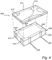
- the light converting device 400 comprises LED package 402 comprising the above described third group of light sources, or being one of the LEDs from the third group of light sources.
- the LED package is provided with contacts for the electrical drive channels 404, 406, 408, where the first drive channel 404 is electrically connected to the first group of light sources, the second drive channel 406 is electrically connected to the second group of light sources, and the third drive channel is electrically connected to a fourth group of light sources.
- the fourth group of light source comprises at least one LED arranged to provide white light having a fourth colour temperature.
- the light converting device 400 may hence be electrically connected to more light sources than the above described light converting device depicted in relation to e.g. Figs. 3a - 3c .
- the third group of light sources is electrically connected via an electrical input interface 410, such as e.g. an electrical terminal to an electrical power source (not shown here) for supplying power to the LED package 402.
- the LED package 402 is further connected to the first group of light sources via internal electrical wiring 412 arranged in a phosphor cap 414 provided onto the LED package 402 and via the first drive channel 404.
- the second 406 and third 408 electrical drive channels closes the electrical circuits of the second and fourth group of light sources, respectively.
- the light converting device 400 as illustrated in Fig. 4 may contribute to the total light outputted from the lighting arrangement by connecting the electrical input interface 410 to the first drive channel 404, i.e. to the first group of light source, via the internal electrical wiring 412 arranged in the phosphor cap 414.
- the internal electrical wiring 412 may of course also be connected to one of the second or fourth group of light sources, via the respective second 416 or third 408 drive channels, instead of the above described first group of light sources.
- the internal electrical wiring 412 may be positioned to other locations than the depicted phosphor cap 414 in Fig. 4 such that the internal electrical wiring 412 provides less impact to the emitted light from the LED package 402.
- An advantage of the embodiment depicted in Fig. 4 is, at least, that the size of the light converting device can be reduced, since the internal electrical wiring 412 is provided within the phosphor cap 414.
- Other advantages are similar to those described above in relation to e.g. Figs 3 a - 3c.
- the above described exemplary embodiments of the lighting arrangement may also be provided with coding criteria.
- the light converting device may be configured with electrical connecting elements which may controllably and electrically connect the light converting device to either one of the first, second or, for the example embodiment depicted in Fig. 4 , the fourth group of light sources. This may be achieved by e.g. providing a shape and position of the electrical connecting means 206 of the third group of light sources 116, such that the orientation of the light converting device 200 selects which one of the first, second or fourth group of light sources will be in electrical connection with the third group of light sources.
- Fig. 4 Although the embodiment depicted in Fig. 4 is illustrated for connection to three groups of light sources by means of the first 404, the second 406 and the third 408 drive channels, the skilled addressee naturally realize that the light converting device 400 may just as well be utilized for e.g. the lighting arrangement 100 depicted in Fig. 1 .
- the light converting device may be connected to even further group of light sources, i.e. the above described example embodiment having a first, a second and a fourth group of light sources connected to the light converting device should not be construed as limiting the scope of the present invention.
- the word "comprising” does not exclude other elements or steps, and the indefinite article "a” or “an” does not exclude a plurality.
Landscapes
- Engineering & Computer Science (AREA)
- General Engineering & Computer Science (AREA)
- Physics & Mathematics (AREA)
- Microelectronics & Electronic Packaging (AREA)
- Optics & Photonics (AREA)
- Spectroscopy & Molecular Physics (AREA)
- Led Device Packages (AREA)
- Circuit Arrangement For Electric Light Sources In General (AREA)
- Non-Portable Lighting Devices Or Systems Thereof (AREA)
- Securing Globes, Refractors, Reflectors Or The Like (AREA)
- Arrangement Of Elements, Cooling, Sealing, Or The Like Of Lighting Devices (AREA)
Applications Claiming Priority (2)
| Application Number | Priority Date | Filing Date | Title |
|---|---|---|---|
| US201261605245P | 2012-03-01 | 2012-03-01 | |
| PCT/IB2013/051500 WO2013128358A1 (en) | 2012-03-01 | 2013-02-25 | Led lighting arrangement |
Publications (2)
| Publication Number | Publication Date |
|---|---|
| EP2820351A1 EP2820351A1 (en) | 2015-01-07 |
| EP2820351B1 true EP2820351B1 (en) | 2017-02-01 |
Family
ID=48182955
Family Applications (1)
| Application Number | Title | Priority Date | Filing Date |
|---|---|---|---|
| EP13718385.1A Not-in-force EP2820351B1 (en) | 2012-03-01 | 2013-02-25 | Led lighting arrangement |
Country Status (5)
| Country | Link |
|---|---|
| US (1) | US9541242B2 (enExample) |
| EP (1) | EP2820351B1 (enExample) |
| JP (1) | JP6178806B2 (enExample) |
| CN (1) | CN104160212B (enExample) |
| WO (1) | WO2013128358A1 (enExample) |
Families Citing this family (2)
| Publication number | Priority date | Publication date | Assignee | Title |
|---|---|---|---|---|
| KR102613239B1 (ko) * | 2018-06-04 | 2023-12-14 | 삼성전자주식회사 | 백색 led 모듈 및 조명 장치 |
| JP7174266B2 (ja) * | 2020-06-30 | 2022-11-17 | 日亜化学工業株式会社 | 発光装置 |
Family Cites Families (22)
| Publication number | Priority date | Publication date | Assignee | Title |
|---|---|---|---|---|
| JP3378465B2 (ja) * | 1997-05-16 | 2003-02-17 | 株式会社東芝 | 発光装置 |
| US20030133292A1 (en) * | 1999-11-18 | 2003-07-17 | Mueller George G. | Methods and apparatus for generating and modulating white light illumination conditions |
| DE19952932C1 (de) * | 1999-11-03 | 2001-05-03 | Osram Opto Semiconductors Gmbh | LED-Weißlichtquelle mit breitbandiger Anregung |
| US7059927B2 (en) | 2002-08-19 | 2006-06-13 | Lite On Technology Corporation | Method for manufacturing white light source |
| CN100352069C (zh) * | 2002-11-25 | 2007-11-28 | 松下电器产业株式会社 | Led照明光源 |
| EP2262006A3 (en) * | 2003-02-26 | 2012-03-21 | Cree, Inc. | Composite white light source and method for fabricating |
| US7329024B2 (en) | 2003-09-22 | 2008-02-12 | Permlight Products, Inc. | Lighting apparatus |
| US7922352B2 (en) * | 2005-07-21 | 2011-04-12 | Avago Technologies General Ip (Singapore) Pte. Ltd. | Device and method for emitting output light using multiple light sources with photoluminescent material |
| WO2007023411A1 (en) | 2005-08-24 | 2007-03-01 | Philips Intellectual Property & Standards Gmbh | Light emitting diodes and lasers diodes with color converters |
| EP1964184A2 (en) * | 2005-12-14 | 2008-09-03 | Koninklijke Philips Electronics N.V. | Solid-state light source and method of producing light of a desired color point |
| US20080151143A1 (en) * | 2006-10-19 | 2008-06-26 | Intematix Corporation | Light emitting diode based backlighting for color liquid crystal displays |
| WO2008152552A1 (en) | 2007-06-13 | 2008-12-18 | Philips Intellectual Property & Standards Gmbh | Led lighting device |
| US20090050912A1 (en) * | 2007-08-24 | 2009-02-26 | Foxsemicon Integrated Technology, Inc. | Light emitting diode and outdoor illumination device having the same |
| JP2009176879A (ja) * | 2008-01-23 | 2009-08-06 | Sanyo Electric Co Ltd | 発光装置 |
| US8550657B2 (en) * | 2008-11-07 | 2013-10-08 | Itramas International, Inc. | Methodology of maintaining CCT for white light using LED |
| JP5178475B2 (ja) * | 2008-11-25 | 2013-04-10 | シャープ株式会社 | 照明装置 |
| TW201040433A (en) * | 2009-05-14 | 2010-11-16 | Young Lighting Technology Corp | Illumination apparatus |
| US9631782B2 (en) | 2010-02-04 | 2017-04-25 | Xicato, Inc. | LED-based rectangular illumination device |
| JP5879739B2 (ja) * | 2010-04-28 | 2016-03-08 | 三菱化学株式会社 | 半導体発光装置用パッケージ及び発光装置 |
| CN102128396B (zh) * | 2011-03-19 | 2013-01-02 | 深圳市尚荣医疗股份有限公司 | 多透镜的led手术无影灯及色温调节的方法 |
| US20130075769A1 (en) * | 2011-09-22 | 2013-03-28 | Ledengin, Inc. | Selection of phosphors and leds in a multi-chip emitter for a single white color bin |
| US9897284B2 (en) * | 2012-03-28 | 2018-02-20 | Ledengin, Inc. | LED-based MR16 replacement lamp |
-
2013
- 2013-02-25 US US14/379,760 patent/US9541242B2/en active Active
- 2013-02-25 EP EP13718385.1A patent/EP2820351B1/en not_active Not-in-force
- 2013-02-25 CN CN201380011942.3A patent/CN104160212B/zh not_active Expired - Fee Related
- 2013-02-25 JP JP2014559330A patent/JP6178806B2/ja not_active Expired - Fee Related
- 2013-02-25 WO PCT/IB2013/051500 patent/WO2013128358A1/en not_active Ceased
Also Published As
| Publication number | Publication date |
|---|---|
| CN104160212A (zh) | 2014-11-19 |
| CN104160212B (zh) | 2018-10-12 |
| EP2820351A1 (en) | 2015-01-07 |
| JP6178806B2 (ja) | 2017-08-09 |
| JP2015515085A (ja) | 2015-05-21 |
| WO2013128358A1 (en) | 2013-09-06 |
| US9541242B2 (en) | 2017-01-10 |
| US20160018067A1 (en) | 2016-01-21 |
Similar Documents
| Publication | Publication Date | Title |
|---|---|---|
| US9232602B2 (en) | Color temperature adjustment for LED lamps using switches | |
| US10098197B2 (en) | Lighting devices with individually compensating multi-color clusters | |
| US8358089B2 (en) | Solid-state lighting of a white light with tunable color temperatures | |
| US8497629B2 (en) | Color-temperature-tunable device | |
| US8901829B2 (en) | Solid state lighting apparatus with configurable shunts | |
| US20140168965A1 (en) | Led device having adjustable color temperature | |
| CN102797999B (zh) | 可变颜色光发射装置及使用该装置的照明设备 | |
| WO1999057945A1 (en) | A lamp employing a monolithic led device | |
| US9080729B2 (en) | Multiple-LED emitter for A-19 lamps | |
| WO2006001221A1 (en) | Illumination source | |
| CN105428344A (zh) | 使用波长转换元件的可调白点光源 | |
| JP2011154910A (ja) | 車両用灯具の半導体型光源の駆動回路、車両用灯具 | |
| US20200146119A1 (en) | Wirelessly Controllable Lighting Modules | |
| US20200053852A1 (en) | Light emitting device | |
| EP2820351B1 (en) | Led lighting arrangement | |
| US9599294B2 (en) | LED lighting device with mint, amber and yellow colored light-emitting diodes | |
| US11363687B2 (en) | Low voltage switching device | |
| US20200245426A1 (en) | Light apparatus | |
| KR20220094290A (ko) | 백색 발광장치 및 조명 장치 | |
| JP2014194858A (ja) | Led照明装置 |
Legal Events
| Date | Code | Title | Description |
|---|---|---|---|
| PUAI | Public reference made under article 153(3) epc to a published international application that has entered the european phase |
Free format text: ORIGINAL CODE: 0009012 |
|
| 17P | Request for examination filed |
Effective date: 20141001 |
|
| AK | Designated contracting states |
Kind code of ref document: A1 Designated state(s): AL AT BE BG CH CY CZ DE DK EE ES FI FR GB GR HR HU IE IS IT LI LT LU LV MC MK MT NL NO PL PT RO RS SE SI SK SM TR |
|
| AX | Request for extension of the european patent |
Extension state: BA ME |
|
| DAX | Request for extension of the european patent (deleted) | ||
| 17Q | First examination report despatched |
Effective date: 20150918 |
|
| REG | Reference to a national code |
Ref country code: DE Ref legal event code: R079 Ref document number: 602013017003 Country of ref document: DE Free format text: PREVIOUS MAIN CLASS: F21V0017000000 Ipc: F21V0017040000 |
|
| RIC1 | Information provided on ipc code assigned before grant |
Ipc: F21Y 115/10 20160101ALI20160114BHEP Ipc: F21V 23/06 20060101ALI20160114BHEP Ipc: F21V 17/04 20060101AFI20160114BHEP Ipc: F21V 9/16 20060101ALI20160114BHEP Ipc: F21V 17/10 20060101ALI20160114BHEP |
|
| GRAP | Despatch of communication of intention to grant a patent |
Free format text: ORIGINAL CODE: EPIDOSNIGR1 |
|
| INTG | Intention to grant announced |
Effective date: 20160223 |
|
| RAP1 | Party data changed (applicant data changed or rights of an application transferred) |
Owner name: PHILIPS GMBH Owner name: KONINKLIJKE PHILIPS N.V. |
|
| GRAS | Grant fee paid |
Free format text: ORIGINAL CODE: EPIDOSNIGR3 |
|
| RAP1 | Party data changed (applicant data changed or rights of an application transferred) |
Owner name: PHILIPS LIGHTING HOLDING B.V. |
|
| GRAA | (expected) grant |
Free format text: ORIGINAL CODE: 0009210 |
|
| AK | Designated contracting states |
Kind code of ref document: B1 Designated state(s): AL AT BE BG CH CY CZ DE DK EE ES FI FR GB GR HR HU IE IS IT LI LT LU LV MC MK MT NL NO PL PT RO RS SE SI SK SM TR |
|
| REG | Reference to a national code |
Ref country code: GB Ref legal event code: FG4D |
|
| REG | Reference to a national code |
Ref country code: CH Ref legal event code: EP Ref country code: AT Ref legal event code: REF Ref document number: 865908 Country of ref document: AT Kind code of ref document: T Effective date: 20170215 |
|
| REG | Reference to a national code |
Ref country code: IE Ref legal event code: FG4D |
|
| REG | Reference to a national code |
Ref country code: FR Ref legal event code: PLFP Year of fee payment: 5 |
|
| REG | Reference to a national code |
Ref country code: DE Ref legal event code: R096 Ref document number: 602013017003 Country of ref document: DE |
|
| REG | Reference to a national code |
Ref country code: NL Ref legal event code: MP Effective date: 20170201 |
|
| REG | Reference to a national code |
Ref country code: LT Ref legal event code: MG4D |
|
| REG | Reference to a national code |
Ref country code: AT Ref legal event code: MK05 Ref document number: 865908 Country of ref document: AT Kind code of ref document: T Effective date: 20170201 |
|
| PG25 | Lapsed in a contracting state [announced via postgrant information from national office to epo] |
Ref country code: HR Free format text: LAPSE BECAUSE OF FAILURE TO SUBMIT A TRANSLATION OF THE DESCRIPTION OR TO PAY THE FEE WITHIN THE PRESCRIBED TIME-LIMIT Effective date: 20170201 Ref country code: LT Free format text: LAPSE BECAUSE OF FAILURE TO SUBMIT A TRANSLATION OF THE DESCRIPTION OR TO PAY THE FEE WITHIN THE PRESCRIBED TIME-LIMIT Effective date: 20170201 Ref country code: NO Free format text: LAPSE BECAUSE OF FAILURE TO SUBMIT A TRANSLATION OF THE DESCRIPTION OR TO PAY THE FEE WITHIN THE PRESCRIBED TIME-LIMIT Effective date: 20170501 Ref country code: IS Free format text: LAPSE BECAUSE OF FAILURE TO SUBMIT A TRANSLATION OF THE DESCRIPTION OR TO PAY THE FEE WITHIN THE PRESCRIBED TIME-LIMIT Effective date: 20170601 Ref country code: FI Free format text: LAPSE BECAUSE OF FAILURE TO SUBMIT A TRANSLATION OF THE DESCRIPTION OR TO PAY THE FEE WITHIN THE PRESCRIBED TIME-LIMIT Effective date: 20170201 Ref country code: GR Free format text: LAPSE BECAUSE OF FAILURE TO SUBMIT A TRANSLATION OF THE DESCRIPTION OR TO PAY THE FEE WITHIN THE PRESCRIBED TIME-LIMIT Effective date: 20170502 |
|
| RIN2 | Information on inventor provided after grant (corrected) |
Inventor name: RADERMACHER, HARALD, JOSEF, GUENTHER |
|
| PG25 | Lapsed in a contracting state [announced via postgrant information from national office to epo] |
Ref country code: RS Free format text: LAPSE BECAUSE OF FAILURE TO SUBMIT A TRANSLATION OF THE DESCRIPTION OR TO PAY THE FEE WITHIN THE PRESCRIBED TIME-LIMIT Effective date: 20170201 Ref country code: PT Free format text: LAPSE BECAUSE OF FAILURE TO SUBMIT A TRANSLATION OF THE DESCRIPTION OR TO PAY THE FEE WITHIN THE PRESCRIBED TIME-LIMIT Effective date: 20170601 Ref country code: PL Free format text: LAPSE BECAUSE OF FAILURE TO SUBMIT A TRANSLATION OF THE DESCRIPTION OR TO PAY THE FEE WITHIN THE PRESCRIBED TIME-LIMIT Effective date: 20170201 Ref country code: SE Free format text: LAPSE BECAUSE OF FAILURE TO SUBMIT A TRANSLATION OF THE DESCRIPTION OR TO PAY THE FEE WITHIN THE PRESCRIBED TIME-LIMIT Effective date: 20170201 Ref country code: AT Free format text: LAPSE BECAUSE OF FAILURE TO SUBMIT A TRANSLATION OF THE DESCRIPTION OR TO PAY THE FEE WITHIN THE PRESCRIBED TIME-LIMIT Effective date: 20170201 Ref country code: BG Free format text: LAPSE BECAUSE OF FAILURE TO SUBMIT A TRANSLATION OF THE DESCRIPTION OR TO PAY THE FEE WITHIN THE PRESCRIBED TIME-LIMIT Effective date: 20170501 Ref country code: ES Free format text: LAPSE BECAUSE OF FAILURE TO SUBMIT A TRANSLATION OF THE DESCRIPTION OR TO PAY THE FEE WITHIN THE PRESCRIBED TIME-LIMIT Effective date: 20170201 Ref country code: NL Free format text: LAPSE BECAUSE OF FAILURE TO SUBMIT A TRANSLATION OF THE DESCRIPTION OR TO PAY THE FEE WITHIN THE PRESCRIBED TIME-LIMIT Effective date: 20170201 Ref country code: LV Free format text: LAPSE BECAUSE OF FAILURE TO SUBMIT A TRANSLATION OF THE DESCRIPTION OR TO PAY THE FEE WITHIN THE PRESCRIBED TIME-LIMIT Effective date: 20170201 |
|
| REG | Reference to a national code |
Ref country code: CH Ref legal event code: PL |
|
| PG25 | Lapsed in a contracting state [announced via postgrant information from national office to epo] |
Ref country code: IT Free format text: LAPSE BECAUSE OF FAILURE TO SUBMIT A TRANSLATION OF THE DESCRIPTION OR TO PAY THE FEE WITHIN THE PRESCRIBED TIME-LIMIT Effective date: 20170201 Ref country code: LI Free format text: LAPSE BECAUSE OF NON-PAYMENT OF DUE FEES Effective date: 20170228 Ref country code: CZ Free format text: LAPSE BECAUSE OF FAILURE TO SUBMIT A TRANSLATION OF THE DESCRIPTION OR TO PAY THE FEE WITHIN THE PRESCRIBED TIME-LIMIT Effective date: 20170201 Ref country code: SK Free format text: LAPSE BECAUSE OF FAILURE TO SUBMIT A TRANSLATION OF THE DESCRIPTION OR TO PAY THE FEE WITHIN THE PRESCRIBED TIME-LIMIT Effective date: 20170201 Ref country code: RO Free format text: LAPSE BECAUSE OF FAILURE TO SUBMIT A TRANSLATION OF THE DESCRIPTION OR TO PAY THE FEE WITHIN THE PRESCRIBED TIME-LIMIT Effective date: 20170201 Ref country code: EE Free format text: LAPSE BECAUSE OF FAILURE TO SUBMIT A TRANSLATION OF THE DESCRIPTION OR TO PAY THE FEE WITHIN THE PRESCRIBED TIME-LIMIT Effective date: 20170201 Ref country code: CH Free format text: LAPSE BECAUSE OF NON-PAYMENT OF DUE FEES Effective date: 20170228 |
|
| REG | Reference to a national code |
Ref country code: DE Ref legal event code: R097 Ref document number: 602013017003 Country of ref document: DE |
|
| REG | Reference to a national code |
Ref country code: IE Ref legal event code: MM4A |
|
| PG25 | Lapsed in a contracting state [announced via postgrant information from national office to epo] |
Ref country code: SM Free format text: LAPSE BECAUSE OF FAILURE TO SUBMIT A TRANSLATION OF THE DESCRIPTION OR TO PAY THE FEE WITHIN THE PRESCRIBED TIME-LIMIT Effective date: 20170201 Ref country code: DK Free format text: LAPSE BECAUSE OF FAILURE TO SUBMIT A TRANSLATION OF THE DESCRIPTION OR TO PAY THE FEE WITHIN THE PRESCRIBED TIME-LIMIT Effective date: 20170201 Ref country code: MC Free format text: LAPSE BECAUSE OF FAILURE TO SUBMIT A TRANSLATION OF THE DESCRIPTION OR TO PAY THE FEE WITHIN THE PRESCRIBED TIME-LIMIT Effective date: 20170201 |
|
| PLBE | No opposition filed within time limit |
Free format text: ORIGINAL CODE: 0009261 |
|
| STAA | Information on the status of an ep patent application or granted ep patent |
Free format text: STATUS: NO OPPOSITION FILED WITHIN TIME LIMIT |
|
| PG25 | Lapsed in a contracting state [announced via postgrant information from national office to epo] |
Ref country code: LU Free format text: LAPSE BECAUSE OF NON-PAYMENT OF DUE FEES Effective date: 20170225 |
|
| 26N | No opposition filed |
Effective date: 20171103 |
|
| REG | Reference to a national code |
Ref country code: BE Ref legal event code: MM Effective date: 20170228 |
|
| REG | Reference to a national code |
Ref country code: FR Ref legal event code: PLFP Year of fee payment: 6 |
|
| PG25 | Lapsed in a contracting state [announced via postgrant information from national office to epo] |
Ref country code: IE Free format text: LAPSE BECAUSE OF NON-PAYMENT OF DUE FEES Effective date: 20170225 Ref country code: SI Free format text: LAPSE BECAUSE OF FAILURE TO SUBMIT A TRANSLATION OF THE DESCRIPTION OR TO PAY THE FEE WITHIN THE PRESCRIBED TIME-LIMIT Effective date: 20170201 |
|
| PG25 | Lapsed in a contracting state [announced via postgrant information from national office to epo] |
Ref country code: BE Free format text: LAPSE BECAUSE OF NON-PAYMENT OF DUE FEES Effective date: 20170228 |
|
| PG25 | Lapsed in a contracting state [announced via postgrant information from national office to epo] |
Ref country code: MT Free format text: LAPSE BECAUSE OF NON-PAYMENT OF DUE FEES Effective date: 20170225 |
|
| PG25 | Lapsed in a contracting state [announced via postgrant information from national office to epo] |
Ref country code: HU Free format text: LAPSE BECAUSE OF FAILURE TO SUBMIT A TRANSLATION OF THE DESCRIPTION OR TO PAY THE FEE WITHIN THE PRESCRIBED TIME-LIMIT; INVALID AB INITIO Effective date: 20130225 |
|
| PG25 | Lapsed in a contracting state [announced via postgrant information from national office to epo] |
Ref country code: CY Free format text: LAPSE BECAUSE OF FAILURE TO SUBMIT A TRANSLATION OF THE DESCRIPTION OR TO PAY THE FEE WITHIN THE PRESCRIBED TIME-LIMIT Effective date: 20170201 |
|
| PG25 | Lapsed in a contracting state [announced via postgrant information from national office to epo] |
Ref country code: MK Free format text: LAPSE BECAUSE OF FAILURE TO SUBMIT A TRANSLATION OF THE DESCRIPTION OR TO PAY THE FEE WITHIN THE PRESCRIBED TIME-LIMIT Effective date: 20170201 |
|
| PG25 | Lapsed in a contracting state [announced via postgrant information from national office to epo] |
Ref country code: TR Free format text: LAPSE BECAUSE OF FAILURE TO SUBMIT A TRANSLATION OF THE DESCRIPTION OR TO PAY THE FEE WITHIN THE PRESCRIBED TIME-LIMIT Effective date: 20170201 |
|
| PG25 | Lapsed in a contracting state [announced via postgrant information from national office to epo] |
Ref country code: AL Free format text: LAPSE BECAUSE OF FAILURE TO SUBMIT A TRANSLATION OF THE DESCRIPTION OR TO PAY THE FEE WITHIN THE PRESCRIBED TIME-LIMIT Effective date: 20170201 |
|
| REG | Reference to a national code |
Ref country code: DE Ref legal event code: R082 Ref document number: 602013017003 Country of ref document: DE Representative=s name: MEISSNER BOLTE PATENTANWAELTE RECHTSANWAELTE P, DE Ref country code: DE Ref legal event code: R081 Ref document number: 602013017003 Country of ref document: DE Owner name: SIGNIFY HOLDING B.V., NL Free format text: FORMER OWNER: PHILIPS LIGHTING HOLDING B.V., EINDHOVEN, NL |
|
| P01 | Opt-out of the competence of the unified patent court (upc) registered |
Effective date: 20230421 |
|
| PGFP | Annual fee paid to national office [announced via postgrant information from national office to epo] |
Ref country code: GB Payment date: 20240220 Year of fee payment: 12 |
|
| PGFP | Annual fee paid to national office [announced via postgrant information from national office to epo] |
Ref country code: FR Payment date: 20240226 Year of fee payment: 12 |
|
| PGFP | Annual fee paid to national office [announced via postgrant information from national office to epo] |
Ref country code: DE Payment date: 20240429 Year of fee payment: 12 |
|
| REG | Reference to a national code |
Ref country code: DE Ref legal event code: R119 Ref document number: 602013017003 Country of ref document: DE |
|
| GBPC | Gb: european patent ceased through non-payment of renewal fee |
Effective date: 20250225 |
|
| PG25 | Lapsed in a contracting state [announced via postgrant information from national office to epo] |
Ref country code: DE Free format text: LAPSE BECAUSE OF NON-PAYMENT OF DUE FEES Effective date: 20250902 |
|
| PG25 | Lapsed in a contracting state [announced via postgrant information from national office to epo] |
Ref country code: GB Free format text: LAPSE BECAUSE OF NON-PAYMENT OF DUE FEES Effective date: 20250225 |
|
| PG25 | Lapsed in a contracting state [announced via postgrant information from national office to epo] |
Ref country code: FR Free format text: LAPSE BECAUSE OF NON-PAYMENT OF DUE FEES Effective date: 20250228 |