EP2819836B1 - Apparatus for casting a non-pneumatic tire having a floating mold alignment mechanism - Google Patents
Apparatus for casting a non-pneumatic tire having a floating mold alignment mechanism Download PDFInfo
- Publication number
- EP2819836B1 EP2819836B1 EP12870298.2A EP12870298A EP2819836B1 EP 2819836 B1 EP2819836 B1 EP 2819836B1 EP 12870298 A EP12870298 A EP 12870298A EP 2819836 B1 EP2819836 B1 EP 2819836B1
- Authority
- EP
- European Patent Office
- Prior art keywords
- mold
- platen
- slide
- molding press
- alignment mechanism
- Prior art date
- Legal status (The legal status is an assumption and is not a legal conclusion. Google has not performed a legal analysis and makes no representation as to the accuracy of the status listed.)
- Not-in-force
Links
- 230000007246 mechanism Effects 0.000 title claims description 50
- 238000007667 floating Methods 0.000 title claims description 16
- 238000005266 casting Methods 0.000 title description 2
- 238000000465 moulding Methods 0.000 claims description 50
- 230000006835 compression Effects 0.000 claims description 4
- 238000007906 compression Methods 0.000 claims description 4
- 230000013011 mating Effects 0.000 claims description 2
- 229920002635 polyurethane Polymers 0.000 description 10
- 239000004814 polyurethane Substances 0.000 description 10
- 239000000463 material Substances 0.000 description 7
- 238000000034 method Methods 0.000 description 6
- 230000000712 assembly Effects 0.000 description 5
- 238000000429 assembly Methods 0.000 description 5
- 239000007788 liquid Substances 0.000 description 4
- 230000008569 process Effects 0.000 description 4
- 230000008878 coupling Effects 0.000 description 2
- 238000010168 coupling process Methods 0.000 description 2
- 238000005859 coupling reaction Methods 0.000 description 2
- 230000006870 function Effects 0.000 description 2
- 230000002706 hydrostatic effect Effects 0.000 description 2
- 238000004519 manufacturing process Methods 0.000 description 2
- 239000012528 membrane Substances 0.000 description 2
- 230000013707 sensory perception of sound Effects 0.000 description 2
- 229910000906 Bronze Inorganic materials 0.000 description 1
- 229910000831 Steel Inorganic materials 0.000 description 1
- XAGFODPZIPBFFR-UHFFFAOYSA-N aluminium Chemical compound [Al] XAGFODPZIPBFFR-UHFFFAOYSA-N 0.000 description 1
- 229910052782 aluminium Inorganic materials 0.000 description 1
- 230000015572 biosynthetic process Effects 0.000 description 1
- 239000010974 bronze Substances 0.000 description 1
- 238000005119 centrifugation Methods 0.000 description 1
- 238000010276 construction Methods 0.000 description 1
- KUNSUQLRTQLHQQ-UHFFFAOYSA-N copper tin Chemical compound [Cu].[Sn] KUNSUQLRTQLHQQ-UHFFFAOYSA-N 0.000 description 1
- 230000003247 decreasing effect Effects 0.000 description 1
- 230000000694 effects Effects 0.000 description 1
- 229920001971 elastomer Polymers 0.000 description 1
- 230000008030 elimination Effects 0.000 description 1
- 238000003379 elimination reaction Methods 0.000 description 1
- 238000005516 engineering process Methods 0.000 description 1
- 239000012530 fluid Substances 0.000 description 1
- 230000005484 gravity Effects 0.000 description 1
- 229920003023 plastic Polymers 0.000 description 1
- 239000004033 plastic Substances 0.000 description 1
- 239000007787 solid Substances 0.000 description 1
- 239000010959 steel Substances 0.000 description 1
- 229920001187 thermosetting polymer Polymers 0.000 description 1
- 239000002699 waste material Substances 0.000 description 1
Images




Classifications
-
- B—PERFORMING OPERATIONS; TRANSPORTING
- B29—WORKING OF PLASTICS; WORKING OF SUBSTANCES IN A PLASTIC STATE IN GENERAL
- B29D—PRODUCING PARTICULAR ARTICLES FROM PLASTICS OR FROM SUBSTANCES IN A PLASTIC STATE
- B29D30/00—Producing pneumatic or solid tyres or parts thereof
- B29D30/02—Solid tyres ; Moulds therefor
-
- B—PERFORMING OPERATIONS; TRANSPORTING
- B29—WORKING OF PLASTICS; WORKING OF SUBSTANCES IN A PLASTIC STATE IN GENERAL
- B29C—SHAPING OR JOINING OF PLASTICS; SHAPING OF MATERIAL IN A PLASTIC STATE, NOT OTHERWISE PROVIDED FOR; AFTER-TREATMENT OF THE SHAPED PRODUCTS, e.g. REPAIRING
- B29C41/00—Shaping by coating a mould, core or other substrate, i.e. by depositing material and stripping-off the shaped article; Apparatus therefor
- B29C41/02—Shaping by coating a mould, core or other substrate, i.e. by depositing material and stripping-off the shaped article; Apparatus therefor for making articles of definite length, i.e. discrete articles
- B29C41/04—Rotational or centrifugal casting, i.e. coating the inside of a mould by rotating the mould
- B29C41/042—Rotational or centrifugal casting, i.e. coating the inside of a mould by rotating the mould by rotating a mould around its axis of symmetry
-
- B—PERFORMING OPERATIONS; TRANSPORTING
- B29—WORKING OF PLASTICS; WORKING OF SUBSTANCES IN A PLASTIC STATE IN GENERAL
- B29C—SHAPING OR JOINING OF PLASTICS; SHAPING OF MATERIAL IN A PLASTIC STATE, NOT OTHERWISE PROVIDED FOR; AFTER-TREATMENT OF THE SHAPED PRODUCTS, e.g. REPAIRING
- B29C41/00—Shaping by coating a mould, core or other substrate, i.e. by depositing material and stripping-off the shaped article; Apparatus therefor
- B29C41/34—Component parts, details or accessories; Auxiliary operations
- B29C41/38—Moulds, cores or other substrates
-
- B—PERFORMING OPERATIONS; TRANSPORTING
- B29—WORKING OF PLASTICS; WORKING OF SUBSTANCES IN A PLASTIC STATE IN GENERAL
- B29D—PRODUCING PARTICULAR ARTICLES FROM PLASTICS OR FROM SUBSTANCES IN A PLASTIC STATE
- B29D30/00—Producing pneumatic or solid tyres or parts thereof
-
- B—PERFORMING OPERATIONS; TRANSPORTING
- B29—WORKING OF PLASTICS; WORKING OF SUBSTANCES IN A PLASTIC STATE IN GENERAL
- B29D—PRODUCING PARTICULAR ARTICLES FROM PLASTICS OR FROM SUBSTANCES IN A PLASTIC STATE
- B29D30/00—Producing pneumatic or solid tyres or parts thereof
- B29D30/06—Pneumatic tyres or parts thereof (e.g. produced by casting, moulding, compression moulding, injection moulding, centrifugal casting)
- B29D30/0601—Vulcanising tyres; Vulcanising presses for tyres
- B29D30/0605—Vulcanising presses characterised by moulds integral with the presses having radially movable sectors
-
- B—PERFORMING OPERATIONS; TRANSPORTING
- B29—WORKING OF PLASTICS; WORKING OF SUBSTANCES IN A PLASTIC STATE IN GENERAL
- B29C—SHAPING OR JOINING OF PLASTICS; SHAPING OF MATERIAL IN A PLASTIC STATE, NOT OTHERWISE PROVIDED FOR; AFTER-TREATMENT OF THE SHAPED PRODUCTS, e.g. REPAIRING
- B29C33/00—Moulds or cores; Details thereof or accessories therefor
- B29C33/30—Mounting, exchanging or centering
- B29C33/303—Mounting, exchanging or centering centering mould parts or halves, e.g. during mounting
-
- B—PERFORMING OPERATIONS; TRANSPORTING
- B29—WORKING OF PLASTICS; WORKING OF SUBSTANCES IN A PLASTIC STATE IN GENERAL
- B29D—PRODUCING PARTICULAR ARTICLES FROM PLASTICS OR FROM SUBSTANCES IN A PLASTIC STATE
- B29D30/00—Producing pneumatic or solid tyres or parts thereof
- B29D30/06—Pneumatic tyres or parts thereof (e.g. produced by casting, moulding, compression moulding, injection moulding, centrifugal casting)
- B29D30/0601—Vulcanising tyres; Vulcanising presses for tyres
Definitions
- This invention relates generally to an apparatus for rotationally casting a portion of a tire, as for example described in CA 1 293 602 C or US 5 906 836 A , and, more specifically, to an apparatus that has a floating alignment mechanism that allows a portion of a mold to move in the radial direction of the tire, which it at least partially forms, allowing the molding apparatus to omit the use of tie bars.
- the non-pneumatic tire includes an outer annular shear band and a plurality of web spokes that extend transversely across and radially inward from the annular shear band and are anchored in a wheel or hub.
- the annular shear band may further comprise a shear layer, at least a first membrane adhered to the radially inward extent of the shear layer and at least a second membrane adhered to the radially outward extent of the shear layer.
- FIG, 1 shows such a tire that defines a radial direction R.
- the tire 100 comprises a tread 102 that is attached to the outward extent 104 of the spokes 106, which in turn, are connected to a hub or wheel 108 at their inward extent 110 by means known in the art such as by molding spokes between the hub 108 and the tread 102 , which have been prepared for suitable bonding to the polyurethane.
- An outer annular band 105 is located between the outward extent of the spokes and the tread and an inner annular band 107 is found at the inward extent of the spokes, connecting them together.
- This inner annular band 107 can be used to attach the tire to a hub or wheel.
- the annular bands 105 , 107 and spokes 106 are formed by pouring a polyurethane liquid into a rotational mold where the liquid is spread via centrifugation and then cured or hardened, It can also be seen that the spokes 106 are grouped in pairs and that the individual spokes 106' , 106" within each pair are consistently spaced from each other and that each pair is spaced consistently front the adjacent pair around the circumference of the tire. The spacing within each pair and the spacing between each adjacent pair do not need to be the same. As described by the Abstract and col. 2, lines 28 - 41 of the '194 patent, the spokes 106 suppon the tire 100 in tension near the top of the tire 100 and not in compression. Instead, the spokes 106 at the bottom of the tire near the contact patch, which is where the tread 102 of the tire 100 contacts the road, compress or buckle easily. This helps the tire to simulate the pneumatic support function of a pneumatic tire.
- annular bands 105. 107 serve, i.e. to create the bond between the tread and the hub or wheel, as well as aesthetic concerns, it is desirable that the thickness of the bands remain constant.
- mold cores 238" found on a bottom mold half 234 are shown that form the spokes and inside surfaces 101 of the annular bands. These mold cores arc drafted on the surfaces 237 that form the spokes themselves as mold cores coming from one side of the mold interarticulate with similarly configured mold cores coming from the other half (as better described later) so that the thickness of the spokes can remain constant even if there is draft present. However, these mold cores are undrafted on the surfaces 235 that form the inside surfaces of the annular bands.
- the inside surface of the outer annular band 105 is substantially cylindrical, requiring that the inside surface of the outer annular band also be cylindrical to maintain the thickness of the annular band and to avoid aesthetic inconsistencies on the outer annular band from one side of the tire to the other. A similar situation exists for the inside annular band.
- the depth of the mold cores is equal to or greater than 150 mm, which is a deeper draw than is typical. This added to the fact there are surfaces lacking draft means that the spokes are proned to stick often when demolding. This can cause distortion of the spokes and annular bands and/or undesirable and non-uniform appearance. Any misalignment of the mold halves in the radial direction further exacerbates this problem. Therefore, this problem could be helped if a high degree of mold alignment were present to make sure that movement of mold halves and their associated mold cores was purely translational as mold opening and demolding occurred. This could be facilitated by the use of traditional tie bars that connect the mold platens and guide their movement.
- the molding press and associated platens are designed to open rotationally, about the vertical and horizontal axes, as well as translate for opening and closing the mold.
- This wide range of movement in addition to the desire to have free access to the interior of the mold for accessing its components as well as a tire being made therein make the use of such tie bars impractical.
- the lack of tie bars means that mold platens and mold halves may be misaligned, which during demolding, can cause distortion of the spokes of the tire.
- an apparatus for molding a tire having a radial direction that includes a molding press and a mold.
- the molding press may have first and second platens that are operatively associated with the press for changing their position relative to each other for opening and closing a mold that is attached to the platens.
- the mold may have first and second portions that are attached to the first and second platens of the molding press respectively.
- the apparatus may further include a floating mold alignment mechanism that is operatively associated with the first portion of the mold, the first platen and the molding press, said mechanism including at least one sliding member that allows the first portion of the mold to freely move in said radial direction a predetermined amount.
- the motor may drive the second portion of the mold and the cap and outer ring of the first portion of the mold may be coupled to the second portion of the mold when the mold is closed, causing the first portion of the mold to rotate.
- the first mold portion is a mold half.
- the first portion of the mold is fixedly attached to the first platen and said press has a frame and said mold alignment mechanism is slidably attached to the frame and is also slidably attached to the first platen.
- the mold alignment mechanism comprises a first slide and a second slide that are operatively associated with the first platen, first mold portion and molding press, said slides being arranged for orthogonal movement relative to each other.
- the mold alignment mechanism further comprises a set of needle bearings that guide the movement of one slide and another set of needle bearings that guide the movement of the other slide.
- the first and second slides may be similarly configured with v-shaped protrusions on two lateral sides.
- the mold alignment mechanism may further comprise four v-shaped races with sets of needle bearings found on opposing sides of the races that mate with the v-shaped protrusions of the slide, two of said v-shaped races mating with each of the slides, providing four sets of needle bearings for guiding each slide.
- the apparatus may further comprise two gibs for each slide for guiding the movement of each slide wherein the gibs have v-shaped grooves for retaining the v-shaped protrusions of the slides.
- the predetermined amount of radial movement may be at least .5 mm and could range from 1 to 2.5 mm.
- the molding press may be a vertical molding press and the first platen may be an upper platen and the second platen is a lower platen.
- the upper platen may include an opening that serves as a pouring slot when the mold is closed.
- the upper platen may be pivotally connected to the molding press and the lower platen may be translatably connected to the molding press in a vertical direction.
- the apparatus may further include a freeplay adjusting mechanism that limits the movement of the floating mold alignment mechanism in at least one direction.
- This freeplay adjusting mechanism may comprise an attachment member having an aperture and a stud.
- the stud may have threaded ends and a flange, one of the threaded ends may be configured to mate with a threaded hole found on the slide.
- the stud may be further configured so that the flange is found adjacent the slide and the attachment member, which is to say between them, after the stud has been secured to the slide and passed through the aperture of the attachment member.
- This mechanism may further comprise a nut that is attached to the free threaded end of the stud that extends past the attachment member.
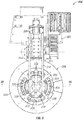
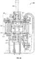
- this apparatus 200 includes a vertical molding press 202 comprising a lower platen 204, upper platen 206 , hydraulic cylinder 208 , arm 210, a gear 212 and frame 214 .
- the frame 214 is fixed and the lower platen 204 is translatably fixed in a horizontal plane but is free to translate vertically while the upper platen 206 is pivotally connected to the frame 214 via pin 211.
- the upper platen 206 is moved by the hydraulic cylinder 208 in and out of a parallel alignment with the lower platen 204.
- Both platens can also rotate about a horizontal axis as previously described.
- the gear 212 mates with a drive pinion (not shown) powered by a motor (not shown) that can engage and disengage the gear 212 when it is appropriate to rotate the lower platen 204 and mold 216, which is affixed thereto, to form the spokes 106 as will be explained later.
- the upper platen 206 could be translatably connected to the flame 214 and could be moved by means other than hydraulic, such as pneumatic, mechanical or other means commonly known in the art.
- the rotation of the lower platen 204 could be achieved by way of other means known in the art such as by an electric motor that is directly coupled to the shaft 218 to which the lower platen 204 is attached.
- the translation of the lower platen can be achieved using the same methods mentioned previously for moving the upper platen 206 .
- Roller bearings 220 are also provided to guide the rotation of the lower platen 204 and to minimize the friction associated with its rotation.
- a floating mold alignment (not shown in FIGS. 3 thru 3C ) mechanism attaches the top platen to the arm of the mold frame but it is contemplated that this alignment mechanism could be interposed between the upper mold half 236 and the upper mold platen 206. Details of this alignment mechanism are further described later.
- the top view provided by FIG. 3 depicts how the upper platen 206 is attached to the frame 214 using the arm 210 in an effective manner requiring as little material as possible.
- the upper platen 206 has a generally thin cylindrical shape that is split into a central portion 222 and an outer annular portion 224 .
- the arm 210 of the molding press 202 extends horizontally from the frame 214 and down a small distance vertically to connect to the central portion 222 of the top platen 206 .
- Five slender connecting members 226, arranged in a circular array, extend from the central portion 222 and connect to the outer annular portion 224.
- the inner and outer portions 222, 224 of the top platen 206 are configured concentrically with five openings 228 found between them and the connecting members, one of which is above the pouring slot 230.
- top platen and its attachment to the frame of the molding press could be achieved in other ways.
- separate arms could be used to connect the inner and outer portions of the top platen to the frame of the molding press.
- the openings found on top surface of the upper platen could be replaced by a single aperture that extends through the side surface of the mold platen or through a side surface of the mold far enough to reach the pouring slot.
- the mold 216 includes a lower portion 234 and an upper portion 236 that each have cores 238 that interarticulate to define the cavities that form the spokes 106 as the cores extend from one side of the mold to the other in an alternating fashion around the circumference of the mold.
- Diametrically opposing cores are shown with core 238' on the left side of the figure extending from the top portion 236 of the mold 216 and core 238" on the right side of the figure extending from the bottom portion 234 of the mold 212 .
- the cores 238 shut off on slightly contoured surfaces 240, but it is contemplated that they could extend into the opposing mold half in a telescoping manner. Other common mold features such as vents here as they are not important to the present invention, but are often used.
- the cores are shown as solid extensions of the mold halves, but they could be separate inserts for ease of replacement should one of them be damaged. Mold alignment features in the form of taper pins 239 are shown in FIG. 2 .
- the tread 102 of the tire 100 is placed in an annular groove 242 found along the circumferential surface of the mold 216 after the mold is opened by pivoting the upper platen 206 up and away from the lower platen 204 and the lower platen is translated downward to a middle position.
- a slight interference (not clearly shown) is provided near the bottom of the annular groove 242 between the tread 102 and cores 238 so that as a robotic arm places a tread into the mold, it can press the tread onto the core causing a small press fit locally, which tends to keep the tread 102 seated during the molding process,
- a clearance groove 244 is also provided along the outside surfaces of the cores 238 in order to allow the flow of polyurethane along the inside surface of the tread 102, facilitating the bonding of the spokes 106 to the tread 102 and forming the outer annular band 105 as previously described.
- the hub 108 is situated in a pocket 246 found in the center of the mold 216 by a robotic arm or other means commonly known in the art and is guided into place by a sleeve 248 having a lead-in surface 250.
- the upper mold portion 236 comprises a rotating cap assembly 252 that is rotatably attached to the mold press 202 and is guided by roller bearings 254.
- the roller bearings 254 used in this case are model numbers 42687/42620 sold by SIMPLY BEARINGS LTD. (SKF).
- SSF SIMPLY BEARINGS LTD.
- other rotatable attachments arc feasible such as a journal bearing or magnetic bearing depending on the application provided they allow this assembly to rotate freely.
- a gap 251 is provided between the press 202 and this assembly 252 to limit the amount of friction created as the assembly rotates.
- This rotating cap assembly 252 includes a shaft 256 that is guided by the bearings and that has a flange 258 attached to its bottom end.
- a cap 260 is connected below the flange 258 by at least one, and sometimes four, bolt and compression spring subassemblies 262.
- the cap 260 has a chamfer 264 located on its bottom edge for properly aligning the cap 260 to the hub 108 as the upper platen of the molding press pivots downward into a parallel alignment with the lower platen and the lower platen translates upward to its top position where the mold is closed. Now, the chamfered portion of the cap 260 extends down past the topmost part of the hub 108 and into its interior as shown by FIG. 3B .
- the upper portion 236 of the mold 216 includes an outer ring assembly 232 that is rotatably attached to the upper platen 206 of the molding press 202 using a large diameter slewing bearing 266 that is found outside of the pouring slot 230 in a radial direction R of the mold (consistent with the coordinate axes of a tire that is contained within the mold).
- a large diameter slewing bearing 266 that is found outside of the pouring slot 230 in a radial direction R of the mold (consistent with the coordinate axes of a tire that is contained within the mold).
- Other rotatable attachments can be used in lieu of the slewing bearing such as a journal bearing or magnetic bearing depending on the application provided that they reduce the amount of resistance to rotation, i.e. friction, a suitable amount.
- materials such as bronze or plastic may be used to create a rotating attachment where these materials that have a low coefficient of friction slide against one another.
- compression springs 268 or alternatively disk springs are provided between the head of the bolt and the bottom surface of the counterhore in which the head of the bolt is found, allowing the spring to absorb the effects of thermal expansion and to prevent snapping of the bolt.
- a similar technique is used to attach the lower portion 234 of the mold 216 to the lower platen 204 for the same reason.
- the rotation of the bottom portion 234 of the mold 216 be convoyed to the outer ring assembly 232 by some sort of coupling between the outer ring assembly 232 and the bottom portion 234 of the mold 216 .
- the cores of the outer ring assembly 232 may crash into the cores of the lower portion 234 of the mold 216 and/or the thickness of the spokes will not be consistent.
- This coupling may be accomplished through friction or though structural interlocking features such as cores that telescope from one mold half into the opposing mold half and/or mold alignment features such as taper pins 290 (best seen in FIG. 2 ).
- the rotatable attachments of the outer ring assembly 232 and the cap assembly 252 of the upper mold half arc separate from each other so each assembly is free to rotate independently of the other assembly.
- a nozzle (not shown) can be positioned above the opening 228 of the top platen 206 and pouring slot 230 of the mold 216 for introducing a liquid such as polyarethane into the mold 216 .
- the rotatable and concentric attachment of the cap 260 and outer ring assembly 232 to the molding press 202 along with the small gap provided between the cap and outer ring, which acts as a pouring slot 230 allows these components to rotate and spread a liquid such as polyurethane to form the spokes of the tire without interrupting the fill of the mold by some structural feature that is also rotating.
- the lower platen 204 may be translated downward to a bottom position where pins (not shown), which are attached to the floor below the lower platen of the press, may pass through holes in the lower platen and in the lower portion 234 of the mold 216 and push on the bottom of the tread 102 , causing the tire to rise and demold from the cores that extend from the bottom portion of the mold.
- an ejection system could be actuated that pushes the tire out of the mold without moving the lower platen past its middle vertical position mentioned earlier where the tread is placed into the mold.
- the upper platen 206 is rotated out of the way, creating enough space for the robotic arm to pick up the tire. The process for adding the spokes to another tire can now begin if desired.
- the inventors of the present invention have devised a new and useful floating alignment mechanism 300 that allows the top mold portion to float in the radial direction of the mold/tire, helping to prevent any distortion of the spokes and outer and inner annular rings.
- FIG. 4 a perspective view of a floating mold alignment mechanism 300 according to one embodiment of the present Invention can be clearly seen that can be used with molding apparatus just described. It comprises two sliding assemblies 302', 302" that are connected to each other and that are able tu slide in directions that are orthogonal to one another.
- the bottom assembly 302' is slidably attached to the upper platen 206 and is able to slide in a direction that is perpendicular to the direction that the arm 210 of the frame of the mold press extends.
- top assembly 302 Proximate to the top of the bottom assembly 302' is the top assembly 302" that is slidably attached to the arm 210 and is able to slide in a direction that is parallel to the direction that the arm extends. Since these assemblies are able to slide in different orthogonal directions, the whole upper platen 206 and upper mold half 236 can move in both directions simultaneously, allowing the upper mold half to float in the radial direction of the tire, effectively compensating for any mold misalignment by allowing natural free movement in any radial direction that is needed.
- Both assemblies are similarly constructed and comprise a slide 304 with two protruding v-shaped portions 306, two v-shaped guides or gibs 308, v-shaped races 310 and needle roller bearings 312.
- the v-shaped portions 306 of the slide 304 arc complimentarily configured to mate with the grooves found on the gibs 308 and the v-shaped races 310 fit snugly between the v-shaped portions of the slide and the grooves of the gibs.
- Trapped between the races and the slides are a plurality of needle roller bearings 312 that are seated within depressions 314 found on the races as best seen in FIG. 5 . roller bearings sold by SKF under model no. LWHW 15x358 are used.
- a cap plate 316 Attached to the top of the slide 304' of the bottom assembly is a cap plate 316 that is attached thereto using bolts and dowel pins, or by other means commonly known in the art.
- Another slide 304" which is part of the top assembly, is bolted and dowel pinned to the cap plate 316 and it is arranged perpendicularly to the slide of the bottom assembly in order to provide orthogonal movement thereto as previously described.
- the slide of the top assembly is in turn slidably attached to the arm 210 of the molding press via gibs 308" that are attached to the arm using bolts and dowel pins in like manner as has been described. It is possible that the slide of the bottom assembly, the cap plate and the slide of the top assembly can be bolted and doweled together using a single set of bolts and dowel pins.
- this assembly includes an attachment member 320 with an aperture 322, such as a slot for casing assembly, which can be bolted to the upper platen 206 for use with the bottom assembly.
- a stud 324 with threads on each end and a flange 326 can be screwed into the side of the slide 304' with the flange being positioned between the slide and the attachment member.
- the free end of the stud that extends through the slot and past the attachment member can have a nut 328 tightened thereon and all these parts can he configured and positioned so that gaps 330 are located between the flange and attachment member on one side and between the nut and attachment member on the other side.
- the slide In operation, the slide is free to move toward the attachment member until the flange hits the member, stopping any further movement in this direction.
- the slide is also free to move away from the attachment member until the nut hits the member, stopping any further movement in that direction.
- This travel to and fro can be adjusted by decreasing the thickness of the flange or nut or by adding washers into the gap.
- the gaps range from 1.0 to 1.5 mm, meaning that the relative movement in any one direction ranges approximately the same.
- a similarly configured system is used in conjunction with the top assembly where the attachment member is bolted to the top of the slide of the upper assembly and the stud is attached to the arm of the mold frame. It provides similar movement for the top assembly as is provided for the bottom assembly.
- the amount of movement allowed by the floating alignment mechanism be at least .5 mm in any radial direction in order to compensate for typical mold misalignment but this could be varied depending on the nature and design ot the equipment such as the mold and molding press as well as the depth of draw necessary to manufacture the desired tire.
- the inventors have found experimentally that it is desirable to limit the amount of strain on a polyurethane spoke to 5% or less. Since most spokes of the tire contemplated herein have a thickness that is approximately 10 mm, this translates into a desired radial play of 5 mm.
- a sliding member in the form of a round plate that is free to glide on ball bearings and that is seated in a circular pocket that is oversized a sufficient amount to allow the desired radial movement could be used. Similar sliding members may float using magnets or by providing a thin fluid that is pressurized to reduce friction and allow free movement in the radial direction. Additionally, the translating member could be seated in flexible material such as rubber, gel or other material that allows some freeplay in the radial direction of the mold/tire. In any embodiment, the mechanism needs to be able to float freely even under a heavy load such as hundreds of pounds.
- mold alignment mechanism Only one such mold alignment mechanism has been shown and described for use with a complete mold, but is contemplated that multiple mechanisms that are operatively associated with each core that could become stuck to portions of the tire could be employed. In other words, multiple mold alignment mechanisms could be used for multiple mold portions. It is further contemplated that a floating mold alignment mechanism could be accomplished by separating the orthogonal translation of the sliding members such that one sliding member would be operatively associated with a first half of the mold and the other sliding member would be operatively associated with the second half of the mold.
- a vertical molding press has been described but it is contemplated that a horizontal molding press could also be used provided that biasing means arc provided with the alignment mechanism to account for gravity.
- biasing means could be included in the freeplay adjuster assemblies to bias the mechanism to a centered position.
- This spring means could also be used in a vertical molding press application to help prevent mold crash during mold closing.
- the mold has been described as having a cylindrical shape, but it could have other shapes such as a square or rectangular cube.
- this invention has allowed the elimination of tie bars but it is contemplated that it could be used with presses that have tie bars too.
Landscapes
- Engineering & Computer Science (AREA)
- Mechanical Engineering (AREA)
- Moulds For Moulding Plastics Or The Like (AREA)
Applications Claiming Priority (1)
| Application Number | Priority Date | Filing Date | Title |
|---|---|---|---|
| PCT/US2012/026944 WO2013130047A2 (en) | 2012-02-28 | 2012-02-28 | Apparatus for casting a non-pneumatic tire having a floating mold alignment mechanism |
Publications (3)
| Publication Number | Publication Date |
|---|---|
| EP2819836A2 EP2819836A2 (en) | 2015-01-07 |
| EP2819836A4 EP2819836A4 (en) | 2015-10-28 |
| EP2819836B1 true EP2819836B1 (en) | 2018-06-27 |
Family
ID=49083422
Family Applications (1)
| Application Number | Title | Priority Date | Filing Date |
|---|---|---|---|
| EP12870298.2A Not-in-force EP2819836B1 (en) | 2012-02-28 | 2012-02-28 | Apparatus for casting a non-pneumatic tire having a floating mold alignment mechanism |
Country Status (12)
| Country | Link |
|---|---|
| US (1) | US9278494B2 (online.php) |
| EP (1) | EP2819836B1 (online.php) |
| JP (1) | JP2015512806A (online.php) |
| KR (2) | KR20140130503A (online.php) |
| CN (1) | CN104136204B (online.php) |
| BR (1) | BR112014021434A2 (online.php) |
| CA (1) | CA2865913A1 (online.php) |
| IN (1) | IN2014DN07245A (online.php) |
| MX (1) | MX2014010320A (online.php) |
| RU (1) | RU2014139001A (online.php) |
| WO (1) | WO2013130047A2 (online.php) |
| ZA (1) | ZA201406111B (online.php) |
Families Citing this family (22)
| Publication number | Priority date | Publication date | Assignee | Title |
|---|---|---|---|---|
| US9833960B2 (en) * | 2012-07-17 | 2017-12-05 | Cleveland Benedict Crudgington | Spill resistant disposable travel cup lid |
| US9266388B2 (en) * | 2012-09-27 | 2016-02-23 | Mtd Products Inc | Non-pneumatic tire |
| CN105008118A (zh) * | 2013-02-26 | 2015-10-28 | 哈布尔格-弗罗伊登贝格尔机械工程有限公司 | 用于预加热至少一个模具的装置 |
| CA2915483C (en) | 2013-06-15 | 2021-11-16 | Ronald Thompson | Annular ring and non-pneumatic tire |
| JP6339855B2 (ja) * | 2014-05-14 | 2018-06-06 | 住友ゴム工業株式会社 | エアレスタイヤ及びその製造方法 |
| US9827714B1 (en) * | 2014-05-16 | 2017-11-28 | Google Llc | Method and system for 3-D printing of 3-D object models in interactive content items |
| JP6231947B2 (ja) * | 2014-06-09 | 2017-11-15 | 住友ゴム工業株式会社 | エアレスタイヤのスポーク注型装置 |
| US20160001595A1 (en) * | 2014-07-01 | 2016-01-07 | Mtd Products Inc | Vibration dampening assembly for a walk-behind working tool |
| WO2016099474A1 (en) | 2014-12-17 | 2016-06-23 | Compagnie Generale Des Etablissements Michelin | Method and apparatus for molding non-pneumatic wheels |
| WO2016099476A1 (en) * | 2014-12-17 | 2016-06-23 | Compagnie Generale Des Etablissements Michelin | Method and apparatus for molding non-pneumatic wheels |
| WO2016099480A1 (en) | 2014-12-17 | 2016-06-23 | Compagnie Generale Des Etablissements Michelin | A non-pneumatic tire with integrated polymeric flexible wheel center mount |
| WO2016126983A1 (en) | 2015-02-04 | 2016-08-11 | Advancing Mobility, Llc. | Non-pneumatic tire and other annular devices |
| WO2017106750A1 (en) | 2015-12-16 | 2017-06-22 | Thompson Ronald H | Track system for traction of a vehicle |
| WO2017116463A1 (en) * | 2015-12-31 | 2017-07-06 | Compagnie Generale Des Etablissements Michelin | Non-pneumatic wheel and method of construction |
| CN108883660B (zh) * | 2016-01-29 | 2022-03-11 | 米其林集团总公司 | 用于非充气轮胎的导电脱模剂 |
| USD832770S1 (en) | 2016-10-28 | 2018-11-06 | Bridgestone Corporation | Non-pneumatic tire |
| JP1576394S (online.php) * | 2016-10-28 | 2017-05-15 | ||
| JP1579281S (online.php) * | 2016-10-28 | 2017-06-19 | ||
| WO2020082186A1 (en) * | 2018-10-25 | 2020-04-30 | Camso Inc. | Non-pneumatic tire fabricated in one-step molding |
| JP1654441S (online.php) * | 2019-05-23 | 2020-03-09 | ||
| JP1654332S (online.php) * | 2019-07-12 | 2020-03-09 | ||
| FR3129104B1 (fr) * | 2021-11-15 | 2023-11-10 | Michelin & Cie | Dispositif pour assembler les rayons d’un bandage pour roue au moyen de poussoirs qui sont actionnés et suspendus élastiquement par des leviers |
Family Cites Families (7)
| Publication number | Priority date | Publication date | Assignee | Title |
|---|---|---|---|---|
| AT343499B (de) * | 1976-06-11 | 1978-05-26 | Polyair Maschinenbau Gmbh | Vorrichtung zum giessen oder spritzen von fahrzeugreifen |
| DE3444688C2 (de) * | 1984-12-07 | 1995-12-07 | Krupp Ag Hoesch Krupp | Reifenheizpresse |
| IN167091B (online.php) * | 1985-03-11 | 1990-09-01 | Kobe Steel Ltd | |
| US4909972A (en) * | 1985-12-02 | 1990-03-20 | Britz Johannes H | Method and apparatus for making a solid foamed tire core |
| GB8826013D0 (en) * | 1988-11-07 | 1988-12-14 | Kobe Steel Ltd | Bladderless tyre moulding apparatus & method of operating same |
| US5906836A (en) * | 1995-11-27 | 1999-05-25 | American Mobility Limited Partnership | Spin casting apparatus for manufacturing an item from polyurethane foam |
| EP2141030B1 (en) | 2007-04-24 | 2012-02-22 | The Yokohama Rubber Co., Ltd. | Non-pneumatic tire and method of manufacturing same |
-
2012
- 2012-02-28 IN IN7245DEN2014 patent/IN2014DN07245A/en unknown
- 2012-02-28 US US14/380,119 patent/US9278494B2/en not_active Expired - Fee Related
- 2012-02-28 JP JP2014558723A patent/JP2015512806A/ja active Pending
- 2012-02-28 BR BR112014021434A patent/BR112014021434A2/pt not_active IP Right Cessation
- 2012-02-28 CA CA2865913A patent/CA2865913A1/en not_active Abandoned
- 2012-02-28 CN CN201280070297.8A patent/CN104136204B/zh not_active Expired - Fee Related
- 2012-02-28 MX MX2014010320A patent/MX2014010320A/es unknown
- 2012-02-28 KR KR1020147026572A patent/KR20140130503A/ko not_active Abandoned
- 2012-02-28 EP EP12870298.2A patent/EP2819836B1/en not_active Not-in-force
- 2012-02-28 KR KR1020177008750A patent/KR20170039761A/ko not_active Ceased
- 2012-02-28 RU RU2014139001A patent/RU2014139001A/ru unknown
- 2012-02-28 WO PCT/US2012/026944 patent/WO2013130047A2/en not_active Ceased
-
2014
- 2014-08-20 ZA ZA2014/06111A patent/ZA201406111B/en unknown
Non-Patent Citations (1)
| Title |
|---|
| None * |
Also Published As
| Publication number | Publication date |
|---|---|
| WO2013130047A2 (en) | 2013-09-06 |
| CN104136204A (zh) | 2014-11-05 |
| IN2014DN07245A (online.php) | 2015-04-24 |
| EP2819836A4 (en) | 2015-10-28 |
| RU2014139001A (ru) | 2016-04-20 |
| US9278494B2 (en) | 2016-03-08 |
| EP2819836A2 (en) | 2015-01-07 |
| MX2014010320A (es) | 2014-09-22 |
| KR20140130503A (ko) | 2014-11-10 |
| CA2865913A1 (en) | 2013-09-06 |
| KR20170039761A (ko) | 2017-04-11 |
| ZA201406111B (en) | 2016-08-31 |
| CN104136204B (zh) | 2016-12-14 |
| JP2015512806A (ja) | 2015-04-30 |
| US20150017277A1 (en) | 2015-01-15 |
| BR112014021434A2 (pt) | 2019-09-24 |
| WO2013130047A3 (en) | 2014-04-17 |
Similar Documents
| Publication | Publication Date | Title |
|---|---|---|
| US9278494B2 (en) | Apparatus for casting a non-pneumatic tire having a floating mold alignment mechanism | |
| CA2823633C (en) | Apparatus for casting a non-pneumatic tire | |
| US9358704B2 (en) | Spoke casting device of airless tire | |
| CN101108536B (zh) | 用于制造热塑性容器的模塑装置 | |
| JP2014514160A5 (online.php) | ||
| CN104684717B (zh) | 用于轮胎的具有可径向移动部段的硫化设备 | |
| CN109455040B (zh) | 轮组结构、转向架及车辆 | |
| US7381041B2 (en) | Injection mold assembly | |
| EP1328391B1 (de) | Vorrichtung zur kompensation von verkantungen bei formschliesseinheiten von spritzgiessmaschinen | |
| CN201058483Y (zh) | 清双色注塑机中的转盘回转装置 | |
| EP1647383B1 (en) | Split type vulcanizing mold | |
| CN105058720B (zh) | 紧凑型齿条驱动旋转脱模机构 | |
| KR102074522B1 (ko) | 자동 원심주조용 금형들뜸방지장치 | |
| US11085573B2 (en) | Machine foot with built-in load cell and method of production thereof | |
| CN2931058Y (zh) | 复合轮胎活络模具 | |
| CN109790953A (zh) | 具有内置式载荷单元的机器底座及其制造方法 | |
| JP4638804B2 (ja) | ころ軸受の保持器成形金型 | |
| CN204171291U (zh) | 一种行星架组合模具 | |
| JP5262302B2 (ja) | 加硫金型の型締め装置 | |
| CN110480908B (zh) | 一种模内旋转取件橡胶模压模具 | |
| CN1907674A (zh) | 复合轮胎活络模具及其使用方法 | |
| CN117900317A (zh) | 多序多位冲压模具 |
Legal Events
| Date | Code | Title | Description |
|---|---|---|---|
| PUAI | Public reference made under article 153(3) epc to a published international application that has entered the european phase |
Free format text: ORIGINAL CODE: 0009012 |
|
| 17P | Request for examination filed |
Effective date: 20140821 |
|
| AK | Designated contracting states |
Kind code of ref document: A2 Designated state(s): AL AT BE BG CH CY CZ DE DK EE ES FI FR GB GR HR HU IE IS IT LI LT LU LV MC MK MT NL NO PL PT RO RS SE SI SK SM TR |
|
| AX | Request for extension of the european patent |
Extension state: BA ME |
|
| DAX | Request for extension of the european patent (deleted) | ||
| A4 | Supplementary search report drawn up and despatched |
Effective date: 20150925 |
|
| RIC1 | Information provided on ipc code assigned before grant |
Ipc: B29D 30/02 20060101AFI20150921BHEP |
|
| RAP1 | Party data changed (applicant data changed or rights of an application transferred) |
Owner name: MICHELIN RECHERCHE ET TECHNIQUE S.A. |
|
| RAP1 | Party data changed (applicant data changed or rights of an application transferred) |
Owner name: COMPAGNIE GENERALE DES ETABLISSEMENTS MICHELIN |
|
| GRAP | Despatch of communication of intention to grant a patent |
Free format text: ORIGINAL CODE: EPIDOSNIGR1 |
|
| STAA | Information on the status of an ep patent application or granted ep patent |
Free format text: STATUS: GRANT OF PATENT IS INTENDED |
|
| INTG | Intention to grant announced |
Effective date: 20180104 |
|
| GRAS | Grant fee paid |
Free format text: ORIGINAL CODE: EPIDOSNIGR3 |
|
| GRAA | (expected) grant |
Free format text: ORIGINAL CODE: 0009210 |
|
| STAA | Information on the status of an ep patent application or granted ep patent |
Free format text: STATUS: THE PATENT HAS BEEN GRANTED |
|
| AK | Designated contracting states |
Kind code of ref document: B1 Designated state(s): AL AT BE BG CH CY CZ DE DK EE ES FI FR GB GR HR HU IE IS IT LI LT LU LV MC MK MT NL NO PL PT RO RS SE SI SK SM TR |
|
| REG | Reference to a national code |
Ref country code: GB Ref legal event code: FG4D |
|
| REG | Reference to a national code |
Ref country code: AT Ref legal event code: REF Ref document number: 1011930 Country of ref document: AT Kind code of ref document: T Effective date: 20180715 |
|
| REG | Reference to a national code |
Ref country code: IE Ref legal event code: FG4D |
|
| REG | Reference to a national code |
Ref country code: DE Ref legal event code: R096 Ref document number: 602012047951 Country of ref document: DE |
|
| REG | Reference to a national code |
Ref country code: NL Ref legal event code: FP |
|
| PG25 | Lapsed in a contracting state [announced via postgrant information from national office to epo] |
Ref country code: SE Free format text: LAPSE BECAUSE OF FAILURE TO SUBMIT A TRANSLATION OF THE DESCRIPTION OR TO PAY THE FEE WITHIN THE PRESCRIBED TIME-LIMIT Effective date: 20180627 Ref country code: NO Free format text: LAPSE BECAUSE OF FAILURE TO SUBMIT A TRANSLATION OF THE DESCRIPTION OR TO PAY THE FEE WITHIN THE PRESCRIBED TIME-LIMIT Effective date: 20180927 Ref country code: FI Free format text: LAPSE BECAUSE OF FAILURE TO SUBMIT A TRANSLATION OF THE DESCRIPTION OR TO PAY THE FEE WITHIN THE PRESCRIBED TIME-LIMIT Effective date: 20180627 Ref country code: LT Free format text: LAPSE BECAUSE OF FAILURE TO SUBMIT A TRANSLATION OF THE DESCRIPTION OR TO PAY THE FEE WITHIN THE PRESCRIBED TIME-LIMIT Effective date: 20180627 Ref country code: BG Free format text: LAPSE BECAUSE OF FAILURE TO SUBMIT A TRANSLATION OF THE DESCRIPTION OR TO PAY THE FEE WITHIN THE PRESCRIBED TIME-LIMIT Effective date: 20180927 |
|
| RAP2 | Party data changed (patent owner data changed or rights of a patent transferred) |
Owner name: COMPAGNIE GENERALE DES ETABLISSEMENTS MICHELIN |
|
| REG | Reference to a national code |
Ref country code: LT Ref legal event code: MG4D |
|
| PG25 | Lapsed in a contracting state [announced via postgrant information from national office to epo] |
Ref country code: GR Free format text: LAPSE BECAUSE OF FAILURE TO SUBMIT A TRANSLATION OF THE DESCRIPTION OR TO PAY THE FEE WITHIN THE PRESCRIBED TIME-LIMIT Effective date: 20180928 Ref country code: RS Free format text: LAPSE BECAUSE OF FAILURE TO SUBMIT A TRANSLATION OF THE DESCRIPTION OR TO PAY THE FEE WITHIN THE PRESCRIBED TIME-LIMIT Effective date: 20180627 Ref country code: LV Free format text: LAPSE BECAUSE OF FAILURE TO SUBMIT A TRANSLATION OF THE DESCRIPTION OR TO PAY THE FEE WITHIN THE PRESCRIBED TIME-LIMIT Effective date: 20180627 Ref country code: HR Free format text: LAPSE BECAUSE OF FAILURE TO SUBMIT A TRANSLATION OF THE DESCRIPTION OR TO PAY THE FEE WITHIN THE PRESCRIBED TIME-LIMIT Effective date: 20180627 |
|
| REG | Reference to a national code |
Ref country code: AT Ref legal event code: MK05 Ref document number: 1011930 Country of ref document: AT Kind code of ref document: T Effective date: 20180627 |
|
| PG25 | Lapsed in a contracting state [announced via postgrant information from national office to epo] |
Ref country code: CZ Free format text: LAPSE BECAUSE OF FAILURE TO SUBMIT A TRANSLATION OF THE DESCRIPTION OR TO PAY THE FEE WITHIN THE PRESCRIBED TIME-LIMIT Effective date: 20180627 Ref country code: RO Free format text: LAPSE BECAUSE OF FAILURE TO SUBMIT A TRANSLATION OF THE DESCRIPTION OR TO PAY THE FEE WITHIN THE PRESCRIBED TIME-LIMIT Effective date: 20180627 Ref country code: SK Free format text: LAPSE BECAUSE OF FAILURE TO SUBMIT A TRANSLATION OF THE DESCRIPTION OR TO PAY THE FEE WITHIN THE PRESCRIBED TIME-LIMIT Effective date: 20180627 Ref country code: AT Free format text: LAPSE BECAUSE OF FAILURE TO SUBMIT A TRANSLATION OF THE DESCRIPTION OR TO PAY THE FEE WITHIN THE PRESCRIBED TIME-LIMIT Effective date: 20180627 Ref country code: IS Free format text: LAPSE BECAUSE OF FAILURE TO SUBMIT A TRANSLATION OF THE DESCRIPTION OR TO PAY THE FEE WITHIN THE PRESCRIBED TIME-LIMIT Effective date: 20181027 Ref country code: EE Free format text: LAPSE BECAUSE OF FAILURE TO SUBMIT A TRANSLATION OF THE DESCRIPTION OR TO PAY THE FEE WITHIN THE PRESCRIBED TIME-LIMIT Effective date: 20180627 Ref country code: PL Free format text: LAPSE BECAUSE OF FAILURE TO SUBMIT A TRANSLATION OF THE DESCRIPTION OR TO PAY THE FEE WITHIN THE PRESCRIBED TIME-LIMIT Effective date: 20180627 |
|
| PG25 | Lapsed in a contracting state [announced via postgrant information from national office to epo] |
Ref country code: IT Free format text: LAPSE BECAUSE OF FAILURE TO SUBMIT A TRANSLATION OF THE DESCRIPTION OR TO PAY THE FEE WITHIN THE PRESCRIBED TIME-LIMIT Effective date: 20180627 Ref country code: ES Free format text: LAPSE BECAUSE OF FAILURE TO SUBMIT A TRANSLATION OF THE DESCRIPTION OR TO PAY THE FEE WITHIN THE PRESCRIBED TIME-LIMIT Effective date: 20180627 Ref country code: SM Free format text: LAPSE BECAUSE OF FAILURE TO SUBMIT A TRANSLATION OF THE DESCRIPTION OR TO PAY THE FEE WITHIN THE PRESCRIBED TIME-LIMIT Effective date: 20180627 |
|
| REG | Reference to a national code |
Ref country code: DE Ref legal event code: R097 Ref document number: 602012047951 Country of ref document: DE |
|
| PLBE | No opposition filed within time limit |
Free format text: ORIGINAL CODE: 0009261 |
|
| STAA | Information on the status of an ep patent application or granted ep patent |
Free format text: STATUS: NO OPPOSITION FILED WITHIN TIME LIMIT |
|
| PG25 | Lapsed in a contracting state [announced via postgrant information from national office to epo] |
Ref country code: DK Free format text: LAPSE BECAUSE OF FAILURE TO SUBMIT A TRANSLATION OF THE DESCRIPTION OR TO PAY THE FEE WITHIN THE PRESCRIBED TIME-LIMIT Effective date: 20180627 |
|
| 26N | No opposition filed |
Effective date: 20190328 |
|
| PG25 | Lapsed in a contracting state [announced via postgrant information from national office to epo] |
Ref country code: SI Free format text: LAPSE BECAUSE OF FAILURE TO SUBMIT A TRANSLATION OF THE DESCRIPTION OR TO PAY THE FEE WITHIN THE PRESCRIBED TIME-LIMIT Effective date: 20180627 |
|
| REG | Reference to a national code |
Ref country code: CH Ref legal event code: PL |
|
| GBPC | Gb: european patent ceased through non-payment of renewal fee |
Effective date: 20190228 |
|
| PG25 | Lapsed in a contracting state [announced via postgrant information from national office to epo] |
Ref country code: LU Free format text: LAPSE BECAUSE OF NON-PAYMENT OF DUE FEES Effective date: 20190228 Ref country code: MC Free format text: LAPSE BECAUSE OF FAILURE TO SUBMIT A TRANSLATION OF THE DESCRIPTION OR TO PAY THE FEE WITHIN THE PRESCRIBED TIME-LIMIT Effective date: 20180627 |
|
| REG | Reference to a national code |
Ref country code: BE Ref legal event code: MM Effective date: 20190228 |
|
| REG | Reference to a national code |
Ref country code: IE Ref legal event code: MM4A |
|
| PG25 | Lapsed in a contracting state [announced via postgrant information from national office to epo] |
Ref country code: AL Free format text: LAPSE BECAUSE OF FAILURE TO SUBMIT A TRANSLATION OF THE DESCRIPTION OR TO PAY THE FEE WITHIN THE PRESCRIBED TIME-LIMIT Effective date: 20180627 |
|
| PG25 | Lapsed in a contracting state [announced via postgrant information from national office to epo] |
Ref country code: CH Free format text: LAPSE BECAUSE OF NON-PAYMENT OF DUE FEES Effective date: 20190228 Ref country code: LI Free format text: LAPSE BECAUSE OF NON-PAYMENT OF DUE FEES Effective date: 20190228 |
|
| PG25 | Lapsed in a contracting state [announced via postgrant information from national office to epo] |
Ref country code: IE Free format text: LAPSE BECAUSE OF NON-PAYMENT OF DUE FEES Effective date: 20190228 Ref country code: GB Free format text: LAPSE BECAUSE OF NON-PAYMENT OF DUE FEES Effective date: 20190228 |
|
| PG25 | Lapsed in a contracting state [announced via postgrant information from national office to epo] |
Ref country code: BE Free format text: LAPSE BECAUSE OF NON-PAYMENT OF DUE FEES Effective date: 20190228 |
|
| PG25 | Lapsed in a contracting state [announced via postgrant information from national office to epo] |
Ref country code: TR Free format text: LAPSE BECAUSE OF FAILURE TO SUBMIT A TRANSLATION OF THE DESCRIPTION OR TO PAY THE FEE WITHIN THE PRESCRIBED TIME-LIMIT Effective date: 20180627 |
|
| PG25 | Lapsed in a contracting state [announced via postgrant information from national office to epo] |
Ref country code: MT Free format text: LAPSE BECAUSE OF NON-PAYMENT OF DUE FEES Effective date: 20190228 Ref country code: PT Free format text: LAPSE BECAUSE OF FAILURE TO SUBMIT A TRANSLATION OF THE DESCRIPTION OR TO PAY THE FEE WITHIN THE PRESCRIBED TIME-LIMIT Effective date: 20181029 |
|
| PGFP | Annual fee paid to national office [announced via postgrant information from national office to epo] |
Ref country code: FR Payment date: 20210225 Year of fee payment: 10 Ref country code: NL Payment date: 20210217 Year of fee payment: 10 |
|
| PG25 | Lapsed in a contracting state [announced via postgrant information from national office to epo] |
Ref country code: CY Free format text: LAPSE BECAUSE OF FAILURE TO SUBMIT A TRANSLATION OF THE DESCRIPTION OR TO PAY THE FEE WITHIN THE PRESCRIBED TIME-LIMIT Effective date: 20180627 |
|
| PGFP | Annual fee paid to national office [announced via postgrant information from national office to epo] |
Ref country code: DE Payment date: 20210217 Year of fee payment: 10 |
|
| PG25 | Lapsed in a contracting state [announced via postgrant information from national office to epo] |
Ref country code: HU Free format text: LAPSE BECAUSE OF FAILURE TO SUBMIT A TRANSLATION OF THE DESCRIPTION OR TO PAY THE FEE WITHIN THE PRESCRIBED TIME-LIMIT; INVALID AB INITIO Effective date: 20120228 |
|
| PG25 | Lapsed in a contracting state [announced via postgrant information from national office to epo] |
Ref country code: MK Free format text: LAPSE BECAUSE OF FAILURE TO SUBMIT A TRANSLATION OF THE DESCRIPTION OR TO PAY THE FEE WITHIN THE PRESCRIBED TIME-LIMIT Effective date: 20180627 |
|
| REG | Reference to a national code |
Ref country code: DE Ref legal event code: R119 Ref document number: 602012047951 Country of ref document: DE |
|
| REG | Reference to a national code |
Ref country code: NL Ref legal event code: MM Effective date: 20220301 |
|
| PG25 | Lapsed in a contracting state [announced via postgrant information from national office to epo] |
Ref country code: NL Free format text: LAPSE BECAUSE OF NON-PAYMENT OF DUE FEES Effective date: 20220301 Ref country code: FR Free format text: LAPSE BECAUSE OF NON-PAYMENT OF DUE FEES Effective date: 20220228 |
|
| PG25 | Lapsed in a contracting state [announced via postgrant information from national office to epo] |
Ref country code: DE Free format text: LAPSE BECAUSE OF NON-PAYMENT OF DUE FEES Effective date: 20220901 |