EP2818854B1 - Heat absorption/generation measurement device and heat absorption/generation measurement method - Google Patents
Heat absorption/generation measurement device and heat absorption/generation measurement method Download PDFInfo
- Publication number
- EP2818854B1 EP2818854B1 EP12868935.3A EP12868935A EP2818854B1 EP 2818854 B1 EP2818854 B1 EP 2818854B1 EP 12868935 A EP12868935 A EP 12868935A EP 2818854 B1 EP2818854 B1 EP 2818854B1
- Authority
- EP
- European Patent Office
- Prior art keywords
- flow rate
- humidified air
- reaction
- sample
- measurer
- Prior art date
- Legal status (The legal status is an assumption and is not a legal conclusion. Google has not performed a legal analysis and makes no representation as to the accuracy of the status listed.)
- Not-in-force
Links
Images


Classifications
-
- G—PHYSICS
- G01—MEASURING; TESTING
- G01N—INVESTIGATING OR ANALYSING MATERIALS BY DETERMINING THEIR CHEMICAL OR PHYSICAL PROPERTIES
- G01N33/00—Investigating or analysing materials by specific methods not covered by groups G01N1/00 - G01N31/00
- G01N33/36—Textiles
- G01N33/367—Fabric or woven textiles
-
- G—PHYSICS
- G01—MEASURING; TESTING
- G01N—INVESTIGATING OR ANALYSING MATERIALS BY DETERMINING THEIR CHEMICAL OR PHYSICAL PROPERTIES
- G01N25/00—Investigating or analyzing materials by the use of thermal means
- G01N25/20—Investigating or analyzing materials by the use of thermal means by investigating the development of heat, i.e. calorimetry, e.g. by measuring specific heat, by measuring thermal conductivity
- G01N25/48—Investigating or analyzing materials by the use of thermal means by investigating the development of heat, i.e. calorimetry, e.g. by measuring specific heat, by measuring thermal conductivity on solution, sorption, or a chemical reaction not involving combustion or catalytic oxidation
- G01N25/4846—Investigating or analyzing materials by the use of thermal means by investigating the development of heat, i.e. calorimetry, e.g. by measuring specific heat, by measuring thermal conductivity on solution, sorption, or a chemical reaction not involving combustion or catalytic oxidation for a motionless, e.g. solid sample
- G01N25/4853—Details
- G01N25/486—Sample holders
Definitions
- the present disclosure relates to a sorption exothermicity measurement device and a sorption exothermicity measurement method, in which the sorption exothermicity of a material having the effect of heat generation due to sorption of water molecules is measured.
- a method comprising, first, preconditioning a collected test piece, putting the absolutely dried test piece in a desiccator, further leaving the test piece standing to stabilize the temperature and humidity of an atmosphere in the desiccator and to also stabilize the temperature and moisture content of the test piece, thereafter carrying out release of the lid of the desiccator, or the like, to expose the test piece to a high-humidity atmosphere, and measuring the surface temperature of the test piece with a temperature sensor has been mainstream as a technology well known as a method of testing sorption exothermicity.
- JP 2006-329746 A describes an apparatus and a method which measure an exothermic material by adsorption heat and thermal conductivity.
- an apparatus for measuring sorption exothermicity comprising a precise and prompt thermophysical property measurer, a measurer that measures temperature and the like, a water supplier comprising a pump and the like, and an air supplier, wherein both of temperature increased due to adsorption heat and apparent thermal conductivity can be measured.
- JP 2003-337111 A also describes a method and apparatus for testing exothermicity due to sorption. Specifically, there has been disclosed a method comprising laterally partitioning a reaction vessel into three by two test pieces to make one central compartment and two side compartments, setting the humidities of atmospheres in the three compartments at initial conditions, thereafter changing the atmosphere in the central compartment or in each of the side compartments to a test condition, simultaneously measuring the temperatures of the two test pieces or the vicinities thereof, and evaluating exothermicity due to the sorption of the test pieces.
- CN 102 269 722 A discloses a sorption exothermicity measurement device and method having the features of the preamble of independent claims 1 and 4, respectively.
- the amount of given moisture per unit time (hereinafter also simply referred to as a flow rate) varies when the air comes in contact with a sample for evaluating sorption exothermicity (measurement material) because of passing through a tube or a bubbling instrument from the pump and additionally, due to the passage of time, and accurate temperature measurement may not be performed. As a result, accurate sorption exothermicity may not be evaluated in the sample.
- the present disclosure is proposed with respect to the above-mentioned circumstances, and an objective of the present disclosure is to provide a sorption exothermicity measurement device and a sorption exothermicity measurement method, in which accuracy and reproducibility are more improved.
- a sorption exothermicity measurement device includes:
- a sorption exothermicity measurement method includes:
- a sorption exothermicity measurement device and a sorption exothermicity measurement method in which accuracy and reproducibility are more improved.
- FIG. 1 is a schematic configuration diagram illustrating a sorption exothermicity measurement device according to Embodiment 1.
- the sorption exothermicity measurement device 1 mainly includes an air pump 2, a bubbling instrument 3, a reaction measuring instrument 4, and a flow rate measuring instrument 5.
- the reaction instruments are connected through flow path into which dry air or humidified air flows.
- a switching valve 11 for switching a flow path, a dry air supply system needle valve 12 that regulates the flow rate of the dry air, and a humidified air supply system needle valve 13 that regulates the flow rate of the humidified air are disposed between the flow paths.
- FIG. 1 is a schematic configuration diagram illustrating a sorption exothermicity measurement device according to Embodiment 1.
- the sorption exothermicity measurement device 1 mainly includes an air pump 2, a bubbling instrument 3, a reaction measuring instrument 4, and a flow rate measuring instrument 5.
- the reaction instruments are connected through flow path into which dry air or humidified air flows.
- the reaction measuring instrument 4 includes a first foam heat-insulating material 6 on a base of the measuring instrument, a temperature sensor 7, a sample holder 8 that holds a sample 10, and a second foam heat-insulating material 9.
- the sample 10 means, for example, a testing piece or a molding of each of woven fabrics in which fibers are used, knits, non-woven fabrics, sheet-like articles, films, paper or powder molded articles, clothing or materials obtained by processing the fabrics, the knits, the articles, the films, the paper or the powder molded articles, or the like.
- pretreatment of the sorption exothermicity measurement device 1 supply of dry air, or the like
- the temperature of the sample 10 in the case of supplying dry air is preferably measured prior to supplying humidified air.
- the process of measuring the temperature of the sample 10 in the case of supplying dry air is the same as or similar to the process in the case of supplying humidified air, mentioned below, except that the switching valve 11 is set to allow the flow path to be in the direction of passing through the dry air supply system needle valve 12. Temperature just before humidified air is supplied may also be regarded as measurement temperature of dry air.
- the flow rate of dry air need not be regulated, the dry air supply system needle valve 12 is not always needed, and the flow rate may be set at a certain flow rate.
- the flow rate of dry air may be regulated using the dry air supply system needle valve 12 in the same or similar manner as in the case of humidified air, mentioned below.
- the process of measuring the temperature of the sample 10 in the case of supplying humidified air will be explained.
- the switching valve 11 is set to allow the flow path to be in the direction of passing through the bubbling instrument 3 containing water and the humidified air supply system needle valve 13, and humidified air is allowed to flow from the air pump 2 into the flow rate measuring instrument 5.
- the flow rate measuring instrument 5 the flow rate of the humidified air is measured.
- an operator may perform the confirmation directly by visual observation, or warning information may be sent from the flow rate measuring instrument 5 to the operator by means such as sound or light when the flow rate deviates from the certain range.
- the flow rate within a certain range is a flow rate within a range where a reference temperature measurement value is obtained when the sorption exothermicity of a reference standard cloth (reference cloth for evaluation, of which the sorption exothermicity has been already measured) is measured in advance.
- the humidified air supply system needle valve 13 is loosened or closed, for example, by manual operation, to regulate the flow rate of the humidified air to be a flow rate within the certain range.
- Humidified air regulated to have a flow rate within the certain range in such a manner or humidified air of which the flow rate is within the certain range when being measured passes through the base of the reaction measuring instrument 4 and flows thereinto.
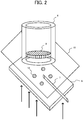
- FIG. 2 is a diagrammatic perspective view illustrating the internal configuration of a reaction measuring instrument according to Embodiment 1.
- first, humidified air flowed into the inside of the reaction measuring instrument 4 comes in contact with the first foam heat-insulating material 6 in which discharge holes 14 are formed.
- the first foam heat-insulating material 6 corresponds to simulated skin in measurement of the sorption exothermicity of the sample 10.
- inflow of the humidified air occurs from the discharge holes 14 and outflow thereof occurs toward the reverse face of the contact face of the first foam heat-insulating material 6.
- the number of the discharge holes 14 illustrated in FIG. 2 is four, the number is not limited.
- the temperature sensor 7 is placed on the reverse face of the first foam heat-insulating material 6.
- the temperature sensor 7 preferably has a film-like shape, and is affixed onto the face of the first foam heat-insulating material 6 with a pressure sensitive adhesive tape and/or the like. Further, the temperature-sensing portion of the temperature sensor 7 is placed to come in contact with the sample 10.
- the sample holder 8 sandwiches and hold the sample 10 between the sample holder 8 and the first foam heat-insulating material 6 so that the temperature-sensing portion of the temperature sensor 7 comes in contact with the sample 10 in the periphery of a region containing the temperature sensor 7.
- the sample holder 8 has a cylindrical shape, and the sample 10 adheres to the bottom thereof with a tape and/or the like.
- the sample 10 is preferably allowed to adhere to the bottom so that the temperature sensor 7 comes directly in contact with a side to be contact with a skin, whereby sorption exothermicity can be more precisely evaluated.
- the second foam heat-insulating material 9 having a circular shape is placed in the state of being packed at a spacing from the bottom, to which the sample 10 adheres, in the cylindrical shape of the sample holder 8.
- the second foam heat-insulating material 9 is placed in the state of facing the first foam heat-insulating material 6.
- Outflow of humidified air occurs from the discharge holes 14 in the first foam heat-insulating material 6 into the reaction measuring instrument 4 having such a structure, and the temperature of the sample 10 is measured with the temperature sensor 7 every predetermined time, for example, while supplying humidified air for around 30 minutes.
- the sample 10 When outflow of dry air or humidified air occurs from the discharge holes 14 in the first foam heat-insulating material 6, the sample 10 is sandwiched between the first foam heat-insulating material 6 and the second foam heat-insulating material 9 facing the first foam heat-insulating material 6, as illustrated in FIG. 1 , and temperature is precisely measured under conditions where heat radiation due to ventilation is not likely to occur. Therefore, an evaluation similar to that under circumstances where clothing is actually worn can be performed, for example, under circumstances where the temperature of the skin-contact side of the sample 10 which is a test piece of clothing as mentioned above is directly measured.
- the sorption exothermicity of the sample 10 can be evaluated by a difference between the temperature of the sample 10 in dry air and the temperature of the sample 10 in humidified air (difference between temperatures which are average temperatures or maximum end-point temperatures in measurement, or the like).
- supplementary testing is preferably conducted to exclude abnormal values.
- the inflow of humidified air that directly flows into the reaction measuring instrument 4 is measured and regulated, and therefore the amount of given moisture per unit time can be controlled.
- the evaluation results of sorption exothermicity with more accuracy and improved reproducibility can be provided.
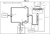
- FIG. 3 is a schematic configuration diagram illustrating sorption exothermicity measurement device according to Embodiment 2. As illustrated in FIG. 3 , the differences between the sorption exothermicity measurement device 1 according to the present embodiment 2 and the sorption exothermicity measurement device 1 according to the embodiment 1 mentioned above are in that a controller 15 is disposed between the flow rate measuring instrument 5 and the humidified air supply system needle valve 13 and in that the sorption exothermicity measurement device 1 is placed in ambient air under constant conditions.
- the measurement of sorption exothermicity in ambient air under constant conditions is preferred since the temperature of air supplied from the air pump 2 is constant and an error is not likely to occur in the evaluation of sorption exothermicity based on temperature measurement.
- the dry air supply system needle valve 12 is not always needed, and the flow rate may be set at a certain flow rate.
- the measuring method using the sorption exothermicity measurement device 1 according to the present embodiment 2 will be explained.
- the process of measuring temperature after the flowing of dry air or humidified air into the reaction measuring instrument 4 is the same as or similar to that in the embodiment 1 mentioned above. However, there is one difference from the embodiment 1 mentioned above in the process prior to the flowing of humidified air into the reaction measuring instrument 4. A detailed explanation will be given below.
- the difference is in that the flow rate of humidified air is measured by the flow rate measuring instrument 5 and judgment whether the flow rate is a flow rate within a certain range or not and further subsequent judgments are performed by the controller 15.
- the detailed process is the same as or similar to that in the embodiment 1 mentioned above, and therefore, on the basis of the difference, the method for measuring sorption exothermicity according to the present embodiment 2 will be briefly commented with a flowchart form.
- the controller 15 inputs the detected value of the flow rate from the flow rate measuring instrument 5 and regulates the humidified air supply system needle valve 13 so that the flow rate is a determined flow rate. Further, the detected value of temperature is input from the temperature sensor 7 and recorded at predetermined timing. Although not illustrated in FIG. 3 , both of the air pump 2 and the switching valve 11 may also be controlled by the controller 15 to enable air to be supplied and the flow paths to be switched automatically.
- a difference in pressure before and after a diaphragm for example, a difference in pressure before and after a plate, ultrasonic wave propagation time, or the like is measured using a diaphragm flowmeter (Venturi meter), a differential pressure flow meter, an ultrasonic flowmeter, or the like, and an electrical signal value indicating the flow rate is input.
- a diaphragm flowmeter Venturi meter
- a differential pressure flow meter an ultrasonic flowmeter, or the like
- an electrical signal value indicating the flow rate is input.
- an actuator is attached to an operator for a needle valve, and the movement of the actuator is controlled, whereby the flow rate can be regulated.
- flow rate measurement and flow rate regulation may be realized by any method.
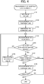
- FIG. 4 is a flowchart showing an example of the operation of the measurement of sorption exothermicity according to Embodiment 2.
- dry air is allowed to flow into the reaction measuring instrument 4 from a dry air supply system (step S101), and the temperature of the sample 10 is measured, for example, 1 to 2 minutes later (step S102).
- the flow paths are switched by the switching valve 11 so that humidified air is supplied (step S103).
- the flow rate of humidified air is measured by the flow rate measuring instrument 5 (step S104).
- step S105 it is judged whether the flow rate is within a certain range or not in the system of the controller 15 (step S105), and when the flow rate deviates from the certain range (step S105; NO), information is sent so that the regulation is automatically carried out in the humidified air supply system needle valve 13 (step S106).
- step S106 the flow rate of humidified air is appropriately regulated in the humidified air supply system needle valve 13, and a return to the stage of measuring the flow rate of humidified air is performed again (step S104).
- step S105 When the flow rate is within the certain range (determined value) (step S105; YES), if predetermined time elapses (step S107; YES), the temperature of the sample 10 is measured (step S108).
- the predetermined time corresponds to, for example, a cycle for measuring temperature.
- the predetermined time can be appropriately determined according to a regulated flow rate, the material of the sample 10, ambient conditions, or the like.
- step S107; NO a return to the stage of measuring the flow rate of humidified air is performed again (step S104).
- step S107 When the predetermined time elapses (step S107; YES), the temperature of the sample 10 is measured (step S108), and then, it is judged whether temperature measurement is finished or not (step S109). For example, when temperature measurement is performed plural times, if temperature measurement has not been finished a specified number of times (or for specified time) (step S109; NO), a return to the stage of measuring the flow rate of humidified air is performed again (step S104). When temperature measurement has been finished a specified number of times (or for a specified time) (step S109; YES), the measurement of sorption exothermicity is finished.
- the flow rate of humidified air that directly flows into the reaction measuring instrument 4 is measured and regulated in the same or similar manner as in Embodiment 1, and therefore, the amount of given moisture per unit time can be controlled.
- the evaluation results of sorption exothermicity with more accuracy and improved reproducibility can be provided.
- the method is simpler and more efficient since the controller 15 is also disposed.
- FIG. 5 is a schematic configuration diagram illustrating the sorption exothermicity measurement device 1 according to Embodiment 3.
- the difference between the sorption exothermicity measurement device 1 according to the present embodiment 3 and the sorption exothermicity measurement device 1 according to Embodiment 1 mentioned above is in that, as a whole, a plurality of reaction measuring instruments 4 and a plurality of flow rate measuring instruments 5 are disposed and a needle valve 16 is disposed between each supply flow path and each flow rate measuring instrument 5.
- a measuring method using the sorption exothermicity measurement device 1 according to the present embodiment 3 will be explained.
- the process of measuring temperature after flowing of dry air or humidified air into the plural reaction measuring instruments 4 is the same as or similar to that in Embodiments 1 and 2 mentioned above.
- performance of the sorption exothermicity measurement in ambient air under constant conditions is the same as or similar to that in Embodiment 2 mentioned above.
- Embodiment 1 and 2 mentioned above there is one difference from Embodiments 1 and 2 mentioned above. A detailed explanation will be given below.
- the process before humidified air is supplied from the bubbling instrument 3 is the same as or similar to that in which Embodiments 1 and 2 mentioned above are combined. However, then, humidified air is divided into the plural flow paths, passes through the plural needle valves 16, and flow rates are measured by flow rate measuring instruments 5 connected to respective needle valves 16.
- each measured flow rate is a flow rate within a certain range; and if the flow rate deviates from the certain range, the needle valve 16 connected to the flow rate measuring instrument 5 with the deviating flow rate is loosened or closed, for example, by manual operation to regulate the flow rate of humidified air to be a flow rate within the certain range.
- the humidified air regulated to have the flow rate within the certain range in each flow path flows into the reaction measuring instrument 4 connected to each needle valve 16 and each flow rate measuring instrument 5, and sorption exothermicity is evaluated by the same as or similar to measuring method in Embodiments 1 and 2 mentioned above.
- various kinds of test pieces can be used for the sample 10 measured in each reaction measuring instrument 4.
- the flow rate may be set at a certain flow rate in advance.
- the humidified air supply system needle valve 13 may also be used for roughly regulating the amount of supplied humidified air.
- the flow rate of humidified air that directly flows into each reaction measuring instrument 4 is measured and regulated in the same or similar manner as in Embodiment 1, and therefore, the amount of given moisture per unit time can be controlled.
- the evaluation results of sorption exothermicity with more accuracy and improved reproducibility can be provided.
- the method is simpler and more efficient since sorption exothermicity can be evaluated for a large number of samples 10 in one operation.
- FIG. 6 is a schematic configuration diagram illustrating a sorption exothermicity measurement device according to Embodiment 4. As illustrated in FIG. 6 , the difference between the sorption exothermicity measurement device 1 according to the present embodiment 4 and the sorption exothermicity measurement device 1 according to Embodiment 1 mentioned above is in that a silica gel filled tube 17 is disposed in the flow path that links the air pump 2 and the dry air supply system needle valve 12.
- a measuring method using the sorption exothermicity measurement device 1 according to the present embodiment 4 is different only in that the dry air of the air pump 2 is passed through the silica gel filled tube 17 to allow more dried air to flow into the reaction measuring instrument 4, compared to the measuring method according to Embodiment 1 mentioned above. In other words, the difference between the measurement temperature of the sample 10 in dry air and the measurement temperature of the sample 10 in humidified air is increased. Any substance that absorbs moisture, such as calcium chloride, except silica gel, may be used.
- the flow rates of dry air and humidified air that directly flow into the reaction measuring instrument 4 are measured and regulated, and therefore, the amount of given moisture per unit time can be controlled.
- the evaluation results of sorption exothermicity with more accuracy and improved reproducibility can be provided.
- the measurement temperature difference between dry air and humidified air is increased, sorption exothermicity with a minute difference can be evaluated.
- the regulation of the flow rate of air using the dry air supply system needle valve 12, the humidified air supply system needle valve 13, or the needle valve 16 may be replaced by fine adjustment using the air pump 2 or by regulation in combination of the instruments.
- a commercially available flowmeter with a valve, with which measurement and regulation of an air flow rate are simultaneously performed may be connected.
- an instrument or a method for measuring and regulating an air flow rate known to those skilled in the art, may be utilized.
- the shape, configuration, and the like of the structural instruments of the sorption exothermicity measurement device or the reaction measuring instrument 4 illustrated in FIGS. 1 to 3 , 5 , and 6 are examples. Any shape, configuration, and the like are acceptable if the temperature of a test piece can be measured and sorption exothermicity can also be evaluated under the same conditions as in the present disclosure.
- FIG. 5 The preferred embodiment illustrated in above-mentioned FIG. 5 will be explained with a specific example.
- the air supply system illustrated in FIG. 5 is configured using a commercially available instrument so that switching and supply of dry air (20°C ⁇ 40% RH) and humidified air (20°C ⁇ 90% RH) can be performed by the manual valve (switching valve 11).
- the dry air (20°C ⁇ 40% RH) is ambient air in a room with steady temperature and humidity.
- Commercially available flowmeters with valves are used as alternatives to each flow rate measuring instrument 5 and each needle valve 16.
- a first foam heat-insulating material 6 is a styrene foam plate having a thickness of 5 to 7 mm and measuring 50 mm per side, in which four discharge holes 14 ( ⁇ 5 mm) are formed on a circumference of a circle with a radius of 10 mm, and functions as simulated skin.
- a temperature sensor 7 is a film-like thin film temperature sensor and is fixed to the first foam heat-insulating material 6 with a double-faced tape.
- a sample holder 8 is a cylindrical plastic holder (40 mm in inner diameter/ 50 mm in outer diameter); and a position with a height of 2 mm from a position where a sample 10 is adhered is blocked with a styrene foam plate which is a second foam heat-insulating material 9 to form a residence air layer in measurement. Further, the sample 10 (measuring around 10 cm per side) is adhered to the bottom of the sample holder 8 with a double-faced tape without being wrinkled. In this case, the reverse side of the skin-contact side of the sample 10 which is a test piece of clothing is adhered to the sample holder 8. Then, the sample holder 8 is put on the face of the first foam heat-insulating material 6 to which the temperature sensor 7 is fixed (see FIGS. 1 and 2 ).
Landscapes
- Engineering & Computer Science (AREA)
- Chemical & Material Sciences (AREA)
- Health & Medical Sciences (AREA)
- Life Sciences & Earth Sciences (AREA)
- Textile Engineering (AREA)
- Analytical Chemistry (AREA)
- Physics & Mathematics (AREA)
- Biochemistry (AREA)
- General Health & Medical Sciences (AREA)
- General Physics & Mathematics (AREA)
- Immunology (AREA)
- Pathology (AREA)
- Medicinal Chemistry (AREA)
- Food Science & Technology (AREA)
- Chemical Kinetics & Catalysis (AREA)
- Combustion & Propulsion (AREA)
- Investigating Or Analyzing Materials Using Thermal Means (AREA)
- Measuring Volume Flow (AREA)
Applications Claiming Priority (2)
| Application Number | Priority Date | Filing Date | Title |
|---|---|---|---|
| JP2012039260A JP5503675B2 (ja) | 2012-02-24 | 2012-02-24 | 収着発熱性測定装置および測定方法 |
| PCT/JP2012/083148 WO2013125145A1 (ja) | 2012-02-24 | 2012-12-20 | 収着発熱性測定装置および収着発熱性測定方法 |
Publications (3)
| Publication Number | Publication Date |
|---|---|
| EP2818854A1 EP2818854A1 (en) | 2014-12-31 |
| EP2818854A4 EP2818854A4 (en) | 2015-10-21 |
| EP2818854B1 true EP2818854B1 (en) | 2017-02-22 |
Family
ID=49005345
Family Applications (1)
| Application Number | Title | Priority Date | Filing Date |
|---|---|---|---|
| EP12868935.3A Not-in-force EP2818854B1 (en) | 2012-02-24 | 2012-12-20 | Heat absorption/generation measurement device and heat absorption/generation measurement method |
Country Status (6)
| Country | Link |
|---|---|
| US (1) | US9297794B2 (enExample) |
| EP (1) | EP2818854B1 (enExample) |
| JP (1) | JP5503675B2 (enExample) |
| KR (1) | KR101890010B1 (enExample) |
| CN (1) | CN104115007B (enExample) |
| WO (1) | WO2013125145A1 (enExample) |
Families Citing this family (4)
| Publication number | Priority date | Publication date | Assignee | Title |
|---|---|---|---|---|
| CN104730292B (zh) * | 2015-02-12 | 2017-10-24 | 天津力神电池股份有限公司 | 一种锂离子电池嵌锂态负极电镜样品的制备及观测方法 |
| WO2017154597A1 (ja) * | 2016-03-09 | 2017-09-14 | 三菱電機株式会社 | 熱処理装置、熱処理方法、レーザアニール装置、および、レーザアニール方法 |
| CN107490597B (zh) * | 2017-09-19 | 2019-10-18 | 北京科技大学 | 一种同步热跟踪法测定溶液吸收热的装置及测定方法 |
| CN113820246A (zh) * | 2021-09-18 | 2021-12-21 | 河北省计量监督检测研究院 | 基于恒压燃烧室与天然气质量修正的尾气收集与分析系统 |
Family Cites Families (15)
| Publication number | Priority date | Publication date | Assignee | Title |
|---|---|---|---|---|
| US4496249A (en) * | 1982-09-23 | 1985-01-29 | University Of Florida | Method and apparatus for determining relative surface areas of a coated material on a substrate |
| JPS6435476A (en) * | 1987-07-30 | 1989-02-06 | Agency Ind Science Techn | Controller for amount of sweating |
| JPH0684967B2 (ja) * | 1987-11-25 | 1994-10-26 | 石川県 | 被服用布地の特性測定装置 |
| GB8907467D0 (en) * | 1989-04-03 | 1989-05-17 | Secr Defence | Thin film calorimeter |
| JP2881242B2 (ja) * | 1990-02-27 | 1999-04-12 | 富士シリシア化学株式会社 | 吸脱着量測定用装置及び吸脱着量測定方法 |
| US5342580A (en) * | 1990-04-17 | 1994-08-30 | Alan Brenner | Apparatus and method for measuring the amount of gas adsorbed on or desorbed from a solid and reactions of a gas with a solid |
| JP2873367B2 (ja) * | 1996-06-27 | 1999-03-24 | 日清紡績株式会社 | 熱及び水分移動特性測定装置 |
| US6451272B1 (en) * | 1999-12-21 | 2002-09-17 | Ethicon, Inc. | Monitoring of sterilant apparatus and method for monitoring sterilant |
| US6844198B2 (en) | 2001-04-27 | 2005-01-18 | Uop Llc | Adsorptive method for determining a surface property of a solid |
| US7141210B2 (en) | 2002-04-01 | 2006-11-28 | Palo Alto Research Center Incorporated | Apparatus and method for a nanocalorimeter for detecting chemical reactions |
| JP2003337111A (ja) | 2002-05-17 | 2003-11-28 | Japan Synthetic Textile Inspection Inst Foundation | 吸湿発熱性試験方法および試験装置 |
| JP3958731B2 (ja) * | 2003-09-26 | 2007-08-15 | 財団法人日本化学繊維検査協会 | 衣服内環境模擬測定装置および評価方法 |
| JP2006329746A (ja) | 2005-05-25 | 2006-12-07 | Mizuno Corp | 吸着熱及び熱伝導性による吸湿発熱性素材の測定装置及び測定方法 |
| JP4198152B2 (ja) * | 2005-12-22 | 2008-12-17 | 学校法人文化学園 | 模擬皮膚装置およびそれを用いた特性評価方法 |
| CN102269722B (zh) * | 2011-05-05 | 2013-05-08 | 东华大学 | 一种织物系统热防护性测试仪 |
-
2012
- 2012-02-24 JP JP2012039260A patent/JP5503675B2/ja active Active
- 2012-12-20 CN CN201280065964.3A patent/CN104115007B/zh active Active
- 2012-12-20 KR KR1020147018183A patent/KR101890010B1/ko active Active
- 2012-12-20 WO PCT/JP2012/083148 patent/WO2013125145A1/ja not_active Ceased
- 2012-12-20 EP EP12868935.3A patent/EP2818854B1/en not_active Not-in-force
- 2012-12-20 US US14/380,547 patent/US9297794B2/en not_active Expired - Fee Related
Non-Patent Citations (1)
| Title |
|---|
| None * |
Also Published As
| Publication number | Publication date |
|---|---|
| US20150037894A1 (en) | 2015-02-05 |
| CN104115007A (zh) | 2014-10-22 |
| JP2013174509A (ja) | 2013-09-05 |
| HK1201324A1 (en) | 2015-08-28 |
| JP5503675B2 (ja) | 2014-05-28 |
| CN104115007B (zh) | 2017-03-08 |
| WO2013125145A1 (ja) | 2013-08-29 |
| EP2818854A4 (en) | 2015-10-21 |
| US9297794B2 (en) | 2016-03-29 |
| EP2818854A1 (en) | 2014-12-31 |
| KR20140124751A (ko) | 2014-10-27 |
| KR101890010B1 (ko) | 2018-08-20 |
Similar Documents
| Publication | Publication Date | Title |
|---|---|---|
| CN103608673B (zh) | 用于测量对水蒸气的渗透性的装置 | |
| EP2818854B1 (en) | Heat absorption/generation measurement device and heat absorption/generation measurement method | |
| Huang | Sweating guarded hot plate test method | |
| KR100386748B1 (ko) | 열및수분이동특성측정장치 | |
| CA2816340C (en) | Sampling method for use in odor measurement | |
| CN100595561C (zh) | 一种模拟皮肤透湿性能的测试方法 | |
| US8495907B2 (en) | Method and apparatus for measuring drying time of quick wet and dried fabrics | |
| US20100326217A1 (en) | Apparatus for simulatively measuring environment of wound dressing on skin and measuring method therefor | |
| JP3958731B2 (ja) | 衣服内環境模擬測定装置および評価方法 | |
| CN1975416B (zh) | 一种织物透湿性测试装置 | |
| KR100752776B1 (ko) | 착의시스템의 단열 및 투습특성 측정장치 | |
| WO2009071900A1 (en) | Improvements in or relating to the identification of one or more vapour retention/release characteristics of a textile item | |
| JP4869833B2 (ja) | 熱抵抗及び透湿抵抗測定装置 | |
| EP3252466B1 (en) | Sweat simulator and sweat simulation method | |
| JP2013174509A5 (enExample) | ||
| HK1201324B (en) | Heat absorption/generation measurement device and heat absorption/generation measurement method | |
| JP2003279465A (ja) | 気体透過性測定装置と測定方法 | |
| JP2003337111A (ja) | 吸湿発熱性試験方法および試験装置 | |
| Huang | Review of test methods for measuring water vapour transfer properties of fabrics | |
| JP2004157086A (ja) | 吸湿放湿特性測定装置および方法 | |
| KR20100112295A (ko) | 분류식 습도발생장치 | |
| JP3121969U (ja) | 熱及び水蒸気抵抗測定装置 | |
| Ryan et al. | Experimental investigation of through air drying of tissue and towel under commercial conditions | |
| US20160349199A1 (en) | Device for Thermal Analysis of the Objects | |
| Chen et al. | Flexible micro sensors for in-situ diagnosis of proton exchange membrane fuel cell |
Legal Events
| Date | Code | Title | Description |
|---|---|---|---|
| PUAI | Public reference made under article 153(3) epc to a published international application that has entered the european phase |
Free format text: ORIGINAL CODE: 0009012 |
|
| 17P | Request for examination filed |
Effective date: 20140916 |
|
| AK | Designated contracting states |
Kind code of ref document: A1 Designated state(s): AL AT BE BG CH CY CZ DE DK EE ES FI FR GB GR HR HU IE IS IT LI LT LU LV MC MK MT NL NO PL PT RO RS SE SI SK SM TR |
|
| AX | Request for extension of the european patent |
Extension state: BA ME |
|
| DAX | Request for extension of the european patent (deleted) | ||
| REG | Reference to a national code |
Ref country code: DE Ref legal event code: R079 Ref document number: 602012029075 Country of ref document: DE Free format text: PREVIOUS MAIN CLASS: G01N0025220000 Ipc: G01N0025480000 |
|
| RA4 | Supplementary search report drawn up and despatched (corrected) |
Effective date: 20150922 |
|
| RIC1 | Information provided on ipc code assigned before grant |
Ipc: G01N 33/36 20060101ALI20150916BHEP Ipc: G01N 25/48 20060101AFI20150916BHEP |
|
| 17Q | First examination report despatched |
Effective date: 20160503 |
|
| GRAP | Despatch of communication of intention to grant a patent |
Free format text: ORIGINAL CODE: EPIDOSNIGR1 |
|
| INTG | Intention to grant announced |
Effective date: 20161007 |
|
| RAP1 | Party data changed (applicant data changed or rights of an application transferred) |
Owner name: KAKEN TEST CENTER |
|
| STAA | Information on the status of an ep patent application or granted ep patent |
Free format text: STATUS: GRANT OF PATENT IS INTENDED |
|
| GRAS | Grant fee paid |
Free format text: ORIGINAL CODE: EPIDOSNIGR3 |
|
| GRAA | (expected) grant |
Free format text: ORIGINAL CODE: 0009210 |
|
| STAA | Information on the status of an ep patent application or granted ep patent |
Free format text: STATUS: THE PATENT HAS BEEN GRANTED |
|
| AK | Designated contracting states |
Kind code of ref document: B1 Designated state(s): AL AT BE BG CH CY CZ DE DK EE ES FI FR GB GR HR HU IE IS IT LI LT LU LV MC MK MT NL NO PL PT RO RS SE SI SK SM TR |
|
| REG | Reference to a national code |
Ref country code: GB Ref legal event code: FG4D |
|
| RIN1 | Information on inventor provided before grant (corrected) |
Inventor name: KURAMOTO, KANYA Inventor name: SAITO, TOSHINOBU |
|
| REG | Reference to a national code |
Ref country code: CH Ref legal event code: EP |
|
| REG | Reference to a national code |
Ref country code: AT Ref legal event code: REF Ref document number: 869639 Country of ref document: AT Kind code of ref document: T Effective date: 20170315 |
|
| REG | Reference to a national code |
Ref country code: IE Ref legal event code: FG4D |
|
| REG | Reference to a national code |
Ref country code: DE Ref legal event code: R096 Ref document number: 602012029075 Country of ref document: DE |
|
| REG | Reference to a national code |
Ref country code: LT Ref legal event code: MG4D |
|
| REG | Reference to a national code |
Ref country code: NL Ref legal event code: MP Effective date: 20170222 |
|
| REG | Reference to a national code |
Ref country code: AT Ref legal event code: MK05 Ref document number: 869639 Country of ref document: AT Kind code of ref document: T Effective date: 20170222 |
|
| PG25 | Lapsed in a contracting state [announced via postgrant information from national office to epo] |
Ref country code: NO Free format text: LAPSE BECAUSE OF FAILURE TO SUBMIT A TRANSLATION OF THE DESCRIPTION OR TO PAY THE FEE WITHIN THE PRESCRIBED TIME-LIMIT Effective date: 20170522 Ref country code: FI Free format text: LAPSE BECAUSE OF FAILURE TO SUBMIT A TRANSLATION OF THE DESCRIPTION OR TO PAY THE FEE WITHIN THE PRESCRIBED TIME-LIMIT Effective date: 20170222 Ref country code: LT Free format text: LAPSE BECAUSE OF FAILURE TO SUBMIT A TRANSLATION OF THE DESCRIPTION OR TO PAY THE FEE WITHIN THE PRESCRIBED TIME-LIMIT Effective date: 20170222 Ref country code: HR Free format text: LAPSE BECAUSE OF FAILURE TO SUBMIT A TRANSLATION OF THE DESCRIPTION OR TO PAY THE FEE WITHIN THE PRESCRIBED TIME-LIMIT Effective date: 20170222 Ref country code: GR Free format text: LAPSE BECAUSE OF FAILURE TO SUBMIT A TRANSLATION OF THE DESCRIPTION OR TO PAY THE FEE WITHIN THE PRESCRIBED TIME-LIMIT Effective date: 20170523 |
|
| PG25 | Lapsed in a contracting state [announced via postgrant information from national office to epo] |
Ref country code: AT Free format text: LAPSE BECAUSE OF FAILURE TO SUBMIT A TRANSLATION OF THE DESCRIPTION OR TO PAY THE FEE WITHIN THE PRESCRIBED TIME-LIMIT Effective date: 20170222 Ref country code: RS Free format text: LAPSE BECAUSE OF FAILURE TO SUBMIT A TRANSLATION OF THE DESCRIPTION OR TO PAY THE FEE WITHIN THE PRESCRIBED TIME-LIMIT Effective date: 20170222 Ref country code: NL Free format text: LAPSE BECAUSE OF FAILURE TO SUBMIT A TRANSLATION OF THE DESCRIPTION OR TO PAY THE FEE WITHIN THE PRESCRIBED TIME-LIMIT Effective date: 20170222 Ref country code: ES Free format text: LAPSE BECAUSE OF FAILURE TO SUBMIT A TRANSLATION OF THE DESCRIPTION OR TO PAY THE FEE WITHIN THE PRESCRIBED TIME-LIMIT Effective date: 20170222 Ref country code: PT Free format text: LAPSE BECAUSE OF FAILURE TO SUBMIT A TRANSLATION OF THE DESCRIPTION OR TO PAY THE FEE WITHIN THE PRESCRIBED TIME-LIMIT Effective date: 20170622 Ref country code: LV Free format text: LAPSE BECAUSE OF FAILURE TO SUBMIT A TRANSLATION OF THE DESCRIPTION OR TO PAY THE FEE WITHIN THE PRESCRIBED TIME-LIMIT Effective date: 20170222 Ref country code: SE Free format text: LAPSE BECAUSE OF FAILURE TO SUBMIT A TRANSLATION OF THE DESCRIPTION OR TO PAY THE FEE WITHIN THE PRESCRIBED TIME-LIMIT Effective date: 20170222 Ref country code: BG Free format text: LAPSE BECAUSE OF FAILURE TO SUBMIT A TRANSLATION OF THE DESCRIPTION OR TO PAY THE FEE WITHIN THE PRESCRIBED TIME-LIMIT Effective date: 20170522 |
|
| PG25 | Lapsed in a contracting state [announced via postgrant information from national office to epo] |
Ref country code: RO Free format text: LAPSE BECAUSE OF FAILURE TO SUBMIT A TRANSLATION OF THE DESCRIPTION OR TO PAY THE FEE WITHIN THE PRESCRIBED TIME-LIMIT Effective date: 20170222 Ref country code: CZ Free format text: LAPSE BECAUSE OF FAILURE TO SUBMIT A TRANSLATION OF THE DESCRIPTION OR TO PAY THE FEE WITHIN THE PRESCRIBED TIME-LIMIT Effective date: 20170222 Ref country code: IT Free format text: LAPSE BECAUSE OF FAILURE TO SUBMIT A TRANSLATION OF THE DESCRIPTION OR TO PAY THE FEE WITHIN THE PRESCRIBED TIME-LIMIT Effective date: 20170222 Ref country code: SK Free format text: LAPSE BECAUSE OF FAILURE TO SUBMIT A TRANSLATION OF THE DESCRIPTION OR TO PAY THE FEE WITHIN THE PRESCRIBED TIME-LIMIT Effective date: 20170222 Ref country code: EE Free format text: LAPSE BECAUSE OF FAILURE TO SUBMIT A TRANSLATION OF THE DESCRIPTION OR TO PAY THE FEE WITHIN THE PRESCRIBED TIME-LIMIT Effective date: 20170222 |
|
| REG | Reference to a national code |
Ref country code: DE Ref legal event code: R097 Ref document number: 602012029075 Country of ref document: DE |
|
| PG25 | Lapsed in a contracting state [announced via postgrant information from national office to epo] |
Ref country code: SM Free format text: LAPSE BECAUSE OF FAILURE TO SUBMIT A TRANSLATION OF THE DESCRIPTION OR TO PAY THE FEE WITHIN THE PRESCRIBED TIME-LIMIT Effective date: 20170222 Ref country code: PL Free format text: LAPSE BECAUSE OF FAILURE TO SUBMIT A TRANSLATION OF THE DESCRIPTION OR TO PAY THE FEE WITHIN THE PRESCRIBED TIME-LIMIT Effective date: 20170222 Ref country code: DK Free format text: LAPSE BECAUSE OF FAILURE TO SUBMIT A TRANSLATION OF THE DESCRIPTION OR TO PAY THE FEE WITHIN THE PRESCRIBED TIME-LIMIT Effective date: 20170222 |
|
| REG | Reference to a national code |
Ref country code: FR Ref legal event code: PLFP Year of fee payment: 6 |
|
| PLBE | No opposition filed within time limit |
Free format text: ORIGINAL CODE: 0009261 |
|
| STAA | Information on the status of an ep patent application or granted ep patent |
Free format text: STATUS: NO OPPOSITION FILED WITHIN TIME LIMIT |
|
| 26N | No opposition filed |
Effective date: 20171123 |
|
| PG25 | Lapsed in a contracting state [announced via postgrant information from national office to epo] |
Ref country code: SI Free format text: LAPSE BECAUSE OF FAILURE TO SUBMIT A TRANSLATION OF THE DESCRIPTION OR TO PAY THE FEE WITHIN THE PRESCRIBED TIME-LIMIT Effective date: 20170222 |
|
| REG | Reference to a national code |
Ref country code: CH Ref legal event code: PL |
|
| REG | Reference to a national code |
Ref country code: IE Ref legal event code: MM4A |
|
| PG25 | Lapsed in a contracting state [announced via postgrant information from national office to epo] |
Ref country code: LU Free format text: LAPSE BECAUSE OF NON-PAYMENT OF DUE FEES Effective date: 20171220 Ref country code: MT Free format text: LAPSE BECAUSE OF NON-PAYMENT OF DUE FEES Effective date: 20171220 |
|
| REG | Reference to a national code |
Ref country code: BE Ref legal event code: MM Effective date: 20171231 |
|
| PG25 | Lapsed in a contracting state [announced via postgrant information from national office to epo] |
Ref country code: IE Free format text: LAPSE BECAUSE OF NON-PAYMENT OF DUE FEES Effective date: 20171220 |
|
| PG25 | Lapsed in a contracting state [announced via postgrant information from national office to epo] |
Ref country code: CH Free format text: LAPSE BECAUSE OF NON-PAYMENT OF DUE FEES Effective date: 20171231 Ref country code: LI Free format text: LAPSE BECAUSE OF NON-PAYMENT OF DUE FEES Effective date: 20171231 Ref country code: BE Free format text: LAPSE BECAUSE OF NON-PAYMENT OF DUE FEES Effective date: 20171231 |
|
| PG25 | Lapsed in a contracting state [announced via postgrant information from national office to epo] |
Ref country code: HU Free format text: LAPSE BECAUSE OF FAILURE TO SUBMIT A TRANSLATION OF THE DESCRIPTION OR TO PAY THE FEE WITHIN THE PRESCRIBED TIME-LIMIT; INVALID AB INITIO Effective date: 20121220 Ref country code: MC Free format text: LAPSE BECAUSE OF FAILURE TO SUBMIT A TRANSLATION OF THE DESCRIPTION OR TO PAY THE FEE WITHIN THE PRESCRIBED TIME-LIMIT Effective date: 20170222 |
|
| PG25 | Lapsed in a contracting state [announced via postgrant information from national office to epo] |
Ref country code: CY Free format text: LAPSE BECAUSE OF FAILURE TO SUBMIT A TRANSLATION OF THE DESCRIPTION OR TO PAY THE FEE WITHIN THE PRESCRIBED TIME-LIMIT Effective date: 20170222 |
|
| PG25 | Lapsed in a contracting state [announced via postgrant information from national office to epo] |
Ref country code: MK Free format text: LAPSE BECAUSE OF FAILURE TO SUBMIT A TRANSLATION OF THE DESCRIPTION OR TO PAY THE FEE WITHIN THE PRESCRIBED TIME-LIMIT Effective date: 20170222 |
|
| PG25 | Lapsed in a contracting state [announced via postgrant information from national office to epo] |
Ref country code: TR Free format text: LAPSE BECAUSE OF FAILURE TO SUBMIT A TRANSLATION OF THE DESCRIPTION OR TO PAY THE FEE WITHIN THE PRESCRIBED TIME-LIMIT Effective date: 20170222 |
|
| PG25 | Lapsed in a contracting state [announced via postgrant information from national office to epo] |
Ref country code: AL Free format text: LAPSE BECAUSE OF FAILURE TO SUBMIT A TRANSLATION OF THE DESCRIPTION OR TO PAY THE FEE WITHIN THE PRESCRIBED TIME-LIMIT Effective date: 20170222 Ref country code: IS Free format text: LAPSE BECAUSE OF FAILURE TO SUBMIT A TRANSLATION OF THE DESCRIPTION OR TO PAY THE FEE WITHIN THE PRESCRIBED TIME-LIMIT Effective date: 20170622 |
|
| PGFP | Annual fee paid to national office [announced via postgrant information from national office to epo] |
Ref country code: FR Payment date: 20211224 Year of fee payment: 10 Ref country code: DE Payment date: 20211124 Year of fee payment: 10 Ref country code: GB Payment date: 20211222 Year of fee payment: 10 |
|
| REG | Reference to a national code |
Ref country code: DE Ref legal event code: R119 Ref document number: 602012029075 Country of ref document: DE |
|
| GBPC | Gb: european patent ceased through non-payment of renewal fee |
Effective date: 20221220 |
|
| PG25 | Lapsed in a contracting state [announced via postgrant information from national office to epo] |
Ref country code: GB Free format text: LAPSE BECAUSE OF NON-PAYMENT OF DUE FEES Effective date: 20221220 Ref country code: DE Free format text: LAPSE BECAUSE OF NON-PAYMENT OF DUE FEES Effective date: 20230701 |
|
| PG25 | Lapsed in a contracting state [announced via postgrant information from national office to epo] |
Ref country code: FR Free format text: LAPSE BECAUSE OF NON-PAYMENT OF DUE FEES Effective date: 20221231 |