EP2818831A1 - Method and system for determing the postion and posture of a mobile terminal - Google Patents
Method and system for determing the postion and posture of a mobile terminal Download PDFInfo
- Publication number
- EP2818831A1 EP2818831A1 EP20140000337 EP14000337A EP2818831A1 EP 2818831 A1 EP2818831 A1 EP 2818831A1 EP 20140000337 EP20140000337 EP 20140000337 EP 14000337 A EP14000337 A EP 14000337A EP 2818831 A1 EP2818831 A1 EP 2818831A1
- Authority
- EP
- European Patent Office
- Prior art keywords
- mobile terminal
- display screen
- capturing device
- guiding
- current
- Prior art date
- Legal status (The legal status is an assumption and is not a legal conclusion. Google has not performed a legal analysis and makes no representation as to the accuracy of the status listed.)
- Ceased
Links
- 238000000034 method Methods 0.000 title claims abstract description 16
- 238000001514 detection method Methods 0.000 claims abstract description 31
- 230000001133 acceleration Effects 0.000 claims description 6
- 230000000694 effects Effects 0.000 abstract description 3
- 238000003384 imaging method Methods 0.000 description 9
- 238000010586 diagram Methods 0.000 description 5
- 230000006870 function Effects 0.000 description 5
- 230000009466 transformation Effects 0.000 description 4
- 230000008569 process Effects 0.000 description 3
- 238000004364 calculation method Methods 0.000 description 2
- 238000013500 data storage Methods 0.000 description 2
- 238000012986 modification Methods 0.000 description 2
- 230000004048 modification Effects 0.000 description 2
- 230000002159 abnormal effect Effects 0.000 description 1
- 230000005540 biological transmission Effects 0.000 description 1
- 230000008859 change Effects 0.000 description 1
- 230000007547 defect Effects 0.000 description 1
- 230000001131 transforming effect Effects 0.000 description 1
- 230000000007 visual effect Effects 0.000 description 1
Images


Classifications
-
- G—PHYSICS
- G01—MEASURING; TESTING
- G01C—MEASURING DISTANCES, LEVELS OR BEARINGS; SURVEYING; NAVIGATION; GYROSCOPIC INSTRUMENTS; PHOTOGRAMMETRY OR VIDEOGRAMMETRY
- G01C21/00—Navigation; Navigational instruments not provided for in groups G01C1/00 - G01C19/00
- G01C21/20—Instruments for performing navigational calculations
-
- G—PHYSICS
- G01—MEASURING; TESTING
- G01S—RADIO DIRECTION-FINDING; RADIO NAVIGATION; DETERMINING DISTANCE OR VELOCITY BY USE OF RADIO WAVES; LOCATING OR PRESENCE-DETECTING BY USE OF THE REFLECTION OR RERADIATION OF RADIO WAVES; ANALOGOUS ARRANGEMENTS USING OTHER WAVES
- G01S19/00—Satellite radio beacon positioning systems; Determining position, velocity or attitude using signals transmitted by such systems
- G01S19/38—Determining a navigation solution using signals transmitted by a satellite radio beacon positioning system
- G01S19/39—Determining a navigation solution using signals transmitted by a satellite radio beacon positioning system the satellite radio beacon positioning system transmitting time-stamped messages, e.g. GPS [Global Positioning System], GLONASS [Global Orbiting Navigation Satellite System] or GALILEO
- G01S19/42—Determining position
- G01S19/45—Determining position by combining measurements of signals from the satellite radio beacon positioning system with a supplementary measurement
- G01S19/47—Determining position by combining measurements of signals from the satellite radio beacon positioning system with a supplementary measurement the supplementary measurement being an inertial measurement, e.g. tightly coupled inertial
Definitions
- the present invention relates to the technical field of position navigation, more specifically, to a method and a system for guiding the position.
- GPS Global Positioning System
- the GPS navigator is generally applied to the carried mobile terminal of the user, such as the mobile phone or the tablet computer, which is portable and is of the multiple functions in a terminal device simultaneously.
- the traditional mobile terminal with the GPS navigation function is with the following navigation problems.
- the accuracy of navigation is not high. Sometimes the range is within the radius of 500-1000 meters, which is not conducive for the user to find the destination.
- the navigation system when the user uses the navigation system, the navigation system is not able to determine the position of user accurately, thereby the navigation system is not able to determine or postpones determining the direction of moving, which brings a big trouble in the navigation.
- Chinese Patent Publication No. CN101179851 discloses a positioning system of the navigation mobile phone and the method thereof, a system service center and a navigation mobile phone, wherein a tracking module and a positioning module are configured in the navigation mobile phone.
- the positioning module is used for acquiring the current GPS positioning information of the navigation mobile phone and transmitting it to the service center.
- the tracking module is used for acquiring the SIM card information and the current GPS positioning information of the navigation mobile phone and transmitting them to the service center by the wireless transmission, when the service center detected that the identity of the user is abnormal.
- the above technical scheme does not cover the location the current posture of the mobile terminal.
- Chinese patent Publication No. CN101039475 discloses a method of realizing the mutual navigation of the mobile phone, which comprises the following steps: A, determining the target address that needs to be assisted; B, the transmitting terminal acquires the navigation database to configure the target address and transmits it to the receiving terminal; C, according to the received target address information, the receiving terminal calls the navigation database to make the path planning for the target address and feeds back the results of the path planning to the transmitting terminal.
- the invention is based on the application of MMS/GSM/GPRS/WAP communication network.
- the smart phone of the coadjutant and the mastery degree of the rode conditions By the smart phone of the coadjutant and the mastery degree of the rode conditions, the other people can be assisted to perform the navigation and to inquire easily, which avoids the problem that the mobile phones of different types used by the two parties will not perform the mutual navigation.
- the range of the applications is widened.
- the above technical scheme does not cover the location the current posture of the mobile terminal.
- the present invention provides a system for guiding the position and the method thereof, comprising:
- the angular speed detection component is the angular speed sensor of the mobile terminal
- the angular speed sensor is a three-axis acceleration sensor.
- the direction detection component is a magnetic sensor.
- the system further comprises an image capturing device which is connected to the display screen of the mobile terminal; the image capturing device is used for capturing the image data around the user and displaying the image data on the display screen of the mobile terminal.
- the system further comprises an indication device which is connected to the display screen of the mobile terminal; the indication device determines the deviation of the direction between the image capturing device and the target position according to the image data shown on the display screen and alerts the user by displaying the corresponding indication information on the display screen.
- the image capturing device is a camera.
- the positioning component is a GPS device and/or a wireless network positioning device.
- the position capturing device further comprises an altitude detection component which is used for capturing the current position of the mobile terminal in altitude; the information indicating the current position in altitude is included in the information indicating the current position.
- the altitude detection component is a barometer.
- a method for guiding the position applied to the mobile terminal wherein the above system for guiding the position is adopted, comprises:
- the image capturing device which is connected to the display screen of the mobile terminal; the image capturing device is used for capturing the image data around the user and for displaying the image data on the display screen of the mobile terminal;
- the advantageous effects of the technical scheme are that as follows: adopting the position capturing device to locate the current position and the target position of the mobile terminal simultaneously, and determining the data of the current posture and the data of the direction of the mobile terminal, which makes the navigation more accurately and meets the requirement of the user.
- the traditional mobile terminal with the GPS function is unable to capture the position of the mobile terminal itself accurately, such as the angle, direction and so on. Therefore, the general location of the mobile terminal can be captured; however the altitude of the position where the mobile terminal is located, for example, on the ground or on the second floor, or the current direction of the mobile terminal is not determined. Hence, it is necessary to invent a system for accurately guiding the position of the mobile terminal.
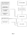
- the system for guiding the position as shown in Figure 1 which comprises a position capturing device and a treatment device.
- the position capturing device is connected to the treatment device.
- the treatment device is connected to the display screen of the mobile terminal.
- the position capturing device comprises an angular speed detection component, a positioning component and a direction detection component.
- the positioning component is a GPS device and/or a wireless (WiFi) network positioning device, i.e., the locating can be performed by adopting the GPS device or the wireless network positioning device or the combination of the GPS device and the wireless network positioning device.
- the GPS device is adopted for positioning
- the mobile terminal calculates the longitude and latitude of the position where the mobile terminal is located by the remote navigation satellites for locating;
- the WiFi component is adopted for positioning, the mobile terminal acquires the signals by a plurality of surrounding base stations, and locates the current position of the mobile terminal by the comprehensive calculation according to the positions of a plurality of the base stations.
- the positioning component can also locate the position of the destination preconfigured by the user by means of the GPS navigation and the WiFi navigation.
- the direction detection component is a magnetic sensor. Further, the direction detection component is an electronic compass.
- the electronic compass is configured in the mobile terminal, and it is used for determining the direction of the mobile terminal.
- the terminal close to the display screen is defined as the front terminal, i.e., the direction that the front terminal of the mobile terminal faces is the direction of the mobile terminal.
- the electronic compass will effect only if the mobile terminal is placed vertically or horizontally.
- the electronic compass can not detect the current direction of the mobile terminal accurately due to the rotation for a certain angle. Therefore, it is necessary to set an angular speed detection component in the mobile terminal.
- the angular speed detection component is an angular speed sensor.
- a three-axis acceleration sensor is adopted as the angular speed detection component in the embodiment of the present invention.
- the direction of the electronic compass can be adjusted according to the current posture including the rotation angle and the angular speed thereof. Consequently, the direction of the electronic compass will face to the real direction.
- the mobile terminal When the angular speed sensor is not configured in the mobile terminal, during the process of using the said system, the mobile terminal must be placed vertically in the condition that the electronic compass and the mobile terminal are configured vertically, or the mobile terminal must be placed horizontally in the condition that the electronic compass and the mobile terminal are configured horizontally.
- the electronic compass is configured perpendicular to the mobile terminal. Hence, without the corresponding angular speed sensor, the mobile terminal shall be placed perpendicular to the ground when using the said system.
- the system generally further comprises an altitude detection component.
- the altitude detection component may be a barometer which detects the current altitude variation of the mobile terminal based on the air pressure variation to determine the altitude intercept between the mobile terminal and the target position and to detect the current position of the mobile terminal more accurately.
- the system further comprises an image capturing device which may be a camera equipped on the mobile terminal.
- the camera can be provided with an indication device capable of displaying the corresponding indication information on the display screen of the mobile terminal.
- the indication device When the camera faces toward the direction of the target position accurately, the indication device will alert the user, and the user can see the objects around the target position collected by the camera on the display screen.
- the indication device When the camera does not face toward the direction of the target position, the indication device will alert the user by displaying the indication information on the display screen.
- the indication information may be the indicating arrow.
- the above image data for displaying the objects and the corresponding indication information can be shown within a smaller display area at the corner of the display screen to avoid covering the main display area of the route.
- the image capturing device can be the camera located at the rear cover of the mobile terminal.
- the purpose of configuring the camera at the rear cover is to enable the user to observe the image data while collecting the same. Hence, it is necessary to make sure that the camera and the display screen are located at the both two sides of the mobile terminal.
- the camera is used for assisting the user to locate the target position that the user wants to seek for.
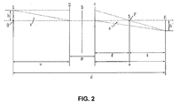
- Figure 2 shows a schematic diagram of the lens imaging.
- the height of Object O on the observed Object Plane 1 is h.
- the imaging height on Imaging Plane 6 is h'.
- the distance between Object Plane 1 and Imaging Plane 6 is the focus distance d.
- the distance between Object Plane 1 and Front Main Surface 2 of Lens 3 is the object distance u.
- the distance between Front Main Surface 2 of Lens 3 and Rare Main Surface 4 is the main point spacing p.
- the distance between Rare Main Surface 4 of Lens 3 and Imaging Plane 6 is the image distance v.
- the distance between Rare Main Surface 4 and Focal Plane 5 with the focus F is the focal plane f.
- the distance between Focal Plane 5 and Imaging Plane 6 is the focal image distance i.
- the focus distance d between the lens and the object can be calculated according to the focal distance f, the magnification M and the main point spacing p of the lens.
- the focus distance d can be calculated by the formula (3), when the image of the object located in a certain place is being collected.
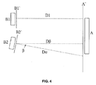
- the mobile terminal held by the user is parallel to the object image plane of the observed object.
- A denotes the object to be observed.
- A' denotes the object image plane.
- the mobile terminal B1 held by the user is parallel to the object image plane A' of the object A, and the focus distance d is the vertical distance D1' between the center of the projection plane B1' where the mobile terminal is located and the object image plane A'.
- the vertical line is also the vertical distance d between the projection plane B1' and the object image plane A'. Therefore, the vertical distance D between the projection plane B1' and the object image plane A' can be calculated directly by the formula (3).
- the user often observes the object by different observing angles, i.e., there is a certain horizontal and the vertical angle between the projection plane B2' of the mobile terminal B2 and the object image plane A'.
- the focus distance d does not equal to the vertical distance D between the center of the projection plane B2' and the object image plane A'.
- the vertical distance between the projection plane B2' and the object image plane A' is calculated respectively based on the component of the angle ⁇ between the projection plane B2' and the horizontal and the corresponding component of the angle ⁇ between the projection plane B2' and the vertical.
- the system is able to get the component of the angle which forms by rotating the mobile terminal relative to the horizontal.
- the focal distance f of the camera and the magnification M used for observing the object currently can be acquired. Therefore, according to the formula (3), the system can measure and calculate the focus distance d.
- the system acquires the vertical distance D between the projection plane and the object image plane according to the component of the vertical distance D ⁇ and D ⁇ .
- the position capturing device When the position capturing device captures the current position and the real direction of the mobile terminal and the preconfigured destination position, the position capturing device transmits the data package to the treatment device.
- the data package includes the above current position, the real direction that the mobile terminal faces to and the position of the destination.
- the treatment device acquires the route between the current position and the target position according to the map data inside and changes the results according to the current position which is continuously changed and the real direction.
- the map data inside the treatment device can be a three-dimensional map model, and what is displayed on the screen is a part of the plane projection of the three-dimensional model.
- the three-dimensional model is configured with the x-y-z coordinate system.
- the x-y-z coordinate system is corresponding to the direction of the coordinate system of the object in the real world.
- the direction of the mobile terminal is not always pointing to the target position during the navigation, i.e., the target position is not always in front of the user.
- the posture of the mobile terminal will not remain unchanged during the process of locating.
- a u-v-w coordinate system with the origin e is established, wherein the v-axis is located in the plane gt composed of the vector g and the vector t.
- the w-axis points to the opposite direction with the vector g.
- the u-axis is perpendicular to the w-v plane.
- the origin e, vector g and vector t will be changed correspondingly.
- the above u-v-w coordinate system will also be varied with the change of the vector g, the vector t and the origin vector e correspondingly. Therefore, the u-v-w coordinate system actually is the coordinate system representing the posture of the mobile terminal.
- ( x u , y u , z u ) represents the relative offset coordinate of the vertex A of the line segment a in the x-y-z coordinate system corresponding to that in the u-axis of the u-v-w coordinate system.
- (x v , y v , z v ) represents the relative offset coordinate of the vertex A in the x-y-z coordinate system corresponding to that in the v-axis of the u-v-w coordinate system.
- ( x w , y w , z w ) represents the relative offset coordinate of the vertex A in the x-y-z coordinate system corresponding to that in the w-axis of the u-v-w coordinate system.
- ( x e , y e , z e ) represents the relative offset coordinate of the origin e which is located in the u-v-w coordinate system in the x-y-z coordinate system.
- the three-axis acceleration sensor in the mobile terminal can be adopted to measure and calculate the deflection angle of each coordinate axis in the u-v-w coordinate system relative to the corresponding coordinate axis in the x-y-z coordinate system, i.e., the deflection angle between the mobile terminal and the x-y-z coordinate system along each axis direction. Acquiring the position offset from the origin e of the u-v-w coordinate system to the origin o of the x-y-z coordinate system.
- the coordinate of the corresponding point in the x-y-z coordinate system can be acquired just by multiplying the coordinate in the u-v-w coordinate system with the M v .
- the target position it is located in the three-dimensional map of the mobile terminal, and the projection thereof is displayed on the display screen of the mobile terminal.
- the coordinate of the target position P on the three-dimensional map is the coordinate in the x-y-z coordinate system, which can be calculated as P (x p , y p , z p ) .
- the coordinate of the target position P in the u-v-w coordinate system can be calculated as P (u p , v p , w p ).
- the coordinate of the projection of the target position at a projection plane in the u-v-w coordinate system can be calculated as P s ( u ps , v ps , w ps ).
- d es is the coordinate distance from the projection plane to the u-v plane, i.e., the distance from the point of the target position projected on a projection plane to the u-v plane.
- the coordinate of the target position projected onto the projection plane is calculated as to the plane coordinate ( u ps , v ps ), i.e., the plane coordinate of the target position P which has been transformed and displayed corresponding to the variation of the posture of the mobile terminal on the display screen is ( u ps , v ps ).
- the treatment device comprises a storage component which is not shown.
- the treatment device is connected to the external data storage server by a communication device.
- the treatment device is used for acquiring the latest map data in the data storage server and storing it in the storage component.
- the storage component can be a non-volatile memory or a volatile memory.
- the storage component can also comprise a storage and an internal storage.
- Figure 7 shows the specific steps of the method for guiding the position in the embodiment of the present invention, where it comprises:
- the position capturing device transmits the data package which is updated periodically at intervals of a certain time.
- the certain time is preconfigured by the developer or configured by the user.
- the user will see the route shown on a digital map and the real-time updated direction for moving of the user and the height of the position where the user locates currently (if there is a barometer inside).
- the above visual data can help the user to find the destination easily.
Landscapes
- Engineering & Computer Science (AREA)
- Radar, Positioning & Navigation (AREA)
- Remote Sensing (AREA)
- Physics & Mathematics (AREA)
- General Physics & Mathematics (AREA)
- Computer Networks & Wireless Communication (AREA)
- Automation & Control Theory (AREA)
- Navigation (AREA)
Applications Claiming Priority (1)
| Application Number | Priority Date | Filing Date | Title |
|---|---|---|---|
| CN201310264614.6A CN103453901B (zh) | 2013-06-27 | 2013-06-27 | 一种位置指引系统及位置指引方法 |
Publications (1)
| Publication Number | Publication Date |
|---|---|
| EP2818831A1 true EP2818831A1 (en) | 2014-12-31 |
Family
ID=49736529
Family Applications (1)
| Application Number | Title | Priority Date | Filing Date |
|---|---|---|---|
| EP20140000337 Ceased EP2818831A1 (en) | 2013-06-27 | 2014-01-29 | Method and system for determing the postion and posture of a mobile terminal |
Country Status (5)
| Country | Link |
|---|---|
| US (1) | US9612314B2 (enExample) |
| EP (1) | EP2818831A1 (enExample) |
| CN (1) | CN103453901B (enExample) |
| IN (1) | IN2014MN00293A (enExample) |
| WO (1) | WO2014206067A1 (enExample) |
Cited By (2)
| Publication number | Priority date | Publication date | Assignee | Title |
|---|---|---|---|---|
| CN104697481A (zh) * | 2015-01-06 | 2015-06-10 | 中国石油大学(华东) | 基于三轴加速度传感器的抽油机悬点位移测量装置及方法 |
| CN114786254A (zh) * | 2022-04-22 | 2022-07-22 | 武汉中科医疗科技工业技术研究院有限公司 | 定位方法、装置、计算机设备、存储介质和程序产品 |
Families Citing this family (10)
| Publication number | Priority date | Publication date | Assignee | Title |
|---|---|---|---|---|
| CN103453901B (zh) * | 2013-06-27 | 2016-09-28 | 展讯通信(上海)有限公司 | 一种位置指引系统及位置指引方法 |
| CN104159036B (zh) * | 2014-08-26 | 2018-09-18 | 惠州Tcl移动通信有限公司 | 一种图像方向信息的显示方法及拍摄设备 |
| JP6608456B2 (ja) * | 2015-10-05 | 2019-11-20 | パイオニア株式会社 | 推定装置、制御方法、プログラム及び記憶媒体 |
| CN106911861A (zh) * | 2017-03-24 | 2017-06-30 | 上海与德科技有限公司 | 一种基于虹膜识别的信息展示方法和装置 |
| CN109556603A (zh) * | 2018-11-19 | 2019-04-02 | 惠州Tcl移动通信有限公司 | 移动终端及其导航时出发方向的确定方法 |
| CN113196325A (zh) * | 2018-12-26 | 2021-07-30 | 深圳市柔宇科技股份有限公司 | 广告路径规划方法、穿戴装置、服务器及相关装置 |
| CN110631586A (zh) * | 2019-09-26 | 2019-12-31 | 珠海市一微半导体有限公司 | 基于视觉slam的地图构建的方法、导航系统及装置 |
| CN113572665B (zh) | 2020-04-26 | 2022-07-12 | 华为技术有限公司 | 一种确定操控目标的方法、移动设备及网关 |
| CN112860823B (zh) * | 2021-01-08 | 2022-03-11 | 腾讯科技(深圳)有限公司 | 终端指向的显示方法、装置和存储介质及电子设备 |
| CN115209397B (zh) * | 2021-04-12 | 2023-08-15 | 中国移动通信集团河北有限公司 | 潜在用户终端的确定方法、装置、设备及计算机存储介质 |
Citations (6)
| Publication number | Priority date | Publication date | Assignee | Title |
|---|---|---|---|---|
| US6430498B1 (en) * | 1999-07-12 | 2002-08-06 | Hitachi, Ltd. | Portable terminal with the function of walking navigation |
| US20060074549A1 (en) * | 2004-10-01 | 2006-04-06 | Hitachi, Ltd. | Navigation apparatus |
| WO2006109527A1 (ja) * | 2005-03-30 | 2006-10-19 | National University Corporation Kumamoto University | ナビゲーション装置およびナビゲーション方法 |
| CN101039475A (zh) | 2007-02-14 | 2007-09-19 | 深圳市赛格导航科技股份有限公司 | 一种实现手机互助导航的方法及系统 |
| CN101179851A (zh) | 2007-11-23 | 2008-05-14 | 深圳市赛格导航科技股份有限公司 | 导航手机的定位系统及方法 |
| US20080154494A1 (en) * | 2006-12-20 | 2008-06-26 | Hitachi Software Engineering Co., Ltd. | Image-related information displaying system |
Family Cites Families (11)
| Publication number | Priority date | Publication date | Assignee | Title |
|---|---|---|---|---|
| US6037936A (en) * | 1993-09-10 | 2000-03-14 | Criticom Corp. | Computer vision system with a graphic user interface and remote camera control |
| HK1044052B (zh) * | 1998-12-23 | 2005-02-04 | 阿苏拉布股份有限公司 | 提供气压计或高度计读数的手表及其制造方法 |
| IL174412A0 (en) * | 2006-03-20 | 2006-12-31 | Israel Rom | A device for orientation, navigation, and target acquisition and a method of use thereof |
| JP2009042186A (ja) * | 2007-08-10 | 2009-02-26 | Aisin Aw Co Ltd | ナビゲーション装置、サーバ、及びナビゲーションプログラム |
| JP4752923B2 (ja) * | 2009-02-02 | 2011-08-17 | 株式会社デンソー | 車載ナビゲーションシステム |
| CN101852617B (zh) * | 2009-03-30 | 2013-05-15 | 宏达国际电子股份有限公司 | 兴趣点方位的指示方法及系统 |
| TWI412730B (zh) * | 2009-06-08 | 2013-10-21 | Wistron Corp | 用於一智慧型手持裝置之測距方法及測距裝置、辨識標的物之位置的方法及電子裝置以及辨識當前位置的方法及電子裝置 |
| JP5574162B2 (ja) * | 2010-05-27 | 2014-08-20 | 株式会社リコー | 位置情報記録装置、同装置を備える撮像装置および位置情報記録方法 |
| US8694251B2 (en) * | 2010-11-25 | 2014-04-08 | Texas Instruments Incorporated | Attitude estimation for pedestrian navigation using low cost mems accelerometer in mobile applications, and processing methods, apparatus and systems |
| KR101873525B1 (ko) * | 2011-12-08 | 2018-07-03 | 삼성전자 주식회사 | 휴대단말기의 콘텐츠 표시장치 및 방법 |
| CN103453901B (zh) * | 2013-06-27 | 2016-09-28 | 展讯通信(上海)有限公司 | 一种位置指引系统及位置指引方法 |
-
2013
- 2013-06-27 CN CN201310264614.6A patent/CN103453901B/zh active Active
-
2014
- 2014-01-09 IN IN293MUN2014 patent/IN2014MN00293A/en unknown
- 2014-01-09 WO PCT/CN2014/070416 patent/WO2014206067A1/en not_active Ceased
- 2014-01-09 US US14/236,015 patent/US9612314B2/en active Active
- 2014-01-29 EP EP20140000337 patent/EP2818831A1/en not_active Ceased
Patent Citations (6)
| Publication number | Priority date | Publication date | Assignee | Title |
|---|---|---|---|---|
| US6430498B1 (en) * | 1999-07-12 | 2002-08-06 | Hitachi, Ltd. | Portable terminal with the function of walking navigation |
| US20060074549A1 (en) * | 2004-10-01 | 2006-04-06 | Hitachi, Ltd. | Navigation apparatus |
| WO2006109527A1 (ja) * | 2005-03-30 | 2006-10-19 | National University Corporation Kumamoto University | ナビゲーション装置およびナビゲーション方法 |
| US20080154494A1 (en) * | 2006-12-20 | 2008-06-26 | Hitachi Software Engineering Co., Ltd. | Image-related information displaying system |
| CN101039475A (zh) | 2007-02-14 | 2007-09-19 | 深圳市赛格导航科技股份有限公司 | 一种实现手机互助导航的方法及系统 |
| CN101179851A (zh) | 2007-11-23 | 2008-05-14 | 深圳市赛格导航科技股份有限公司 | 导航手机的定位系统及方法 |
Cited By (2)
| Publication number | Priority date | Publication date | Assignee | Title |
|---|---|---|---|---|
| CN104697481A (zh) * | 2015-01-06 | 2015-06-10 | 中国石油大学(华东) | 基于三轴加速度传感器的抽油机悬点位移测量装置及方法 |
| CN114786254A (zh) * | 2022-04-22 | 2022-07-22 | 武汉中科医疗科技工业技术研究院有限公司 | 定位方法、装置、计算机设备、存储介质和程序产品 |
Also Published As
| Publication number | Publication date |
|---|---|
| IN2014MN00293A (enExample) | 2015-06-19 |
| US9612314B2 (en) | 2017-04-04 |
| US20160252605A1 (en) | 2016-09-01 |
| CN103453901B (zh) | 2016-09-28 |
| WO2014206067A1 (en) | 2014-12-31 |
| CN103453901A (zh) | 2013-12-18 |
Similar Documents
| Publication | Publication Date | Title |
|---|---|---|
| US9612314B2 (en) | Method and system for guiding the position | |
| CN107505644B (zh) | 基于车载多传感器融合的三维高精度地图生成系统及方法 | |
| EP1760430B1 (en) | Geographic data collecting system | |
| EP2098820B1 (en) | Geographical data collecting device | |
| CN101451852B (zh) | 导航设备和导航方法 | |
| CN102338639B (zh) | 信息处理设备和信息处理方法 | |
| EP2737338B1 (en) | Method for ensuring continuity of service of a personal navigation device and device thereof | |
| US10613231B2 (en) | Portable GNSS survey system | |
| EP2312330A1 (en) | Graphics-aided remote position measurement with handheld geodesic device | |
| CN104280036B (zh) | 一种交通信息的检测与定位方法、装置及电子设备 | |
| CN107734449B (zh) | 一种基于光标签的室外辅助定位方法、系统及设备 | |
| US20150071493A1 (en) | Information processing apparatus, control method of the information processing apparatus, and storage medium | |
| JP2007232690A (ja) | 現在地検出装置、地図表示装置、および現在地検出方法 | |
| JP2001503134A (ja) | 携帯可能な手持ちデジタル地理データ・マネージャ | |
| CN104748739B (zh) | 一种智能机增强现实实现方法 | |
| CN103017740A (zh) | 一种利用视频监控装置对监控目标的定位方法及定位系统 | |
| US20160169662A1 (en) | Location-based facility management system using mobile device | |
| CN105509716A (zh) | 一种基于增强现实技术的地理信息采集方法及装置 | |
| CN111191596B (zh) | 一种封闭区域制图方法、装置及存储介质 | |
| CN111323029B (zh) | 导航方法及车载终端 | |
| CN113137970A (zh) | 小程序ar导航系统 | |
| CN102506837A (zh) | 终端定位方法及带有电子罗盘的终端 | |
| US20160188141A1 (en) | Electronic device and method for displaying target object thereof | |
| KR19990017468A (ko) | 상대 위치 측정장치 | |
| KR20150019085A (ko) | 위치 측정 시스템 및 그 방법 |
Legal Events
| Date | Code | Title | Description |
|---|---|---|---|
| PUAI | Public reference made under article 153(3) epc to a published international application that has entered the european phase |
Free format text: ORIGINAL CODE: 0009012 |
|
| 17P | Request for examination filed |
Effective date: 20140129 |
|
| AK | Designated contracting states |
Kind code of ref document: A1 Designated state(s): AL AT BE BG CH CY CZ DE DK EE ES FI FR GB GR HR HU IE IS IT LI LT LU LV MC MK MT NL NO PL PT RO RS SE SI SK SM TR |
|
| AX | Request for extension of the european patent |
Extension state: BA ME |
|
| STAA | Information on the status of an ep patent application or granted ep patent |
Free format text: STATUS: THE APPLICATION HAS BEEN REFUSED |
|
| 18R | Application refused |
Effective date: 20161008 |