EP2818791A1 - Kraftfahrzeugbeleuchtungseinrichtung mit einer Einkoppeloptik und einer Transport- und Umformoptik - Google Patents
Kraftfahrzeugbeleuchtungseinrichtung mit einer Einkoppeloptik und einer Transport- und Umformoptik Download PDFInfo
- Publication number
- EP2818791A1 EP2818791A1 EP14170653.1A EP14170653A EP2818791A1 EP 2818791 A1 EP2818791 A1 EP 2818791A1 EP 14170653 A EP14170653 A EP 14170653A EP 2818791 A1 EP2818791 A1 EP 2818791A1
- Authority
- EP
- European Patent Office
- Prior art keywords
- light
- optics
- lighting device
- motor vehicle
- vehicle lighting
- Prior art date
- Legal status (The legal status is an assumption and is not a legal conclusion. Google has not performed a legal analysis and makes no representation as to the accuracy of the status listed.)
- Withdrawn
Links
Images



Classifications
-
- G—PHYSICS
- G02—OPTICS
- G02B—OPTICAL ELEMENTS, SYSTEMS OR APPARATUS
- G02B6/00—Light guides; Structural details of arrangements comprising light guides and other optical elements, e.g. couplings
- G02B6/0001—Light guides; Structural details of arrangements comprising light guides and other optical elements, e.g. couplings specially adapted for lighting devices or systems
- G02B6/0011—Light guides; Structural details of arrangements comprising light guides and other optical elements, e.g. couplings specially adapted for lighting devices or systems the light guides being planar or of plate-like form
- G02B6/0013—Means for improving the coupling-in of light from the light source into the light guide
- G02B6/0015—Means for improving the coupling-in of light from the light source into the light guide provided on the surface of the light guide or in the bulk of it
- G02B6/0018—Redirecting means on the surface of the light guide
-
- F—MECHANICAL ENGINEERING; LIGHTING; HEATING; WEAPONS; BLASTING
- F21—LIGHTING
- F21S—NON-PORTABLE LIGHTING DEVICES; SYSTEMS THEREOF; VEHICLE LIGHTING DEVICES SPECIALLY ADAPTED FOR VEHICLE EXTERIORS
- F21S41/00—Illuminating devices specially adapted for vehicle exteriors, e.g. headlamps
- F21S41/20—Illuminating devices specially adapted for vehicle exteriors, e.g. headlamps characterised by refractors, transparent cover plates, light guides or filters
- F21S41/24—Light guides
-
- F—MECHANICAL ENGINEERING; LIGHTING; HEATING; WEAPONS; BLASTING
- F21—LIGHTING
- F21S—NON-PORTABLE LIGHTING DEVICES; SYSTEMS THEREOF; VEHICLE LIGHTING DEVICES SPECIALLY ADAPTED FOR VEHICLE EXTERIORS
- F21S43/00—Signalling devices specially adapted for vehicle exteriors, e.g. brake lamps, direction indicator lights or reversing lights
- F21S43/10—Signalling devices specially adapted for vehicle exteriors, e.g. brake lamps, direction indicator lights or reversing lights characterised by the light source
- F21S43/13—Signalling devices specially adapted for vehicle exteriors, e.g. brake lamps, direction indicator lights or reversing lights characterised by the light source characterised by the type of light source
- F21S43/14—Light emitting diodes [LED]
-
- F—MECHANICAL ENGINEERING; LIGHTING; HEATING; WEAPONS; BLASTING
- F21—LIGHTING
- F21S—NON-PORTABLE LIGHTING DEVICES; SYSTEMS THEREOF; VEHICLE LIGHTING DEVICES SPECIALLY ADAPTED FOR VEHICLE EXTERIORS
- F21S43/00—Signalling devices specially adapted for vehicle exteriors, e.g. brake lamps, direction indicator lights or reversing lights
- F21S43/20—Signalling devices specially adapted for vehicle exteriors, e.g. brake lamps, direction indicator lights or reversing lights characterised by refractors, transparent cover plates, light guides or filters
- F21S43/235—Light guides
- F21S43/236—Light guides characterised by the shape of the light guide
- F21S43/239—Light guides characterised by the shape of the light guide plate-shaped
-
- F—MECHANICAL ENGINEERING; LIGHTING; HEATING; WEAPONS; BLASTING
- F21—LIGHTING
- F21S—NON-PORTABLE LIGHTING DEVICES; SYSTEMS THEREOF; VEHICLE LIGHTING DEVICES SPECIALLY ADAPTED FOR VEHICLE EXTERIORS
- F21S43/00—Signalling devices specially adapted for vehicle exteriors, e.g. brake lamps, direction indicator lights or reversing lights
- F21S43/20—Signalling devices specially adapted for vehicle exteriors, e.g. brake lamps, direction indicator lights or reversing lights characterised by refractors, transparent cover plates, light guides or filters
- F21S43/235—Light guides
- F21S43/236—Light guides characterised by the shape of the light guide
- F21S43/241—Light guides characterised by the shape of the light guide of complex shape
-
- F—MECHANICAL ENGINEERING; LIGHTING; HEATING; WEAPONS; BLASTING
- F21—LIGHTING
- F21S—NON-PORTABLE LIGHTING DEVICES; SYSTEMS THEREOF; VEHICLE LIGHTING DEVICES SPECIALLY ADAPTED FOR VEHICLE EXTERIORS
- F21S43/00—Signalling devices specially adapted for vehicle exteriors, e.g. brake lamps, direction indicator lights or reversing lights
- F21S43/20—Signalling devices specially adapted for vehicle exteriors, e.g. brake lamps, direction indicator lights or reversing lights characterised by refractors, transparent cover plates, light guides or filters
- F21S43/235—Light guides
- F21S43/242—Light guides characterised by the emission area
- F21S43/243—Light guides characterised by the emission area emitting light from one or more of its extremities
-
- F—MECHANICAL ENGINEERING; LIGHTING; HEATING; WEAPONS; BLASTING
- F21—LIGHTING
- F21S—NON-PORTABLE LIGHTING DEVICES; SYSTEMS THEREOF; VEHICLE LIGHTING DEVICES SPECIALLY ADAPTED FOR VEHICLE EXTERIORS
- F21S43/00—Signalling devices specially adapted for vehicle exteriors, e.g. brake lamps, direction indicator lights or reversing lights
- F21S43/20—Signalling devices specially adapted for vehicle exteriors, e.g. brake lamps, direction indicator lights or reversing lights characterised by refractors, transparent cover plates, light guides or filters
- F21S43/26—Refractors, transparent cover plates, light guides or filters not provided in groups F21S43/235 - F21S43/255
-
- F—MECHANICAL ENGINEERING; LIGHTING; HEATING; WEAPONS; BLASTING
- F21—LIGHTING
- F21S—NON-PORTABLE LIGHTING DEVICES; SYSTEMS THEREOF; VEHICLE LIGHTING DEVICES SPECIALLY ADAPTED FOR VEHICLE EXTERIORS
- F21S43/00—Signalling devices specially adapted for vehicle exteriors, e.g. brake lamps, direction indicator lights or reversing lights
- F21S43/20—Signalling devices specially adapted for vehicle exteriors, e.g. brake lamps, direction indicator lights or reversing lights characterised by refractors, transparent cover plates, light guides or filters
- F21S43/27—Attachment thereof
-
- F—MECHANICAL ENGINEERING; LIGHTING; HEATING; WEAPONS; BLASTING
- F21—LIGHTING
- F21S—NON-PORTABLE LIGHTING DEVICES; SYSTEMS THEREOF; VEHICLE LIGHTING DEVICES SPECIALLY ADAPTED FOR VEHICLE EXTERIORS
- F21S43/00—Signalling devices specially adapted for vehicle exteriors, e.g. brake lamps, direction indicator lights or reversing lights
- F21S43/30—Signalling devices specially adapted for vehicle exteriors, e.g. brake lamps, direction indicator lights or reversing lights characterised by reflectors
- F21S43/31—Optical layout thereof
- F21S43/315—Optical layout thereof using total internal reflection
-
- F—MECHANICAL ENGINEERING; LIGHTING; HEATING; WEAPONS; BLASTING
- F21—LIGHTING
- F21S—NON-PORTABLE LIGHTING DEVICES; SYSTEMS THEREOF; VEHICLE LIGHTING DEVICES SPECIALLY ADAPTED FOR VEHICLE EXTERIORS
- F21S43/00—Signalling devices specially adapted for vehicle exteriors, e.g. brake lamps, direction indicator lights or reversing lights
- F21S43/40—Signalling devices specially adapted for vehicle exteriors, e.g. brake lamps, direction indicator lights or reversing lights characterised by the combination of reflectors and refractors
-
- G—PHYSICS
- G02—OPTICS
- G02B—OPTICAL ELEMENTS, SYSTEMS OR APPARATUS
- G02B6/00—Light guides; Structural details of arrangements comprising light guides and other optical elements, e.g. couplings
- G02B6/0001—Light guides; Structural details of arrangements comprising light guides and other optical elements, e.g. couplings specially adapted for lighting devices or systems
- G02B6/0011—Light guides; Structural details of arrangements comprising light guides and other optical elements, e.g. couplings specially adapted for lighting devices or systems the light guides being planar or of plate-like form
- G02B6/0013—Means for improving the coupling-in of light from the light source into the light guide
- G02B6/0015—Means for improving the coupling-in of light from the light source into the light guide provided on the surface of the light guide or in the bulk of it
- G02B6/002—Means for improving the coupling-in of light from the light source into the light guide provided on the surface of the light guide or in the bulk of it by shaping at least a portion of the light guide, e.g. with collimating, focussing or diverging surfaces
-
- G—PHYSICS
- G02—OPTICS
- G02B—OPTICAL ELEMENTS, SYSTEMS OR APPARATUS
- G02B6/00—Light guides; Structural details of arrangements comprising light guides and other optical elements, e.g. couplings
- G02B6/0001—Light guides; Structural details of arrangements comprising light guides and other optical elements, e.g. couplings specially adapted for lighting devices or systems
- G02B6/0011—Light guides; Structural details of arrangements comprising light guides and other optical elements, e.g. couplings specially adapted for lighting devices or systems the light guides being planar or of plate-like form
- G02B6/0013—Means for improving the coupling-in of light from the light source into the light guide
- G02B6/0023—Means for improving the coupling-in of light from the light source into the light guide provided by one optical element, or plurality thereof, placed between the light guide and the light source, or around the light source
- G02B6/003—Lens or lenticular sheet or layer
Definitions
- the present invention relates to a motor vehicle lighting device according to the preamble of claim 1.
- Such a motor vehicle lighting device is assumed to be known per se and has a light source and an optical waveguide arrangement which has a coupling-in optical system and a transporting and forming optical system.
- the transport and forming optics has a light exit surface, and the coupling optics is adapted to reshape a light beam emanating from the light source and to direct it to the transport and conversion optics.
- the coupling optics has at least one light beam forming surface and curved in space, which has semi-circular edges in first sectional planes whose centers lie on an axis on which the light source is arranged and which at least one surface in second cutting planes has a lenticular contour which reduces the opening angle of the light in these second cutting planes as they pass through this surface.
- the transport and forming optics have forming optics with which the opening angle of the light originally propagating in the first planes is reduced before it hits the light exit surface.
- An optical fiber having these features is known, for example, from DE 199 25 263 A1 known.
- the known light guide is plate-shaped and has extensive, mutually parallel interfaces and narrow side surfaces which connect the plate-shaped interfaces together.
- One of the narrow side surfaces serves as a light exit surface, which extends in one embodiment over the entire width of the light guide plate and therefore has an elongated rectangular and thus band-shaped form.
- the coupling optics is in the known light guide a recess in the form of a round hole in the light guide plate.
- the serving as the light entrance surface of the light guide interface of this recess has a non-rotationally symmetrical shape.
- a light source is arranged inside the recess.
- the known object provides that a reflector lying opposite the band-shaped light exit side has parabolic contours in planes parallel to the extended plate surfaces and perpendicularly has a prismatic contour which is incident Deflects light twice so that the deflected light propagates in the direction of the light exit surface.
- the light source is arranged at the focal point of the parabolic contour.
- a major disadvantage of this light guide is that directly into the half-space facing the light exit surface radially emitted light of the light source does not strike the first reflector and therefore is not aligned in parallel.
- an illuminated from the interior of the light guide with as parallel light as possible and homogeneous (uniformly bright) luminous light exit surface is desired.
- Such light has e.g. the advantage that it can be distributed by scattering optics in the light exit surface and / or in the beam path of the leaked light from the light exit surface subsequent optics particularly simple rule-compliant light distributions.
- a light guide is desired, which has a band-shaped light exit surface with a large ratio of the length of the light exit surface to its width and meets these requirements (homogeneity, parallelism).
- the present invention differs from the prior art mentioned above in that the light source is arranged on a side of the light guide arrangement opposite the light exit surface such that all the light from the light source conductive regions of the light guide arrangement lie between the light source and the light exit surface and the optical waveguide arrangement has a planar deflection surface which is arranged between the space-curved surfaces of the coupling optics and the Umformoptiken.
- the light source lies within the light guide in such a way that it divides the light guide into a first part lying between the light source and the light exit surface and a second part lying between an end of the light guide facing away from the light exit surface and the light source.
- all the light from the light source enters the same volume of light guide and can subsequently be reshaped with the same forming optics without a part of the light having to undergo a reversal of direction.
- the direction of the light coupling is independent of the direction of the light exit surface, so that the position of the light source can be positioned relatively freely in the room with its main emission even at a fixed position of the light exit surface.
- the fact that the deflection surface is a flat surface has the advantage that the light bundle is deflected as a whole without changing the angular distribution of the light rays within the bundle. This has the advantage that the Umformoptiken following in the beam path does not change even with a structural adaptation of the deflection angle to other space conditions Need to become.
- a preferred embodiment is characterized in that the light beam forming and curved in space surface has in first sectional planes semi-circular edges whose centers lie on an axis on which the light source is arranged, and which surfaces have a lenticular contour in second cutting planes.
- the coupling optics have a lens and the light exit surface of the lens is such a light beam forming and curved in space surfaces.
- the coupling optics have an attachment optics with a central light entry surface, lateral light entry surfaces and lateral reflection surfaces, the central light entry surface being such a light bundle forming surface and curved in space.
- a preferred refinement is characterized by a motor vehicle lighting device according to one of the preceding claims, characterized in that the coupling optics has an attachment optics with a central light entry surface, lateral light entry surfaces and lateral reflection surfaces, the lateral reflection surface being such a light bundle forming surface and curved in space ,
- the coupling optics and the transport and forming optics are integrally-materially integral components of the light guide arrangement.
- the coupling optics and the Transport and forming optics are separate components that are assembled to the light guide assembly detachable or non-detachable.
- the deflection surface is a component of a separate coupling optical component of the light guide arrangement.
- the deflection surface is a component of a separate separate transport and forming optical component of the light guide arrangement.
- the forming optics have a central air lens and / or are realized as parabolic and internally totally reflecting boundary surfaces of inner recesses and / or as parabolic and internally totally reflecting outside reflectors.
- a further preferred embodiment is characterized in that all forming optics have the same focal point.
- the light exit surface has shaped scattering optics.
- shape of a spatial intent optical profile is produced by extruding a flat intent optical profile.
- the shape of a spatial intent optical profile is generated by rotating a flat intent optical profile.
- a preferred embodiment is characterized, motor vehicle lighting device according to one of preceding claims, characterized in that serving as Umformoptik inner air lens is realized as a Fresnel lens.
- FIG. 1 shows a motor vehicle lighting device 10 with a housing 11, the light exit opening of a transparent cover 12 is covered.
- Both the coupling optics 16 and the transport and Umformoptik 18 at least in their light of the light source 18 conductive Areas made of a transparent optical material such as PC, PMMA, glass, COC or similar transparent material.
- the transport and forming optical system 18 has a light exit surface 20 at one end.
- the light source 14 is preferably a semiconductor light source, in particular a light-emitting diode or an arrangement of a plurality of light-emitting diodes.
- Each individual light-emitting diode preferably has a flat light exit surface.
- the light exit surfaces are preferably rectangular and have an edge length of about 0.3 mm to 2 mm.
- a light-emitting diode having such a light exit surface can be regarded as a Lambert radiator which has a main emission direction directed perpendicular to the light exit surface of the light emitting diode and, incidentally, radiates a wide-open light cone into the half space above the light exit surface.
- the lights can produce light of the same color.
- different light emitting diodes generate light with different colors, wherein each one light emitting diode generates light of a color.
- the optical waveguide arrangement 15 is set up to transform this wide-open light bundle of diverging light beams into a bundle of light beams 11, 13 which are aligned as parallel as possible, and to uniformly close these light beams as closely as possible to the light beams To distribute light exit surface 20.
- the goal is to illuminate this light exit surface 20 with parallel light as homogeneously as possible from the inside.
- scattering optics such a light beam can be easily converted into a rule-compliant light distribution, which has a horizontal angle width of +/- 20 ° C and a vertical angular width of +/- 10 ° C at a proper use of the lighting device as a signal light of a motor vehicle.
- Such scattering optics are implemented in one embodiment as molded into the light exit surface 20 pillow-shaped or cylinder jacket section-shaped structures.
- the x-direction which corresponds to the main emission direction of the light exit surface 20, is parallel to a forward or reverse direction of a motor vehicle, while the y-direction is parallel to the transverse axis and the z-direction is parallel to the vertical axis of the vehicle.
- FIG. 2 an embodiment of a coupling optics 16 explained.
- FIG. 2 shows a cross section of a coupling optics 16, which lies in the x, z plane.
- the coupling optics 16 is here a so-called intent optics. It has a central light entry surface 22, lateral light entry surfaces 24, 26 and lateral reflection surfaces 28, 30.
- the central light entry surface 22 lies transversely to the main emission direction of a light source 14, and the lateral light entry surfaces are more parallel than transverse to this main emission direction.
- the lateral reflection surfaces 28, 30 are arranged so that they are illuminated by light, which enters the coupling optics 16 via the lateral light entry surfaces 24, 26.
- the shape and arrangement of the lateral reflection surfaces 28, 30 is also determined so that the light 27 incident there of the light source 14 undergoes internal total reflections there and the light reflected there is aligned parallel to and parallel to the incident on the central light entrance surface 22 light 29.
- the reflection surfaces are provided with a reflective coating.
- an implementation without such a coating is preferred since such coatings are expensive to produce and thus expensive. This applies to all mirror surfaces mentioned in this application.
- lower total internal reflections result in lower light losses.
- the central light entry surface 22 has a lenticular contour and reduces the opening angle of the light passing through this surface. The opening angle reduction is preferably carried out so that the injected light is aligned in parallel in the plane of the drawing.
- the light guide arrangement has a flat deflection surface 32.
- the transport and forming optics 18 has forming optics 34.
- the Umformoptik 34 is z. B. an air lens 33 in the interior of the transport and forming optics.
- the air lens in the propagation direction of the light has a concave-flat shape.
- the mold must meet the requirement that the air lens parallelize the light propagating from the deflection surface 32 to the light exit surface 20 in a direction transverse to the plane of the drawing.
- a parallelization means a reduction of the opening angle. It is preferable that the parallelization is to an extent that leads to a light bundle parallel in this direction.
- the forming optics As forming optics also reflective surfaces of lying in the interior of the transport and forming optics recesses come into question. Such surfaces are preferably parabolic. Alternatively or additionally, reflective and preferably parabolic outer surfaces of the transport and forming optics 18 are also suitable.
- the forming optics preferably have a common focus.
- the light source is preferably arranged in the common focal point.
- the coupling optics 16 and the transport and forming optics 18 are integrally-cohesively connected components of the light guide assembly 15. This one-piece is not mandatory. Both components are separate components in other embodiments, which are assembled to the light guide assembly detachable or non-detachable.
- the deflection surface can be realized both as part of a separate coupling optical component, as well as a component of a separate transport and forming optical component.
- the light source 14 is arranged on one of the light exit surfaces 20 opposite side, in particular on one of the light exit surfaces 20 opposite end of the light guide assembly so that all areas of the light guide assembly, the lights involved in the illumination of the light exit surface of the light source 14, between the light source and the light exit surface lie.
- the flat deflection surface lies between the area of the coupling optics that is curved in space and the forming optics.
- a fastening pin 36 serves to hold the optical waveguide arrangement in the housing 11.
- the optical waveguide arrangement has further mounting structures 9 on.
- FIG. 1 1 shows a light beam 38 entering the coupling optics via the central light entry surface of the coupling optics 16 and a light beam 40 entering the coupling optics via a lateral light entry surface. Both light beams 38, 40 are directed onto the light exit surface 20 of the light guide arrangement via the planar deflection surface 32.
- the coupling optics is insofar set up to transform a light beam emanating from the light source and to direct it to the transport and conversion optics. Since the deflection surface 32 is a flat surface, it deflects the incident bundle as a whole without changing the angular distribution of the individual beams of the bundle with respect to each other. The reflected rays are again parallel rays.
- the light-transforming surfaces 22, 28 and 30 of the coupling optics result in space by rotating the in the FIG. 2 visible cross section about the axis of rotation 42 in the Fig. 1 and Fig. 2 which passes through the light exit surface of the light source 14 and which is perpendicular to the main emission direction of the light source 14.
- the rotation takes place in each case by 90 ° in the plane of the drawing and by 90 ° out of the plane of the drawing.
- Such a coupling optics parallelizes the light of the light source not only in the plane of the drawing, but in all possible planes, which is spanned by the axis of rotation and a radius extending from the axis of rotation.
- Such levels are also referred to below as radial levels.
- FIG. 3 shows various views of a light guide assembly of the type in the Figures 1 and 2 illustrated light guide assembly.
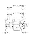
- FIG. 3a shows a plan view of the light guide assembly 16. In the plane visible in this view, the light beams relative to each other still have the angular distribution with which they have entered the light guide assembly 16. A parallelization takes place in these planes through the Umformoptiken 34, which are realized here as a central air lens 33, as parabolic and internally total reflecting interfaces inner recesses 37 and as a parabolic and internally total reflecting external reflectors 39. All forming optics 34 preferably have the same focal point which lies geometrically in the virtual image 44 of the light source 14 arranged in the real focal point. The point at which the light rays 51, 53 of the FIG. 3a is the mirrored at the deflection of the location of the arranged in the real focus light source. All forming optics 34 preferably have the same focal point, which lies geometrically in the virtual image 44 of the light source.
- FIG. 3b shows a front view of the light guide assembly 16 with the light exit surface 20.
- the dashed structure within the light exit surface 20 forms formed therefrom scattering optics. This applies analogously to the wavy course of the light exit surface 20 in FIG. 3a ,
- the semicircular contours represent edges of the coupling optics 16.
- Figure 3c shows a side view of the light guide assembly and the 3d figure shows a section along the plane dd in FIG. 3a
- the round contours 55 are contours of rotation around the Rotation axis 42 in Fig. 2 generated areas.
- FIG. 4 shows an embodiment of an optical waveguide arrangement with a lens as coupling optics 16.
- the light beam forming and curved in space surface in first sectional planes semi-circular edges (eg the edges 55 in FIG. 3b ), whose circle centers lie on an axis 42, on which the light source 14 is arranged.
- the first cutting planes are parallel to the plane of the drawing Fig. 3b , These semicircular edges are z. B. in the FIG. 3b as edges of the coupling optics 16 visible.
- these surfaces have a lenticular contour in second cutting planes.
- the second cutting planes are parallel to the plane of the drawing Figures 2 and 4 , this shows FIG.
- FIG. 2 for the design with the attachment optics and FIG. 4 for the embodiment with the lens, which is there a plano-convex lens.
- the lens whose light exit surface is a light beam forming and curved in space surface.
- the attachment optics whose central light entrance surface 22 is such a light beam forming and curved in space surface.
- the front optics and their lateral reflection surfaces such light bundle forming and curved in space surfaces.
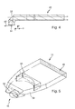
- FIG. 5 shows a perspective view of a lens having a coupling optical system 16 having optical fiber arrangement.
- the parallelization takes place in the radial planes through the lens.
- the further parallelization takes place after the deflection at the flat deflection surface by an inner air lens and by the outer, parabolic contours.
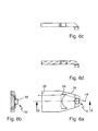
- FIG. 6 shows different views of the subject of the FIG. 5
- FIG. 6a shows a plan view of the light guide assembly 15.
- the light beams relative to each other still have the angular distribution with which they have entered the light guide assembly 16.
- a parallelization takes place in these planes through the Umformoptiken 34, which are realized here as a central air lens 34 and as a parabolic and internally totally reflecting outer reflectors 39.
- All forming optics 34 preferably have the same focal point which lies geometrically in the virtual image 44 of the light source 14 arranged in the real focal point.
- FIG. 6b shows a front view of the light guide assembly with the light exit surface 20.
- the dashed structure within the light exit surface 20 represents molded thereon scattering optics. This applies analogously to the wavy course of the light exit surface 20 in FIG. 6a .
- the semicircular contours 55 in the Fig. 6 b represent edges of the coupling optics 16 (here: the light exit surface of a lens).
- FIG. 6c shows a side view of the light guide assembly and the FIG. 6d shows a section along the plane dd in FIG. 6a ,
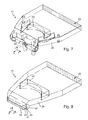
- FIG. 7 shows a perspective view of a light guide assembly, which has a coupling optics with the described intent optical profile, by Rotation of the cross section FIG. 2 is produced.
- This in FIG. 2 shown attachment optics profile has been rotated here about an angle of 180 ° C about an axis parallel to the rotation axis 42.
- FIG. 8 shows an alternative embodiment of a light guide assembly with respect to the FIG. 7 modified attachment optics profile.
- the attachment optics profile of FIG. 8 results by extruding the attachment optics profile FIG. 2 , That is, by rectilinear shifting this intent optical profile along the y-direction.
- the light distribution in the yz plane then differs from the light distribution of the rotated profile FIG. 7 in that the light distribution in the extruded profile is more collimated than in the rotated profile. Strictly speaking, the light distribution in the rotated profile is not collimated at all. It extends over an angular width of 180 ° C, or over the full angular width of the coupled-in light, when the angular width of the light beam is less than 180 °.
- FIG. 9 shows a preferred embodiment of a light guide assembly in a perspective view, in which a serving as Umformoptik 34 inner air lens is realized as a Fresnel lens 40.
- the coupling modules can also be used as a separate component in the light guide arrangement.
- FIG. 10 shows embodiments of separate coupling modules, which are characterized by a stepped light exit surface.
- the light exit surface is stepped in the plane in which the light still propagates radially. This is for example the drawing plane of FIG. 3b
- the FIG. 10b is the light exit surface in the radial plane in which already the first parallelization took place. This is for example the drawing plane of 3d figure ,
- the light exit surface 80 of the coupling optics 16 is divided into a plurality of individual surfaces, which are arranged and shaped so that the propagation directions of light in the first planes are selectively changed when passing through a single surface due to refraction.
- a further embodiment which is the subject of the Fig. 10 a results in a combination of a negative entrance of the light exit surface 80 of the coupling optics 26 formed light entrance surface of the transport and forming optics, the resulting teeth serve as positive locking elements for accurate positioning and mounting the coupling optics in the transport and forming optics.
- FIG. 10b shows a further embodiment of the coupling optics 16 in a sectional view parallel to xz plane.
- the light output surface 80 of the coupling optics 16 is divided into a plurality of individual surfaces.
- the individual surfaces are arranged one above the other like a step.
- the step-like arrangement of the individual surfaces allows a positive fitting of the coupling optics 16 in the z-axis direction and x-axis direction in the transport and forming optics.
- FIG. 11 shows an approximately U-shaped design of the light exit surface, which is produced by juxtaposition of many light exit surfaces of individual optical fiber assemblies.
- a light exit surface can be realized in one piece or in several pieces, wherein in both cases several coupling modules can be used for the coupling of light.
- the FIG. 11 shows in detail a light guide 216, in which the light exit surface 20 is designed U-shaped.
- the view offers a viewer who is located in the emission direction at some distance from the light exit surface and looks at the light exit surface.
- the light guide 216 has a plurality of coupling optics 16.
- the light guide 226 can be thought of as primarily juxtaposed light guide assemblies 15, with individual ones of these light guide assemblies being curved about the x axis to produce the required arcs.
- Each of the coupling-in optics 16 has a light source assigned to it.
- the light guide 216 has support structures 218, which are arranged and arranged to fix the light sources with the circuit carrier and the heat sink to the light guide.
- the coupling optics 16 are distributed along the light exit surface 20 of the light guide, so that a uniform homogeneous illumination of the complicated shaped band-like light exit surface 20 is ensured with almost parallel light. It is understood that other elongated and curved shapes can be realized with it.
- FIG. 12 shows an embodiment in which with one of introduced here Einkoppelmodule, in particular with the vorsatzoptikartigen coupling module and corresponding deflection a curved plate can be homogeneously illuminated.
- the coupling takes place in one of the ways and methods described above.
- a 45 ° C prism rotated about the x-axis is used here in the region near the z-axis. The rotation can be done in several stages, so that the front side is illuminated homogeneously.
- FIG. 12 There are a total of seven such stages.
- the 45 ° C prism which is rotated around the x-axis, not only deflects the light by 90 ° C, but also parallelises it.
- two deflections are required.
- the light propagating radially outward parallel to the yz plane is deflected externally by total reflection at a parabolic section 39 and parallelized in the direction of the z-axis.
- This light must now be deflected at further prism sections by 90 ° C from the z-direction in the x-direction.
- the illustrated grading is needed to produce the desired homogeneity of the illumination of the light exit surface.
- FIG. 13 shows a light guide plate which is partially bent and partially planar.
- a plate can be divided into sections in the FIG. 12 shown plate in combination with the above-explained planar embodiments of transport and forming optics.
- the combination is preferably such that the bent region light sources 14.1 lie in the same plane as the light sources 14.2 for the respective planar region, so that rigid blanks 100 can be used for the bent and planar regions. These are cheaper and can be easier in the production of inventive lighting devices handle as flexible circuit boards.
Landscapes
- Engineering & Computer Science (AREA)
- General Engineering & Computer Science (AREA)
- Physics & Mathematics (AREA)
- Optics & Photonics (AREA)
- General Physics & Mathematics (AREA)
- Microelectronics & Electronic Packaging (AREA)
- Light Guides In General And Applications Therefor (AREA)
- Optical Couplings Of Light Guides (AREA)
- Non-Portable Lighting Devices Or Systems Thereof (AREA)
Abstract
Vorgestellt wird eine Kraftfahrzeugbeleuchtungseinrichtung mit einer Lichtquelle und einer Lichtleiteranordnung, die eine Einkoppeloptik und eine Transport- und Umformoptik aufweist. Die Einkoppeloptik weist eine Lichtbündel formende und im Raum gekrümmte Fläche auf, welche den Öffnungswinkel des Lichtes in zweiten Schnittebenen beim Durchtritt durch diese Fläche reduziert. Die Transport- und Umformoptik weist einen gemeinsamen Brennpunkt aufweisende Umformoptiken auf. Die Lichtquelle ist im gemeinsamen Brennpunkt angeordnet. Die Beleuchtungseinrichtung zeichnet sich insbesondere dadurch aus, dass die Lichtquelle an einer der Lichtaustrittsfläche gegenüberliegenden Seite der Lichtleiteranordnung so angeordnet ist, dass sämtliche Licht der Lichtquelle leitenden Bereiche zwischen der Lichtquelle und der Lichtaustrittsfläche liegen und die eine ebene Umlenkfläche zwischen den im Raum gekrümmten Flächen der Einkoppeloptik und den Umformoptiken angeordnet ist.
Description
- Die vorliegende Erfindung betrifft eine Kraftfahrzeugbeleuchtungseinrichtung nach dem Oberbegriff des Anspruchs 1.
- Eine solche Kraftfahrzeugbeleuchtungseinrichtung wird als per se bekannt vorausgesetzt und weist eine Lichtquelle und eine Lichtleiteranordnung auf, die eine Einkoppeloptik und eine Transport- und Umformoptik aufweist. Die Transport-und Umformoptik weist eine Lichtaustrittsfläche auf, und die Einkoppeloptik ist dazu eingerichtet, ein von der Lichtquelle ausgehendes Lichtbündel umzuformen und zur Transport- und Umformoptik zu richten. Die Einkoppeloptik weist wenigstens eine Lichtbündel formende und im Raum gekrümmte Fläche auf, die in ersten Schnittebenen halbkreisförmige Ränder besitzt, deren Mittelpunkte auf einer Achse liegen, auf der auch die Lichtquelle angeordnet ist, und welche wenigstens eine Fläche in zweiten Schnittebenen eine linsenförmige Kontur aufweist, welche den Öffnungswinkel des Lichtes in diesen zweiten Schnittebenen beim Durchtritt durch diese Fläche reduziert. Die Transport- und Umformoptik weist Umformoptiken auf, mit denen der Öffnungswinkel des sich ursprünglich in den ersten Ebenen ausbreitenden Lichtes vor dem Auftreffen auf die Lichtaustrittsfläche verringert wird.
- Ein Lichtleiter, der diese Merkmale aufweist, ist zum Beispiel aus der
DE 199 25 263 A1 bekannt. - Der bekannte Lichtleiter ist plattenförmig und besitzt ausgedehnte, parallel zueinander liegende Grenzflächen und schmale Seitenflächen, welche die plattenförmigen Grenzflächen miteinander verbinden. Eine der schmalen Seitenflächen dient als Lichtaustrittsfläche, die sich in einem Ausführungsbeispiel über die gesamte Breite der Lichtleiterplatte erstreckt und daher eine langgestreckt rechteckige und damit bandförmige Form besitzt.
- Die Einkoppeloptik ist bei dem bekannten Lichtleiter eine Ausnehmung in der Form eines runden Loches in der Lichtleiterplatte. Die als Lichteintrittsfläche des Lichtleiters dienende Grenzfläche dieser Ausnehmung weist eine nicht-rotationssymmetrische Form auf. Im Inneren der Ausnehmung ist eine Lichtquelle angeordnet.
- Um eine parallele Lichtausbreitung im Lichtleiter in einer zur Lichtaustrittsfläche weisenden Richtung zu erzielen, sieht der bekannte Gegenstand vor, dass ein der bandförmigen Lichtaustrittsseite gegenüberliegender Reflektor in zu den ausgedehnten Plattenflächen parallelen Ebenen parabelförmige Konturen besitzt und senkrecht dazu eine prismenartige Kontur besitzt, welche einfallendes Licht zweimal umlenkt, so dass das umgelenkte Licht in Richtung zur Lichtaustrittsfläche propagiert. Die Lichtquelle ist im Brennpunkt der Parabelkontur angeordnet. Im Ergebnis lenkt der Reflektor das mit einem großen Öffnungswinkel auf ihn einfallende Licht damit als in den genannten Ebenen paralleles Licht auf die dem Reflektor gegenüber liegende bandförmige Lichtaustrittsfläche.
- Ein großer Nachteil dieses Lichtleiters besteht darin, dass direkt in den der Lichtaustrittsfläche zugewandten Halbraum radial abgestrahltes Licht der Lichtquelle nicht auf den ersten Reflektor trifft und daher nicht parallel ausgerichtet wird. Für eine Verwendung in Beleuchtungseinrichtungen von Kraftfahrzeugen, sei es für Scheinwerferlichtfunktionen oder für Signallichtfunktionen, wird jedoch eine vom Inneren des Lichtleiters her mit möglichst parallelem Licht beleuchtete und möglichst homogen (gleichmäßig hell) leuchtende Lichtaustrittsfläche gewünscht. Solches Licht hat z.B. den Vorteil dass es sich durch Streuoptiken in der Lichtaustrittsfläche und/oder durch im Strahlengang des aus der Lichtaustrittsfläche ausgetretenen Lichtes nachfolgende Optiken besonders einfach in regelkonforme Lichtverteilungen verteilen lässt. Aus gestalterischen Gesichtspunkten wird darüber hinaus ein Lichtleiter gewünscht, der eine bandförmige Lichtaustrittsfläche mit einem großem Verhältnis der Länge der Lichtaustrittsfläche zu ihrer Breite besitzt und diese Anforderungen (Homogenität, Parallelität) erfüllt.
- Diese Aufgabe wird mit den Merkmalen des Anspruchs 1 gelöst. Die vorliegende Erfindung unterscheidet sich von dem eingangs genannten Stand der Technik dadurch, dass die Lichtquelle an einer der Lichtaustrittsfläche gegenüberliegenden Seite der Lichtleiteranordnung so angeordnet ist, dass sämtliche Licht der Lichtquelle leitenden Bereiche der Lichtleiteranordnung zwischen der Lichtquelle und der Lichtaustrittsfläche liegen und die Lichtleiteranordnung eine ebene Umlenkfläche aufweist die zwischen den im Raum gekrümmten Flächen der Einkoppeloptik und den Umformoptiken angeordnet ist.
- Beim Stand der Technik liegt die Lichtquelle dagegen innerhalb des Lichtleiters so, dass sie den Lichtleiter in einen zwischen der Lichtquelle und der Lichtaustrittsfläche liegenden ersten Teil und einen zweiten Teil aufteilt, der zwischen einem der Lichtaustrittsfläche abgewandten Ende des Lichtleiters und der Lichtquelle liegt. Aus dieser Lage resultieren die oben genannten Nachteile, weil das Licht, das sich im ersten Teil ausbreitet, nicht oder anders umgeformt wird als das Licht, das sich im zweiten Teil ausbreitet und durch den parabelförmigen Dachkantenreflektor eine Richtungsumkehr und Parallelisierung erfährt.
- Bei der Erfindung tritt dagegen alles Licht der Lichtquelle in das gleiche Lichtleitervolumen ein und kann nachfolgend mit gleichen Umformoptiken umgeformt werden, ohne dass ein Teil des Lichtes dazu eine Richtungsumkehr erfahren muss. Durch die ebene Umlenkfläche wird die Richtung der Lichteinkopplung unabhängig von der Richtung der Lichtaustrittsfläche, so dass die Lage der Lichtquelle mit ihrer Hauptabstrahlrichtung auch bei festgelegter Lage der Lichtaustrittsfläche relativ frei im Raum positioniert werden kann. Der Umstand, dass die Umlenkfläche eine ebene Fläche ist, hat den Vorteil dass das Lichtbündel als Ganzes umgelenkt wird, ohne dass dabei die Winkelverteilung der Lichtstrahlen innerhalb des Bündels verändert wird. Das hat den Vorteil, dass die im Strahlengang nachfolgenden Umformoptiken auch bei einer konstruktiven Anpassung des Umlenkwinkels an andere Bauraumverhältnisse nicht verändert werden müssen.
- Eine bevorzugte Ausgestaltung zeichnet sich dadurch aus, dass die Lichtbündel formende und im Raum gekrümmte Fläche in ersten Schnittebenen halbkreisförmige Ränder besitzt, deren Mittelpunkte auf einer Achse liegen, auf der auch die Lichtquelle angeordnet ist, und welche Flächen in zweiten Schnittebenen eine linsenförmige Kontur aufweisen.
- Bevorzugt ist auch, dass die Einkoppeloptik eine Linse aufweist und die Lichtaustrittsfläche der Linse eine solche Lichtbündel formende und im Raum gekrümmte Flächen ist.
- Bevorzugt ist auch, dass die Einkoppeloptik eine Vorsatzoptik mit einer zentralen Lichteintrittsfläche, seitlichen Lichteintrittsflächen und seitlichen Reflexionsflächen aufweist, wobei die zentrale Lichteintrittsfläche eine solche Lichtbündel formende und im Raum gekrümmte Flächen ist.
- Eine bevorzugte Ausgestaltung zeichnet sich dadurch aus, Kraftfahrzeugbeleuchtungseinrichtung nach einem der vorhergehenden Ansprüche, dadurch gekennzeichnet, dass die Einkoppeloptik eine Vorsatzoptik mit einer zentralen Lichteintrittsfläche, seitlichen Lichteintrittsflächen und seitlichen Reflexionsflächen aufweist, wobei auch die seitliche Reflexionsfläche eine solche Lichtbündel formende und im Raum gekrümmte Fläche ist.
- Bevorzugt ist auch, dass die Einkoppeloptik und die Transport- und Umformoptik einstückig-stoffschlüssig zusammenhängende Bestandteile der Lichtleiteranordnung sind.
- Alternativ ist bevorzugt, dass die Einkoppeloptik und die Transport- und Umformoptik separate Komponenten sind, die zur Lichtleiteranordnung lösbar oder unlösbar zusammengefügt sind.
- Bevorzugt ist auch, dass die Umlenkfläche ein Bestandteil einer separaten Einkoppeloptik-Komponente der Lichtleiteranordnung ist.
- Ferner ist bevorzugt, dass die Umlenkfläche ein Bestandteil einer separaten separaten Transport- und Umformoptik-Komponente der Lichtleiteranordnung ist.
- Bevorzugt ist auch, dass die Umformoptiken eine zentrale Luftlinse aufweisen und/oder als parabelförmige und intern totalreflektierende Grenzflächen innerer Ausnehmungen und/oder als parabelförmige und intern totalreflektierende Außenreflektoren verwirklicht sind.
- Eine weitere bevorzugte Ausgestaltung zeichnet sich dadurch aus, dass sämtliche Umformoptiken den gleichen Brennpunkt besitzen.
- Bevorzugt ist auch, dass die Lichtaustrittsfläche eingeformte Streuoptiken aufweist.
- Bevorzugt ist auch, dass die Form eines räumlichen Vorsatzoptikprofils durch Extrudieren eines flächigen Vorsatzoptikprofils erzeugt wird.
- Ferner ist bevorzugt, dass die Form eines räumlichen Vorsatzoptikprofils durch Rotieren eines flächigen Vorsatzoptikprofils erzeugt wird.
- Eine bevorzugte Ausgestaltung zeichnet sich dadurch aus, Kraftfahrzeugbeleuchtungseinrichtung nach einem der vorhergehenden Ansprüche, dadurch gekennzeichnet, dass eine als Umformoptik dienende innere Luftlinse als Fresnel-Linse verwirklicht ist.
- Weitere Vorteile ergeben sich aus den abhängigen Ansprüchen, der Beschreibung und den beigefügten Figuren.
- Es versteht sich, dass die vorstehend genannten und die nachstehend noch zu erläuternden Merkmale nicht nur in den jeweils angegebenen Kombinationen, sondern auch in anderen Kombinationen oder in Alleinstellung verwendbar sind, ohne den Rahmen der vorliegenden Erfindung zu verlassen.
- Ausführungsbeispiele der Erfindung sind in den Zeichnungen dargestellt und werden in der nachfolgenden Beschreibung näher erläutert. Es zeigen, jeweils in schematischer Form:
-
Figur 1 ein Ausführungsbeispiel einer erfindungsgemäßen Beleuchtungseinrichtung in einem Längsschnitt; -
Figur 2 Figur 2 einen Querschnitt einer Einkoppeloptik 16; -
Figur 3 verschiedene Ansichten einer Lichtleiteranordnung vom Typ der in denFiguren 1 und 2 dargestellten Gegenstände; -
Figur 4 eine Ausgestaltung einer Lichtleiteranordnung mit einer Linse als Einkoppeloptik; -
Figur 5 eine perspektivische Ansicht einer eine Linse als Einkoppeloptik aufweisenden Lichtleiteranordnung; -
Figur 6 verschiedene Ansichten des Gegenstands derFigur 5 ; -
Figur 7 eine perspektivische Ansicht einer Lichtleiteranordnung, die eine Einkoppeloptik mit einem Vorsatzoptikprofil aufweist; -
Figur 8 eine alternative Ausgestaltung einer Lichtleiteranordnung mit einem Vorsatzoptikprofil; -
Figur 9 eine bevorzugte Ausgestaltung einer Lichtleiteranordnung in perspektivischer Ansicht, mit einer Fresnel-Luft-Linse als Umformoptik; -
Figur 10 Ausgestaltungen separater Einkoppelmodule, die sich durch eine gestufte Lichtaustrittsfläche auszeichnen; -
Figur 11 eine abschnittsweise gekrümmte Ausführung der Lichtaustrittsfläche, die durch Aneinanderreihung vieler Lichtaustrittsflächen einzelner Lichtleiteranordnungen erzeugt wird; -
Figur 12 eine Ausgestaltung, die mit einem vorsatzoptikartigen Einkoppelmodul und entsprechender Umlenkung eine gebogene Platte homogen ausleuchtet; und -
Figur 13 eine Lichtleiterplatte, die teilweise gebogen und teilweise eben ist. - Gleiche Bezugszeichen in verschiedenen Figuren bezeichnen dabei jeweils gleiche oder zumindest ihrer Funktion nach vergleichbare Elemente.
-
Figur 1 zeigt eine Kraftfahrzeugbeleuchtungseinrichtung 10 mit einem Gehäuse 11, dessen Lichtaustrittsöffnung von einer transparenten Abdeckscheibe 12 abgedeckt wird. Im Innenraum des Gehäuses befindet sich eine im Gehäuse ortsfest gehaltene Lichtquelle 14 und eine Lichtleiteranordnung 15 mit einer Einkoppeloptik 16 und einer Transport- und Umformoptik 18. Sowohl die Einkoppeloptik 16 als auch die Transport- und Umformoptik 18 bestehen zumindest in ihren Licht der Lichtquelle 18 leitenden Bereichen aus einem transparenten Lichtleitermaterial wie PC, PMMA, Glas, COC oder einem ähnlichen transparenten Material. - Die Transport- und Umformoptik 18 weist an einem Ende eine Lichtaustrittsfläche 20 auf. Die Lichtquelle 14 ist bevorzugt eine Halbleiterlichtquelle, insbesondere eine Leuchtdiode oder eine Anordnung aus mehreren Leuchtdioden. Jede einzelne Leuchtdiode besitzt bevorzugt eine ebene Lichtaustrittsfläche. Die Lichtaustrittsflächen sind bevorzugt rechteckig und weisen eine Kantenlänge von etwa 0,3 mm bis 2 mm auf. Eine Leuchtdiode mit einer solchen Lichtaustrittsfläche kann als Lambertstrahler betrachtet werden, der eine senkrecht zur Lichtaustrittsfläche der Leuchtdiode gerichtete Hauptabstrahlrichtung besitzt und der im Übrigen einen breit geöffneten Lichtkegel in den oberhalb der Lichtaustrittsfläche liegenden Halbraum strahlt. Die Leuchtdioeden können Licht gleicher Farbe erzeugen. In einer anderen Ausgestaltung erzeugen verschiedene Leuchtdioden Licht mit unterschiedlichen Farben, wobei jeweils eine Leuchtdiode Licht einer Farbe erzeugt.
- Die Lichtleiteranordnung 15 ist dazu eingerichtet, dieses breit geöffnete Lichtbündel auseinander laufender Lichtstrahlen in ein Bündel möglichst parallel ausgerichteter Lichtstrahlen 11, 13 umzuformen und diese Lichtstrahlen möglichst gleichmäßig dicht auf die Lichtaustrittsfläche 20 zu verteilen. Das Ziel besteht darin, diese Lichtaustrittsfläche 20 mit parallelem Licht möglichst homogen von innen auszuleuchten. Mit Hilfe von Streuoptiken kann ein solches Lichtbündel leicht in eine regelkonforme Lichtverteilung umgeformt werden, die bei einer bestimmungsgemäßen Verwendung der Beleuchtungseinrichtung als Signalleuchte eines Kraftfahrzeugs eine horizontale Winkelbreite von +/- 20°C und eine vertikale Winkelbreite von +/- 10°C besitzt. Solche Streuoptiken sind in einer Ausgestaltung als in die Lichtaustrittsfläche 20 eingeformte kissenförmige oder zylindermantelabschnittsförmige Strukturen verwirklicht.
- Bei der bestimmungsgemäßen Verwendung ist die x-Richtung, die der Hauptabstrahlrichtung der Lichtaustrittsfläche 20 entspricht, parallel zu einer Vorwärtsfahrtrichtung oder Rückwärtsfahrtrichtung eines Kraftfahrzeugs, während die y-Richtung parallel zur Querachse und die z-Richtung parallel zur Hochachse des Fahrzeugs ausgerichtet ist. Im Folgenden wird zunächst unter Bezug auf die
Figur 2 eine Ausgestaltung einer Einkoppeloptik 16 erläutert. -
Figur 2 zeigt einen Querschnitt einer Einkoppeloptik 16, der in der x-, z-Ebene liegt. Die Einkoppeloptik 16 ist hier eine sogenannte Vorsatzoptik. Sie weist eine zentrale Lichteintrittsfläche 22, seitliche Lichteintrittsflächen 24, 26 und seitliche Reflexionsflächen 28, 30 auf. Die zentrale Lichteintrittsfläche 22 liegt quer zur Hauptabstrahlrichtung einer Lichtquelle 14, und die seitlichen Lichteintrittsflächen liegen eher parallel als quer zu dieser Hauptabstrahlrichtung. Die seitlichen Reflexionsflächen 28, 30 sind so angeordnet, dass sie von Licht beleuchtet werden, das über die seitlichen Lichteintrittsflächen 24, 26 in die Einkoppeloptik 16 eintritt. - Die Form und Anordnung der seitlichen Reflexionsflächen 28, 30 ist darüber hinaus so festgelegt, dass das dort einfallende Licht 27 der Lichtquelle 14 dort interne Totalreflexionen erfährt und das dort reflektierte Licht parallel ausgerichtet und parallel zu dem über die zentrale Lichteintrittsfläche 22 eingetretenen Licht 29 ist. In einer Ausgestaltung sind die Reflexionsflächen mit einer spiegelnden Beschichtung versehen. Bevorzugt ist jedoch eine Verwirklichung ohne eine solche Beschichtung, da solche Beschichtungen aufwändig herzustellen und damit teuer sind. Dies gilt für alle in dieser Anmeldung erwähnten Spiegelflächen. Außerdem treten bei internen Totalreflexionen geringere Lichtverluste auf. Die zentrale Lichteintrittsfläche 22 besitzt eine linsenförmige Kontur und reduziert den Öffnungswinkel des durch diese Fläche hindurchtretenden Lichtes. Die Öffnungswinkelreduzierung erfolgt bevorzugt so, dass das eingekoppelte Licht in der Zeichnungsebene parallel ausgerichtet ist.
- Die folgende Erläuterung bezieht sich wieder auf die
Figur 1 . Die Lichtleiteranordnung weist eine ebene Umlenkfläche 32 auf. Die Transport- und Umformoptik 18 weist Umformoptiken 34 auf. Die Umformoptik 34 ist z. B. eine Luftlinse 33 im Inneren der Transport- und Umformoptik. Im dargestellten Beispiel besitzt die Luftlinse in der Propagationsrichtung des Lichtes eine konkav-plane Form. Unabhängig von ihrer speziellen Ausführung muss die Form die Anforderung erfüllen, dass die Luftlinse das von der Umlenkfläche 32 zur Lichtaustrittsfläche 20 propagierende Licht in eine quer zur Zeichnungsebene liegenden Richtung parallelisiert. Dabei wird unter einer Parallelisierung eine Verkleinerung des Öffnungswinkels verstanden. Es ist bevorzugt, dass die Parallelisierung in einem Ausmaß erfolgt, dass zu einem in dieser Richtung parallelen Lichtbündel führt. - Als Umformoptiken kommen auch reflektierende Flächen von im Inneren der Transport- und Umformoptik liegenden Ausnehmungen in Frage. Solche Flächen sind bevorzugt parabelförmig. Alternativ oder ergänzend kommen auch reflektierende und bevorzugt parabelfömige Außenflächen der Transport- und Umformoptik 18 in Frage. Die Umformoptiken weisen bevorzugt einen gemeinsamen Brennpunkt auf. Die Lichtquelle ist bevorzugt in dem gemeinsamen Brennpunkt angeordnet. In der dargestellten Ausgestaltung sind die Einkoppeloptik 16 und die Transport- und Umformoptik 18 einstückig-stoffschlüssig zusammenhängende Bestandteile der Lichtleiteranordnung 15. Diese Einstückigkeit ist aber nicht obligatorisch. Beide Bestandteile sind in anderen Ausgestaltungen separate Komponenten, die zur Lichtleiteranordnung lösbar oder unlösbar zusammengefügt sind. Die Umlenkfläche kann sowohl als Bestandteil einer separaten Einkoppeloptik-Komponente, als auch als Bestandteil einer separaten Transport- und Umformoptik-Komponente verwirklicht sein.
- Die Lichtquelle 14 ist an einer der Lichtaustrittsflächen 20 gegenüberliegenden Seite, insbesondere an einem der Lichtaustrittsflächen 20 gegenüberliegenden Ende der Lichtleiteranordnung so angeordnet, dass sämtliche Bereiche der Lichtleiteranordnung, die an der Beleuchtung der Lichtaustrittsfläche beteiligtes Licht der Lichtquelle 14 führen, zwischen der Lichtquelle und der Lichtaustrittsfläche liegen. Dies schließt z. B. Ausgestaltungen mit Dachkantenreflektoren aus, wie sie bei dem eingangs genannten Stand der Technik verwendet werden. Die ebene Umlenkfläche liegt zwischen der im Raum gekrümmten Fläche der Einkoppeloptik und den Umformoptiken. Ein Befestigungsstift 36 dient zur Halterung der Lichtleiteranordnung in dem Gehäuse 11. Die Lichtleiteranordnung weist weitere Halterungstrukturen 9 auf.
-
Figur 1 zeigt einen über die zentrale Lichteintrittsfläche der Einkoppeloptik 16 in diese Einkoppeloptik eintretenden Lichtstrahl 38 und einen über eine seitliche Lichteintrittsfläche in die Einkoppeloptik eintretenden Lichtstrahl 40. Beide Lichtstrahlen 38, 40 werden über die ebene Umlenkfläche 32 auf die Lichtaustrittsfläche 20 der Lichtleiteranordnung gerichtet. Die Einkoppeloptik ist insofern dazu eingerichtet, ein von der Lichtquelle ausgehendes Lichtbündel umzuformen und zur Transport- und Umformoptik zu richten. Da die Umlenkfläche 32 eine ebene Fläche ist, lenkt sie das einfallende Bündel als Ganzes um, ohne die Winkelverteilung der einzelnen Strahlen des Bündels in Bezug aufeinander zu ändern. Die reflektierten Strahlen sind also wieder parallele Strahlen. - In einer bevorzugten Ausgestaltung ergeben sich die lichtumformenden Flächen 22, 28 und 30 der Einkoppeloptik im Raum durch Rotieren des in der
Figur 2 sichtbaren Querschnitts um die Rotationsachse 42 in derFig. 1 und Fig. 2 , die durch die Lichtaustrittsfläche der Lichtquelle 14 geht und die senkrecht zur Hauptabstrahlrichtung der Lichtquelle 14 liegt. Die Rotation erfolgt dabei jeweils um 90° in die Zeichnungsebene hinein und um 90° aus der Zeichnungsebene heraus. Eine solche Einkoppeloptik parallelisiert das Licht der Lichtquelle nicht nur in der Zeichnungsebene, sondern in allen möglichen Ebenen, die von der Rotationsachse und einem von der Rotationsachse ausgehenden Radius aufgespannt wird. Solche Ebenen werden im Folgenden auch als Radialebenen bezeichnet. - Der Gegenstand der
Figuren 1 und 2 parallelisiert durch seine lichtbrechende und Licht intern totalreflektierende Wirkung das von der Lichtquelle abgestrahlte und in die Lichtleiteranordnung eingekoppelte Licht in den Radialebenen. -
Figur 3 zeigt verschiedene Ansichten einer Lichtleiteranordnung vom Typ der in denFiguren 1 und 2 dargestellten Lichtleiteranordnung.Figur 3a zeigt eine Draufsicht auf die Lichtleiteranordnung 16. In der in dieser Ansicht sichtbaren Ebene besitzen die Lichtstrahlen relativ zueinander noch die Winkelverteilung, mit der sie in die Lichtleiteranordnung 16 eingetreten sind. Eine Parallelisierung erfolgt in diesen Ebenen durch die Umformoptiken 34, die hier als zentrale Luftlinse 33, als parabelförmige und intern totalreflektierende Grenzflächen innerer Ausnehmungen 37 und als parabelförmige und intern totalreflektierende Außenreflektoren 39 verwirklicht sind. Sämtliche Umformoptiken 34 besitzen bevorzugt den gleichen Brennpunkt, der geometrisch im virtuellen Bild 44 der im reellen Brennpunkt angeordneten Lichtquelle 14 liegt. Der Punkt, in dem sich die Lichtstrahlen 51, 53 derFigur 3a schneiden, ist der an der Umlenkfläche gespiegelte Ort der im reellen Brennpunkt angeordneten Lichtquelle. Sämtliche Umformoptiken 34 besitzen bevorzugt den gleichen Brennpunkt, der geometrisch im virtuellen Bild 44 der Lichtquelle liegt. -
Figur 3b zeigt eine Vorderansicht der Lichtleiteranordnung 16 mit der Lichtaustrittsfläche 20. Die gestrichelte Struktur innerhalb der Lichtaustrittsfläche 20 bildet dort eingeformte Streuoptiken ab. Dies gilt analog für den gewellten Verlauf der Lichtaustrittsfläche 20 inFigur 3a . Die halbkreisförmigen Konturen stellen Kanten der Einkoppeloptik 16 dar.Figur 3c zeigt eine Seitenansicht der Lichtleiteranordnung und dieFigur 3d zeigt einen Schnitt längs der Ebene d-d inFigur 3a . Die runden Konturen 55 sind Konturen der durch Rotation um die Rotationsachse 42 inFig. 2 erzeugten Flächen. -
Figur 4 zeigt eine Ausgestaltung einer Lichtleiteranordnung mit einer Linse als Einkoppeloptik 16. Sowohl für die Ausgestaltung mit der Vorsatzoptik als auch für die Ausgestaltung mit der Linse gilt, dass die lichtbündelformende und im Raum gekrümmte Fläche in ersten Schnittebenen halbkreisförmige Kanten (z.b. die Kanten 55 inFigur 3b ) besitzt, deren Kreismittelpunkte auf einer Achse 42 liegen, auf der auch die Lichtquelle 14 angeordnet ist. Die ersten Schnittebenen sind parallel zur Zeichnungsebene derFig. 3b . Diese halbkreisförmigen Kanten sind z. B. in derFigur 3b als Kanten der Einkoppeloptik 16 sichtbar. Ebenfalls für beide genannten Ausgestaltungen gilt, dass diese Flächen in zweiten Schnittebenen eine linsenförmige Kontur aufweisen. Die zweiten Schnittebenen sind parallel zur Zeichnungsebene derFiguren 2 und4 . Dies zeigtFigur 2 für die Ausgestaltung mit der Vorsatzoptik undFigur 4 für die Ausgestaltung mit der Linse, die dort eine plan-konvexe Linse ist. Im Fall der Linse ist deren Lichtaustrittsfläche eine lichtbündelformende und im Raum gekrümmte Fläche. Im Fall der Vorsatzoptik ist deren zentrale Lichteintrittsfläche 22 eine solche lichtbündelformende und im Raum gekrümmte Fläche. Ferner sind im Fall der Vorsatzoptik auch deren seitliche Reflexionsflächen solche Lichtbündel formenden und im Raum gekrümmten Flächen. -
Figur 5 zeigt eine perspektivische Ansicht einer eine Linse als Einkoppeloptik 16 aufweisenden Lichtleiteranordnung. Die Parallelisierung erfolgt in den Radialebenen durch die Linse. Die weitere Parallelisierung erfolgt nach der Umlenkung an der ebenen Umlenkfläche durch eine innere Luftlinse und durch die äußeren, parabelförmigen Konturen. Auch hier gilt wieder, dass die Umformoptiken den gleichen virtuellen Brennpunkt und den gleichen reellen Brennpunkt besitzen, wobei die Lichtquelle im reellen Brennpunkt angeordnet ist. Der virtuelle Brennpunkt ergibt sich durch Spiegelung des reellen Brennpunkts an der ebenen Umlenkfläche 32. -
Figur 6 zeigt verschiedene Ansichten des Gegenstands derFigur 5 .Figur 6a zeigt eine Draufsicht auf die Lichtleiteranordnung 15. In der in dieser Ansicht sichtbaren Ebene besitzen die Lichtstrahlen relativ zueinander noch die Winkelverteilung, mit der sie in die Lichtleiteranordnung 16 eingetreten sind. Insofern gilt hier auch die Erläuterung zu derFigur 3 . Eine Parallelisierung erfolgt in diesen Ebenen durch die Umformoptiken 34, die hier als zentrale Luftlinse 34 und als parabelförmige und intern totalreflektierende Außenreflektoren 39 verwirklicht sind. Sämtliche Umformoptiken 34 besitzen bevorzugt den gleichen Brennpunkt, der geometrisch im virtuellen Bild 44 der im reellen Brennpunkt angeordneten Lichtquelle 14 liegt. -
Figur 6b zeigt eine Vorderansicht der Lichtleiteranordnung mit der Lichtaustrittsfläche 20. Die gestrichelte Struktur innerhalb der Lichtaustrittsfläche 20 repräsentiert dort eingeformte Streuoptiken. Dies gilt analog für den gewellten Verlauf der Lichtaustrittsfläche 20 inFigur 6a . Die halbkreisförmigen Konturen 55 in derFig. 6 b stellen Kanten der Einkoppeloptik 16 (hier: der Lichtaustrittsfläche einer Linse) dar.Figur 6c zeigt eine Seitenansicht der Lichtleiteranordnung und dieFigur 6d zeigt einen Schnitt längs der Ebene d-d inFigur 6a . -
Figur 7 zeigt eine perspektivische Ansicht einer Lichtleiteranordnung, die eine Einkoppeloptik mit dem beschriebenen Vorsatzoptikprofil aufweist, das durch Rotation des Querschnitts ausFigur 2 erzeugt wird. Das inFigur 2 dargestellt Vorsatzoptikprofil ist hier über einen Winkel von 180°C um eine zur x-Achse parallele Rotationsachse 42 rotiert worden. -
Figur 8 zeigt eine alternative Ausgestaltung einer Lichtleiteranordnung mit einem gegenüber derFigur 7 veränderten Vorsatzoptikprofil. Das Vorsatzoptikprofil derFigur 8 ergibt sich durch Extrudieren des Vorsatzoptikprofils nachFigur 2 , also durch geradlinig erfolgendes Verschieben dieses Vorsatzoptikprofils längs der y-Richtung. Die Lichtverteilung in der y-z-Ebene unterscheidet sich dann von der Lichtverteilung des rotierten Profils nachFigur 7 dadurch, dass die Lichtverteilung beim extrudierten Profil stärker kollimiert ist als beim rotierten Profil. Genau genommen ist die Lichtverteilung beim rotierten Profil gar nicht kollimiert. Sie erstreckt sich über eine Winkelbreite von 180°C, bzw. über die volle Winkelbreite des eingekoppelten Lichts, wenn die Winkelbreite von dessen Lichtbündel kleiner als 180° ist. -
Figur 9 zeigt eine bevorzugte Ausgestaltung einer Lichtleiteranordnung in perspektivischer Ansicht, bei der eine als Umformoptik 34 dienende innere Luftlinse als Fresnel-Linse 40 verwirklicht ist. Für alle Ausgestaltungen gilt, dass die Einkoppelmodule auch als separate Komponente in der Lichtleiteranordnung eingesetzt werden können. -
Figur 10 zeigt Ausgestaltungen separater Einkoppelmodule, die sich durch eine gestufte Lichtaustrittsfläche auszeichnen. Bei derFigur 10a ist die Lichtaustrittsfläche in der Ebene gestuft, in der sich das Licht noch radial ausbreitet. Dies ist zum Beispiel die Zeichnungsebene derFigur 3b . Bei derFigur 10b ist die Lichtaustrittsfläche in der Radialebene gestuft, in der bereits die erste Parallelisierung stattgefunden hat. Dies ist zum Beispiel die Zeichnungsebene derFigur 3d . - Beim Gegenstand der
Figur 10 a ist die Lichtaustrittsfläche 80 der Einkoppeloptik 16 in eine Vielzahl von Einzelflächen unterteilt, die so angeordnet und geformt sind, dass die in den ersten Ebenen liegenden Ausbreitungsrichtungen des Lichts beim Durchtritt durch eine Einzelfläche infolge Brechung gezielt verändert werden. - Dadurch ist es möglich, dass ein Öffnungswinkel der in diesen Ebenen liegenden Ausbreitungsrichtungen des Lichts bereits beim Übergang von der Einkoppeloptik 16 in die Transport- und Umlenkoptik gezielt geändert wird. Die Transport- und Umformoptik kann dann weniger aufwändig gestaltet ausfallen, insbesondere können gegebenenfalls die Umformoptiken 34 entfallen.
- In einer weiteren Ausgestaltung, die sich beim Gegenstand der
Fig. 10 a durch eine Kombination mit einer als Negativ der Lichtaustrittsfläche 80 der Einkoppeloptik 26 geformten Lichteintrittsfläche der Transport- und Umformoptik ergibt, dienen die resultierenden Verzahnungen als Formschlusselemente zur genauen Positionierung und Halterung der Einkoppeloptik in der Transport-und Umformoptik. -
Figur 10b zeigt eine weitere Ausgestaltung der Einkoppeloptik 16 in einer Schnittdarstellung parallel zu x-z-Ebene. In der dargestellten Ausgestaltung ist die Lichtauskoppelfläche 80 der Einkoppeloptik 16 in eine Vielzahl von Einzelflächen unterteilt. Die Einzelflächen sind dabei stufenartig übereinander angeordnet. Die stufenartige Anordnung der Einzelflächen ermöglicht eine formschlüssige Einpassung der Einkoppeloptik 16 in z-Achsenrichtung und x-Achsenrichtung in die Transport- und Umformoptik. -
Figur 11 zeigt eine etwa U-förmige Ausführung der Lichtaustrittsfläche, die durch Aneinanderreihung vieler Lichtaustrittsflächen einzelner Lichtleiteranordnungen erzeugt wird. Allgemein gilt, dass eine solche Lichtaustrittsfläche einstückig oder mehrstückig verwirklicht werden kann, wobei in beiden Fällen mehrere Einkoppelmodule zur Einkopplung von Licht genutzt werden können. DieFigur 11 zeigt im Einzelnen einen Lichtleiter 216, bei dem die Lichtaustrittsfläche 20 u-förmig ausgeführt ist. Die Ansicht bietet sich einem Betrachter, der sich in der Abstrahlrichtung in einiger Entfernung von der Lichtaustrittsfläche entfernt befindet und auf die Lichtaustrittsfläche blickt. Der Lichtleiter 216 weist mehrere Einkoppeloptiken 16 auf. Man kann sich den Lichtleiter 226 als primär nebeneinander angeordnete Lichtleiteranordnungen 15 vorstellen, wobei einzelne dieser Lichtleiteranordnungen um die x-Ache herum gekrümmt sind, um die benötigten Bögen zu erzeugen. Jede der Einkoppeloptiken 16 weist eine ihr zugeordnete Lichtquelle auf. Der Lichtleiter 216 weist Halterungsstrukturen 218 auf, die dazu eingerichtet und angeordnet sind, die Lichtquellen mit dem Schaltungsträger und dem Kühlkörper am Lichtleiter zu befestigen. Die Einkoppeloptiken 16 sind längs der Lichtaustrittsfläche 20 des Lichtleiters verteilt, so dass eine gleichmäßige homogene Beleuchtung der kompliziert geformten bandartigen Lichtaustrittsfläche 20 mit nahezu parallelem Licht gewährleistet ist. Es versteht sich, dass damit auch andere langgestreckte und Krümmungen aufweisende Formen verwirklicht werden können. -
Figur 12 zeigt eine Ausgestaltung, bei der mit einem der hier vorgestellten Einkoppelmodule, insbesondere mit dem vorsatzoptikartigen Einkoppelmodul und entsprechender Umlenkung eine gebogene Platte homogen ausgeleuchtet werden kann. Die Einkopplung erfolgt dabei auf eine der weiter oben beschriebenen Arten und Weisen. Anstelle einer rein ebenen Umlenkfläche wird hier im Bereich nahe der z-Achse ein um die x-Achse rotiertes 45°C-Prisma verwendet. Die Rotation kann man in mehreren Stufen ausführen, damit die Frontseite homogen ausgeleuchtet wird. Beim Gegenstand der -
Figur 12 sind es insgesamt sieben solcher Stufen. Durch das um die x-Achse rotierte 45°C-Prisma wird das Licht nicht nur um 90°C umgelenkt, sondern auch noch parallelisiert. Um den weit von der z-Achse wegliegenden Außenbereich homogen auszuleuchten, benötigt man zwei Umlenkungen. Das nach außen parallel zur y-z-Ebene radial propagierende Licht wird im Außenbereich durch Totalreflexion an einem Parabelabschnitt 39 umgelenkt und in Richtung der z-Achse parallelisiert. Dieses Licht muss nun noch an weiteren Prismenabschnitten um 90°C von der z-Richtung in x-Richtung umgelenkt werden. Die darstellte Stufung wird zur Erzeugung der gewünschten Homogenität der Ausleuchtung der Lichtaustrittsfläche benötigt. -
Figur 13 zeigt eine Lichtleiterplatte, die teilweise gebogen und teilweise eben ist. Eine solche Platte lässt sich durch Teilabschnitte der in derFigur 12 gezeigten Platte in Kombination mit den weiter vorne erläuterten ebenen Ausgestaltungen von Transport- und Umformoptiken erzeugen. Die Kombination erfolgt bevorzugt so, dass die Lichtquellen 14.1 für den gebogenen Bereich in der gleichen Ebene liegen, wie die Lichtquellen 14.2 für den jeweiligen ebenen Breich, sodass man starre Platinen 100 für den gebogenen und den ebenen Bereich verwenden kann. Diese sind preiswerter und lassen sich bei der Herstellung erfindungsgemäßer Beleuchtungseinrichtungen einfacher handhaben als flexible Leiterplatten.
Claims (16)
- Kraftfahrzeugbeleuchtungseinrichtung mit einer Lichtquelle und einer Lichtleiteranordnung, die eine Einkoppeloptik und eine Transport- und Umformoptik aufweist, wobei die Transport- und Umformoptik eine Lichtaustrittsfläche aufweist und die Einkoppeloptik dazu eingerichtet ist, ein von der Lichtquelle ausgehendes Lichtbündel umzuformen und zur Transport- und Umformoptik zu richten, wobei die Einkoppeloptik wenigstens eine Lichtbündel formende und im Raum gekrümmte Fläche aufweist, die eine linsenförmige Kontur aufweist, welche den Öffnungswinkel des Lichtes beim Durchtritt durch diese Fläche reduziert, und wobei die Transport- und Umformoptik einen gemeinsamen Brennpunkt aufweisende Umformoptiken aufweist, und die Lichtquelle im gemeinsamen Brennpunkt angeordnet ist, dadurch gekennzeichnet, dass die Lichtquelle an einer der Lichtaustrittsfläche gegenüberliegenden Seite der Lichtleiteranordnung so angeordnet ist, dass sämtliche Licht der Lichtquelle leitenden Bereiche der Lichtleiteranordnung zwischen der Lichtquelle und der Lichtaustrittsfläche liegen und die Lichtleiteranordnung wenigstens eine ebene Umlenkfläche aufweist, die zwischen den im Raum gekrümmten Flächen der Einkoppeloptik und den Umformoptiken angeordnet ist.
- Kraftfahrzeugbeleuchtungseinrichtung nach Anspruch 1, dadurch gekennzeichnet, dass die Lichtbündel formende und im Raum gekrümmte Fläche in ersten Schnittebenen halbkreisförmige Ränder besitzt, deren Mittelpunkte auf einer Achse liegen, auf der auch die Lichtquelle angeordnet ist, und welche Flächen in zweiten Schnittebenen eine linsenförmige Kontur aufweisen.
- Kraftfahrzeugbeleuchtungseinrichtung nach einem der vorhergehenden Ansprüche, dadurch gekennzeichnet, dass die Einkoppeloptik eine Linse aufweist und die Lichtaustrittsfläche der Linse eine solche Lichtbündel formende und im Raum gekrümmte Flächen ist.
- Kraftfahrzeugbeleuchtungseinrichtung nach einem der vorhergehenden Ansprüche, dadurch gekennzeichnet, dass die Einkoppeloptik eine Vorsatzoptik mit einer zentralen Lichteintrittsfläche, seitlichen Lichteintrittsflächen und seitlichen Reflexionsflächen aufweist, wobei die zentrale Lichteintrittsfläche eine solche Lichtbündel formende und im Raum gekrümmte Flächen ist.
- Kraftfahrzeugbeleuchtungseinrichtung nach einem der vorhergehenden Ansprüche, dadurch gekennzeichnet, dass die Einkoppeloptik eine Vorsatzoptik mit einer zentralen Lichteintrittsfläche, seitlichen Lichteintrittsflächen und seitlichen Reflexionsflächen aufweist, wobei auch die seitliche Reflexionsfläche eine solche Lichtbündel formende und im Raum gekrümmte Fläche ist.
- Kraftfahrzeugbeleuchtungseinrichtung nach einem der vorhergehenden Ansprüche, dadurch gekennzeichnet, dass die Einkoppeloptik und die Transport- und Umformoptik einstückig-stoffschlüssig zusammenhängende Bestandteile der Lichtleiteranordnung sind.
- Kraftfahrzeugbeleuchtungseinrichtung nach einem der vorhergehenden Ansprüche, dadurch gekennzeichnet, dass die Einkoppeloptik und die Transport- und Umformoptik separate Komponenten sind, die zur Lichtleiteranordnung lösbar oder unlösbar zusammengefügt sind.
- Kraftfahrzeugbeleuchtungseinrichtung nach einem der vorhergehenden Ansprüche, dadurch gekennzeichnet, dass die Umlenkfläche ein Bestandteil einer separaten Einkoppeloptik-Komponente der Lichtleiteranordnung ist.
- Kraftfahrzeugbeleuchtungseinrichtung nach einem der vorhergehenden Ansprüche, dadurch gekennzeichnet, dass die Umlenkfläche ein Bestandteil einer separaten Transport- und Umformoptik-Komponente der Lichtleiteranordnung ist.
- Kraftfahrzeugbeleuchtungseinrichtung nach einem der vorhergehenden Ansprüche, dadurch gekennzeichnet, dass die Umformoptiken eine zentrale Luftlinse aufweisen und/oder als parabelförmige und intern totalreflektierende Grenzflächen innerer Ausnehmungen und/oder als parabelförmige und intern totalreflektierende Außenreflektoren verwirklicht sind.
- Kraftfahrzeugbeleuchtungseinrichtung nach einem der vorhergehenden Ansprüche, dadurch gekennzeichnet, dass sämtliche Umformoptiken den gleichen Brennpunkt besitzen.
- Kraftfahrzeugbeleuchtungseinrichtung nach einem der vorhergehenden Ansprüche, dadurch gekennzeichnet, dass die Lichtaustrittsfläche eingeformte Streuoptiken aufweist.
- Kraftfahrzeugbeleuchtungseinrichtung nach einem der vorhergehenden Ansprüche, dadurch gekennzeichnet, dass die Form eines räumlichen Vorsatzoptikprofils durch Extrudieren eines flächigen Vorsatzoptikprofils erzeugt wird.
- Kraftfahrzeugbeleuchtungseinrichtung nach einem der vorhergehenden Ansprüche, dadurch gekennzeichnet, dass die Form eines räumlichen Vorsatzoptikprofils durch Rotieren eines flächigen Vorsatzoptikprofils erzeugt wird.
- Kraftfahrzeugbeleuchtungseinrichtung nach einem der vorhergehenden Ansprüche, dadurch gekennzeichnet, dass eine als Umformoptik 34 dienende innere Luftlinse als Fresnel-Linse verwirklicht ist.
- Kraftfahrzeugbeleuchtungseinrichtung nach einem der vorhergehenden Ansprüche, dadurch gekennzeichnet, dass die Lichtquelle mehrere Leuchtdioden aufweist, die gleichfarbiges Licht oder Licht unterschiedlicher Farbe erzeugen, wobei eine einzelne Leuchtdiode jeweils einfarbiges Licht erzeugt.
Applications Claiming Priority (1)
| Application Number | Priority Date | Filing Date | Title |
|---|---|---|---|
| DE102013212352.3A DE102013212352A1 (de) | 2013-06-26 | 2013-06-26 | Kraftfahrzeugbeleuchtungseinrichtung mit einer Einkoppeloptik und einer Transport- und Umformoptik |
Publications (1)
| Publication Number | Publication Date |
|---|---|
| EP2818791A1 true EP2818791A1 (de) | 2014-12-31 |
Family
ID=50828793
Family Applications (1)
| Application Number | Title | Priority Date | Filing Date |
|---|---|---|---|
| EP14170653.1A Withdrawn EP2818791A1 (de) | 2013-06-26 | 2014-05-30 | Kraftfahrzeugbeleuchtungseinrichtung mit einer Einkoppeloptik und einer Transport- und Umformoptik |
Country Status (4)
| Country | Link |
|---|---|
| US (1) | US20150003094A1 (de) |
| EP (1) | EP2818791A1 (de) |
| CN (1) | CN104251443A (de) |
| DE (1) | DE102013212352A1 (de) |
Cited By (15)
| Publication number | Priority date | Publication date | Assignee | Title |
|---|---|---|---|---|
| DE202015005050U1 (de) | 2015-07-14 | 2016-10-17 | Automotive Lighting Reutlingen Gmbh | Lichtleiter |
| EP3121510A1 (de) * | 2015-07-22 | 2017-01-25 | Automotive Lighting Reutlingen GmbH | Vorsatzoptik |
| ITUA20162156A1 (it) * | 2016-03-31 | 2017-10-01 | Automotive Lighting Italia Spa | Fanale automobilistico |
| FR3050010A1 (fr) * | 2016-04-11 | 2017-10-13 | Valeo Vision | Module d'emission de lumiere compact, dispositif et projecteur associes pour vehicule automobile |
| EP2716962A3 (de) * | 2012-10-03 | 2018-02-14 | Koito Manufacturing Co., Ltd. | Fahrzeugleuchte |
| WO2018162037A1 (en) * | 2017-03-07 | 2018-09-13 | HELLA GmbH & Co. KGaA | Lighting device for vehicles |
| EP3396238A1 (de) * | 2017-04-27 | 2018-10-31 | Valeo Lighting Hubei Technical Center Co Ltd | Leuchtvorrichtung und fahrzeugleuchtenanordnung |
| EP3502551A1 (de) * | 2017-12-19 | 2019-06-26 | Automotive Lighting Italia S.p.A. | Beleuchtungsvorrichtung für fahrzeuge |
| EP3578876A1 (de) * | 2018-06-04 | 2019-12-11 | Stanley Electric Co., Ltd. | Fahrzeuglampe |
| EP3578877A1 (de) * | 2018-06-04 | 2019-12-11 | Stanley Electric Co., Ltd. | Fahrzeuglampe |
| EP3480514A4 (de) * | 2016-06-29 | 2020-01-01 | Koito Manufacturing Co., Ltd. | Fahrzeuglampe |
| EP3712492A1 (de) * | 2019-03-22 | 2020-09-23 | Stanley Electric Co., Ltd. | Beleuchtungsvorrichtung für fahrzeug siglalleuchte |
| IT202100008909A1 (it) * | 2021-04-09 | 2022-10-09 | Marelli Automotive Lighting Italy S P A Con Socio Unico | Dispositivo di illuminazione per veicoli, in particolare a led |
| WO2023072988A1 (en) * | 2021-10-29 | 2023-05-04 | Valeo Vision | Light guide blade for a motor vehicle |
| DE102019106221B4 (de) | 2019-03-12 | 2026-05-21 | HELLA GmbH & Co. KGaA | Beleuchtungsvorrichtung für Fahrzeuge |
Families Citing this family (34)
| Publication number | Priority date | Publication date | Assignee | Title |
|---|---|---|---|---|
| FR2998678B1 (fr) * | 2012-11-29 | 2016-01-08 | Valeo Vision | Guide de lumiere pour un dispositif optique, notamment d'eclairage et/ou de signalisation |
| FR3015005B1 (fr) * | 2013-12-13 | 2018-12-07 | Valeo Systemes Thermiques | Dispositif lumineux |
| TWI607181B (zh) * | 2015-07-06 | 2017-12-01 | 隆達電子股份有限公司 | 導光柱與使用其的車用燈具 |
| DE102015225722A1 (de) | 2015-12-17 | 2017-06-22 | Continental Automotive Gmbh | Touchscreen mit einer haptischen Rückmeldevorrichtung |
| AT518109B1 (de) * | 2016-01-14 | 2017-11-15 | Zkw Group Gmbh | Beleuchtungseinheit für einen Kraftfahrzeugscheinwerfer zum Erzeugen eines Lichtbündels mit Hell-Dunkel-Grenze |
| US20200292143A1 (en) * | 2016-03-21 | 2020-09-17 | Lumileds Llc | Lighting arrangement |
| JP6838327B2 (ja) * | 2016-09-13 | 2021-03-03 | 市光工業株式会社 | 車両用光学部材および車両用光学部材を備える車両用灯具 |
| JP6720809B2 (ja) * | 2016-09-29 | 2020-07-08 | オムロン株式会社 | 導光部材、導光部材ユニットおよび照明装置 |
| DE102016120133A1 (de) | 2016-10-21 | 2018-04-26 | Automotive Lighting Reutlingen Gmbh | Lichtmodul eines Kraftfahrzeugscheinwerfers und Scheinwerfer mit einem solchen Lichtmodul |
| CN107975693A (zh) * | 2016-10-24 | 2018-05-01 | 常州星宇车灯股份有限公司 | 一种新型led灯导光结构 |
| CN106524031A (zh) * | 2016-10-31 | 2017-03-22 | 马瑞利汽车零部件(芜湖)有限公司 | 双色车灯光导 |
| IT201600121517A1 (it) * | 2016-11-30 | 2018-05-30 | Automotive Lighting Italia Spa | Fanale automobilistico comprendente una porzione di emissione luminosa ad effetto opalescente |
| FR3062453B1 (fr) * | 2017-01-27 | 2019-03-29 | Peugeot Citroen Automobiles Sa | Dispositif d’eclairage a guide de lumiere monte sur une piece de support integrant un ecran transparent d’agrandissement |
| FR3062451B1 (fr) * | 2017-01-27 | 2019-03-29 | Peugeot Citroen Automobiles Sa | Dispositif d’eclairage a masque a motifs en pointe de diamant |
| FR3063797B1 (fr) * | 2017-03-07 | 2019-03-22 | Peugeot Citroen Automobiles Sa | Dispositif d’eclairage a positionnements simplifies et precis des sources de lumiere et guides de lumiere |
| DE102017105838B4 (de) * | 2017-03-17 | 2026-01-08 | Automotive Lighting Reutlingen Gmbh | Beleuchtungseinrichtung eines Kraftfahrzeugs mit einer Lichtleiteranordnung |
| CN107131462A (zh) * | 2017-05-17 | 2017-09-05 | 上海小糸车灯有限公司 | 一种车灯及其聚光装置、聚光器 |
| CN107806615A (zh) * | 2017-10-31 | 2018-03-16 | 马瑞利汽车零部件(芜湖)有限公司 | 不均匀壁厚的边缘发光厚壁件模块 |
| CN113639247B (zh) * | 2017-11-20 | 2023-11-28 | 市光法雷奥(佛山)汽车照明系统有限公司 | 光导构件、发光组件、照明装置和车辆 |
| CN107975755A (zh) * | 2017-12-26 | 2018-05-01 | 上海小糸车灯有限公司 | 车灯用大曲率光导及车灯用光学模组 |
| CN108037580B (zh) * | 2018-01-09 | 2025-03-07 | 中山日荣塑料电子制品有限公司 | 一种导光式显微镜 |
| US10705289B2 (en) * | 2018-06-14 | 2020-07-07 | Sharp Kabushiki Kaisha | Lighting device and display device |
| JP2020004483A (ja) * | 2018-06-25 | 2020-01-09 | 株式会社小糸製作所 | 車両用灯具 |
| FR3084727B1 (fr) * | 2018-08-03 | 2022-01-21 | Valeo Vision Belgique | Dispositif lumineux pour vehicule automobile |
| TWI682222B (zh) | 2018-09-27 | 2020-01-11 | 緯創資通股份有限公司 | 導光裝置及具有發光功能的指示設備 |
| DE102018127610A1 (de) * | 2018-11-06 | 2020-05-07 | HELLA GmbH & Co. KGaA | Verfahren zur Herstellung eines Optikbausteins, Optikbaustein sowie Abbildungseinheit |
| US11408575B2 (en) * | 2018-12-21 | 2022-08-09 | Zkw Group Gmbh | Illumination device for a motor vehicle headlight, and motor vehicle headlight |
| CN109519873A (zh) * | 2018-12-28 | 2019-03-26 | 马瑞利汽车零部件(芜湖)有限公司 | 适用于多造型信号灯的光学系统 |
| KR102843635B1 (ko) | 2019-07-03 | 2025-08-07 | 엘지이노텍 주식회사 | 조명 모듈, 조명 장치 및 램프 |
| CH717330B1 (de) | 2020-07-27 | 2021-10-29 | Polycontact Ag | Optik für eine Beleuchtungseinrichtung und Beleuchtungseinrichtung. |
| DE102020126944A1 (de) | 2020-09-03 | 2022-03-03 | HELLA GmbH & Co. KGaA | Verfahren zum Herstellen eines Flachlichtleiters und Beleuchtungsvorrichtung |
| US12117138B2 (en) * | 2022-06-14 | 2024-10-15 | Tyri International, Inc. | Beamshaping waveguide for headlights |
| US20250264201A1 (en) * | 2024-02-15 | 2025-08-21 | Tyri International Inc. | Vehicle Headlamp for High Mount Applications |
| KR20250144128A (ko) * | 2024-03-26 | 2025-10-10 | 현대모비스 주식회사 | 차량용 램프 |
Citations (6)
| Publication number | Priority date | Publication date | Assignee | Title |
|---|---|---|---|---|
| DE19925263C1 (de) | 1999-06-01 | 2000-10-12 | Siemens Ag | Verfahren zum Betreiben eines Mobilfunksystems sowie dafür geeignete Basisstation |
| US20060171159A1 (en) * | 2003-04-04 | 2006-08-03 | Daniel Anderlini | Rear light, particularly a stop light for a motor vehicle |
| US20070019429A1 (en) * | 2005-07-21 | 2007-01-25 | Valeo Vision | Lighting or indicator device, in particular for motor vehicles |
| EP1881265A1 (de) * | 2006-07-21 | 2008-01-23 | Valeo Vision | Beleuchtungseinrichtung mit einer Lichtleiterplatte, die eine kreisbogenförmige, rückstrahlende Reflexionsfläche aufweist |
| EP1895228A1 (de) * | 2006-09-01 | 2008-03-05 | Valeo Vision | Vorrichtung zur Beleuchtung oder Signalisierung vom Typ Hochleistungs-Lichtwellenleiter für Kraftfahrzeuge |
| EP2568320A2 (de) * | 2011-09-07 | 2013-03-13 | Koito Manufacturing Co., Ltd. | Fahrzeugleuchte |
-
2013
- 2013-06-26 DE DE102013212352.3A patent/DE102013212352A1/de active Granted
-
2014
- 2014-05-30 EP EP14170653.1A patent/EP2818791A1/de not_active Withdrawn
- 2014-06-24 CN CN201410286142.9A patent/CN104251443A/zh active Pending
- 2014-06-24 US US14/312,768 patent/US20150003094A1/en not_active Abandoned
Patent Citations (6)
| Publication number | Priority date | Publication date | Assignee | Title |
|---|---|---|---|---|
| DE19925263C1 (de) | 1999-06-01 | 2000-10-12 | Siemens Ag | Verfahren zum Betreiben eines Mobilfunksystems sowie dafür geeignete Basisstation |
| US20060171159A1 (en) * | 2003-04-04 | 2006-08-03 | Daniel Anderlini | Rear light, particularly a stop light for a motor vehicle |
| US20070019429A1 (en) * | 2005-07-21 | 2007-01-25 | Valeo Vision | Lighting or indicator device, in particular for motor vehicles |
| EP1881265A1 (de) * | 2006-07-21 | 2008-01-23 | Valeo Vision | Beleuchtungseinrichtung mit einer Lichtleiterplatte, die eine kreisbogenförmige, rückstrahlende Reflexionsfläche aufweist |
| EP1895228A1 (de) * | 2006-09-01 | 2008-03-05 | Valeo Vision | Vorrichtung zur Beleuchtung oder Signalisierung vom Typ Hochleistungs-Lichtwellenleiter für Kraftfahrzeuge |
| EP2568320A2 (de) * | 2011-09-07 | 2013-03-13 | Koito Manufacturing Co., Ltd. | Fahrzeugleuchte |
Cited By (21)
| Publication number | Priority date | Publication date | Assignee | Title |
|---|---|---|---|---|
| EP2716962A3 (de) * | 2012-10-03 | 2018-02-14 | Koito Manufacturing Co., Ltd. | Fahrzeugleuchte |
| DE202015005050U1 (de) | 2015-07-14 | 2016-10-17 | Automotive Lighting Reutlingen Gmbh | Lichtleiter |
| EP3121510A1 (de) * | 2015-07-22 | 2017-01-25 | Automotive Lighting Reutlingen GmbH | Vorsatzoptik |
| ITUA20162156A1 (it) * | 2016-03-31 | 2017-10-01 | Automotive Lighting Italia Spa | Fanale automobilistico |
| FR3050010A1 (fr) * | 2016-04-11 | 2017-10-13 | Valeo Vision | Module d'emission de lumiere compact, dispositif et projecteur associes pour vehicule automobile |
| US11079087B2 (en) | 2016-06-29 | 2021-08-03 | Koito Manufacturing Co., Ltd. | Vehicle lamp |
| EP3480514A4 (de) * | 2016-06-29 | 2020-01-01 | Koito Manufacturing Co., Ltd. | Fahrzeuglampe |
| US10908345B2 (en) | 2017-03-07 | 2021-02-02 | HELLA GmbH & Co. KGaA | Lighting device for vehicles |
| WO2018162037A1 (en) * | 2017-03-07 | 2018-09-13 | HELLA GmbH & Co. KGaA | Lighting device for vehicles |
| EP3396238A1 (de) * | 2017-04-27 | 2018-10-31 | Valeo Lighting Hubei Technical Center Co Ltd | Leuchtvorrichtung und fahrzeugleuchtenanordnung |
| US10480743B2 (en) | 2017-04-27 | 2019-11-19 | Valeo Lighting Hubei Technical Center Co. Ltd | Light beam adjusting device and vehicle lamp assembly |
| EP3502551A1 (de) * | 2017-12-19 | 2019-06-26 | Automotive Lighting Italia S.p.A. | Beleuchtungsvorrichtung für fahrzeuge |
| EP3578877A1 (de) * | 2018-06-04 | 2019-12-11 | Stanley Electric Co., Ltd. | Fahrzeuglampe |
| US10837618B2 (en) | 2018-06-04 | 2020-11-17 | Stanley Electric Co., Ltd. | Vehicular lamp |
| EP3578876A1 (de) * | 2018-06-04 | 2019-12-11 | Stanley Electric Co., Ltd. | Fahrzeuglampe |
| DE102019106221B4 (de) | 2019-03-12 | 2026-05-21 | HELLA GmbH & Co. KGaA | Beleuchtungsvorrichtung für Fahrzeuge |
| EP3712492A1 (de) * | 2019-03-22 | 2020-09-23 | Stanley Electric Co., Ltd. | Beleuchtungsvorrichtung für fahrzeug siglalleuchte |
| US11041601B2 (en) | 2019-03-22 | 2021-06-22 | Stanley Electric Co., Ltd. | Lighting tool for vehicle |
| IT202100008909A1 (it) * | 2021-04-09 | 2022-10-09 | Marelli Automotive Lighting Italy S P A Con Socio Unico | Dispositivo di illuminazione per veicoli, in particolare a led |
| EP4071402A1 (de) * | 2021-04-09 | 2022-10-12 | Marelli Automotive Lighting Italy S.p.A. Con Socio Unico | Beleuchtungseinrichtung für fahrzeuge, insbesondere mit leds |
| WO2023072988A1 (en) * | 2021-10-29 | 2023-05-04 | Valeo Vision | Light guide blade for a motor vehicle |
Also Published As
| Publication number | Publication date |
|---|---|
| DE102013212352A1 (de) | 2014-12-31 |
| CN104251443A (zh) | 2014-12-31 |
| US20150003094A1 (en) | 2015-01-01 |
Similar Documents
| Publication | Publication Date | Title |
|---|---|---|
| DE102013212352A1 (de) | Kraftfahrzeugbeleuchtungseinrichtung mit einer Einkoppeloptik und einer Transport- und Umformoptik | |
| EP2587120B1 (de) | Lichtleiterelement und Kraftfahrzeugleuchte mit einem Lichtleiterelement | |
| EP2889529B1 (de) | Kraftfahrzeugleuchte mit einem linien- oder flächenhaften Erscheinungsbild | |
| DE102013212355B4 (de) | Kraftfahrzeugbeleuchtungseinrichtung mit einem eine Einkoppeloptik und eine Transport- und Umformoptik aufweisenden Lichtleiter | |
| DE102012224079B4 (de) | Lichtleiter mit einer bandförmigen Lichtaustrittsfläche | |
| DE102011089575B3 (de) | Beleuchtungseinrichtung für ein Kraftfahrzeug mit einem gestuften Lichtleiter | |
| DE102013212353B4 (de) | Kraftfahrzeugbeleuchtungseinrichtung mit einer eine Einkoppeloptik und eine Transport- und Umformoptik aufweisenden Lichtleiteranordnung | |
| EP3080513B1 (de) | Kraftfahrzeugbeleuchtungseinrichtung | |
| DE112017004923B4 (de) | Lichtführungselement, Lichtführungseinheit und Beleuchtungsvorrichtung | |
| DE102022113052A1 (de) | Beleuchtungsvorrichtung für ein Kraftfahrzeug | |
| DE102016100207A1 (de) | Signalleuchte | |
| DE102011089481A1 (de) | Kraftfahrzeugbeleuchtungseinrichtung mit einer langen und flachen leuchtenden Fläche | |
| DE102017114476B4 (de) | Beleuchtungseinrichtung eines Kraftfahrzeugs | |
| EP2618045A1 (de) | Beleuchtungseinrichtung für ein Kraftfahrzeug | |
| DE102010025208A1 (de) | Kraftfahrzeugbeleuchtungseinrichtung mit einem langgestreckten Lichtleiter | |
| EP2500753B1 (de) | Lichtleiter mit direkt Licht auskoppelnden Auskoppelelementen | |
| EP2372235A2 (de) | Fahrzeugleuchte mit einer Lichtleiter-Vorsatzoptik | |
| EP2927572B1 (de) | Kraftfahrzeugleuchte mit wischeffekt | |
| DE102015213827A1 (de) | Vorsatzoptik für eine Signalleuchte einer Kraftfahrzeugbeleuchtungseinrichtung | |
| EP3121510A1 (de) | Vorsatzoptik | |
| EP2490052B1 (de) | Beleuchtungseinrichtung eines Kraftfahrzeugs | |
| DE102015204735B4 (de) | Lichtleiterelement einer Kraftfahrzeug-Beleuchtungseinrichtung und Kraftfahrzeug-Beleuchtungseinrichtung mit einem solchen Lichtleiterelement | |
| EP3812653B1 (de) | Signalleuchte mit einem lichtleiter | |
| DE102012215124B4 (de) | Beleuchtungseinrichtung mit mehreren Lichtquellen und Lichtleitkörpern sowie einem Reflektor | |
| DE102015207960A1 (de) | Plattenförmiges Lichtleiterelement zum Einsatz in einer Beleuchtungseinrichtung eines Kraftfahrzeugs und Beleuchtungseinrichtung mit einem solchen Lichtleiterelement |
Legal Events
| Date | Code | Title | Description |
|---|---|---|---|
| PUAI | Public reference made under article 153(3) epc to a published international application that has entered the european phase |
Free format text: ORIGINAL CODE: 0009012 |
|
| 17P | Request for examination filed |
Effective date: 20140530 |
|
| AK | Designated contracting states |
Kind code of ref document: A1 Designated state(s): AL AT BE BG CH CY CZ DE DK EE ES FI FR GB GR HR HU IE IS IT LI LT LU LV MC MK MT NL NO PL PT RO RS SE SI SK SM TR |
|
| AX | Request for extension of the european patent |
Extension state: BA ME |
|
| STAA | Information on the status of an ep patent application or granted ep patent |
Free format text: STATUS: THE APPLICATION IS DEEMED TO BE WITHDRAWN |
|
| 18D | Application deemed to be withdrawn |
Effective date: 20150701 |