EP2818621A1 - Composite section bar for doors, windows and shutters, and process for manufacture it - Google Patents
Composite section bar for doors, windows and shutters, and process for manufacture it Download PDFInfo
- Publication number
- EP2818621A1 EP2818621A1 EP14173738.7A EP14173738A EP2818621A1 EP 2818621 A1 EP2818621 A1 EP 2818621A1 EP 14173738 A EP14173738 A EP 14173738A EP 2818621 A1 EP2818621 A1 EP 2818621A1
- Authority
- EP
- European Patent Office
- Prior art keywords
- section bar
- undercut
- glass
- eccentric
- wooden
- Prior art date
- Legal status (The legal status is an assumption and is not a legal conclusion. Google has not performed a legal analysis and makes no representation as to the accuracy of the status listed.)
- Granted
Links
Images


Classifications
-
- E—FIXED CONSTRUCTIONS
- E06—DOORS, WINDOWS, SHUTTERS, OR ROLLER BLINDS IN GENERAL; LADDERS
- E06B—FIXED OR MOVABLE CLOSURES FOR OPENINGS IN BUILDINGS, VEHICLES, FENCES OR LIKE ENCLOSURES IN GENERAL, e.g. DOORS, WINDOWS, BLINDS, GATES
- E06B3/00—Window sashes, door leaves, or like elements for closing wall or like openings; Layout of fixed or moving closures, e.g. windows in wall or like openings; Features of rigidly-mounted outer frames relating to the mounting of wing frames
- E06B3/04—Wing frames not characterised by the manner of movement
- E06B3/263—Frames with special provision for insulation
- E06B3/26341—Frames with special provision for insulation comprising only one metal frame member combined with an insulating frame member
-
- E—FIXED CONSTRUCTIONS
- E06—DOORS, WINDOWS, SHUTTERS, OR ROLLER BLINDS IN GENERAL; LADDERS
- E06B—FIXED OR MOVABLE CLOSURES FOR OPENINGS IN BUILDINGS, VEHICLES, FENCES OR LIKE ENCLOSURES IN GENERAL, e.g. DOORS, WINDOWS, BLINDS, GATES
- E06B3/00—Window sashes, door leaves, or like elements for closing wall or like openings; Layout of fixed or moving closures, e.g. windows in wall or like openings; Features of rigidly-mounted outer frames relating to the mounting of wing frames
- E06B3/30—Coverings, e.g. protecting against weather, for decorative purposes
- E06B3/301—Coverings, e.g. protecting against weather, for decorative purposes consisting of prefabricated profiled members or glass
- E06B3/303—Covering metal or plastic frames with wooden profiled members
-
- E—FIXED CONSTRUCTIONS
- E06—DOORS, WINDOWS, SHUTTERS, OR ROLLER BLINDS IN GENERAL; LADDERS
- E06B—FIXED OR MOVABLE CLOSURES FOR OPENINGS IN BUILDINGS, VEHICLES, FENCES OR LIKE ENCLOSURES IN GENERAL, e.g. DOORS, WINDOWS, BLINDS, GATES
- E06B3/00—Window sashes, door leaves, or like elements for closing wall or like openings; Layout of fixed or moving closures, e.g. windows in wall or like openings; Features of rigidly-mounted outer frames relating to the mounting of wing frames
- E06B3/54—Fixing of glass panes or like plates
- E06B3/5481—Fixing of glass panes or like plates by means of discrete fixing elements, e.g. glazing clips, glaziers points
-
- E—FIXED CONSTRUCTIONS
- E06—DOORS, WINDOWS, SHUTTERS, OR ROLLER BLINDS IN GENERAL; LADDERS
- E06B—FIXED OR MOVABLE CLOSURES FOR OPENINGS IN BUILDINGS, VEHICLES, FENCES OR LIKE ENCLOSURES IN GENERAL, e.g. DOORS, WINDOWS, BLINDS, GATES
- E06B3/00—Window sashes, door leaves, or like elements for closing wall or like openings; Layout of fixed or moving closures, e.g. windows in wall or like openings; Features of rigidly-mounted outer frames relating to the mounting of wing frames
- E06B3/54—Fixing of glass panes or like plates
- E06B3/58—Fixing of glass panes or like plates by means of borders, cleats, or the like
- E06B3/5878—Fixing of glass panes or like plates by means of borders, cleats, or the like the borders being pre-assembled in a frame-like manner on the pane or on the frame before the pane is fitted to the frame
Definitions
- the present invention relates to a structural section bar that is suitable for manufacturing closures, such as doors, windows and shutters of the mixed type, or rather with the surface facing outwards in aluminium alloy, or other metal material, and the surface facing inwards in wood, or other decorative material, as well as the particular method and relative device which allows the different materials to be formed into a single element with the arrangement in between them of a further section bar element that, for its shape and type of material, has the task of absorbing possible different heat-expansions and of improving the acoustic and thermal performances of the product.
- the purpose of the present invention is to avoid said drawbacks.
- One preferred embodiment of the invention comprises an assembly of section bars for closures such as doors, windows and shutters that are each obtained by connecting three elements made of different material with a relative method and device for simultaneously forming them, obtaining the holding of the glass characterised by comprising:
- Another aspect of the invention concerns a process having the features according to claim 7.
- Another aspect of the invention concerns a method for forming a single composite section bar, which is obtained by connecting the aforementioned three elements made of different material, which comprises a device formed by a central cylindrical body that is equipped, at the ends and in the middle, with three eccentric shaped heads as well as with a further figure having a suitable thickness and the shape of a cam, with one side that is longer than the other one in the perpendicular position, arranged between one of the end heads and that in the central position.
- Another aspect of the invention concerns a process for joining the three elements made of different material consisting of approaching the section bar made of synthetic material to the metal section bar, resting the sheet of glass against the suitable wing for supporting the metal section bar, inserting the cylindrical devices provided with eccentric and cam-shaped heads through the slots of the synthetic section bar, resting the decorative element on said heads using its undercut seat as a guide, acting on the long side of the cam exerting a rotation by 90°, along the axis of the cylindrical body of the device, which thus simultaneously engages with interference, the eccentric heads each one in each seat of the three different elements and at the same time the other side of the cam will be positioned on the edge of the glass sheet keeping it in its seat.
- the invention concerns an assembly of section bars for doors, windows and shutters that is characterised in that it comprises:
- the section bar 12 can be made for example in polyvinyl chloride (PVC) or other material.
- PVC polyvinyl chloride
- the coupling devices (18) can be made for example through injection moulding in a suitable plastic material.
- the metal section bar (7) in the undercut seat oriented towards the interior (9) receives, resting adjacently against it, the element in synthetic material (12) provided with through slots (13) that are arranged for example at a constant pitch for its length.
- Such slots (13) in their formation and in their location make it possible to free the element (12) from the ribs and cavities (14 e 14') thus creating a single undercut seat (15).
- the synthetic section bar (12) can be fixed also only temporarily, by hooking with the metal one (7) with pressure wings or other mechanical joints.
- the coupling device (18) passes through the slots 13 until the eccentric head is positioned (20) in the undercut (9) of the metal section bar (7) and the middle eccentric (20') in the single undercut (15) of the synthetic section bar (12) created by the slot (13).
- the cam figure (21) acts, in addition to as a spacer for its thickness, also as an internal holding element for the sheet of glass (11) with its short side (23) pressing on the edge of such an element.
- the shaped wooden element (16) in its undercut seat (17) receives the other eccentric head (20") of the device (18).
- the sheet of glass (11) is positioned and rested on the suitable wing (10) of the metal section bar (7) and the connection devices (18) are positioned through the slots (13) until the undercut seat (9) is reached by the eccentric head (20) of the device itself; preferably the devices (18) are inserted in the slots (13) so that an end part of the cam figure (21) protrudes out from the edge of the metal section bar (7), and preferably also out from the edge of the wooden section bar (16).
- the shaped wooden element (16) is rested by using the dove-tail shaped (17) seat as a guide, the latter being engaged by the other eccentric head (20") of the device (18).
- the coupling devices 18 prevent the section bars 7, 12 and 16 from sliding longitudinally to themselves and, with reference to Figure 2 , vertically.
- they may, but not necessarily have to, press the three section bars 7, 12 and 16 packing them together.
- the lever (19) advantageously protrudes out from the wooden section bar (16), so as to be able to be for example gripped or actuated with the fingers of a hand: this type of manual assembly of the coupling devices (18) has been found to be very valid, in some cases to an extent such as to make it possible to assemble doors, windows and shutters with production rates that are not slower than those obtained by actuating the devices 18 with tools.
- Reference numerals 100, 102 of Figure 2 respectively indicate two outer and inner gaskets with which the door, window or shutter is preferably provided.
- the inner gasket 102 can exclusively have an aesthetic function, i.e. closing the gap between the glass and the wooden section bar 16 created by the interposition of the driving heads 21: indeed in known doors, windows and shutters the inner gasket 102 also has the structural function of transmitting the pressure, which the wind and other weather conditions apply from outside onto the glass sheet, to the wooden section bar; in a door, window or shutter according to the invention, on the other hand, the thrust of the external weather conditions can be exclusively discharged onto the coupling devices 18 and from these onto the metal section bar 7. Therefore, the selection and the assembly of the inner gasket 102 are a lot less critical with respect to the state of the art.
- the eccentric heads 20, 20', 20" are each substantially parallelepiped-shaped with two corners that are diagonally opposite one another 200, 200A -with reference to the faces that are transversal with respect to the axes AL- more rounded with respect to the other two diagonally opposite corners 201, 201A, so as to allow the heads 20, 20', 20" to rotate inside the relative section bars to the abutment position thereof.
- each eccentric head 20, 20', 20" forms mechanical abutments 201, 201A that is arranged so as to rest against the respective section bars 7, 12, 16 following a rotation of each coupling device around its longitudinal axis AL, so as to block them in a predetermined angular position that is relatively precise.
- the method used by the device is that of engaging the different elements constituting the system including the glass, in an independent and aimed manner for each of them but with its single body which indeed has the origin of the coupling on the metal section bar (7) itself discharging and transmitting all the mechanical stresses, which can arise from the other connected elements, precisely to this.
- the composite section bar 24 is very cost-effective and quick to assemble, since the operations of only inserting and rotating the coupling devices 18 join together four elements; the three section bars, metal- 7, synthetic 12-and wooden-section bar 16, as well as the glass sheet or insulated glazing 11.
- each coupling device 18' is provided with an driving head 21' which is arranged for being engaged with a tool 26 that makes it possible to rotate the head 21' itself so as to fix it to the section bars in metal 7, in wood 16 and in synthetic material 12 and assemble the composite section bar 24'.
- the tool 26 can be, for example, a special mechanical wrench like the one shown in Figure 12 , a hexagon wrench or other suitable standard wrench.
- the tool 26 can be provided with a first projection 260 that is arranged for being inserted in a suitable notch 210 that is formed in the driving head 21'.
- the tool 26 can be provided with a second projection 262 that is arranged suitable for being engaged with an external edge - for example rectilinear- of the driving head 21'.
- the tool 26 or also other tools make it possible to assemble a composite section bar 24' more easily and faster than with bare hands. Indeed in order to assemble the composite section bar 24' the section bars in metal 7 and in plastic 12 are assembled; after which the various devices 18' are inserted in the slots 13 ( Figure 9 ). When the wooden section bar 16 is arranged over the synthetic section bar 12, a gap is temporarily formed between them.
- the tools 26 can be introduced very easily in such a gap, and reach and rotate the driving heads 21' rather than rotating the heads 21' with bare hands.
- the tools 26 furthermore make it possible to rotate the driving heads 21' more easily until they are completely hidden between the section bars 12 and 16, and are not visible from outside ( Figure 10 ).
- the tool 26 can be part of the kit with which the various components of the composite section bar 24' are provided.
- the substantially cylindrical central body (19) can be more generically replaced by a suitably shaped shank or pin.
- all the details can be replaced by technically equivalent elements, and in practice the materials used, the alternative aesthetic shapes as well as the sizes can be any according to the requirements of the specific application.
- an expression of the type "A comprises B, C, D" or "A is formed by B, C, D” comprises and describes also the particular case in which "A is made up of B, C, D".
- the examples and lists of possible variants of the present application should be intended as non-exhaustive lists.
Abstract
Description
- The present invention relates to a structural section bar that is suitable for manufacturing closures, such as doors, windows and shutters of the mixed type, or rather with the surface facing outwards in aluminium alloy, or other metal material, and the surface facing inwards in wood, or other decorative material, as well as the particular method and relative device which allows the different materials to be formed into a single element with the arrangement in between them of a further section bar element that, for its shape and type of material, has the task of absorbing possible different heat-expansions and of improving the acoustic and thermal performances of the product.
- According to the state of the art doors, windows and shutters are made with mixed section bars formed by different materials coupled together, but their structures and the different methods used for manufacturing said section bars have substantial drawbacks that make them sometimes difficult and costly to use.
- The characteristics of the known products as well as the techniques and the methods for manufacturing the products can be substantially summarised as shall be understood more clearly in the following list:
- generally, doors, windows and shutters have the surfaces of the two materials in close contact with one another without any device absorbing the different expansions, thus contributing to the premature deterioration of the softest material;
- the acoustic and thermal insulation is exclusively carried out by the wooden part without providing any damping barrier before it;
- exclusively the wooden part has the function of holding the glass in its seat in the metal cross section; the wooden part is made so as to be load bearing despite being provided with sections which are certainly not big and that have a renowned poor intrinsic resistance;
- in a first case, the methods used to obtain the connection of the two different materials consist in longitudinally fitting and sliding together the two suitably grooved elements one with another; this entails serious difficulties if there are elements several metres long. In a second case said methods for connecting the two different materials consist in providing a further profile, provided with pressure coupling elements acting on suitable seats, between the two profiles of different material; this requires a press that enables to simultaneously couple the entire length and further worsen the already poor holding of the glass in its seat since this way a further fracture is introduced in the coupling, more precisely between the wooden part and the metal part; said metal part indeed is the one that should actually bear all of the mechanical actions;
- finally, in a last case, said methods for connecting the two different materials consist in using key dowels arranged close and equidistant one to another along the metal element or along the possible element that is arranged between them and that is coupled to the first element; by rotating by 90° such dowels can hook the other element made of different material, but also in this case there is the persistent drawback of leaving the task of holding the glass to the weakest part of the assembly obtained.
- The purpose of the present invention is to avoid said drawbacks.
- This and other purposes are achieved, in a first aspect of the present invention, by means of a composite section bar having the features according to claim 1. In a second aspect of the invention, such a purpose is achieved with a section bar having the features according to
claim 7. In a third aspect of the invention, such a purpose is achieved with a supply kit having the features according toclaim 10. In a fourth aspect of the invention, such a purpose is achieved with a process having the features according toclaim 11. Further characteristics of the section bar are object of the dependent claims. One preferred embodiment of the invention comprises an assembly of section bars for closures such as doors, windows and shutters that are each obtained by connecting three elements made of different material with a relative method and device for simultaneously forming them, obtaining the holding of the glass characterised by comprising: - a section bar element in aluminium, or in any case in metal material, with functions of strong and load-bearing structure equipped with a tubular portion provided on the face facing inwards with an undercut seat, whereas on the parallel face, and opposite to this, it is provided with a wing that is perpendicular to the tubular portion with the function of supporting and externally fixedly holding the sheet of glass,
- a section bar element, preferably in synthetic material, i.e. in plastic material, provided with through slots in positions that are preferably equidistant along its length, shaped so as to have longitudinal ribs and grooves, which are useful for keeping the dimensional stability and for creating air chambers for improving the acoustic and thermal performances, arranged so that in the slotted area they can create a single undercut seat,
- a shaped wooden element or in any case in another decorative material, to be coupled with the aforementioned elements, provided with a preferably dove tail-shaped undercut groove.
- Another aspect of the invention concerns a process having the features according to
claim 7. - Another aspect of the invention concerns a method for forming a single composite section bar, which is obtained by connecting the aforementioned three elements made of different material, which comprises a device formed by a central cylindrical body that is equipped, at the ends and in the middle, with three eccentric shaped heads as well as with a further figure having a suitable thickness and the shape of a cam, with one side that is longer than the other one in the perpendicular position, arranged between one of the end heads and that in the central position.
- Another aspect of the invention concerns a process for joining the three elements made of different material consisting of approaching the section bar made of synthetic material to the metal section bar, resting the sheet of glass against the suitable wing for supporting the metal section bar, inserting the cylindrical devices provided with eccentric and cam-shaped heads through the slots of the synthetic section bar, resting the decorative element on said heads using its undercut seat as a guide, acting on the long side of the cam exerting a rotation by 90°, along the axis of the cylindrical body of the device, which thus simultaneously engages with interference, the eccentric heads each one in each seat of the three different elements and at the same time the other side of the cam will be positioned on the edge of the glass sheet keeping it in its seat.
- The advantages of the present invention are already clear from the first summary description, namely:
- the wooden shaped elements are isolated from the metal section bar with the interposition of the synthetic element which does not require to be force coupled in order for it to be included in the group and therefore does not require any type of equipment.
- the coupling device of the three bodies makes it possible for the formation of a single section bar, made up of the different elements, to be carried out with a single rotation operation by 90° that acts simultaneously on them and in the holding of the glass in its seat, without considering that such a method forms not only an optimal buffer that can easily absorbs the effects of the different thermal dilatations existing between the different materials, but especially transfers and discharges all the mechanical stresses on the metal part forming the structural and strong core of the assembly, in which for such a reason all the mechanisms for moving and closing the parts which can be opened, are fixed.
- Further advantages that can be obtained with the present invention shall become clearer, to the person skilled in the art, from the following detailed description of some particular non-limiting embodiments, which are illustrated with reference to the following schematic figures.
-
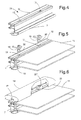
figure 1 represents the perspective view of the internal side of a door, window or shutter; -
figure 2 represents a rotated cross-section view of the detail A offigure 1 , as well as the cross-section of a composite section bar according to a first particular embodiment of the invention; -
Figure 3 shows an exploded perspective view of the composite section bar ofFigure 2 ; -
Figure 3A shows a perspective view of a coupling device of the composite section bar offigure 3 ; -
figures 4 - 5 - 6 each represent the partially exploded view of the sequences relative to the method and to the formation process of a composite section bar, which is wholly indicated withreference numeral 24 according to a preferred embodiment of the invention; -
figures 7 and8 show a first and a second side view of the composite section bar ofFigure 2 , according to the rotation axis of a coupling device-before the start and after the completion of the coupling rotation of the hooking device, respectively; -
Figure 9 shows an exploded perspective view of some components of a composite section bar according to one second particular embodiment of the invention; -
Figure 10 shows a partially broken perspective view of the composite section bar ofFigure 9 , after assembly; -
Figure 11 shows a perspective view of a coupling device of the composite section bar ofFigure 9 ; -
Figure 12 shows a view, according to an axial direction, of the coupling device offigure 11 , and of the relative tool. - With reference to
figures 1 , 2 and 3 it is observed that the invention concerns an assembly of section bars for doors, windows and shutters that is characterised in that it comprises: - a first metal section bar element (7), with the function of a strong and load-bearing structure, which is provided with a tube (8) and that is provided, on the face facing inwards, with an undercut seat (9), whereas on the face parallel, and opposite to it, it is provided with a wing (10) that is perpendicular to the tube with the function of resting and fixedly externally holding the sheet of glass (11);
- a second element, also a section bar, in synthetic material (12), i.e. in plastic material provided with through slots (13) in a position that is, for example, equidistant along its length, that is shaped so as to have longitudinal ribs (14) and grooves (14'), that are useful for keeping the dimensional stability and for creating air chambers for improving the acoustic and thermal performances, which are arranged so that in the slotted area (13) they can create a single undercut seat (15);
- a third shaped element made of wood (16) or in any case of another decorative material, to be coupled with the aforementioned elements, which is provided with an undercut groove (17) that is preferably dove-tail shaped;
- at least one device (18) that is formed by a central body or shank (19) that is substantially cylindrical equipped at the ends and in the middle with three eccentric shaped heads (20 , 20', 20") as well as with a further figure with a suitable thickness and the shape of a cam (21), with one side (22) that is longer than the other one (23) arranged in a position that is perpendicular with respect to the first one, and positioned between one of the end heads (20") and the head in the middle position (20'). The cam figures 21, 21' are also indicated, in the present description, as " driving
head other heads figures 3A ,11 , the cam figures 21, 21' can substantially form flanges or plates that project radially from the sides of the coupling device (18). The cam-shaped figure 21 preferably has the shape of a lever that, before the rotation that engages the first eccentric head (20) with the metal section bar (7), the second eccentric head (20') with the section bar made of synthetic material (12) and the third eccentric head (20") with the wooden section bar, projects outside from the wooden section bar and can be gripped by hand, or in any case actuated from outside of the wooden section bar itself. - The
section bar 12 can be made for example in polyvinyl chloride (PVC) or other material. - The coupling devices (18) can be made for example through injection moulding in a suitable plastic material.
- The structure of the
composite section bar 24, formed by the three different elements made of different material, with the device that allows it to be formed, can be understood more clearly with reference tofigures 2 and 3 . - The metal section bar (7) in the undercut seat oriented towards the interior (9) receives, resting adjacently against it, the element in synthetic material (12) provided with through slots (13) that are arranged for example at a constant pitch for its length. Such slots (13) in their formation and in their location make it possible to free the element (12) from the ribs and cavities (14 e 14') thus creating a single undercut seat (15). The synthetic section bar (12) can be fixed also only temporarily, by hooking with the metal one (7) with pressure wings or other mechanical joints.
- Once it has been inserted, the coupling device (18) passes through the
slots 13 until the eccentric head is positioned (20) in the undercut (9) of the metal section bar (7) and the middle eccentric (20') in the single undercut (15) of the synthetic section bar (12) created by the slot (13). The cam figure (21) acts, in addition to as a spacer for its thickness, also as an internal holding element for the sheet of glass (11) with its short side (23) pressing on the edge of such an element. The shaped wooden element (16) in its undercut seat (17) receives the other eccentric head (20") of the device (18). - The process for forming the section bar obtained by connecting the three elements made of different material, obtained by means of the device (18), occurs according to the following description with reference to
figures 4, 5 and 6 . - The synthetic section bar (12) already provided with through slots (13) carried out for example with a constant pitch for its entire length, is rested against the metal section bar (7).
- The sheet of glass (11) is positioned and rested on the suitable wing (10) of the metal section bar (7) and the connection devices (18) are positioned through the slots (13) until the undercut seat (9) is reached by the eccentric head (20) of the device itself; preferably the devices (18) are inserted in the slots (13) so that an end part of the cam figure (21) protrudes out from the edge of the metal section bar (7), and preferably also out from the edge of the wooden section bar (16).
- The shaped wooden element (16) is rested by using the dove-tail shaped (17) seat as a guide, the latter being engaged by the other eccentric head (20") of the device (18).
- Finally, by acting on the long side (22) or lever extension (22) of the cam figure (21) so as to exert a rotation for example of 90° along the longitudinal axis AL of the cylindrical body (19) of the device (18), the simultaneous fixed engagement will be obtained with one another and at the same time the positioning will be obtained of the short side (23) resting on the inner edge of the glass (11) keeping it in its seat. Indeed, following the 90° rotation, the
eccentric head 20 hooks inside an undercut of themetal section bar 7, the intermediate eccentric head 20' hooks a second undercut of thesynthetic section bar 12 and the thirdeccentric head 20" hooks thewooden section bar 16. In such a way the three section bars are axially locked on thecoupling devices 18 without being able to come off from them. Moreover, theeccentrics devices 18 themselves. For example, when the rotation is completed, thecoupling devices 18 prevent thesection bars Figure 2 , vertically. After the rotation of theeccentrics section bars - For such a purpose, when the first eccentric head (20) is inserted inside the metal section bar (7), the second eccentric head (20') is inserted inside the section bar made of synthetic material (12) and the third eccentric head (20") is inserted inside the wooden section bar (16), and before rotating the coupling device (18) around the longitudinal axis (AL) of its shank, the lever (19) advantageously protrudes out from the wooden section bar (16), so as to be able to be for example gripped or actuated with the fingers of a hand: this type of manual assembly of the coupling devices (18) has been found to be very valid, in some cases to an extent such as to make it possible to assemble doors, windows and shutters with production rates that are not slower than those obtained by actuating the
devices 18 with tools. -
Reference numerals Figure 2 respectively indicate two outer and inner gaskets with which the door, window or shutter is preferably provided. Differently from known doors, windows and shutters, theinner gasket 102 can exclusively have an aesthetic function, i.e. closing the gap between the glass and thewooden section bar 16 created by the interposition of the driving heads 21: indeed in known doors, windows and shutters theinner gasket 102 also has the structural function of transmitting the pressure, which the wind and other weather conditions apply from outside onto the glass sheet, to the wooden section bar; in a door, window or shutter according to the invention, on the other hand, the thrust of the external weather conditions can be exclusively discharged onto thecoupling devices 18 and from these onto themetal section bar 7. Therefore, the selection and the assembly of theinner gasket 102 are a lot less critical with respect to the state of the art. - Preferably, the eccentric heads 20, 20', 20" are each substantially parallelepiped-shaped with two corners that are diagonally opposite one another 200, 200A -with reference to the faces that are transversal with respect to the axes AL- more rounded with respect to the other two diagonally opposite
corners heads eccentric head mechanical abutments - As shown in
Figures 7 ,8 such a shape makes it possible to stop the rotation of thecoupling devices 18 again in the same angular position. In such an angular stopping position the clearances between the sides of theeccentrics insulated glazing 11, is completely supported by themetal section bar 7 and by thecoupling devices 18. - The possible dismounting of the composite section bar thus formed is obtained by following the method according to operations that are reverse with respect to those just described.
- From what has been previously described, it is clear how the finding achieves the proposed purposes.
- As can be easily understood, the method used by the device, characterised by having the three eccentric heads (20 , 20'
e 20") as well as the cam figure (21) as appendages of the cylindrical body (19) that form it, is that of engaging the different elements constituting the system including the glass, in an independent and aimed manner for each of them but with its single body which indeed has the origin of the coupling on the metal section bar (7) itself discharging and transmitting all the mechanical stresses, which can arise from the other connected elements, precisely to this. Thecomposite section bar 24 is very cost-effective and quick to assemble, since the operations of only inserting and rotating thecoupling devices 18 join together four elements; the three section bars, metal- 7, synthetic 12-and wooden-section bar 16, as well as the glass sheet orinsulated glazing 11. The assembly through thecoupling devices 18 makes it possible to assemble the threesection bars Figures 9-12 are relative to a second embodiment of a composite section bar according to the invention and wholly indicated with reference numeral 24'. In such an embodiment, each coupling device 18' is provided with an driving head 21' which is arranged for being engaged with atool 26 that makes it possible to rotate the head 21' itself so as to fix it to the section bars inmetal 7, inwood 16 and insynthetic material 12 and assemble the composite section bar 24'. Thetool 26 can be, for example, a special mechanical wrench like the one shown inFigure 12 , a hexagon wrench or other suitable standard wrench. Thetool 26 can be provided with afirst projection 260 that is arranged for being inserted in asuitable notch 210 that is formed in the driving head 21'. Thetool 26 can be provided with asecond projection 262 that is arranged suitable for being engaged with an external edge - for example rectilinear- of the driving head 21'. Thetool 26 or also other tools, make it possible to assemble a composite section bar 24' more easily and faster than with bare hands. Indeed in order to assemble the composite section bar 24' the section bars inmetal 7 and inplastic 12 are assembled; after which the various devices 18' are inserted in the slots 13 (Figure 9 ). When thewooden section bar 16 is arranged over thesynthetic section bar 12, a gap is temporarily formed between them. Thetools 26 can be introduced very easily in such a gap, and reach and rotate the driving heads 21' rather than rotating the heads 21' with bare hands. Thetools 26 furthermore make it possible to rotate the driving heads 21' more easily until they are completely hidden between the section bars 12 and 16, and are not visible from outside (Figure 10 ). Thetool 26 can be part of the kit with which the various components of the composite section bar 24' are provided. - The object of the invention as conceived and as previously described can undergo numerous modifications and variants and, as such, are all covered by the same inventive concept. For example, the substantially cylindrical central body (19) can be more generically replaced by a suitably shaped shank or pin. Moreover, all the details can be replaced by technically equivalent elements, and in practice the materials used, the alternative aesthetic shapes as well as the sizes can be any according to the requirements of the specific application. It should be understood that an expression of the type "A comprises B, C, D" or "A is formed by B, C, D" comprises and describes also the particular case in which "A is made up of B, C, D". The examples and lists of possible variants of the present application should be intended as non-exhaustive lists.
Claims (11)
- Composite section bar (24, 24') for example for closures such as doors or windows, comprising a metal section bar (7), a wooden section bar (16), a section bar made of synthetic material (12), at least one coupling device (18), and wherein:- the coupling device forms a shank (19) and at least a first (20), a second (20') and a third eccentric head (20") arranged in succession along the shank and projecting radially from it with respect to the longitudinal axis (AL) of the shank;- the coupling device is arranged for being inserted in at least one through opening formed in the section bar made of synthetic material (12) and, following a rotation by a predetermined amount around the longitudinal axis (AL) thereof, causes the following:- the first eccentric head (20) hooks to an undercut of the metal section bar (7);- the third eccentric head (20") hooks to an undercut of the wooden section bar (16);- the second eccentric head (20'), located in an intermediate position between the first and the third head, hooks to an undercut of the section bar made of synthetic material (12);wherein following the rotation by a predetermined amount, the first (20), the second (20') and the third eccentric head (20") prevent the section bars made of wood, synthetic material and metal from coming off from the coupling device in an axial direction, stopping or in any case reducing the mutual sliding clearances of the various section bars, in radial directions.
- Composite section bar (24, 24') according to claim 1, wherein the coupling device (18, 18') is provided with an driving head (21, 21') arranged between the second (20') and the third eccentric head (20") and arranged so as to be driven, by hand or by means of a suitable tool (26), so as to rotate the coupling device (18, 18') around the longitudinal axis (AL) and fixing it to one or more from the metal section bar (7), the section bar made of synthetic material (12) and the wooden section bar (16).
- Composite section bar (24, 24') according to claim 2, wherein at least part of the driving heads (21) form a lever (19) projecting radially from the shank of the same coupling device (18).
- Composite section bar (24, 24') according to claim 2 or 3, wherein when the first eccentric head (20) is inserted into the metal section bar (7), the second eccentric head (20') is inserted into the section bar made of synthetic material (12) and the third eccentric head (20") is inserted inside the wooden section bar (16), and before rotating the coupling device (18) around the longitudinal axis (AL) of its shank the lever (19) projects outwards from the wooden section bar (16), so as to be able to be for example gripped or driven with the fingers of a hand.
- Composite section bar (24, 24') according to claim 1, arranged in such a way that each coupling device (18), when rotating around the longitudinal axis (AL) of its shank (19), presses the metal section bar (7), the section bar made of synthetic material (12) and the wooden section bar (16), like in a pack.
- Section bar for doors, windows and shutters obtained by connecting three elements made of different material with a relative method and device for the formation thereof simultaneously holding the glass wherein the structure of the section bar formed by the three different elements made of different material, with the device allowing it to be formed, is characterised in that the metal section bar (7) in the possible inward facing undercut seat (9) receives, resting adjacently against it, the element in synthetic material (12) provided with through slots (13) possibly arranged at a constant pitch along its length, such slots (13), in their formation and in their location, release the element (12) from the ribs and cavities (14 e 14') thus creating a single undercut seat (15), the device (18) passes through the slots until the eccentric head (20) is positioned in the undercut (9) of the metal section bar (7) and the middle eccentric (20') in the single undercut (15) of the synthetic section bar (12) created by the slot (13), the cam figure (21) in addition to acting as a spacer element for its thickness, with its short side (23) acts as an inner holding element for the sheet of glass (11) pressing on the edge of such a body, the shaped wooden element (16) in its undercut seat(17) receives the other eccentric head (20") of the device (18), and said structure thus formed with the feature of engaging the different elements forming the system including the glass in an independent and targeted manner for each of them, with the single body of the device (18) indeed having the origin of its own coupling on the metal section bar discharging and transmitting all the mechanical stresses only to this.
- Section bar for closures such as doors, windows and shutters obtained by connecting three elements made of different material with a relative method and device for making it, simultaneously obtaining the holding of the glass, according to claim 1 or 6, characterised by comprising:- a first metal section bar element(7), with functions of a strong and load-bearing structure provided with a tube (8) and provided, on the face facing inwards, with an undercut seat (9), whereas on the face parallel, and opposite to it, is provided with a wing (10) perpendicular to the tubular structure with the function of supporting and externally fixedly holding the sheet of glass (11);- a second element, also of the section bar type, made of synthetic material (12), provided with through slots (13) arranged equidistantly along its length, shaped so as to have longitudinal ribs (14) and grooves (14'), useful for keeping the dimensional stability and for forming air chambers for improving the acoustic and thermal performances, arranged so as to form a single undercut seat (15) in the slotted area (13) ;- a third shaped element made of wood (16) or of any other decorative material, to be coupled with the aforementioned elements, provided with an undercut groove (17) preferably dove-tail shaped;- finally, a device (18) formed by a cylindrical central body (19) provided, at the ends and in the middle, with three eccentric shaped heads (20 , 20' , 20") as well as with a further figure having a suitable thickness and the shape of a cam (21), having one side (22) longer than the other (23) arranged perpendicularly to the first one and arranged between one of the end heads (20") and the head in the middle position (20').
- Section bar for closures such as doors, windows and shutters according to claims 6 and 7, wherein the coupling device (18) is provided with eccentric heads (20 , 20' and 20") shaped for the stable and fixed interference engagement with the undercut seats (9, 15 and 17) of the three elements (7, 12 and 16) during its locking at 90° through the action on the long side (22) of the cam figure (21), whereas the short side (23) thereof, simultaneously and for the same locking action, is positioned on the inner edge of the glass (11) keeping it in its seat.
- Closure for doors windows or shutters comprising a panel made of transparent glass or plastic material, and an outer frame surrounding the panel and in turn comprising one or more portions of composite section bars (24, 24') having the features according to claim 1, and the driving head (21, 21') presses against the panel at least in the direction longitudinal with respect to the shank (19).
- Supply Kit comprising a composite section bar (24, 24') having the features according to claim 1 or 6 and comprising the disassembled components for putting such a composite section bar together, and a tool (26) arranged for engaging with the driving head (21, 21') making it possible to rotate it and fix the at least one coupling device (18') to the metal section bar (7), to the wooden section bar (16) and to the section bar made of synthetic material (12).
- Process for reversibly assembling the section bar for closures such as doors, windows and shutters having the features according to claim 1 or 6 and obtained by connecting three elements (7, 12, 16) made of different material consisting of the following steps:- the synthetic section bar (12) already provided with through slots (13) formed at a constant pitch over the whole length thereof is rested against the metal section bar (7);- the sheet of glass (11) is rested and positioned on the suitable wing (10) of the metal section bar (7) and the connection devices (18) are positioned through the slots (13) until the undercut seat (9) is reached by the eccentric head (20) of the device itself;- the shaped wooden element (16) is rested by using the dove-tail shaped seat (17) as a guide since this is engaged by the other eccentric head (20") of the device (18);- finally, acting on the long side (22) of the cam figure (21) so as to carry out a rotation of 90° along the axis of the cylindrical body (19) of the device (18), the simultaneous fixed engagement with one another is obtained and at the same time the short side (23) is rested on the inner edge of the glass (11), keeping it in its seat.
Applications Claiming Priority (2)
| Application Number | Priority Date | Filing Date | Title |
|---|---|---|---|
| IT000002A ITRG20130002A1 (en) | 2013-06-27 | 2013-06-27 | PROFILE FOR WINDOW FRAMES OBTAINED BY CONNECTING THREE ELEMENTS OF DIFFERENT MATERIALS WITH ITS METHOD AND DEVICE FOR HIS TRAINING REALIZING THE CONTEMPORARY GLASS RETAINING |
| ITMI20131932 ITMI20131932A1 (en) | 2013-06-27 | 2013-11-20 | COMPOSITE PROFILE FOR WINDOWS, AND PROCEDURE FOR REALIZING IT |
Publications (2)
| Publication Number | Publication Date |
|---|---|
| EP2818621A1 true EP2818621A1 (en) | 2014-12-31 |
| EP2818621B1 EP2818621B1 (en) | 2017-01-11 |
Family
ID=49263349
Family Applications (1)
| Application Number | Title | Priority Date | Filing Date |
|---|---|---|---|
| EP14173738.7A Active EP2818621B1 (en) | 2013-06-27 | 2014-06-24 | Composite section bar for doors, windows and shutters, and process for manufacture it |
Country Status (2)
| Country | Link |
|---|---|
| EP (1) | EP2818621B1 (en) |
| IT (2) | ITRG20130002A1 (en) |
Cited By (1)
| Publication number | Priority date | Publication date | Assignee | Title |
|---|---|---|---|---|
| IT202000017842A1 (en) * | 2020-07-23 | 2022-01-23 | Europrofili Group S P A | CLOSING SYSTEM WITH FIXING DEVICE |
Citations (5)
| Publication number | Priority date | Publication date | Assignee | Title |
|---|---|---|---|---|
| ITRG950001A1 (en) * | 1995-01-02 | 1996-07-02 | Giuseppe Bracchitta | COMPLEX OF PROFILES FOR FRAMES OBTAINED BY CONNECTING TWO ELEMENTS OF DIFFERENT MATERIALS WITH THE RELEVANT METHOD AND DEVICE FOR THEIR |
| WO2000050722A1 (en) * | 1999-02-25 | 2000-08-31 | Osmet S.P.A. | Composite section for door or window frames |
| EP1338746A2 (en) * | 2002-02-22 | 2003-08-27 | Indinvest S.p.A. | Frame for doors or windows of the type with metal profiles on the outer side and with wood cladding on the inner side |
| EP2085557A2 (en) * | 2008-02-04 | 2009-08-05 | Ferro Group International S.r.l. | Multi-layered profile for frames for doors, windows and suchlike |
| EP2385207A2 (en) * | 2010-02-16 | 2011-11-09 | Dfv S.R.L. | System for producing high insulating aluminium-wood mixed window and door frames |
-
2013
- 2013-06-27 IT IT000002A patent/ITRG20130002A1/en unknown
- 2013-11-20 IT ITMI20131932 patent/ITMI20131932A1/en unknown
-
2014
- 2014-06-24 EP EP14173738.7A patent/EP2818621B1/en active Active
Patent Citations (5)
| Publication number | Priority date | Publication date | Assignee | Title |
|---|---|---|---|---|
| ITRG950001A1 (en) * | 1995-01-02 | 1996-07-02 | Giuseppe Bracchitta | COMPLEX OF PROFILES FOR FRAMES OBTAINED BY CONNECTING TWO ELEMENTS OF DIFFERENT MATERIALS WITH THE RELEVANT METHOD AND DEVICE FOR THEIR |
| WO2000050722A1 (en) * | 1999-02-25 | 2000-08-31 | Osmet S.P.A. | Composite section for door or window frames |
| EP1338746A2 (en) * | 2002-02-22 | 2003-08-27 | Indinvest S.p.A. | Frame for doors or windows of the type with metal profiles on the outer side and with wood cladding on the inner side |
| EP2085557A2 (en) * | 2008-02-04 | 2009-08-05 | Ferro Group International S.r.l. | Multi-layered profile for frames for doors, windows and suchlike |
| EP2385207A2 (en) * | 2010-02-16 | 2011-11-09 | Dfv S.R.L. | System for producing high insulating aluminium-wood mixed window and door frames |
Cited By (1)
| Publication number | Priority date | Publication date | Assignee | Title |
|---|---|---|---|---|
| IT202000017842A1 (en) * | 2020-07-23 | 2022-01-23 | Europrofili Group S P A | CLOSING SYSTEM WITH FIXING DEVICE |
Also Published As
| Publication number | Publication date |
|---|---|
| ITRG20130002A1 (en) | 2014-12-28 |
| EP2818621B1 (en) | 2017-01-11 |
| ITMI20131932A1 (en) | 2014-12-28 |
Similar Documents
| Publication | Publication Date | Title |
|---|---|---|
| US4098555A (en) | Device for joining two structural parts | |
| US8596017B2 (en) | Frame members, corner key and assembly method | |
| KR101750037B1 (en) | Curtain wall closing the cover of the quick-detachable manner | |
| KR101166100B1 (en) | Device for assembling laminated glass panes | |
| EP2456933A1 (en) | Method for producing a building having a prefabricated wood framework, and resulting building | |
| WO2017201589A4 (en) | Curtain wall and set and construction method for such a curtain wall | |
| MXPA06014439A (en) | Hinge attachment system and method. | |
| EP2818621B1 (en) | Composite section bar for doors, windows and shutters, and process for manufacture it | |
| DE202011101654U1 (en) | Thermally separated profile | |
| EP2769105B1 (en) | Device for fixing insulating layers and insulation assembly system | |
| US10648226B2 (en) | Main-frame bar and/or wing-frame bar, and door, window, or façade element | |
| ITTO20110354A1 (en) | QUICK FIXING SYSTEM, IN PARTICULAR FOR FASTENING PHOTOVOLTAIC SOLAR PANELS | |
| KR101896749B1 (en) | manufacturing method of composite materials window | |
| HRP970557A2 (en) | Heat-insulated composite profiled section, particularly for the frames of doors, windows, facade elements and the like | |
| EP3844363B1 (en) | Frame connector | |
| WO1997025537A1 (en) | Method of assembling frames and/or pieces of furniture by mechanical means without using any adhesive | |
| WO2013105121A1 (en) | Method for joining and coupling a couple of profiles of different materials, constituting the leaf and the frame of an external fixture | |
| EP3423659B1 (en) | Composite profiled element for a door, a window, or a façade element, and method for producing the composite profiled element | |
| EP1496188A2 (en) | Composite frame for doors and windows | |
| GB2536661A (en) | Weldable elements, joints and associated methods | |
| KR101864615B1 (en) | Construct ability improved windows and doors frame | |
| ITRG950001A1 (en) | COMPLEX OF PROFILES FOR FRAMES OBTAINED BY CONNECTING TWO ELEMENTS OF DIFFERENT MATERIALS WITH THE RELEVANT METHOD AND DEVICE FOR THEIR | |
| WO2018202960A1 (en) | System for adding a trim to the edge of an opening in a partition | |
| NL1002780C1 (en) | Renovation of rotten wooden frames | |
| US3994112A (en) | Framing member and joints |
Legal Events
| Date | Code | Title | Description |
|---|---|---|---|
| PUAI | Public reference made under article 153(3) epc to a published international application that has entered the european phase |
Free format text: ORIGINAL CODE: 0009012 |
|
| 17P | Request for examination filed |
Effective date: 20140624 |
|
| AK | Designated contracting states |
Kind code of ref document: A1 Designated state(s): AL AT BE BG CH CY CZ DE DK EE ES FI FR GB GR HR HU IE IS IT LI LT LU LV MC MK MT NL NO PL PT RO RS SE SI SK SM TR |
|
| AX | Request for extension of the european patent |
Extension state: BA ME |
|
| R17P | Request for examination filed (corrected) |
Effective date: 20150629 |
|
| RBV | Designated contracting states (corrected) |
Designated state(s): AL AT BE BG CH CY CZ DE DK EE ES FI FR GB GR HR HU IE IS IT LI LT LU LV MC MK MT NL NO PL PT RO RS SE SI SK SM TR |
|
| GRAP | Despatch of communication of intention to grant a patent |
Free format text: ORIGINAL CODE: EPIDOSNIGR1 |
|
| RIC1 | Information provided on ipc code assigned before grant |
Ipc: E06B 3/58 20060101ALN20160722BHEP Ipc: E06B 3/263 20060101ALI20160722BHEP Ipc: E06B 3/30 20060101AFI20160722BHEP Ipc: E06B 3/54 20060101ALN20160722BHEP |
|
| INTG | Intention to grant announced |
Effective date: 20160811 |
|
| RIC1 | Information provided on ipc code assigned before grant |
Ipc: E06B 3/263 20060101ALI20160801BHEP Ipc: E06B 3/58 20060101ALN20160801BHEP Ipc: E06B 3/30 20060101AFI20160801BHEP Ipc: E06B 3/54 20060101ALN20160801BHEP |
|
| GRAS | Grant fee paid |
Free format text: ORIGINAL CODE: EPIDOSNIGR3 |
|
| GRAA | (expected) grant |
Free format text: ORIGINAL CODE: 0009210 |
|
| AK | Designated contracting states |
Kind code of ref document: B1 Designated state(s): AL AT BE BG CH CY CZ DE DK EE ES FI FR GB GR HR HU IE IS IT LI LT LU LV MC MK MT NL NO PL PT RO RS SE SI SK SM TR |
|
| REG | Reference to a national code |
Ref country code: GB Ref legal event code: FG4D |
|
| REG | Reference to a national code |
Ref country code: CH Ref legal event code: EP |
|
| REG | Reference to a national code |
Ref country code: AT Ref legal event code: REF Ref document number: 861469 Country of ref document: AT Kind code of ref document: T Effective date: 20170115 |
|
| REG | Reference to a national code |
Ref country code: IE Ref legal event code: FG4D |
|
| REG | Reference to a national code |
Ref country code: DE Ref legal event code: R096 Ref document number: 602014006141 Country of ref document: DE |
|
| REG | Reference to a national code |
Ref country code: LT Ref legal event code: MG4D |
|
| REG | Reference to a national code |
Ref country code: NL Ref legal event code: MP Effective date: 20170111 |
|
| REG | Reference to a national code |
Ref country code: AT Ref legal event code: MK05 Ref document number: 861469 Country of ref document: AT Kind code of ref document: T Effective date: 20170111 |
|
| PG25 | Lapsed in a contracting state [announced via postgrant information from national office to epo] |
Ref country code: NL Free format text: LAPSE BECAUSE OF FAILURE TO SUBMIT A TRANSLATION OF THE DESCRIPTION OR TO PAY THE FEE WITHIN THE PRESCRIBED TIME-LIMIT Effective date: 20170111 |
|
| PG25 | Lapsed in a contracting state [announced via postgrant information from national office to epo] |
Ref country code: FI Free format text: LAPSE BECAUSE OF FAILURE TO SUBMIT A TRANSLATION OF THE DESCRIPTION OR TO PAY THE FEE WITHIN THE PRESCRIBED TIME-LIMIT Effective date: 20170111 Ref country code: IS Free format text: LAPSE BECAUSE OF FAILURE TO SUBMIT A TRANSLATION OF THE DESCRIPTION OR TO PAY THE FEE WITHIN THE PRESCRIBED TIME-LIMIT Effective date: 20170511 Ref country code: HR Free format text: LAPSE BECAUSE OF FAILURE TO SUBMIT A TRANSLATION OF THE DESCRIPTION OR TO PAY THE FEE WITHIN THE PRESCRIBED TIME-LIMIT Effective date: 20170111 Ref country code: GR Free format text: LAPSE BECAUSE OF FAILURE TO SUBMIT A TRANSLATION OF THE DESCRIPTION OR TO PAY THE FEE WITHIN THE PRESCRIBED TIME-LIMIT Effective date: 20170412 Ref country code: LT Free format text: LAPSE BECAUSE OF FAILURE TO SUBMIT A TRANSLATION OF THE DESCRIPTION OR TO PAY THE FEE WITHIN THE PRESCRIBED TIME-LIMIT Effective date: 20170111 Ref country code: NO Free format text: LAPSE BECAUSE OF FAILURE TO SUBMIT A TRANSLATION OF THE DESCRIPTION OR TO PAY THE FEE WITHIN THE PRESCRIBED TIME-LIMIT Effective date: 20170411 |
|
| PG25 | Lapsed in a contracting state [announced via postgrant information from national office to epo] |
Ref country code: PL Free format text: LAPSE BECAUSE OF FAILURE TO SUBMIT A TRANSLATION OF THE DESCRIPTION OR TO PAY THE FEE WITHIN THE PRESCRIBED TIME-LIMIT Effective date: 20170111 Ref country code: SE Free format text: LAPSE BECAUSE OF FAILURE TO SUBMIT A TRANSLATION OF THE DESCRIPTION OR TO PAY THE FEE WITHIN THE PRESCRIBED TIME-LIMIT Effective date: 20170111 Ref country code: ES Free format text: LAPSE BECAUSE OF FAILURE TO SUBMIT A TRANSLATION OF THE DESCRIPTION OR TO PAY THE FEE WITHIN THE PRESCRIBED TIME-LIMIT Effective date: 20170111 Ref country code: RS Free format text: LAPSE BECAUSE OF FAILURE TO SUBMIT A TRANSLATION OF THE DESCRIPTION OR TO PAY THE FEE WITHIN THE PRESCRIBED TIME-LIMIT Effective date: 20170111 Ref country code: AT Free format text: LAPSE BECAUSE OF FAILURE TO SUBMIT A TRANSLATION OF THE DESCRIPTION OR TO PAY THE FEE WITHIN THE PRESCRIBED TIME-LIMIT Effective date: 20170111 Ref country code: PT Free format text: LAPSE BECAUSE OF FAILURE TO SUBMIT A TRANSLATION OF THE DESCRIPTION OR TO PAY THE FEE WITHIN THE PRESCRIBED TIME-LIMIT Effective date: 20170511 Ref country code: LV Free format text: LAPSE BECAUSE OF FAILURE TO SUBMIT A TRANSLATION OF THE DESCRIPTION OR TO PAY THE FEE WITHIN THE PRESCRIBED TIME-LIMIT Effective date: 20170111 Ref country code: BG Free format text: LAPSE BECAUSE OF FAILURE TO SUBMIT A TRANSLATION OF THE DESCRIPTION OR TO PAY THE FEE WITHIN THE PRESCRIBED TIME-LIMIT Effective date: 20170411 |
|
| REG | Reference to a national code |
Ref country code: DE Ref legal event code: R097 Ref document number: 602014006141 Country of ref document: DE |
|
| PG25 | Lapsed in a contracting state [announced via postgrant information from national office to epo] |
Ref country code: RO Free format text: LAPSE BECAUSE OF FAILURE TO SUBMIT A TRANSLATION OF THE DESCRIPTION OR TO PAY THE FEE WITHIN THE PRESCRIBED TIME-LIMIT Effective date: 20170111 Ref country code: SK Free format text: LAPSE BECAUSE OF FAILURE TO SUBMIT A TRANSLATION OF THE DESCRIPTION OR TO PAY THE FEE WITHIN THE PRESCRIBED TIME-LIMIT Effective date: 20170111 Ref country code: CZ Free format text: LAPSE BECAUSE OF FAILURE TO SUBMIT A TRANSLATION OF THE DESCRIPTION OR TO PAY THE FEE WITHIN THE PRESCRIBED TIME-LIMIT Effective date: 20170111 Ref country code: EE Free format text: LAPSE BECAUSE OF FAILURE TO SUBMIT A TRANSLATION OF THE DESCRIPTION OR TO PAY THE FEE WITHIN THE PRESCRIBED TIME-LIMIT Effective date: 20170111 |
|
| PLBE | No opposition filed within time limit |
Free format text: ORIGINAL CODE: 0009261 |
|
| STAA | Information on the status of an ep patent application or granted ep patent |
Free format text: STATUS: NO OPPOSITION FILED WITHIN TIME LIMIT |
|
| PG25 | Lapsed in a contracting state [announced via postgrant information from national office to epo] |
Ref country code: DK Free format text: LAPSE BECAUSE OF FAILURE TO SUBMIT A TRANSLATION OF THE DESCRIPTION OR TO PAY THE FEE WITHIN THE PRESCRIBED TIME-LIMIT Effective date: 20170111 Ref country code: SM Free format text: LAPSE BECAUSE OF FAILURE TO SUBMIT A TRANSLATION OF THE DESCRIPTION OR TO PAY THE FEE WITHIN THE PRESCRIBED TIME-LIMIT Effective date: 20170111 |
|
| 26N | No opposition filed |
Effective date: 20171012 |
|
| REG | Reference to a national code |
Ref country code: DE Ref legal event code: R119 Ref document number: 602014006141 Country of ref document: DE |
|
| PG25 | Lapsed in a contracting state [announced via postgrant information from national office to epo] |
Ref country code: MC Free format text: LAPSE BECAUSE OF FAILURE TO SUBMIT A TRANSLATION OF THE DESCRIPTION OR TO PAY THE FEE WITHIN THE PRESCRIBED TIME-LIMIT Effective date: 20170111 |
|
| REG | Reference to a national code |
Ref country code: CH Ref legal event code: PL |
|
| PG25 | Lapsed in a contracting state [announced via postgrant information from national office to epo] |
Ref country code: SI Free format text: LAPSE BECAUSE OF FAILURE TO SUBMIT A TRANSLATION OF THE DESCRIPTION OR TO PAY THE FEE WITHIN THE PRESCRIBED TIME-LIMIT Effective date: 20170111 |
|
| REG | Reference to a national code |
Ref country code: IE Ref legal event code: MM4A |
|
| REG | Reference to a national code |
Ref country code: FR Ref legal event code: ST Effective date: 20180228 |
|
| PG25 | Lapsed in a contracting state [announced via postgrant information from national office to epo] |
Ref country code: LU Free format text: LAPSE BECAUSE OF NON-PAYMENT OF DUE FEES Effective date: 20170624 Ref country code: LI Free format text: LAPSE BECAUSE OF NON-PAYMENT OF DUE FEES Effective date: 20170630 Ref country code: IE Free format text: LAPSE BECAUSE OF NON-PAYMENT OF DUE FEES Effective date: 20170624 Ref country code: DE Free format text: LAPSE BECAUSE OF NON-PAYMENT OF DUE FEES Effective date: 20180103 Ref country code: CH Free format text: LAPSE BECAUSE OF NON-PAYMENT OF DUE FEES Effective date: 20170630 |
|
| PG25 | Lapsed in a contracting state [announced via postgrant information from national office to epo] |
Ref country code: FR Free format text: LAPSE BECAUSE OF NON-PAYMENT OF DUE FEES Effective date: 20170630 |
|
| REG | Reference to a national code |
Ref country code: BE Ref legal event code: MM Effective date: 20170630 |
|
| PG25 | Lapsed in a contracting state [announced via postgrant information from national office to epo] |
Ref country code: BE Free format text: LAPSE BECAUSE OF NON-PAYMENT OF DUE FEES Effective date: 20170630 |
|
| PG25 | Lapsed in a contracting state [announced via postgrant information from national office to epo] |
Ref country code: MT Free format text: LAPSE BECAUSE OF NON-PAYMENT OF DUE FEES Effective date: 20170624 |
|
| GBPC | Gb: european patent ceased through non-payment of renewal fee |
Effective date: 20180624 |
|
| PG25 | Lapsed in a contracting state [announced via postgrant information from national office to epo] |
Ref country code: GB Free format text: LAPSE BECAUSE OF NON-PAYMENT OF DUE FEES Effective date: 20180624 |
|
| PG25 | Lapsed in a contracting state [announced via postgrant information from national office to epo] |
Ref country code: HU Free format text: LAPSE BECAUSE OF FAILURE TO SUBMIT A TRANSLATION OF THE DESCRIPTION OR TO PAY THE FEE WITHIN THE PRESCRIBED TIME-LIMIT; INVALID AB INITIO Effective date: 20140624 |
|
| PG25 | Lapsed in a contracting state [announced via postgrant information from national office to epo] |
Ref country code: CY Free format text: LAPSE BECAUSE OF FAILURE TO SUBMIT A TRANSLATION OF THE DESCRIPTION OR TO PAY THE FEE WITHIN THE PRESCRIBED TIME-LIMIT Effective date: 20170111 |
|
| PG25 | Lapsed in a contracting state [announced via postgrant information from national office to epo] |
Ref country code: MK Free format text: LAPSE BECAUSE OF FAILURE TO SUBMIT A TRANSLATION OF THE DESCRIPTION OR TO PAY THE FEE WITHIN THE PRESCRIBED TIME-LIMIT Effective date: 20170111 |
|
| PG25 | Lapsed in a contracting state [announced via postgrant information from national office to epo] |
Ref country code: TR Free format text: LAPSE BECAUSE OF FAILURE TO SUBMIT A TRANSLATION OF THE DESCRIPTION OR TO PAY THE FEE WITHIN THE PRESCRIBED TIME-LIMIT Effective date: 20170111 |
|
| PG25 | Lapsed in a contracting state [announced via postgrant information from national office to epo] |
Ref country code: AL Free format text: LAPSE BECAUSE OF FAILURE TO SUBMIT A TRANSLATION OF THE DESCRIPTION OR TO PAY THE FEE WITHIN THE PRESCRIBED TIME-LIMIT Effective date: 20170111 |
|
| PGFP | Annual fee paid to national office [announced via postgrant information from national office to epo] |
Ref country code: IT Payment date: 20230530 Year of fee payment: 10 |