EP2818615B1 - Door handle assembly for a motor vehicle - Google Patents
Door handle assembly for a motor vehicle Download PDFInfo
- Publication number
- EP2818615B1 EP2818615B1 EP14170327.2A EP14170327A EP2818615B1 EP 2818615 B1 EP2818615 B1 EP 2818615B1 EP 14170327 A EP14170327 A EP 14170327A EP 2818615 B1 EP2818615 B1 EP 2818615B1
- Authority
- EP
- European Patent Office
- Prior art keywords
- locking device
- coupling device
- handle
- blocking
- door handle
- Prior art date
- Legal status (The legal status is an assumption and is not a legal conclusion. Google has not performed a legal analysis and makes no representation as to the accuracy of the status listed.)
- Active
Links
Images

Classifications
-
- E—FIXED CONSTRUCTIONS
- E05—LOCKS; KEYS; WINDOW OR DOOR FITTINGS; SAFES
- E05B—LOCKS; ACCESSORIES THEREFOR; HANDCUFFS
- E05B85/00—Details of vehicle locks not provided for in groups E05B77/00 - E05B83/00
- E05B85/10—Handles
- E05B85/14—Handles pivoted about an axis parallel to the wing
- E05B85/16—Handles pivoted about an axis parallel to the wing a longitudinal grip part being pivoted at one end about an axis perpendicular to the longitudinal axis of the grip part
-
- E—FIXED CONSTRUCTIONS
- E05—LOCKS; KEYS; WINDOW OR DOOR FITTINGS; SAFES
- E05B—LOCKS; ACCESSORIES THEREFOR; HANDCUFFS
- E05B77/00—Vehicle locks characterised by special functions or purposes
- E05B77/02—Vehicle locks characterised by special functions or purposes for accident situations
- E05B77/04—Preventing unwanted lock actuation, e.g. unlatching, at the moment of collision
- E05B77/06—Preventing unwanted lock actuation, e.g. unlatching, at the moment of collision by means of inertial forces
-
- E—FIXED CONSTRUCTIONS
- E05—LOCKS; KEYS; WINDOW OR DOOR FITTINGS; SAFES
- E05B—LOCKS; ACCESSORIES THEREFOR; HANDCUFFS
- E05B85/00—Details of vehicle locks not provided for in groups E05B77/00 - E05B83/00
- E05B85/10—Handles
-
- E—FIXED CONSTRUCTIONS
- E05—LOCKS; KEYS; WINDOW OR DOOR FITTINGS; SAFES
- E05B—LOCKS; ACCESSORIES THEREFOR; HANDCUFFS
- E05B77/00—Vehicle locks characterised by special functions or purposes
- E05B77/02—Vehicle locks characterised by special functions or purposes for accident situations
-
- Y—GENERAL TAGGING OF NEW TECHNOLOGICAL DEVELOPMENTS; GENERAL TAGGING OF CROSS-SECTIONAL TECHNOLOGIES SPANNING OVER SEVERAL SECTIONS OF THE IPC; TECHNICAL SUBJECTS COVERED BY FORMER USPC CROSS-REFERENCE ART COLLECTIONS [XRACs] AND DIGESTS
- Y10—TECHNICAL SUBJECTS COVERED BY FORMER USPC
- Y10S—TECHNICAL SUBJECTS COVERED BY FORMER USPC CROSS-REFERENCE ART COLLECTIONS [XRACs] AND DIGESTS
- Y10S292/00—Closure fasteners
- Y10S292/22—Inertia operated
-
- Y—GENERAL TAGGING OF NEW TECHNOLOGICAL DEVELOPMENTS; GENERAL TAGGING OF CROSS-SECTIONAL TECHNOLOGIES SPANNING OVER SEVERAL SECTIONS OF THE IPC; TECHNICAL SUBJECTS COVERED BY FORMER USPC CROSS-REFERENCE ART COLLECTIONS [XRACs] AND DIGESTS
- Y10—TECHNICAL SUBJECTS COVERED BY FORMER USPC
- Y10T—TECHNICAL SUBJECTS COVERED BY FORMER US CLASSIFICATION
- Y10T292/00—Closure fasteners
- Y10T292/57—Operators with knobs or handles
Definitions
- the invention is directed to a door handle assembly for a motor vehicle with a frame-like handle support, a manually operable handle, which is movably mounted on the handle support for opening a door or flap of the motor vehicle by a user, a pivotally mounted on the handle support coupling device by the movement the handle is transferable to a vehicle-side locking arrangement, and a locking device serving as a mass barrier, which is movably held on the handle carrier and is designed such that it is possible under the action of an accelerating force due to the inertia of their mass from a rest position in which actuation of the handle is, in a first blocking direction, in which an actuation of the closing arrangement is blocked by the handle and / or the coupling device is movable.
- Such door handle arrangements with a locking device serving as a mass barrier are intended to prevent the acceleration forces occurring in the event of an accident from leading to actuation of the handle or door handle and unintentional opening of the door of the motor vehicle, which entails considerable risks for an occupant of the vehicle.
- the user-operable gripping members are mechanically coupled to a vehicle-side locking assembly (the actual door lock).
- the movement of the door handle or the handle is transmitted by the coupling device to the closing arrangement and released the door to the opening.
- the acceleration forces under adverse conditions such as operation of the handle member by a user, since the handle can be accelerated due to the inertia in the opening direction.
- this describes DE 199 29 022 C2 a corresponding mass barrier in the form of a pivotable locking member which is to exclude a handle operation in the event of a crash.
- a door handle assembly is further, for example, from DE 10 2009 053 553 A1 known. In this door handle assembly acts by a crash barrier an additional force on the handle or the door handle, which should be reliably avoided that it comes to an unwanted movement of the handle.
- a door handle assembly of the type designated input with a designed in the form of a crash barrier device is for example from DE 10 2008 000 098 A1 known.
- crash barriers can be designed as a pendulum mass, so that displaced as a result of the applied force, the crash barrier, for example, in the path of movement of the handle and thereby blocks the handle.
- crash spears are known, which engage in a blocking position and can be deactivated again after their activation and latching only by a targeted intervention in the door handle unit, so that the door handle can be used again in normal operation.
- the known locking devices are active only in a relatively small Sperrweg- or Stellweg Scheme, which blocks an actuation of the coupling lever designed as a lever or the handle, so that either strong and pronounced vibrations or long-lasting vibrations due to The effect of acceleration forces there is a risk that, in the case of a reciprocating or oscillating locking device, the travel range is not designed to be sufficiently long in order to reliably prevent blocking of the handle or of the reversing lever. Therefore, in the event of a crash during the oscillation process, the locking device, despite its activation, can assume a position in which it does not block the handle or the lever.
- a further disadvantage is that the known door handle assemblies are designed with crash barrier only for a directed into the vehicle acceleration force. An acceleration force directed in the opposite direction is not taken into account but may also influence an undesired operation of the handle.
- the invention is therefore an object of the invention to provide a solution that provides a door handle assembly in a structurally simple manner and cost, in which the locking device reliably and safely blocks the handle or the coupling device even with alternating acceleration forces due to a crash.
- the object is achieved in that the locking device under the action of an acceleration force due to the inertia of their mass from the rest position in a second blocking direction, in which an actuation of the closure assembly is blocked by the handle and / or the coupling device, is designed to be movable, wherein the second blocking direction of the first blocking direction is opposite.
- the invention provides a door handle assembly of a motor vehicle is available, which is characterized by a functional design and has a simple and inexpensive construction. Characterized in that the locking device is formed movable under the action of an acceleration force from the rest position not only in a first blocking direction, but also in a second blocking direction, the range of application of the locking device, because this is no longer only in a single, predetermined Direction acting acceleration force activated, but also when an accelerating force in a second direction.
- This property of the locking device according to the invention is for example in a vehicle accident or crash case of advantage in which prevail due to the applied acceleration forces pronounced vibration processes, resulting in a swinging back and forth or oscillation or fluttering of the locking device between the rest position and a blocking position.
- the locking device can move in a second blocking direction in the event of a crash, the handle and / or the coupling device are effectively blocked even in the case of swinging back or oscillation of the locking device during a crash, because the locking device moves out when swinging back a first blocking position beyond the rest position in a second blocking direction, whereby the locking device at no time dwells in the rest position, but is passed through the rest position only for a minimum period of time.
- the blocking device is rotatably mounted on the handle carrier by means of a rotation axis and if the movement of the blocking device in the first and second blocking direction is a rotary movement of the blocking device.
- the axis of rotation to store the locking device rotatably in its center which also has a favorable effect on the installation space to be provided.
- the invention provides in a further embodiment that the locking device upon application of an acceleration force from the rest position to a maximum possible rotation angle to the Rotation axis is rotatable, wherein the rotation angle can be, for example, +/- 90 °, preferably +/- 270 °.
- This movement path of the locking device in its activation is sufficiently long, so that the crash state, which is characterized by the action of alternating acceleration forces and the associated oscillations or flutter movements of the vehicle structure, is completed even before the locking device moves back into its rest position due to their spring bias becomes.
- the locking device is part of a door handle assembly and can be provided for example in an exterior door handle, the weather and corrosion is exposed.
- the locking device is part of a door handle assembly and can be provided for example in an exterior door handle, the weather and corrosion is exposed.
- the desired and proper functionality of the (previously unactuated) locking device is present and enjoy the vehicle occupant optimal protection in a vehicle accident. It is therefore another task of the present invention, the operability of the door handle assembly and in particular the locking device, which is almost not operated for long periods to ensure.
- a pivoting movement of the coupling device as a result of a manual actuation of the handle causes a movement of the locking device in one of the two blocking directions without blocking the handle and / or the coupling device.
- a normal and thus manual operation of the handle and the action of an acceleration force lead to a rotational movement of the locking device.
- the handle is first manually operated by a user, with manual operation of the handle causing the locking device to rotate.
- the locking device is moved, which ensures that the rotatably mounted locking device is not clamped over time due to weather or even festkorroded.
- the constant movement of the locking device ensures that the locking device maintains its function even with a long service life.
- a rotational movement of the locking device takes place as a result of an acceleration force acting on the locking device. Due to different masses, the locking device is first moved under the action of an acceleration force, before the acceleration force then causes a deflection of the handle or the coupling device. However, since the locking device is already moving in a blocking direction, it will block the deflection of the coupling device and the handle.
- a structurally particularly favorable possibility of realizing a locking device, which undergoes a movement upon manual actuation of the handle and blocks a deflection of the handle upon exposure to an acceleration force as a result of a vehicle accident is given in an embodiment of the invention in that the coupling device is a pivotable together with her lever element having an angled approach, the pivoting of the Coupling device as a result of manual actuation of the handle in a - for example slot-shaped - recess of the locking device is immersed, wherein the angled approach presses in further, deflecting operation of the handle against the wall of the slot-shaped recess and thereby urges the locking device in one of the two blocking directions.
- the movement kinematics of the movement-coupled with the handle coupling device is used to directly attack the locking device and to move them from the rest position in the direction of one of the two blocking directions. In normal operation of the handle so the locking device is moved, which may be the case, for example, to a small extent.
- the locking device has a disk-shaped blocking body, in which the slot-shaped recess as a radially extending recess, in which the angled approach of the coupling device can pivot, is formed.
- the space to be provided for the locking device can be kept low in particular when the coupling device is mounted pivotably about a pivot axis on the handle carrier, wherein the axis of rotation of the locking device can be aligned substantially parallel to the pivot axis of the coupling device.
- the axis of rotation of the locking device is aligned at an angle to the axis of rotation of the locking device.
- a mechanical restoring element which applies a locking device urging the rest position force.
- the handle of the door handle assembly according to the invention thus after the action of acceleration forces is reusable and actuated, since the locking device is in the rest position again.
- the mechanical restoring element comprises an elastic spring element which is supported both on a stationary approach of the handle support and on a mitbedorfden with the locking element contact element, wherein upon movement of the locking device in the first or second blocking direction moves the abutment member relative to the approach against the force of the elastic spring element.
- FIG. 1 is a vehicle or motor vehicle 1 in the form of a car exemplified, which in the example has four doors 2, which can be opened via a door handle assembly 3 and in particular by means of a door handle or a handle 4.
- the doors 2 are tightly closed via respective closing arrangements 5 and can be opened from the outside only via a respective movement of the handle 4.
- This movement on the handle 4 may consist of a pulling and / or folding movement, wherein the corresponding movement of the handle 4 is mechanically transmitted at least via a coupling device to the corresponding closing arrangement 5.
- the corresponding locking assembly 5 and thus the associated door 2 can then open.
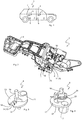
- FIG. 2 is a perspective view of the door handle assembly 3 shown in more detail.
- the door handle assembly 3 has a frame-like handle support 6, wherein for reasons of clarity in the FIGS. 2 to 10 on a representation of the handle 4 is omitted.
- the grip carrier 6 is known to be used for attaching the handle 4 and is fastened by means not shown screw on the inside of the door panel, wherein the handle 4 is arranged on the outside of the door.
- the grip carrier 6 for reasons of material saving is formed predominantly of a frame structure which has various receiving and storage spaces, in addition to the handle 4, which is movable on the handle support 6 for opening a corresponding door 2 of the motor vehicle 1 by a user and / / or is pivotally mounted on the handle support 6, also a to receive mechanical coupling device 7 and a locking device 8.
- the locking device 8 serving as a mass lock can change its position from a rest position into a blocking position when an acceleration force is applied, wherein in the rest position an actuation of the handle 4 is possible, whereas in the blocking position the locking device 8 movably held on the handle support 6 actuates the locking arrangement 5 is blocked by the handle 4 and / or a movement of the coupling device 7 by an actuation of the handle 4.
- the locking device 8 can enter the blocking position by a movement either in a first blocking direction or in a second blocking direction.
- the second blocking direction is opposite to the first blocking direction, as will be explained below.
- the coupling device 7 comprises an axis or pivot axis 9, through which the coupling device 7 is rotatably mounted or pivotally mounted on the handle support 6, and a cantilevered deflection lever 10 (see, for example FIG. 2 ), by which a movement of the handle 4 is transmitted to the coupling device 7.
- the coupling device 7 is pivotally mounted or rotatably mounted in a receiving space of the handle support 6 via the pivot axis 9, wherein the movement initiated by the handle 4 is transferred to the coupling device 7 of this on a non-illustrated transmission element (for example, a Bowden cable) to the closing assembly 5 ,
- a non-illustrated transmission element for example, a Bowden cable
- the coupling device 7 further comprises a lever member 11.
- the lever member 11 pivots together with the coupling device 7 about the pivot axis 9.
- the lever member 11 has an angled projection 12, which upon pivoting of the coupling device 7 due a manual actuation of the handle 4 in the clockwise direction in the direction of the locking device 8 pivots and cooperates with this.
- the locking device 8 is in the FIGS. 3 and 4 represented for different views.
- the locking device 8 has a disk-shaped blocking body 13, in which a slot-shaped recess 14 is formed.
- the slot-shaped recess 14 is formed extending radially outward in the disc-shaped blocking body 13 as a recess 15, so that the angled projection 12 of the coupling device 7 can pivot into the recess 15.
- the locking device 8 is rotatably mounted at its center by means of a rotation axis 16 on the handle support 6, so that a movement of the locking device 8, for example in a first or in a second blocking direction, a rotational movement.
- the locking device 8 has a mass weight 17 which is arranged offset to the rotation axis 16 on the locking device 8. As a result of this arrangement of the mass weight 17, the locking device 8 is moved out of its rest position upon the application of an acceleration force (for example as a result of a side impact in the direction of the vehicle interior).
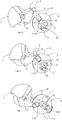
- FIGS. 5 to 9 For the sake of clarity, only the blocking device 8 and the coupling device 7 are shown, these two components of the door handle assembly 3 according to the invention appear to be sufficient to explain the operation of the door handle assembly 3 according to the invention.
- FIG. 5 shows a schematic side view of the locking device 8 in its rest position in which it is not activated.
- the coupling device 7 is arranged in rest position, for example, because the handle 4 is unconfirmed or because the locking device 8 no acceleration force acts as a result of a vehicle accident.
- the slot-shaped recess 14 and the radially extending recess 15 is oriented in the direction of the angled approach 12 of the coupling device 7 such that the angled Approach 12 when pivoting the coupling device 7 about the pivot axis 9 in the slot-shaped recess 14 of the locking device 8 can dip.
- the slot-shaped recess 14 of the locking device 8 is thus arranged in the rest position of the locking device 8 in the movement path 21 of the angled projection 12 of the pivoted coupling device 7.
- FIG. 6 This last movement is in FIG. 6 already completed.
- the locking device 8 is still in its rest position, whereas the coupling device 7 is pivoted about the pivot axis 9, which was due to a manual operation of the handle 4 by a user.
- pivoting the coupling device 7 about the pivot axis 9 of the angled projection 12 of the lever member 11 of the coupling device 8 dives into the slot-shaped recess 14 and in the recess 15 of the locking device 8, wherein the angled projection 12 of the lever member 11 in FIG. 6 on the wall 18 of the incision 15 is present.
- the handle 4 is half-operated, so that the closing assembly 5 is not yet released to open the door and the locking device 8 is still in the rest position.
- FIG. 7 the handle 4 is now fully operated and thus fully deflected, whereby the coupling device 7 is fully deflected and pivoted and thus the locking assembly 5 is released, so that the corresponding door 2 of the motor vehicle 1 can be opened.
- the coupling device 7 is rotated at most about the pivot axis 9, so that the angled lug 12 is now immersed not only in the slot-shaped recess 14 and in the recess 15 of the locking device 8, but the locking device 8 in a first blocking direction 19 (direction of the arrow 20 in FIG. 7 ) urges, whereby the locking device 8 is rotated counterclockwise about the axis of rotation 16 during normal operation of the handle 4 by a user.
- the coupling device 7 automatically enters the in FIG. 5 shown position, because an elastic spring element, which in the figures is not shown, provides for the provision of the coupling device 7 and applies a corresponding force, through which the coupling device to the starting position (see FIG. 5 ) is biased.
- a mechanical return element 22 is provided, which applies a locking device 8 urging the rest position force.
- the restoring element 22 comprises an elastic spring element 23, which is supported both on a stationary projection 24 of the handle support 6 and on a co-moving with the locking element 8 bearing element 25. Upon movement of the locking device 8 in the first or second blocking direction, the abutment element 25 moves relative to the projection 24 against the force of the elastic spring element 23rd
- FIGS. 5, 6 and 7 refer to positions of the coupling device 7 and the locking device 8, which are caused by a manual operation of the handle 4 by a user and by the interaction between the coupling device 7 and locking device 8 (thus representations which do not constitute a crash), which show FIGS. 8 and 9 Positions of both components during a vehicle accident.
- the locking device 8 moves depending on the direction in which the acceleration force acts.
- the acceleration force acts laterally on the door 2, on which the door handle assembly 3 is provided, in the direction of the vehicle interior (“inboard acceleration")
- FIG. 9 the acceleration force to the outside (“outboard acceleration") and the FIG.
- FIG. 8 applies analogously to the in FIG. 9 shown position of the locking device 8, but in this case from the rest position in the first blocking direction 19 which is opposite to the second blocking direction 26 is rotated.
- the locking device 8 is rotatable upon application of an acceleration force from the rest position to a maximum possible rotation angle about the rotation axis 16, whereby a sufficiently long Stellweg Suite for blocking the coupling device 7 and thus the handle 4 is present.
- the maximum possible rotation angle is +/- 270 °.
- FIG. 10 shows a perspective, enlarged view of the mechanical return element 22 of the door handle assembly 3.
- the mechanical return element 22 applies a force which urges the locking device 8 in the rest position.
- the mechanical return element 22 comprises the elastic spring element 23, with its two ends both on the stationary projection 24 of the handle support 6 and on which with the blocking element 8 mitbetaineden contact element 25 is supported with corresponding contact surfaces for the two ends of the spring element 23.
- the movement of the locking device 8 in the first or second blocking direction 19, 26 due to the application of an acceleration force in a vehicle accident moves the abutment member 25 relative to the lug 24 of the handle support 6 against the force of the elastic spring member 23 by one of the two ends of the spring element 23rd is deflected.
- a door handle assembly 3 is provided with a non-latching locking device 8, which is characterized by a secure activation and the handle 4 or the coupling device 7 safely blocked even in vibration or flutter due to the action of acceleration forces.
- the locking device 8 can rotate about its axis of rotation 16, so that bilateral pendulum movements, ie rotational movements in opposite directions, the locking device 8 are possible.
- the path of deflection of the locking device to move in the path of movement of the coupling device is carried out too low, which in practice led to situations in which the locking device after its deflection due to vibrations abruptly moved back and the coupling device was temporarily blocked, resulting in an undesirable operation of the closing arrangement and opening of the door.
- This danger is no longer in the present invention, because the locking device 8 has a larger blocking path upon activation, by the rotation about 270 ° about the rotation axis 16th given is. More blocking means at the same time more blocking time in one direction.
- the locking device 8 in two mutually opposite blocking directions 19, 26 movable, so that a blockage of the handle 4 and the coupling device 7 is given even in a bilateral pendulum or flutter of the locking device 8.
- the axis of rotation 16 of the locking device 8 is aligned substantially parallel to the pivot axis 9 of the coupling device 7.
- the angled shoulder 12 of the lever member 11 of the coupling device 7 moves into the recess 14 of the locking device 8 and rotates the locking device 8 in the normal operating mode of the handle 4, in which this is manually operated by a user.
- the locking device 8 designed as a swinging mass lock can be designed as a one-piece plastic part with a steel insert or with a material accumulation.
Landscapes
- Lock And Its Accessories (AREA)
Description
Die Erfindung richtet sich auf eine Türgriffanordnung für ein Kraftfahrzeug mit einem rahmenartigen Griffträger, einer manuell betätigbaren Handhabe, die an dem Griffträger zum Öffnen einer Tür oder Klappe des Kraftfahrzeugs durch einen Benutzer bewegbar gelagert ist, einer schwenkbar am Griffträger gelagerten Kopplungsvorrichtung, durch die eine Bewegung der Handhabe auf eine fahrzeugseitige Schließanordnung übertragbar ist, und einer als Massensperre dienenden Sperrvorrichtung, welche bewegbar an dem Griffträger gehalten ist und derart ausgebildet ist, dass sie bei Einwirkung einer Beschleunigungskraft aufgrund der Trägheit ihrer Masse aus einer Ruheposition, in welcher eine Betätigung der Handhabe möglich ist, in eine erste Blockierungsrichtung, in welcher eine Betätigung der Schließanordnung durch die Handhabe und/oder die Kopplungsvorrichtung blockiert ist, bewegbar ist.The invention is directed to a door handle assembly for a motor vehicle with a frame-like handle support, a manually operable handle, which is movably mounted on the handle support for opening a door or flap of the motor vehicle by a user, a pivotally mounted on the handle support coupling device by the movement the handle is transferable to a vehicle-side locking arrangement, and a locking device serving as a mass barrier, which is movably held on the handle carrier and is designed such that it is possible under the action of an accelerating force due to the inertia of their mass from a rest position in which actuation of the handle is, in a first blocking direction, in which an actuation of the closing arrangement is blocked by the handle and / or the coupling device is movable.
Derartige Türgriffanordnungen mit einer als Massensperre dienenden Sperrvorrichtung sollen verhindern, dass die bei einem Unfall auftretenden Beschleunigungskräfte zu einer Betätigung der Handhabe bzw. des Türgriffs führen und eine ungewollte Öffnung der Tür des Kraftfahrzeugs erfolgt, was erhebliche Risiken für einen Insassen des Fahrzeugs mit sich bringt. Bei üblichen Türgriffanordnungen für Kraftfahrzeuge sind nämlich die vom Benutzer zu betätigenden Griffbauteile mechanisch mit einer fahrzeugseitigen Schließanordnung (der eigentlichen Türverriegelung) gekoppelt. Die Bewegung des Türgriffs bzw. der Handhabe wird durch die Kopplungsvorrichtung auf die Schließanordnung übertragen und die Tür zur Öffnung freigegeben. Im Falle eines Unfalls wirken die Beschleunigungskräfte unter ungünstigen Bedingungen wie eine Betätigung des Griffbauteils durch einen Benutzer, da der Griff aufgrund der Massenträgheit in die Öffnungsrichtung beschleunigt werden kann. Bei einer Handhabe bzw. einem Türgriff ohne eine entsprechende Sperrvorrichtung würde die Bewegung des Griffbauteils relativ zu dem Fahrzeug zu einer Übertragung durch die mechanische Kopplungsvorrichtung auf die Schließanordnung im Fahrzeug und zu einer Freigabe der Tür führen. Beispielsszenarien für solche Situationen ist regelmäßig ein Seitenaufprall auf ein Hindernis oder ein anderes Fahrzeug. Eine solche als Massensperre dienende Sperrvorrichtung, die auch als Crashsperre bezeichnet wird, ist für Türgriffanordnungen aus dem Stand der Technik bekannt.Such door handle arrangements with a locking device serving as a mass barrier are intended to prevent the acceleration forces occurring in the event of an accident from leading to actuation of the handle or door handle and unintentional opening of the door of the motor vehicle, which entails considerable risks for an occupant of the vehicle. In conventional door handle assemblies for motor vehicles, namely, the user-operable gripping members are mechanically coupled to a vehicle-side locking assembly (the actual door lock). The movement of the door handle or the handle is transmitted by the coupling device to the closing arrangement and released the door to the opening. In the case of an accident, the acceleration forces under adverse conditions such as operation of the handle member by a user, since the handle can be accelerated due to the inertia in the opening direction. In a handle or a door handle without a corresponding locking device, the movement of the handle component would be relative to lead the vehicle to a transmission through the mechanical coupling device to the locking assembly in the vehicle and to a release of the door. Example scenarios for such situations is regularly a side impact on an obstacle or another vehicle. Such a mass-locking device, also referred to as a crash barrier, is known for door handle assemblies of the prior art.
Beispielsweise beschreibt die
Eine Türgriffanordnung der Eingangs bezeichneten Art mit einer in Form einer Crashsperre ausgebildeten Sperrvorrichtung ist zum Beispiel aus der
Solche bekannten Crashsperren können als Pendelmasse ausgeführt sein, so dass sich infolge der einwirkenden Kraft die Crashsperre beispielsweise in den Bewegungspfad der Handhabe verlagert und dadurch die Handhabe blockiert. Daneben sind auch Crashspeeren bekannt, die in einer Blockierungsposition einrasten und nach ihrer Aktivierung und Einrastung nur durch einen gezielten Eingriff in die Türgriffeinheit wieder deaktiviert werden können, so dass der Türgriff wieder im Normalbetrieb benutzt werden kann.Such known crash barriers can be designed as a pendulum mass, so that displaced as a result of the applied force, the crash barrier, for example, in the path of movement of the handle and thereby blocks the handle. In addition, crash spears are known, which engage in a blocking position and can be deactivated again after their activation and latching only by a targeted intervention in the door handle unit, so that the door handle can be used again in normal operation.
Bei aus dem Stand der Technik bekannten Türgriffanordnungen mit einer Massensperre bzw. einer Sperrvorrichtung, die bei Aktivierung nicht verrastet, sondern sich in ihre Normalbetriebsposition bzw. Ruheposition zurückbewegt bzw. pendelt, besteht der Nachteil, dass bei Einwirkung von Beschleunigungskräften die Sperrvorrichtung hin und her schwingen bzw. pendeln kann. Wie aus Unfallforschungsergebnissen bekannt ist, kann es bei einem Seitenaufprall zu alternierenden Beschleunigungskräften kommen, die zu einer Art Flattern der Türgriffanordnung, also einem Hin- und Herschwingen, führen. Dieses Flattern oder Schwingen ist dafür verantwortlich, dass die Sperrvorrichtung während ihres Pendelvorgangs in einer Position angeordnet sein kann, in welcher die Handhabe bzw. die Kopplungsvorrichtung trotz Crashfall nicht blockiert ist. Dies liegt daran, dass die bekannten Sperrvorrichtungen nur in einem relativ kleinen Sperrweg- oder Stellwegbereich, welcher eine Betätigung der als Umlenkhebel ausgebildeten Kopplungsvorrichtung bzw. der Handhabe blockiert, aktiv sind, so dass entweder bei starken und ausgeprägten Schwingungen oder bei lang andauernden Schwingungen infolge der Einwirkung von Beschleunigungskräften die Gefahr besteht, dass bei hin- und herschwingender bzw. pendelnder Sperrvorrichtung der Stellwegbereich nicht ausreichend lang ausgelegt ist, um eine Blockierung der Handhabe bzw. des Umlenkhebels sicher zu verhindern. Daher kann die Sperrvorrichtung im Crashfall während des Schwingvorgangs trotz ihrer Aktivierung eine Position einnehmen, in welcher sie die Handhabe bzw. den Umlenkhebel nicht blockiert. Von Nachteil ist ferner, dass die bekannten Türgriffanordnungen mit Crashsperre lediglich für eine ins Fahrzeuginnere gerichtete Beschleunigungskraft ausgelegt sind. Eine Beschleunigungskraft, welche in die entgegengesetzte Richtung gerichtet ist, wird nicht berücksichtigt, kann aber auch Einfluss auf eine unerwünschte Betätigung der Handhabe nehmen.In known from the prior art door handle assemblies with a mass lock or a locking device that does not lock when activated, but moves back to its normal operating position or rest position or oscillates, there is the disadvantage that swing under the action of acceleration forces the locking device back and forth or can commute. As from accident research results is known, it can come in a side impact to alternate acceleration forces, which lead to a kind of fluttering the door handle assembly, ie a swinging back and forth. This flapping or swinging is responsible for the fact that the locking device can be arranged during its pendulum operation in a position in which the handle or the coupling device is not blocked in the event of a crash. This is because the known locking devices are active only in a relatively small Sperrweg- or Stellwegbereich, which blocks an actuation of the coupling lever designed as a lever or the handle, so that either strong and pronounced vibrations or long-lasting vibrations due to The effect of acceleration forces there is a risk that, in the case of a reciprocating or oscillating locking device, the travel range is not designed to be sufficiently long in order to reliably prevent blocking of the handle or of the reversing lever. Therefore, in the event of a crash during the oscillation process, the locking device, despite its activation, can assume a position in which it does not block the handle or the lever. A further disadvantage is that the known door handle assemblies are designed with crash barrier only for a directed into the vehicle acceleration force. An acceleration force directed in the opposite direction is not taken into account but may also influence an undesired operation of the handle.
Der Erfindung liegt daher die Aufgabe zugrunde eine Lösung zu schaffen, die auf konstruktiv einfache Weise und kostengünstig eine Türgriffanordnung bereitstellt, bei der die Sperrvorrichtung auch bei alternierenden Beschleunigungskräften infolge eines Crashfalls zuverlässig und sicher die Handhabe bzw. die Kopplungsvorrichtung blockiert.The invention is therefore an object of the invention to provide a solution that provides a door handle assembly in a structurally simple manner and cost, in which the locking device reliably and safely blocks the handle or the coupling device even with alternating acceleration forces due to a crash.
Bei einer Türgriffanordnung der Eingangs bezeichneten Art wird die Aufgabe erfindungsgemäß dadurch gelöst, dass die Sperrvorrichtung bei Einwirkung einer Beschleunigungskraft aufgrund der Trägheit ihrer Masse aus der Ruheposition in eine zweite Blockierungsrichtung, in welcher eine Betätigung der Schließanordnung durch die Handhabe und/oder die Kopplungsvorrichtung blockiert ist, bewegbar ausgebildet ist, wobei die zweite Blockierungsrichtung der ersten Blockierungsrichtung entgegengesetzt ist.In a door handle assembly of the type described input, the object is achieved in that the locking device under the action of an acceleration force due to the inertia of their mass from the rest position in a second blocking direction, in which an actuation of the closure assembly is blocked by the handle and / or the coupling device, is designed to be movable, wherein the second blocking direction of the first blocking direction is opposite.
Vorteilhafte und zweckmäßige Ausgestaltungen und Weiterbildungen der Erfindung ergeben sich aus den Unteransprüchen.Advantageous and expedient refinements and developments of the invention will become apparent from the dependent claims.
Durch die Erfindung wird eine Türgriffanordnung eines Kraftfahrzeugs zur Verfügung gestellt, die sich durch eine funktionsgerechte Konstruktion auszeichnet und einen einfachen und kostengünstigen Aufbau aufweist. Dadurch, dass die Sperrvorrichtung bei Einwirkung einer Beschleunigungskraft aus der Ruheposition nicht nur in eine erste Blockierungsrichtung, sondern auch in eine zweite Blockierungsrichtung bewegbar ausgebildet ist, erhöht sich der Einsatzbereich der Sperrvorrichtung, denn diese ist nun nicht mehr nur bei einer in eine einzige, vorbestimmte Richtung wirkenden Beschleunigungskraft aktivierbar, sondern auch bei Einwirkung einer Beschleunigungskraft in eine zweite Richtung. Diese Eigenschaft der erfindungsgemäßen Sperrvorrichtung ist beispielsweise bei einem Fahrzeugunfall bzw. Crashfall von Vorteil, bei dem aufgrund der einwirkenden Beschleunigungskräfte ausgeprägte Schwingungsvorgänge vorherrschen, was zu einem Hin- und Herschwingen bzw. Pendeln bzw. Flattern der Sperrvorrichtung zwischen der Ruheposition und einer Blockierungsposition führt. Aufgrund der erfindungsgemäßen Möglichkeit, dass sich die Sperrvorrichtung in eine zweite Blockierungsrichtung im Crashfall bewegen kann, werden auch im Fall eines Zurückschwingens bzw. Pendelns der Sperrvorrichtung während eines Crashfalls die Handhabe und/oder die Kopplungsvorrichtung wirksam blockiert, denn die Sperrvorrichtung bewegt sich beim zurückpendeln aus einer ersten Blockierungsposition über die Ruheposition hinaus in eine zweite Blockierungsrichtung, wodurch die Sperrvorrichtung zu keinem Zeitpunkt in der Ruheposition verweilt, sondern die Ruheposition nur für eine minimale Zeitdauer durchlaufen wird.The invention provides a door handle assembly of a motor vehicle is available, which is characterized by a functional design and has a simple and inexpensive construction. Characterized in that the locking device is formed movable under the action of an acceleration force from the rest position not only in a first blocking direction, but also in a second blocking direction, the range of application of the locking device, because this is no longer only in a single, predetermined Direction acting acceleration force activated, but also when an accelerating force in a second direction. This property of the locking device according to the invention is for example in a vehicle accident or crash case of advantage in which prevail due to the applied acceleration forces pronounced vibration processes, resulting in a swinging back and forth or oscillation or fluttering of the locking device between the rest position and a blocking position. Due to the possibility according to the invention that the locking device can move in a second blocking direction in the event of a crash, the handle and / or the coupling device are effectively blocked even in the case of swinging back or oscillation of the locking device during a crash, because the locking device moves out when swinging back a first blocking position beyond the rest position in a second blocking direction, whereby the locking device at no time dwells in the rest position, but is passed through the rest position only for a minimum period of time.
Im Hinblick auf einen minimal vorzusehenden Einbauraum wirkt es sich günstig aus, wenn in Ausgestaltung der Erfindung die Sperrvorrichtung mittels einer Drehachse drehbar an dem Griffträger gelagert ist und wenn die Bewegung der Sperrvorrichtung in die erste und zweite Blockierungsrichtung eine Drehbewegung der Sperrvorrichtung ist. Dabei kann die Drehachse die Sperrvorrichtung in ihrem Mittelpunkt drehbar lagern, was sich ebenfalls günstig auf den vorzusehenden Einbauraum auswirkt.With regard to a minimal installation space to be provided, it is advantageous if, in an embodiment of the invention, the blocking device is rotatably mounted on the handle carrier by means of a rotation axis and if the movement of the blocking device in the first and second blocking direction is a rotary movement of the blocking device. In this case, the axis of rotation to store the locking device rotatably in its center, which also has a favorable effect on the installation space to be provided.
Um eine Blockierung der Handhabe bei entsprechend einwirkenden Beschleunigungskräften, die in Richtung des Fahrzeuginneren oder in entgegengesetzter Richtung wirken, zu realisieren, sieht die Erfindung in weiterer Ausgestaltung vor, dass die Sperrvorrichtung bei Einwirkung einer Beschleunigungskraft aus der Ruheposition heraus um einen maximal möglichen Drehwinkel um die Drehachse drehbar ist, wobei der Drehwinkel beispielsweise +/-90°, vorzugsweise +/-270° betragen kann. Dieser Bewegungsweg der Sperrvorrichtung bei ihrer Aktivierung ist ausreichend lang, so dass der Crashzustand, der durch die Einwirkung alternierender Beschleunigungskräfte und den damit einhergehenden Schwingungen bzw. Flatterbewegungen der Fahrzeugstruktur charakterisiert ist, beendet ist, noch bevor die Sperrvorrichtung aufgrund ihrer Federvorspannung wieder in ihre Ruheposition zurückbewegt wird.In order to realize a blocking of the handle with corresponding acting acceleration forces acting in the direction of the vehicle interior or in the opposite direction, the invention provides in a further embodiment that the locking device upon application of an acceleration force from the rest position to a maximum possible rotation angle to the Rotation axis is rotatable, wherein the rotation angle can be, for example, +/- 90 °, preferably +/- 270 °. This movement path of the locking device in its activation is sufficiently long, so that the crash state, which is characterized by the action of alternating acceleration forces and the associated oscillations or flutter movements of the vehicle structure, is completed even before the locking device moves back into its rest position due to their spring bias becomes.
Eine zunehmende Lebensdauer der Kraftfahrzeuge ist zu beobachten, wobei die Lebensdauer oftmals ein Alter von mehr als 10 Jahren übersteigt. Dabei wird die Sperrvorrichtung lange Zeit nicht betätigt, denn dies stellt nur den Ausnahmefall bei einem Fahrzeugunfall dar. Die Sperrvorrichtung ist Teil einer Türgriffanordnung und kann beispielsweise bei einem Außentürgriff vorgesehen sein, der Wettereinflüssen sowie Korrosion ausgesetzt ist. Bei den bekannten Türgriffanordnungen nach Art eines Außentürgriffs kann nicht garantiert werden, dass auch noch nach Jahren die gewünschte und einwandfreie Funktionalität der (bis dahin unbetätigten) Sperrvorrichtung vorhanden ist und die Fahrzeuginsassen optimalen Schutz bei einem Fahrzeugunfall genießen. Es ist daher eine weitere Aufgabe der vorliegenden Erfindung, die Funktionsfähigkeit der Türgriffanordnung und insbesondere der Sperrvorrichtung, die für lange Zeiträume so gut wie gar nicht betätigt wird, sicherzustellen. Dies wird im Rahmen der Erfindung dadurch erreicht, dass eine Schwenkbewegung der Kopplungsvorrichtung infolge einer manuellen Betätigung der Handhabe eine Bewegung der Sperrvorrichtung in eine der beiden Blockierungsrichtungen ohne Blockierung der Handhabe und/oder der Kopplungsvorrichtung bewirkt. Eine normale und damit manuelle Betätigung der Handhabe sowie die Einwirkung einer Beschleunigungskraft führen zu einer Drehbewegung der Sperrvorrichtung. Im ersten Fall wird die Handhabe zuerst manuell durch einen Benutzer betätigt, wobei die manuelle Betätigung der Handhabe dafür sorgt, dass sich die Sperrvorrichtung dreht. Bei jeder manuellen Betätigung der Handhabe wird zugleich auch die Sperrvorrichtung bewegt, wodurch sichergestellt ist, dass die drehbar gelagerte Sperrvorrichtung nicht mit der Zeit aufgrund von Witterungseinflüssen festklemmt oder sogar festkorrodiert ist. Die ständige Bewegung der Sperrvorrichtung sorgt vielmehr dafür, dass die Sperrvorrichtung ihre Funktion auch bei langer Lebensdauer beibehält. Im zweiten Fall erfolgt zunächst eine Drehbewegung der Sperrvorrichtung infolge einer Beschleunigungskraft, die auf die Sperrvorrichtung einwirkt. Aufgrund unterschiedlicher Massen wird bei Einwirkung einer Beschleunigungskraft zuerst die Sperrvorrichtung bewegt, bevor die Beschleunigungskraft dann eine Auslenkung der Handhabe bzw. der Kopplungsvorrichtung bewirkt. Da sich jedoch die Sperrvorrichtung bereits in eine Blockierungsrichtung bewegt, wird sie die Auslenkung der Kopplungsvorrichtung und der Handhabe blockieren.An increasing lifetime of the motor vehicles is to be observed, whereby the life span often exceeds an age of more than 10 years. In this case, the locking device is not operated for a long time, because this represents only the exceptional case of a vehicle accident. The locking device is part of a door handle assembly and can be provided for example in an exterior door handle, the weather and corrosion is exposed. In the known door handle assemblies on the type of exterior door handle can not be guaranteed that even after years, the desired and proper functionality of the (previously unactuated) locking device is present and enjoy the vehicle occupant optimal protection in a vehicle accident. It is therefore another task of the present invention, the operability of the door handle assembly and in particular the locking device, which is almost not operated for long periods to ensure. This is achieved in the context of the invention in that a pivoting movement of the coupling device as a result of a manual actuation of the handle causes a movement of the locking device in one of the two blocking directions without blocking the handle and / or the coupling device. A normal and thus manual operation of the handle and the action of an acceleration force lead to a rotational movement of the locking device. In the first case, the handle is first manually operated by a user, with manual operation of the handle causing the locking device to rotate. At each manual actuation of the handle at the same time the locking device is moved, which ensures that the rotatably mounted locking device is not clamped over time due to weather or even festkorroded. Rather, the constant movement of the locking device ensures that the locking device maintains its function even with a long service life. In the second case, first a rotational movement of the locking device takes place as a result of an acceleration force acting on the locking device. Due to different masses, the locking device is first moved under the action of an acceleration force, before the acceleration force then causes a deflection of the handle or the coupling device. However, since the locking device is already moving in a blocking direction, it will block the deflection of the coupling device and the handle.
Eine konstruktiv besonders günstige Möglichkeit der Realisierung einer Sperrvorrichtung, die bei manueller Betätigung der Handhabe eine Bewegung erfährt und bei Einwirkung einer Beschleunigungskraft infolge eines Fahrzeugunfalls eine Auslenkung der Handhabe blockiert, ist in Ausgestaltung der Erfindung dadurch gegeben, dass die Kopplungsvorrichtung ein gemeinsam mit ihr schwenkbares Hebelelement mit einem abgewinkelten Ansatz aufweist, der bei Verschwenkung der Kopplungsvorrichtung infolge einer manuellen Betätigung der Handhabe in eine - zum Beispiel schlitzförmig ausgebildete - Ausnehmung der Sperrvorrichtung eintaucht, wobei der abgewinkelte Ansatz bei weiterer, auslenkender Betätigung der Handhabe gegen die Wandung der schlitzförmigen Ausnehmung drückt und dabei die Sperrvorrichtung in eine der beiden Blockierungsrichtungen drängt. Die Bewegungskinematik der mit der Handhabe bewegungsgekoppelten Kopplungsvorrichtung wird dazu genutzt, an der Sperrvorrichtung direkt anzugreifen und diese aus der Ruheposition heraus in Richtung einer der beiden Blockierungsrichtungen zu bewegen. Bei normaler Betätigung der Handhabe wird also die Sperrvorrichtung mitbewegt, was beispielsweise in einem geringen Maße der Fall sein kann.A structurally particularly favorable possibility of realizing a locking device, which undergoes a movement upon manual actuation of the handle and blocks a deflection of the handle upon exposure to an acceleration force as a result of a vehicle accident, is given in an embodiment of the invention in that the coupling device is a pivotable together with her lever element having an angled approach, the pivoting of the Coupling device as a result of manual actuation of the handle in a - for example slot-shaped - recess of the locking device is immersed, wherein the angled approach presses in further, deflecting operation of the handle against the wall of the slot-shaped recess and thereby urges the locking device in one of the two blocking directions. The movement kinematics of the movement-coupled with the handle coupling device is used to directly attack the locking device and to move them from the rest position in the direction of one of the two blocking directions. In normal operation of the handle so the locking device is moved, which may be the case, for example, to a small extent.
Die Erfindung sieht in weiterer Ausgestaltung vor, dass die Sperrvorrichtung einen scheibenförmigen Blockierungskörper aufweist, in welchem die schlitzförmige Ausnehmung als ein in radialer Richtung verlaufender Einschnitt, in den der abgewinkelte Ansatz der Kopplungsvorrichtung einschwenken kann, ausgebildet ist. Durch diese Ausgestaltung kann der vorzusehende Bauraum für die Sperrvorrichtung insbesondere dann gering gehalten werden, wenn die Kopplungsvorrichtung um eine Schwenkachse schwenkbar an dem Griffträger gelagert ist, wobei die Drehachse der Sperrvorrichtung im Wesentlichen parallel zur Schwenkachse der Kopplungsvorrichtung ausgerichtet sein kann. Alternativ ist es denkbar, dass die Drehachse der Sperrvorrichtung in einem Winkel zu der Drehachse der Sperrvorrichtung ausgerichtet ist.The invention provides in a further embodiment that the locking device has a disk-shaped blocking body, in which the slot-shaped recess as a radially extending recess, in which the angled approach of the coupling device can pivot, is formed. By this configuration, the space to be provided for the locking device can be kept low in particular when the coupling device is mounted pivotably about a pivot axis on the handle carrier, wherein the axis of rotation of the locking device can be aligned substantially parallel to the pivot axis of the coupling device. Alternatively, it is conceivable that the axis of rotation of the locking device is aligned at an angle to the axis of rotation of the locking device.
Damit die Handhabe nach Einwirken von Beschleunigungskräften nicht weiter blockiert ist, ist es in Ausgestaltung der Erfindung von Vorteil, wenn ein mechanisches Rückstellelement vorgesehen ist, das eine die Sperrvorrichtung in die Ruheposition drängende Kraft aufbringt. Anders als bei bekannten Sperrvorrichtungen, die im Crashfall infolge der Einwirkung von Beschleunigungskräften einrasten und manuell erst wieder gelöst werden müssen, damit die Handhabe betätigbar ist, ist die Handhabe der erfindungsgemäßen Türgriffanordnung somit nach der Einwirkung von Beschleunigungskräften wieder verwendbar und betätigbar, da sich die Sperrvorrichtung wieder in der Ruheposition befindet.So that the handle is not blocked further after the action of acceleration forces, it is in an embodiment of the invention advantageous if a mechanical restoring element is provided which applies a locking device urging the rest position force. Unlike known locking devices that engage in the event of a crash due to the action of acceleration forces and manually must be solved again so that the handle is actuated, the handle of the door handle assembly according to the invention thus after the action of acceleration forces is reusable and actuated, since the locking device is in the rest position again.
Schließlich ist in Ausgestaltung der Erfindung vorgesehen, dass das mechanische Rückstellelement ein elastisches Federelement umfasst, das sowohl an einem ortsfesten Ansatz des Griffträgers als auch an einem sich mit dem Sperrelement mitbewegenden Anlageelement abgestützt ist, wobei sich bei Bewegung der Sperrvorrichtung in die erste oder zweite Blockierungsrichtung das Anlageelement relativ zu dem Ansatz gegen die Kraft des elastischen Federelements bewegt.Finally, it is provided in an embodiment of the invention that the mechanical restoring element comprises an elastic spring element which is supported both on a stationary approach of the handle support and on a mitbewegenden with the locking element contact element, wherein upon movement of the locking device in the first or second blocking direction moves the abutment member relative to the approach against the force of the elastic spring element.
Es versteht sich, dass die vorstehend genannten und nachstehenden noch zu erläuternden Merkmale nicht nur in der jeweils angegebenen Kombination, sondern auch in anderen Kombinationen oder in Alleinstellung verwendbar sind, ohne den Rahmen der vorliegenden Erfindung zu verlassen. Der Rahmen der Erfindung ist nur durch die Ansprüche definiert.It is understood that the features to be explained above and below can be used not only in the particular combination given, but also in other combinations or alone, without departing from the scope of the present invention. The scope of the invention is defined only by the claims.
Weitere Einzelheiten, Merkmale und Vorteile des Gegenstandes der Erfindung ergeben sich aus der nachfolgenden Beschreibung im Zusammenhang mit der Zeichnung, in der beispielhaft ein bevorzugtes Ausführungsbeispiel der Erfindung dargestellt ist. In der Zeichnung zeigt:
-
Figur 1 -
Figur 2 -
Figur 3 -
Figur 4Figur 3 -
Figur 5 -
Figur 6 -
Figur 7 -
Figur 8 -
Figur 9Figur 8 -
Figur 10
-
FIG. 1 a side view of a motor vehicle with a plurality of door handle assemblies according to the invention, -
FIG. 2 a perspective view of a door handle assembly according to the invention, -
FIG. 3 a perspective top view of a locking device of the door handle assembly, -
FIG. 4 a bottom perspective view of the locking deviceFIG. 3 . -
FIG. 5 a schematic side view of a coupling device and a locking device in the rest position, -
FIG. 6 a schematic side view of the coupling device and the locking device with a half-operated handle, -
FIG. 7 a schematic side view of the coupling device and the locking device with fully operated handle, -
FIG. 8 a schematic side view of the moving in a blocking direction locking device and the blocked coupling device, -
FIG. 9 a schematic side view of the locking device, in one of the inFIG. 8 is moved opposite blocking direction, and the blocked coupling device and -
FIG. 10 a perspective view of a mechanical return element of the door handle assembly.
In
In
Durch die mechanische Kopplungsvorrichtung 7 ist eine Bewegung der Handhabe 4 auf die entsprechende fahrzeugseitige Schließanordnung 5 übertragbar, um dadurch die entsprechende Tür 2 zu öffnen. Die als Massensperre dienende Sperrvorrichtung 8 kann bei Einwirkung einer Beschleunigungskraft ihre Position aus einer Ruheposition in eine Blockierungsposition verändern, wobei in der Ruheposition eine Betätigung der Handhabe 4 möglich ist, wohingegen in der Blockierungsposition die bewegbar an dem Griffträger 6 gehaltene Sperrvorrichtung 8 eine Betätigung der Schließanordnung 5 durch die Handhabe 4 und/oder eine Bewegung der Kopplungsvorrichtung 7 durch eine Betätigung der Handhabe 4 blockiert ist. Dabei kann die Sperrvorrichtung 8 in die Blockierungsposition durch eine Bewegung entweder in eine erste Blockierungsrichtung oder aber in eine zweite Blockierungsrichtung gelangen. Die zweite Blockierungsrichtung ist der ersten Blockierungsrichtung entgegengesetzt, wie nachstehend noch erläutert wird.By the
Wie beispielsweise aus den
Wie ferner den
Die Sperrvorrichtung 8 ist in den
In den
Diese zuletzt genannte Bewegung ist in
In
Sobald die Handhabe 4 nicht mehr betätigt ist, gelangt die Kopplungsvorrichtung 7 automatisch in die in
Während sich die
Die
Zusammenfassend wird mit der vorliegenden Erfindung eine Türgriffanordnung 3 mit einer nichtrastenden Sperrvorrichtung 8 bereitgestellt, die sich durch eine sichere Aktivierung auszeichnet und die Handhabe 4 bzw. die Kopplungsvorrichtung 7 auch bei Schwingungs- bzw. Flattervorgängen infolge der Einwirkung von Beschleunigungskräften sicher blockiert. Erfindungsgemäß wird dies dadurch ermöglicht, indem die Sperrvorrichtung 8 um ihre Drehachse 16 sich drehen kann, so dass beidseitige Pendelbewegungen, d.h. Drehbewegungen in entgegen gesetzte Richtungen, der Sperrvorrichtung 8 möglich sind. Bei den aus dem Stand der Technik bekannten Türgriffanordnungen ist der Weg der Auslenkung der Sperrvorrichtung, um sich in die Bewegungsbahn der Kopplungsvorrichtung zu bewegen, zu gering ausgeführt, was in der Praxis zu Situationen führte, in denen sich die Sperrvorrichtung nach ihrer Auslenkung infolge von Schwingungen schlagartig zurückbewegte und die Kopplungsvorrichtung zeitweise nicht blockiert war, was zu einer unerwünschten Betätigung der Schließanordnung und Öffnung der Tür führte. Diese Gefahr besteht bei der vorliegenden Erfindung nun nicht mehr, denn die Sperrvorrichtung 8 weist einen größeren Sperrweg bei Aktivierung auf, der durch die Drehbewegung um 270° um die Drehachse 16 gegeben ist. Mehr Sperrweg bedeutet gleichzeitig mehr Sperrzeit in eine Richtung. Darüber hinaus ist die Sperrvorrichtung 8 in zwei zueinander entgegengesetzte Blockierungsrichtungen 19, 26 bewegbar, so dass eine Blockierung der Handhabe 4 bzw. der Kopplungsvorrichtung 7 auch bei einem beidseitigen Pendeln bzw. Flattern der Sperrvorrichtung 8 gegeben ist. Gemäß der gezeigten Ausführungsform ist die Drehachse 16 der Sperrvorrichtung 8 im Wesentlichen parallel zur Schwenkachse 9 der Kopplungsvorrichtung 7 ausgerichtet. Um die Gängigkeit der Sperrvorrichtung 8 zu gewährleisten und somit ein Festsetzen der Sperrvorrichtung 8 zu vermeiden bewegt sich der abgewinkelte Absatz 12 des Hebelelements 11 der Kopplungsvorrichtung 7 in die Ausnehmung 14 der Sperrvorrichtung 8 hinein und verdreht die Sperrvorrichtung 8 im Normalbetriebsmodus der Handhabe 4, in welcher diese durch einen Benutzer manuell betätig ist. Die als pendelnde Massensperre ausgestaltete Sperrvorrichtung 8 kann als einteiliges Kunststoffteil mit Stahleinleger oder mit einer Materialanhäufung ausgebildet sein.In summary, with the present invention, a
Die vorstehend beschriebene Erfindung ist selbstverständlich nicht auf die beschriebene und dargestellte Ausführungsform beschränkt. Es ist ersichtlich, dass an der in der Zeichnung dargestellten Ausführungsform zahlreiche, dem Fachmann entsprechend der beabsichtigten Anwendung naheliegende Abänderungen vorgenommen werden können, ohne dass dadurch der Bereich der Erfindung verlassen wird. Dabei gehört zur Erfindung alles dasjenige, was in der Beschreibung enthalten und/oder in der Zeichnung dargestellt ist, einschließlich dessen, was abweichend von dem konkreten Ausführungsbeispiel für den Fachmann naheliegt.Of course, the invention described above is not limited to the described and illustrated embodiment. It will be appreciated that numerous modifications which are obvious to a person skilled in the art according to the intended application can be made to the embodiment shown in the drawing without departing from the scope of the invention. It belongs to the invention, all that which is contained in the description and / or shown in the drawing, including what, in deviation from the concrete embodiment obvious to those skilled.
Claims (9)
- A door handle arrangement for a motor vehicle, having:- a frame-like handle support (6),- a manually operated grip (4), which is mounted on the handle support (6) such that said grip can be moved by a user in order to open a door (2) or hatch of the motor vehicle (1),- a coupling device (7), which is mounted pivotably on the handle support (6) and by means of which a movement of the grip (4) can be transmitted to a closing arrangement (5) on the vehicle side, and- a locking device (8), which acts as a mass lock, is held movably on the handle support (6) and is formed such that it can be moved under the effect of an acceleration force, owing to the inertia of the mass thereof, from a rest position, in which operation of the grip (4) is possible, in a first blocking direction (19), in which operation of the closing arrangement (5) by means of the grip (4) and/or the coupling device (7) is blocked,characterised in that
the locking device (8) is formed such that it can be moved under the effect of an acceleration force, owing to the inertia of the mass thereof, from the rest position in a second blocking direction (26), in which operation of the closing arrangement (5) by means of the grip (4) and/or the coupling device (7) is blocked, wherein the second blocking direction (26) is oriented opposite to the first blocking direction (19). - The door handle arrangement according to Claim 1,
characterised in that
the locking device (8) is mounted rotatably on the handle support (6) by means of a rotation axis (16) and the movement of the locking device (8) in the first and second blocking directions (19, 26) is a rotary movement. - The door handle arrangement according to Claim 2,
characterised in that
the locking device (8) can be rotated about the rotation axis (16) by +/-270° out of the rest position under the effect of an acceleration force. - A door handle arrangement according to any one of the preceding claims,
characterised in that
a pivot movement of the coupling device (7) as a result of manual operation of the grip (4) effects a movement of the locking device (8) in one of the two blocking directions (19, 26) without blocking the grip (4) and/or the coupling device (7). - The door handle arrangement according to any one of the preceding claims,
characterised in that
the coupling device (7) has a lever element (11), which can be pivoted together with it and has an angled step (12), which passes into a slot-like recess (14) in the locking device (8) when the coupling device (7) pivots as a result of manual operation of the grip (4), wherein the angled step (12) presses against the wall (18) of the slot-like recess (14) on further, deflecting operation of the grip (4) and in the process displaces the locking device (8) in one of the two blocking directions (19, 26). - The door handle arrangement according to Claim 5,
characterised in that
the locking device (8) has a disc-shaped blocking body (13), in which the slot-like recess (14) is formed as a radial cut-out (15), into which the angled step (12) of the coupling device (7) can pivot. - The door handle arrangement according to any one of the preceding claims,
characterised in that
the coupling device (7) is mounted on the handle support (6) such that said coupling device can pivot about a pivot axis (9), wherein the rotation axis (16) of the locking device (8) is aligned substantially parallel to the pivot axis (9) of the coupling device (7). - The door handle device according to any one of the preceding claims,
characterised in that
a mechanical restoring element (22) is provided, which applies a force that displaces the locking device (8) into the rest position. - The door handle arrangement according to Claim 8,
characterised in that
the mechanical restoring element (22) comprises an elastic spring element (23), which is supported both on a stationary step (24) of the handle support (6) and on a rest element (25), which moves with the locking element (8), wherein the rest element (25) moves relative to the step (24) counter to the force of the elastic spring element (23) when the locking device (8) moves in the first or second blocking direction (19, 26).
Applications Claiming Priority (1)
| Application Number | Priority Date | Filing Date | Title |
|---|---|---|---|
| DE201310106610 DE102013106610A1 (en) | 2013-06-25 | 2013-06-25 | Door handle assembly for a motor vehicle |
Publications (4)
| Publication Number | Publication Date |
|---|---|
| EP2818615A2 EP2818615A2 (en) | 2014-12-31 |
| EP2818615A3 EP2818615A3 (en) | 2016-07-06 |
| EP2818615B1 true EP2818615B1 (en) | 2017-07-26 |
| EP2818615B2 EP2818615B2 (en) | 2020-08-12 |
Family
ID=50819651
Family Applications (1)
| Application Number | Title | Priority Date | Filing Date |
|---|---|---|---|
| EP14170327.2A Active EP2818615B2 (en) | 2013-06-25 | 2014-05-28 | Door handle assembly for a motor vehicle |
Country Status (3)
| Country | Link |
|---|---|
| US (1) | US9637956B2 (en) |
| EP (1) | EP2818615B2 (en) |
| DE (1) | DE102013106610A1 (en) |
Cited By (1)
| Publication number | Priority date | Publication date | Assignee | Title |
|---|---|---|---|---|
| US20250270857A1 (en) * | 2024-02-23 | 2025-08-28 | Witte Automotive Gmbh | Door handle |
Families Citing this family (12)
| Publication number | Priority date | Publication date | Assignee | Title |
|---|---|---|---|---|
| ITMI20112367A1 (en) * | 2011-12-22 | 2013-06-23 | Valeo Spa | SAFETY DEVICE FOR A VEHICLE DOOR HANDLE. |
| US9404292B2 (en) * | 2012-07-11 | 2016-08-02 | Huf North America Automotive Parts Mfg. Corp. | Vehicular door handle assembly with deployable latch connection |
| US9394729B2 (en) * | 2012-07-11 | 2016-07-19 | Huf North America Automotive Parts Mfg. Corp. | Vehicular door handle assembly with electrically deployable latch connection |
| KR101470248B1 (en) * | 2013-12-13 | 2014-12-15 | 현대자동차주식회사 | Door open preventing device in broad side collision |
| DE102015002053A1 (en) * | 2014-02-24 | 2015-08-27 | Magna Closures Inc. | Lock for a door of a motor vehicle |
| KR101628499B1 (en) * | 2014-10-17 | 2016-06-21 | 현대자동차주식회사 | Structure for preventing door opening at side impact and method for preventing door opening at side impact |
| US10000947B2 (en) * | 2016-02-24 | 2018-06-19 | Ford Global Technologies Llc | Auto-lock system for door window frame lateral retention |
| CN107905649B (en) * | 2017-11-10 | 2021-03-09 | 东风汽车有限公司 | Side door outer handle |
| FR3113080B1 (en) * | 2020-07-29 | 2022-06-24 | Akwel Vigo Spain Sl | Opening control device with reversible and irreversible inertial safety lock. |
| KR102777556B1 (en) * | 2020-09-04 | 2025-03-06 | 현대자동차 주식회사 | Door opening prevention structure in vehicle collision |
| US20240175299A1 (en) * | 2022-11-30 | 2024-05-30 | Hyundai Motor Company | Door opening and closing apparatus for prevention of door opening during collision |
| EP4592480A1 (en) * | 2024-01-25 | 2025-07-30 | Minebea AccessSolutions Italia S.p.A. | Vehicle door handle assembly |
Citations (5)
| Publication number | Priority date | Publication date | Assignee | Title |
|---|---|---|---|---|
| DE102008034649A1 (en) | 2008-07-25 | 2010-02-11 | Huf Hülsbeck & Fürst Gmbh & Co. Kg | External door handle for vehicle, has blocking element locking handle component based on inertness of mass of blocking element in case of crash, and housing-like cover covering blocking element at region of bearing and/or motion axle |
| EP2080857B1 (en) | 2008-01-18 | 2012-01-04 | Huf Hülsbeck & Fürst GmbH & Co. KG | External door grip assembly for vehicles |
| EP2138656B1 (en) | 2008-06-27 | 2013-01-16 | Huf Hülsbeck & Fürst GmbH & Co. KG | External door handle, in particular for vehicles |
| EP2743432A2 (en) | 2012-12-17 | 2014-06-18 | Huf Hülsbeck & Fürst GmbH & Co. KG | Handle for a closing device of a motor vehicle, with an inertial mass blocking element which takes accelerations acting from different directions into account |
| EP2811090A2 (en) | 2013-06-05 | 2014-12-10 | Huf Hülsbeck & Fürst GmbH & Co. KG | Door handle assembly for a motor vehicle |
Family Cites Families (14)
| Publication number | Priority date | Publication date | Assignee | Title |
|---|---|---|---|---|
| DE19929022C2 (en) | 1999-06-25 | 2001-06-07 | Huf Huelsbeck & Fuerst Gmbh | Outside door handle, in particular for vehicles |
| FR2871500B1 (en) * | 2004-06-09 | 2006-08-04 | Fabi Automobile Soc Par Action | MECHANISM FOR OPENING / CLOSING OF AUTOMOTIVE VEHICLE DOOR |
| US7481468B2 (en) * | 2006-10-25 | 2009-01-27 | Ford Global Technologies, Llc | Apparatus for blocking the movement of an inertially activated component |
| KR100792931B1 (en) * | 2006-12-12 | 2008-01-08 | 기아자동차주식회사 | Door opening prevention device in case of side collision of door out side handle |
| US8152209B2 (en) * | 2008-03-31 | 2012-04-10 | Illinois Tool Works Inc. | Delay apparatus for opening of vehicle door |
| IT1390596B1 (en) * | 2008-07-07 | 2011-09-09 | Valeo Spa | HANDLE WITH SAFETY DEVICE FOR VEHICLES |
| IT1394303B1 (en) * | 2009-05-21 | 2012-06-06 | Valeo Spa | DOOR HANDLE OF MOTOR VEHICLE |
| DE102009053553A1 (en) * | 2009-11-18 | 2011-05-19 | Huf Hülsbeck & Fürst Gmbh & Co. Kg | Safety handle |
| US8366159B2 (en) * | 2010-01-06 | 2013-02-05 | Ford Global Technologies, Llc | Multi-lever bi-directional inertia catch mechanism |
| DE202011106661U1 (en) * | 2011-10-12 | 2013-01-16 | Kiekert Ag | Actuating device for a motor vehicle door lock |
| DE102011085510A1 (en) * | 2011-10-31 | 2013-05-02 | BROSE SCHLIEßSYSTEME GMBH & CO. KG | An actuating device and method for actuating a locking device of a vehicle |
| US9404292B2 (en) * | 2012-07-11 | 2016-08-02 | Huf North America Automotive Parts Mfg. Corp. | Vehicular door handle assembly with deployable latch connection |
| JP6061092B2 (en) * | 2013-06-21 | 2017-01-18 | アイシン精機株式会社 | Vehicle door handle device |
| EP2942461B1 (en) * | 2014-05-05 | 2017-11-15 | U-Shin Italia S.p.A. | Vehicle latch activation system and motor vehicle comprising such vehicle latch activation system |
-
2013
- 2013-06-25 DE DE201310106610 patent/DE102013106610A1/en not_active Withdrawn
-
2014
- 2014-05-28 EP EP14170327.2A patent/EP2818615B2/en active Active
- 2014-06-17 US US14/307,065 patent/US9637956B2/en active Active
Patent Citations (5)
| Publication number | Priority date | Publication date | Assignee | Title |
|---|---|---|---|---|
| EP2080857B1 (en) | 2008-01-18 | 2012-01-04 | Huf Hülsbeck & Fürst GmbH & Co. KG | External door grip assembly for vehicles |
| EP2138656B1 (en) | 2008-06-27 | 2013-01-16 | Huf Hülsbeck & Fürst GmbH & Co. KG | External door handle, in particular for vehicles |
| DE102008034649A1 (en) | 2008-07-25 | 2010-02-11 | Huf Hülsbeck & Fürst Gmbh & Co. Kg | External door handle for vehicle, has blocking element locking handle component based on inertness of mass of blocking element in case of crash, and housing-like cover covering blocking element at region of bearing and/or motion axle |
| EP2743432A2 (en) | 2012-12-17 | 2014-06-18 | Huf Hülsbeck & Fürst GmbH & Co. KG | Handle for a closing device of a motor vehicle, with an inertial mass blocking element which takes accelerations acting from different directions into account |
| EP2811090A2 (en) | 2013-06-05 | 2014-12-10 | Huf Hülsbeck & Fürst GmbH & Co. KG | Door handle assembly for a motor vehicle |
Cited By (1)
| Publication number | Priority date | Publication date | Assignee | Title |
|---|---|---|---|---|
| US20250270857A1 (en) * | 2024-02-23 | 2025-08-28 | Witte Automotive Gmbh | Door handle |
Also Published As
| Publication number | Publication date |
|---|---|
| EP2818615A3 (en) | 2016-07-06 |
| EP2818615A2 (en) | 2014-12-31 |
| US20140375069A1 (en) | 2014-12-25 |
| DE102013106610A1 (en) | 2015-01-08 |
| EP2818615B2 (en) | 2020-08-12 |
| US9637956B2 (en) | 2017-05-02 |
Similar Documents
| Publication | Publication Date | Title |
|---|---|---|
| EP2818615B1 (en) | Door handle assembly for a motor vehicle | |
| EP2818614B1 (en) | Door handle assembly for a motor vehicle | |
| EP2813653B1 (en) | Door handle assembly for a motor vehicle | |
| EP2811090B1 (en) | Door handle assembly for a motor vehicle | |
| EP3126600B1 (en) | Actuating device for a motor vehicle lock | |
| EP3502384B2 (en) | Motor vehicle lock | |
| EP2633140B1 (en) | Motor vehicle door lock | |
| EP3126599B1 (en) | Actuating device for a motor vehicle lock | |
| WO2013053347A1 (en) | Actuation device for a motor vehicle door lock | |
| EP3027830B1 (en) | Motor vehicle door lock | |
| EP3445930A1 (en) | Motor vehicle door lock | |
| EP3087236B1 (en) | Motor vehicle door lock | |
| EP3803006B1 (en) | Door handle assembly for a motor vehicle | |
| DE102017216920A1 (en) | Door handle device for a door of a motor vehicle, door, motor vehicle | |
| EP3418478B1 (en) | Motor vehicle lock | |
| WO2017059836A1 (en) | Motor-vehicle door lock having a motion damper | |
| EP3935245B1 (en) | Motor vehicle lock | |
| EP2670934B1 (en) | Motor-vehicle lock | |
| DE102010012526A1 (en) | Foldable box for motor vehicle, has mass pendulum pivotably arranged at fixed axle, where mass pendulum, wheel axle, leg spring, damper element, and fixed axle are inserted for right-and left-side opening cover flaps | |
| WO2017036452A1 (en) | Motor vehicle door lock | |
| WO2016058653A1 (en) | Locking device for a door of a vehicle and method for operating a locking device | |
| EP3524758A1 (en) | Motor vehicle lock | |
| DE102018113918A1 (en) | Device for maintaining a locked state of a motor vehicle door and motor vehicle | |
| DE19732303A1 (en) | Car door lock blocking against unwanted opening |
Legal Events
| Date | Code | Title | Description |
|---|---|---|---|
| PUAI | Public reference made under article 153(3) epc to a published international application that has entered the european phase |
Free format text: ORIGINAL CODE: 0009012 |
|
| 17P | Request for examination filed |
Effective date: 20140528 |
|
| AK | Designated contracting states |
Kind code of ref document: A2 Designated state(s): AL AT BE BG CH CY CZ DE DK EE ES FI FR GB GR HR HU IE IS IT LI LT LU LV MC MK MT NL NO PL PT RO RS SE SI SK SM TR |
|
| AX | Request for extension of the european patent |
Extension state: BA ME |
|
| PUAL | Search report despatched |
Free format text: ORIGINAL CODE: 0009013 |
|
| AK | Designated contracting states |
Kind code of ref document: A3 Designated state(s): AL AT BE BG CH CY CZ DE DK EE ES FI FR GB GR HR HU IE IS IT LI LT LU LV MC MK MT NL NO PL PT RO RS SE SI SK SM TR |
|
| AX | Request for extension of the european patent |
Extension state: BA ME |
|
| RIC1 | Information provided on ipc code assigned before grant |
Ipc: E05B 85/10 20140101ALI20160601BHEP Ipc: E05B 77/06 20140101AFI20160601BHEP |
|
| STAA | Information on the status of an ep patent application or granted ep patent |
Free format text: STATUS: REQUEST FOR EXAMINATION WAS MADE |
|
| R17P | Request for examination filed (corrected) |
Effective date: 20161103 |
|
| RBV | Designated contracting states (corrected) |
Designated state(s): AL AT BE BG CH CY CZ DE DK EE ES FI FR GB GR HR HU IE IS IT LI LT LU LV MC MK MT NL NO PL PT RO RS SE SI SK SM TR |
|
| REG | Reference to a national code |
Ref country code: DE Ref legal event code: R079 Ref document number: 502014004719 Country of ref document: DE Free format text: PREVIOUS MAIN CLASS: E05B0077060000 Ipc: E05B0077020000 |
|
| GRAP | Despatch of communication of intention to grant a patent |
Free format text: ORIGINAL CODE: EPIDOSNIGR1 |
|
| STAA | Information on the status of an ep patent application or granted ep patent |
Free format text: STATUS: GRANT OF PATENT IS INTENDED |
|
| RIC1 | Information provided on ipc code assigned before grant |
Ipc: E05B 77/02 20140101AFI20170317BHEP Ipc: E05B 85/10 20140101ALI20170317BHEP Ipc: E05B 77/06 20140101ALI20170317BHEP |
|
| INTG | Intention to grant announced |
Effective date: 20170405 |
|
| GRAS | Grant fee paid |
Free format text: ORIGINAL CODE: EPIDOSNIGR3 |
|
| GRAA | (expected) grant |
Free format text: ORIGINAL CODE: 0009210 |
|
| STAA | Information on the status of an ep patent application or granted ep patent |
Free format text: STATUS: THE PATENT HAS BEEN GRANTED |
|
| AK | Designated contracting states |
Kind code of ref document: B1 Designated state(s): AL AT BE BG CH CY CZ DE DK EE ES FI FR GB GR HR HU IE IS IT LI LT LU LV MC MK MT NL NO PL PT RO RS SE SI SK SM TR |
|
| REG | Reference to a national code |
Ref country code: GB Ref legal event code: FG4D Free format text: NOT ENGLISH |
|
| REG | Reference to a national code |
Ref country code: CH Ref legal event code: EP |
|
| REG | Reference to a national code |
Ref country code: AT Ref legal event code: REF Ref document number: 912536 Country of ref document: AT Kind code of ref document: T Effective date: 20170815 |
|
| REG | Reference to a national code |
Ref country code: IE Ref legal event code: FG4D Free format text: LANGUAGE OF EP DOCUMENT: GERMAN |
|
| REG | Reference to a national code |
Ref country code: DE Ref legal event code: R096 Ref document number: 502014004719 Country of ref document: DE |
|
| REG | Reference to a national code |
Ref country code: NL Ref legal event code: MP Effective date: 20170726 |
|
| REG | Reference to a national code |
Ref country code: LT Ref legal event code: MG4D |
|
| PG25 | Lapsed in a contracting state [announced via postgrant information from national office to epo] |
Ref country code: NO Free format text: LAPSE BECAUSE OF FAILURE TO SUBMIT A TRANSLATION OF THE DESCRIPTION OR TO PAY THE FEE WITHIN THE PRESCRIBED TIME-LIMIT Effective date: 20171026 Ref country code: NL Free format text: LAPSE BECAUSE OF FAILURE TO SUBMIT A TRANSLATION OF THE DESCRIPTION OR TO PAY THE FEE WITHIN THE PRESCRIBED TIME-LIMIT Effective date: 20170726 Ref country code: LT Free format text: LAPSE BECAUSE OF FAILURE TO SUBMIT A TRANSLATION OF THE DESCRIPTION OR TO PAY THE FEE WITHIN THE PRESCRIBED TIME-LIMIT Effective date: 20170726 Ref country code: SE Free format text: LAPSE BECAUSE OF FAILURE TO SUBMIT A TRANSLATION OF THE DESCRIPTION OR TO PAY THE FEE WITHIN THE PRESCRIBED TIME-LIMIT Effective date: 20170726 Ref country code: HR Free format text: LAPSE BECAUSE OF FAILURE TO SUBMIT A TRANSLATION OF THE DESCRIPTION OR TO PAY THE FEE WITHIN THE PRESCRIBED TIME-LIMIT Effective date: 20170726 Ref country code: FI Free format text: LAPSE BECAUSE OF FAILURE TO SUBMIT A TRANSLATION OF THE DESCRIPTION OR TO PAY THE FEE WITHIN THE PRESCRIBED TIME-LIMIT Effective date: 20170726 |
|
| PG25 | Lapsed in a contracting state [announced via postgrant information from national office to epo] |
Ref country code: BG Free format text: LAPSE BECAUSE OF FAILURE TO SUBMIT A TRANSLATION OF THE DESCRIPTION OR TO PAY THE FEE WITHIN THE PRESCRIBED TIME-LIMIT Effective date: 20171026 Ref country code: LV Free format text: LAPSE BECAUSE OF FAILURE TO SUBMIT A TRANSLATION OF THE DESCRIPTION OR TO PAY THE FEE WITHIN THE PRESCRIBED TIME-LIMIT Effective date: 20170726 Ref country code: PL Free format text: LAPSE BECAUSE OF FAILURE TO SUBMIT A TRANSLATION OF THE DESCRIPTION OR TO PAY THE FEE WITHIN THE PRESCRIBED TIME-LIMIT Effective date: 20170726 Ref country code: IS Free format text: LAPSE BECAUSE OF FAILURE TO SUBMIT A TRANSLATION OF THE DESCRIPTION OR TO PAY THE FEE WITHIN THE PRESCRIBED TIME-LIMIT Effective date: 20171126 Ref country code: ES Free format text: LAPSE BECAUSE OF FAILURE TO SUBMIT A TRANSLATION OF THE DESCRIPTION OR TO PAY THE FEE WITHIN THE PRESCRIBED TIME-LIMIT Effective date: 20170726 Ref country code: GR Free format text: LAPSE BECAUSE OF FAILURE TO SUBMIT A TRANSLATION OF THE DESCRIPTION OR TO PAY THE FEE WITHIN THE PRESCRIBED TIME-LIMIT Effective date: 20171027 Ref country code: RS Free format text: LAPSE BECAUSE OF FAILURE TO SUBMIT A TRANSLATION OF THE DESCRIPTION OR TO PAY THE FEE WITHIN THE PRESCRIBED TIME-LIMIT Effective date: 20170726 |
|
| REG | Reference to a national code |
Ref country code: DE Ref legal event code: R026 Ref document number: 502014004719 Country of ref document: DE |
|
| PG25 | Lapsed in a contracting state [announced via postgrant information from national office to epo] |
Ref country code: CZ Free format text: LAPSE BECAUSE OF FAILURE TO SUBMIT A TRANSLATION OF THE DESCRIPTION OR TO PAY THE FEE WITHIN THE PRESCRIBED TIME-LIMIT Effective date: 20170726 Ref country code: DK Free format text: LAPSE BECAUSE OF FAILURE TO SUBMIT A TRANSLATION OF THE DESCRIPTION OR TO PAY THE FEE WITHIN THE PRESCRIBED TIME-LIMIT Effective date: 20170726 Ref country code: RO Free format text: LAPSE BECAUSE OF FAILURE TO SUBMIT A TRANSLATION OF THE DESCRIPTION OR TO PAY THE FEE WITHIN THE PRESCRIBED TIME-LIMIT Effective date: 20170726 |
|
| PLBI | Opposition filed |
Free format text: ORIGINAL CODE: 0009260 |
|
| PLAX | Notice of opposition and request to file observation + time limit sent |
Free format text: ORIGINAL CODE: EPIDOSNOBS2 |
|
| REG | Reference to a national code |
Ref country code: FR Ref legal event code: PLFP Year of fee payment: 5 |
|
| PG25 | Lapsed in a contracting state [announced via postgrant information from national office to epo] |
Ref country code: EE Free format text: LAPSE BECAUSE OF FAILURE TO SUBMIT A TRANSLATION OF THE DESCRIPTION OR TO PAY THE FEE WITHIN THE PRESCRIBED TIME-LIMIT Effective date: 20170726 Ref country code: IT Free format text: LAPSE BECAUSE OF FAILURE TO SUBMIT A TRANSLATION OF THE DESCRIPTION OR TO PAY THE FEE WITHIN THE PRESCRIBED TIME-LIMIT Effective date: 20170726 Ref country code: SM Free format text: LAPSE BECAUSE OF FAILURE TO SUBMIT A TRANSLATION OF THE DESCRIPTION OR TO PAY THE FEE WITHIN THE PRESCRIBED TIME-LIMIT Effective date: 20170726 Ref country code: SK Free format text: LAPSE BECAUSE OF FAILURE TO SUBMIT A TRANSLATION OF THE DESCRIPTION OR TO PAY THE FEE WITHIN THE PRESCRIBED TIME-LIMIT Effective date: 20170726 |
|
| 26 | Opposition filed |
Opponent name: WITTE AUTOMOTIVE GMBH Effective date: 20180426 |
|
| PG25 | Lapsed in a contracting state [announced via postgrant information from national office to epo] |
Ref country code: SI Free format text: LAPSE BECAUSE OF FAILURE TO SUBMIT A TRANSLATION OF THE DESCRIPTION OR TO PAY THE FEE WITHIN THE PRESCRIBED TIME-LIMIT Effective date: 20170726 |
|
| PLBB | Reply of patent proprietor to notice(s) of opposition received |
Free format text: ORIGINAL CODE: EPIDOSNOBS3 |
|
| PG25 | Lapsed in a contracting state [announced via postgrant information from national office to epo] |
Ref country code: MT Free format text: LAPSE BECAUSE OF FAILURE TO SUBMIT A TRANSLATION OF THE DESCRIPTION OR TO PAY THE FEE WITHIN THE PRESCRIBED TIME-LIMIT Effective date: 20170726 |
|
| REG | Reference to a national code |
Ref country code: CH Ref legal event code: PL |
|
| GBPC | Gb: european patent ceased through non-payment of renewal fee |
Effective date: 20180528 |
|
| REG | Reference to a national code |
Ref country code: BE Ref legal event code: MM Effective date: 20180531 |
|
| PG25 | Lapsed in a contracting state [announced via postgrant information from national office to epo] |
Ref country code: MC Free format text: LAPSE BECAUSE OF FAILURE TO SUBMIT A TRANSLATION OF THE DESCRIPTION OR TO PAY THE FEE WITHIN THE PRESCRIBED TIME-LIMIT Effective date: 20170726 |
|
| REG | Reference to a national code |
Ref country code: IE Ref legal event code: MM4A |
|
| PG25 | Lapsed in a contracting state [announced via postgrant information from national office to epo] |
Ref country code: CH Free format text: LAPSE BECAUSE OF NON-PAYMENT OF DUE FEES Effective date: 20180531 Ref country code: LI Free format text: LAPSE BECAUSE OF NON-PAYMENT OF DUE FEES Effective date: 20180531 |
|
| PG25 | Lapsed in a contracting state [announced via postgrant information from national office to epo] |
Ref country code: LU Free format text: LAPSE BECAUSE OF NON-PAYMENT OF DUE FEES Effective date: 20180528 |
|
| PG25 | Lapsed in a contracting state [announced via postgrant information from national office to epo] |
Ref country code: IE Free format text: LAPSE BECAUSE OF NON-PAYMENT OF DUE FEES Effective date: 20180528 Ref country code: GB Free format text: LAPSE BECAUSE OF NON-PAYMENT OF DUE FEES Effective date: 20180528 |
|
| PG25 | Lapsed in a contracting state [announced via postgrant information from national office to epo] |
Ref country code: BE Free format text: LAPSE BECAUSE OF NON-PAYMENT OF DUE FEES Effective date: 20180531 |
|
| PG25 | Lapsed in a contracting state [announced via postgrant information from national office to epo] |
Ref country code: TR Free format text: LAPSE BECAUSE OF FAILURE TO SUBMIT A TRANSLATION OF THE DESCRIPTION OR TO PAY THE FEE WITHIN THE PRESCRIBED TIME-LIMIT Effective date: 20170726 |
|
| PG25 | Lapsed in a contracting state [announced via postgrant information from national office to epo] |
Ref country code: PT Free format text: LAPSE BECAUSE OF FAILURE TO SUBMIT A TRANSLATION OF THE DESCRIPTION OR TO PAY THE FEE WITHIN THE PRESCRIBED TIME-LIMIT Effective date: 20170726 Ref country code: HU Free format text: LAPSE BECAUSE OF FAILURE TO SUBMIT A TRANSLATION OF THE DESCRIPTION OR TO PAY THE FEE WITHIN THE PRESCRIBED TIME-LIMIT; INVALID AB INITIO Effective date: 20140528 |
|
| PG25 | Lapsed in a contracting state [announced via postgrant information from national office to epo] |
Ref country code: MK Free format text: LAPSE BECAUSE OF NON-PAYMENT OF DUE FEES Effective date: 20170726 Ref country code: CY Free format text: LAPSE BECAUSE OF FAILURE TO SUBMIT A TRANSLATION OF THE DESCRIPTION OR TO PAY THE FEE WITHIN THE PRESCRIBED TIME-LIMIT Effective date: 20170726 |
|
| PUAH | Patent maintained in amended form |
Free format text: ORIGINAL CODE: 0009272 |
|
| STAA | Information on the status of an ep patent application or granted ep patent |
Free format text: STATUS: PATENT MAINTAINED AS AMENDED |
|
| PG25 | Lapsed in a contracting state [announced via postgrant information from national office to epo] |
Ref country code: AL Free format text: LAPSE BECAUSE OF FAILURE TO SUBMIT A TRANSLATION OF THE DESCRIPTION OR TO PAY THE FEE WITHIN THE PRESCRIBED TIME-LIMIT Effective date: 20170726 |
|
| 27A | Patent maintained in amended form |
Effective date: 20200812 |
|
| AK | Designated contracting states |
Kind code of ref document: B2 Designated state(s): AL AT BE BG CH CY CZ DE DK EE ES FI FR GB GR HR HU IE IS IT LI LT LU LV MC MK MT NL NO PL PT RO RS SE SI SK SM TR |
|
| REG | Reference to a national code |
Ref country code: DE Ref legal event code: R102 Ref document number: 502014004719 Country of ref document: DE |
|
| REG | Reference to a national code |
Ref country code: AT Ref legal event code: MM01 Ref document number: 912536 Country of ref document: AT Kind code of ref document: T Effective date: 20190528 |
|
| PG25 | Lapsed in a contracting state [announced via postgrant information from national office to epo] |
Ref country code: AT Free format text: LAPSE BECAUSE OF NON-PAYMENT OF DUE FEES Effective date: 20190528 |
|
| PGFP | Annual fee paid to national office [announced via postgrant information from national office to epo] |
Ref country code: FR Payment date: 20210525 Year of fee payment: 8 |
|
| PG25 | Lapsed in a contracting state [announced via postgrant information from national office to epo] |
Ref country code: FR Free format text: LAPSE BECAUSE OF NON-PAYMENT OF DUE FEES Effective date: 20220531 |
|
| P01 | Opt-out of the competence of the unified patent court (upc) registered |
Effective date: 20230507 |
|
| PGFP | Annual fee paid to national office [announced via postgrant information from national office to epo] |
Ref country code: DE Payment date: 20250531 Year of fee payment: 12 |