EP2818291A1 - Rigid core for forming tire - Google Patents
Rigid core for forming tire Download PDFInfo
- Publication number
- EP2818291A1 EP2818291A1 EP13764133.8A EP13764133A EP2818291A1 EP 2818291 A1 EP2818291 A1 EP 2818291A1 EP 13764133 A EP13764133 A EP 13764133A EP 2818291 A1 EP2818291 A1 EP 2818291A1
- Authority
- EP
- European Patent Office
- Prior art keywords
- tire
- core
- thermal expansion
- inward
- outward
- Prior art date
- Legal status (The legal status is an assumption and is not a legal conclusion. Google has not performed a legal analysis and makes no representation as to the accuracy of the status listed.)
- Granted
Links
Images



Classifications
-
- B—PERFORMING OPERATIONS; TRANSPORTING
- B29—WORKING OF PLASTICS; WORKING OF SUBSTANCES IN A PLASTIC STATE IN GENERAL
- B29D—PRODUCING PARTICULAR ARTICLES FROM PLASTICS OR FROM SUBSTANCES IN A PLASTIC STATE
- B29D30/00—Producing pneumatic or solid tyres or parts thereof
- B29D30/06—Pneumatic tyres or parts thereof (e.g. produced by casting, moulding, compression moulding, injection moulding, centrifugal casting)
- B29D30/0601—Vulcanising tyres; Vulcanising presses for tyres
- B29D30/0661—Rigid cores therefor, e.g. annular or substantially toroidal cores
-
- B—PERFORMING OPERATIONS; TRANSPORTING
- B29—WORKING OF PLASTICS; WORKING OF SUBSTANCES IN A PLASTIC STATE IN GENERAL
- B29C—SHAPING OR JOINING OF PLASTICS; SHAPING OF MATERIAL IN A PLASTIC STATE, NOT OTHERWISE PROVIDED FOR; AFTER-TREATMENT OF THE SHAPED PRODUCTS, e.g. REPAIRING
- B29C33/00—Moulds or cores; Details thereof or accessories therefor
- B29C33/38—Moulds or cores; Details thereof or accessories therefor characterised by the material or the manufacturing process
-
- B—PERFORMING OPERATIONS; TRANSPORTING
- B29—WORKING OF PLASTICS; WORKING OF SUBSTANCES IN A PLASTIC STATE IN GENERAL
- B29D—PRODUCING PARTICULAR ARTICLES FROM PLASTICS OR FROM SUBSTANCES IN A PLASTIC STATE
- B29D30/00—Producing pneumatic or solid tyres or parts thereof
- B29D30/06—Pneumatic tyres or parts thereof (e.g. produced by casting, moulding, compression moulding, injection moulding, centrifugal casting)
- B29D30/0601—Vulcanising tyres; Vulcanising presses for tyres
- B29D30/0606—Vulcanising moulds not integral with vulcanising presses
-
- B—PERFORMING OPERATIONS; TRANSPORTING
- B29—WORKING OF PLASTICS; WORKING OF SUBSTANCES IN A PLASTIC STATE IN GENERAL
- B29D—PRODUCING PARTICULAR ARTICLES FROM PLASTICS OR FROM SUBSTANCES IN A PLASTIC STATE
- B29D30/00—Producing pneumatic or solid tyres or parts thereof
- B29D30/06—Pneumatic tyres or parts thereof (e.g. produced by casting, moulding, compression moulding, injection moulding, centrifugal casting)
- B29D30/08—Building tyres
- B29D30/10—Building tyres on round cores, i.e. the shape of the core is approximately identical with the shape of the completed tyre
- B29D30/12—Cores
-
- B—PERFORMING OPERATIONS; TRANSPORTING
- B29—WORKING OF PLASTICS; WORKING OF SUBSTANCES IN A PLASTIC STATE IN GENERAL
- B29C—SHAPING OR JOINING OF PLASTICS; SHAPING OF MATERIAL IN A PLASTIC STATE, NOT OTHERWISE PROVIDED FOR; AFTER-TREATMENT OF THE SHAPED PRODUCTS, e.g. REPAIRING
- B29C33/00—Moulds or cores; Details thereof or accessories therefor
- B29C33/02—Moulds or cores; Details thereof or accessories therefor with incorporated heating or cooling means
-
- B—PERFORMING OPERATIONS; TRANSPORTING
- B29—WORKING OF PLASTICS; WORKING OF SUBSTANCES IN A PLASTIC STATE IN GENERAL
- B29K—INDEXING SCHEME ASSOCIATED WITH SUBCLASSES B29B, B29C OR B29D, RELATING TO MOULDING MATERIALS OR TO MATERIALS FOR MOULDS, REINFORCEMENTS, FILLERS OR PREFORMED PARTS, e.g. INSERTS
- B29K2995/00—Properties of moulding materials, reinforcements, fillers, preformed parts or moulds
- B29K2995/0012—Properties of moulding materials, reinforcements, fillers, preformed parts or moulds having particular thermal properties
-
- B—PERFORMING OPERATIONS; TRANSPORTING
- B29—WORKING OF PLASTICS; WORKING OF SUBSTANCES IN A PLASTIC STATE IN GENERAL
- B29L—INDEXING SCHEME ASSOCIATED WITH SUBCLASS B29C, RELATING TO PARTICULAR ARTICLES
- B29L2030/00—Pneumatic or solid tyres or parts thereof
Definitions
- thermal expansion in a cross-sectional direction ⁇ 1 and thermal expansion in a radial direction ⁇ 2 occur as the thermal expansion.
- the thermal expansion in the cross-sectional direction ⁇ 1 is the thermal expansion that causes the outer surface (as) to expand so as to swell outward in a meridional cross section of the core body (a1).
- the thermal expansion in the radial direction ⁇ 2 is the thermal expansion that causes the ring-shaped core body (a1) to expand so as to increase a diameter thereof outwardly in a tire radial di rection around a ti re axis (i). Consequently, as conceptually shown in FIG.
- Patent document 1 Japanese Unexamined Patent Application No. 2006-160236
- the metal material having a high coefficient of thermal expansion can be used to increase the expansion in the region to be subjected to small expansion due to the radial thermal expansion (namely, the region disposed more radially inward than the maximum width position P0).
- the metal material having a low coefficient of thermal expansion can be used to decrease the expansion in the region to be subjected to large expansion due to the radial thermal expansion (namely, the region disposed more radially outward than the maximum width position P0).
- the tire forming surface S includes a tread forming surface region Sa for forming an inner surface of a tread region (ta) of the green tire (t), a sidewall forming surface region sb for forming an inner surface of a sidewall region (tb), and a bead forming surface region Sc for forming an inner surface of a bead region (tc).
- the tire forming surface S is to be formed in approximately the same shape as an inner surface shape of the finished tire.
- a ratio ( ⁇ i/ ⁇ o) of the coefficients of thermal expansion ⁇ i and ⁇ o is preferably not less than 1.07, more preferably not less than 1.34.
- the present embodiment illustrates the case where the guide means 20A is made of a combination of a guide groove 22a that is buried in one divided surface 21 and extends in the tire axis direction, and a guide rib 22b that is projected on another divided surface 21 and is guided along the guide groove 22a (hereinafter referred to as "a pair of guides 22) .
- FIG. 3 illustrates the case where the guide groove 22a and the guide rib 22b are respectively a so-called dovetail groove and a so-called dovetail tenon each having a trapezoidal cross-secti on.
- the guide means 20A needs only a single pair of guides 22.
- the coupling means 20 includes a holder 20B.
- the holder 20B has, for example, a U-shaped cross section extending along a surface of the inner cavity region 4 (in some cases referred to as "inner hole surface 4s") and makes the inner hole surfaces 4s of the inward divided core pieces 10i and the inner hole surfaces 4s of outward divided core pieces 10o flush.
- the holder 20B and the divided core pieces 10i and 10o are coupled to each other by a screw fitting.
- the holder 20B does not inhibit the effects of the present invention because when the divided core pieces 10i and 10o are subjected to radial thermal expansion ⁇ 2, both can be radially extended and deformed due to the thermal expansion ⁇ 2.
- core bodi es for forming a pneumatic tire of a tire size 195/65R15 were produced experimentally based on specifications presented in Table 2.
- the individual core bodies were subjected to a temperature rise from normal temperature of 20°C to 150°C so as to be subjected to thermal expansion, and outer shapes of the individual core bodies were respectively measured using a laser displacement meter.
- FIGs. 9(A) to 9(C) respectively conceptually show structures of the core body.
- the metal materials MA to ME used in the individual regions are presented in Table 1.
- Table 2 Comp. Ex. 1.
- Comp. Ex. 2 Ex. 1 Ex. 2 Ex. 3 Ex. 4 Ex. 5 Core Body Internal structure
- FIG. 9(A) FIG. 9(A) FIG. 9(B) FIG. 9(B) FIG. 9(B) FIG. 9(B) FIG. 9(B) FIG.
- Examples are capable of uniformalizing the vulcanizing pressure applied to the green tire during the vulcanization molding so as to suppress the occurrence of air space within the tire, thereby improving the quality of the tire.
Landscapes
- Engineering & Computer Science (AREA)
- Mechanical Engineering (AREA)
- Manufacturing & Machinery (AREA)
- Moulds For Moulding Plastics Or The Like (AREA)
- Heating, Cooling, Or Curing Plastics Or The Like In General (AREA)
Abstract
Description
- The present invention relates to a rigid core for forming a ti re whi ch is capable of uni formal i zi ng thermal expansi on of a core body during vulcanization molding so as to improve quality of a finished tire.
- In recent years, a method for forming a ti re usi ng a ri gi d core (a) including a core body (a1) having a tire forming surface (as) on an outer surface thereof as shown in
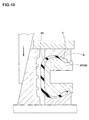
FIG. 10 (hereinafter generally referred to as "core method") has been proposed to enhance accuracy in forming a pneumatic tire (refer to, for example, patent document 1). - with the core method, tire structural members, such as a carcass ply, a belt ply, a sidewall rubber, and a tread rubber, are sequentially stuck one upon another on the tire forming surface (as) so as to form a green tire (t) having approximately the same shape as a finished tire (corresponding to a tire product after being subjected to vulcanization). The green tire (t), together with the rigid core (a), is then loaded into a vulcanization mold (b) so as to subject the green tire (t) to vulcanization molding between the core body (a1) as an inner mold and the vulcanization mold (b) as an outer mold.
- on this occasion, the core body (a1) is heated in the vulcanization mold (b) from a low temperature state of 100°C or below to a high temperature state of approximately 150°C in order to subject the green tire (t) to heat vulcanization. Therefore, thermal expansion occurs in the core body (a1), and a shape dimension of the core body (a1) varies in the vulcanization mold (b).
- As conceptually shown in
FIG. 11(A) , thermal expansion in a cross-sectional direction ε1 and thermal expansion in a radial direction ε2 occur as the thermal expansion. The thermal expansion in the cross-sectional direction ε1 is the thermal expansion that causes the outer surface (as) to expand so as to swell outward in a meridional cross section of the core body (a1). The thermal expansion in the radial direction ε2 is the thermal expansion that causes the ring-shaped core body (a1) to expand so as to increase a diameter thereof outwardly in a tire radial di rection around a ti re axis (i). Consequently, as conceptually shown inFIG. 11(B) , expansion (d) varies across the cross section of the core body (a1). In particular, the thermal expansion in the radial direction ε2 is added to the thermal expansion in the cross-sectional direction ε1 so as to increase the expansion (d) on a side closer to a tread than a maximum width position P0 of the ti re forming surface (as) (namely, on a radially outside). In contrast, the thermal expansion in the radial direction ε2 is subtracted from the thermal expansion in the cross-sectional direction ε1 so as to decrease the expansion (d) on a side closer to a bead than the maximum width position P0 (namely, on a radially inside). - The vulcanization mold (b) is controlled at a constant temperature (for example, approximately 160°C) over the whole vulcanization process. Therefore, the shape dimension of a cavity surface (bs) of the vulcanization mold (b) remains almost unchanged. The nonuniformity of the expansion (d) of the core body (a1) causes nonuniformity of vulcanizing pressure applied to the green tire (t) (pressing force applied to the cavity surface (bs)). That is, the vulcanizing pressure becomes high on the tread side and low on the bead side. This leads to the problem that the quality of the tire is deteriorated due to insufficient vulcanization on the bead side subjected to the low vulcanizing pressure, and due to difficulties in discharging air remaining within the tire.
- Patent document 1: Japanese Unexamined Patent Application No.
2006-160236 - It is an object of the present invention to provide a rigid core for forming a tire which suppresses the nonuniformity of the thermal expansion of the core body so as to uniformalize the vulcanizing pressure applied to the green tire, thus improving the quality of the tire.
- To achieve the above-mentioned object, the invention according to
claim 1, a rigid core for forming a tire comprises a core body provided on an outer surface thereof with a tire forming surface configured to form thereon a green tire by sequentially sticking tire structural members, the rigid core being configured to be loaded together with the green tire formed on the tire forming surface into a vulcanization mold so as to subject the green tire to vulcanization molding between the vulcanization mold and the core body. The core body comprises a plurality of divided core pieces configured to be di vi ded inward and outward in a tire radial direction at a tire radial position P including a maximum width position P0 at whi ch the ti re forming surface bul ges most outward i n a ti re axi al direction. An outward divided core piece disposed more outward in the tire radial direction than the maximum width position P0, and an inward divided core piece disposed more inward in the tire radial di recti on than the maxi mum wi dth posi ti on P0 are respectively formed of metal materi al s di fferent from each other in coefficient of thermal expansion. And a coefficient of thermal expansion of the inward divided core piece is higher than a coefficient of thermal expansion of the outward divided core piece. - According to
claim 2, the core body comprises three or more divided core pieces respectively formed of metal materials different from one another in coefficient of thermal expansion, and the divided core pieces have a higher coefficient of thermal expansion as being disposed more inward in the tire radial direction. - with the present invention as described above, the core body is made up of the plurality of divided core pieces to be divided inward and outward in the tire radial direction. The divided core piece disposed more outward in the tire radial direction than the maximum width position P0, and the divided core piece disposed more inward in the ti re radial direction than the maxi mum wi dth posi ti on P0 are respectively formed of metal materials different from each other in coefficient of thermal expansion. The coefficient of thermal expansion of the divided core piece disposed more inward in the tire radial direction is higher than the coefficient of thermal expansi on of the di vi ded core pi ece di sposed more outward in the tire radial direction.
- Accordingly, the metal material having a high coefficient of thermal expansion can be used to increase the expansion in the region to be subjected to small expansion due to the radial thermal expansion (namely, the region disposed more radially inward than the maximum width position P0). In contrast, the metal material having a low coefficient of thermal expansion can be used to decrease the expansion in the region to be subjected to large expansion due to the radial thermal expansion (namely, the region disposed more radially outward than the maximum width position P0).
- This contributes to minimizing the nonuniformity of expansi on over the enti re
core body 2. Consequently, the vulcanizing pressure applied to the green tire during the vulcanization molding can be uniformalized to suppress, for example, insufficient vulcanization to be caused in a regi on subjected to low vulcanizing pressure, and occurrence of air space within the tire, thereby improving the quality of the tire. -
-
FIG. 1 is a cross-sectional view showing an embodiment of a rigid core for forming a tire according to the present invention; -
FIGs. 2 (A) and 2 (B) are respectively a side view and a perspective view of a core body; -
FIG. 3 is an explanatory drawing showing an embodiment of coupling means for coupling divided core pieces to each other; -
FIG. 4 is an explanatory drawing showing another embodiment of the coupling means; -
FIG. 5 is a cross-sectional view showing another embodiment of the core body; -
FIG. 6 is an explanatory drawing showing another embodiment of the coupling means for coupling the divided core pieces to each other; -
FIG. 7 is an explanatory drawing showing still another embodiment of the coupling means; -
FIG. 8 is a cross-sectional view showing gap evaluation positions presented in Table 2; -
FIGs. 9(A) to 9(C) are conceptual drawings respectively showing structures of the core body presented in Table 2; -
FIG. 10 is a cross-sectional view for explaining a core method; and -
FIGs. 11(A) and 11(B) are conceptual drawings for explaining problems in a conventional rigid core. - An embodiment of the present invention is described in detail below.
- As shown in
FIG. 1 , arigid core 1 of the present embodiment includes anannular core body 2 having a tire forming surface s on an outer surface thereof. Tire structural members, such as a carcass ply, a belt ply, a sidewall rubber, and a tread rubber, are to be sequentially stuck one upon another on the tire forming surface S so as to form a green tire (t) having approximately the same shape as a finished tire. In a similar manner to conventional ones, the green tire (t) is to be loaded together with therigid core 1 into a vulcanization mold (b) so as to be subjected to vulcanization molding while being heated and pressurized between thecore body 2 as an inner mold and the vulcanization mold (b) as an outer mold. - The tire forming surface S includes a tread forming surface region Sa for forming an inner surface of a tread region (ta) of the green tire (t), a sidewall forming surface region sb for forming an inner surface of a sidewall region (tb), and a bead forming surface region Sc for forming an inner surface of a bead region (tc). The tire forming surface S is to be formed in approximately the same shape as an inner surface shape of the finished tire.
- The
rigid core 1 includes thecore body 2 and a circularcylindrical core 3 to be internally inserted into acenter hole 2H of thecore body 2. Any well-known structures are applicable to structural members other than thecore body 2. Therefore, the following description is given only of thecore body 2. - The
core body 2 of the present embodiment is in a hollow shape having therein aninner cavity region 4 that is coaxial with thecore body 2. Heating means (not shown) for heating the green tire (t) from inside, such as an electric heater, is disposed in theinner cavity region 4. As the heating means, a heated fluid, such as steam, may be filled in theinner cavity region 4. - As shown in
FIGs. 2(A) and 2(B) , thecore body 2 is made up of a plurality ofcore segments 9 divided in a tire circumferential di recti on. Each of thecore segments 9 i s made up of first andsecond core segments first core segment 9A, dividedsurfaces 9s on both ends in the circumferential direction are inclined radially inward in a direction to decrease a circumferential width. In thesecond core segment 9B, the dividedsurfaces 9s on both ends in the circumferential direction are inclined radially inward in a direction to increase the circumferential width. This ensures radially inward sequential movements starting from thesecond core segment 9B. Thus, thecore segments 9 are to be sequentially unloaded from a bead hol e of the fi ni shed tire after the vulcanization molding so as to disassemble thecore body 2. Thecore 3 inhibits the radially inward movement of thecore segments 9 so as to integrally couple thecore segments 9 to each other. - As shown in
FIG. 1 , thecore body 2 of the present embodi ment is made up of a plurality of dividedcore pieces 10 to be divided inward and outward i n a ti re radi al di recti on at a ti re radi al posi ti on P including a maximum width position P0 at which the tire forming surface S bulges most outward in the tire axial direction. - The present embodiment illustrates the case where the tire radial position P consists of only the maximum width position P0. Accordingly, the
core body 2 is made up of two dividedcore pieces 10i and 10o respectively disposed inward and outward in the tire radial direction. - As described above, the
core body 2 of the present embodiment is divided into the plurality ofcore segments 9 in the tire ci rcumferenti al di recti on. Therefore in the present embodiment, each of thecore segments 9 is made up of the dividedcore pieces 10i and 10o respectively disposed inward and outward in the tire radial direction. The dividedcore pieces 10i and 10o respectively di sposed inward and outward are to be coupl ed to each other by coupl i ng means 20 described later so as to form thesingle core segment 9. - In the divided
core pieces 10, the outward divided core piece 10o disposed more outward in the tire radial direction than the maxi mum wi dth posi ti on P0, and the inward di vi dedcore pi ece 10i disposed more inward in the tire radial direction than the maximum width position P0 are respectively formed of metal materials different from each other in coefficient of thermal expansion α. Moreover, a coefficient of thermal expansion αi of the inward dividedcore piece 10i is higher than a coefficient of thermal expansion αo of the outward divided core piece 10o. - with the foregoing configuration of the
core body 2, a region to be subjected to small expansion due to the radial thermal expansion (namely, the region disposed more radially inward than the maximum width position P0) permits an increase in expansion because the metal material having the high coefficient of thermal expansion αi is used for the inward dividedcore piece 10i. In contrast, a region to be subjected to large expansion due to the radial thermal expansion (namely, the region disposed more radially outward than the maxi mum wi dth posi ti on P0) permi ts a decrease in expansion because the metal material having the small coefficient of thermal expansion αo is used for the outward divided core piece 10o. This contributes to minimizing the nonuniformity of expansion over the entirecore body 2 so as to uniformalize the vulcanizing pressure applied to the green tire (t) during the vulcanization molding. For uniformalizing the expansion, a ratio (αi/αo) of the coefficients of thermal expansion αi and αo is preferably not less than 1.07, more preferably not less than 1.34. - Here, a coefficient of linear expansion of a solid body and a coefficient of volume expansion of the solid body have the following relationship. Hence, the coefficient of linear expansion or the coefficient of volume expansion may be employed as the coefficient of thermal expansion α. Coefficients of linear expansion in major metal materials MA to ME are presented in the following Table 1.

Table 1 Reference letters Metal material Coefficient of thermal expansion α (xE-6) MA aluminum 23.1 MB iron 11.8 MC aluminum bronze 15.9 MD duralumin 21.6 ME stainless steel 14.7 - For example, one having a structure as shown in
FIG. 3 is suitably employed as the coupling means 20. Specifically, in each of thecore segments core piece 10i and the outward divided core piece 10o are adjacent to each other while interposing therebetween a circular cylindrical dividedsurface 21 that is coaxial with a tire axis (i). The coupling means 20 includes guide means 20A that is formed on the dividedsurface 21 and allows the inward and outward dividedcore pieces 10i and 10o to be coupled to each other so as to permit relative movement in the tire axial direction. The present embodiment illustrates the case where the guide means 20A is made of a combination of aguide groove 22a that is buried in one dividedsurface 21 and extends in the tire axis direction, and aguide rib 22b that is projected on another dividedsurface 21 and is guided along theguide groove 22a (hereinafter referred to as "a pair of guides 22) .FIG. 3 illustrates the case where theguide groove 22a and theguide rib 22b are respectively a so-called dovetail groove and a so-called dovetail tenon each having a trapezoidal cross-secti on. In this case, the guide means 20A needs only a single pair ofguides 22. - As shown in
FIG. 4 , ones having a rectangular cross section may be respectively employed as theguide groove 22a and theguide rib 22b. In this case, a plurality of pairs ofguides 22 are preferably disposed toward the tire axis (i) at least in thefirst core segment 9A that has a wide widht. - The coupling means 20 includes a
holder 20B. Theholder 20B has, for example, a U-shaped cross section extending along a surface of the inner cavity region 4 (in some cases referred to as "inner hole surface 4s") and makes the inner hole surfaces 4s of the inward dividedcore pieces 10i and the inner hole surfaces 4s of outward divided core pieces 10o flush. In the present embodiment, theholder 20B and the dividedcore pieces 10i and 10o are coupled to each other by a screw fitting. Theholder 20B does not inhibit the effects of the present invention because when the dividedcore pieces 10i and 10o are subjected to radial thermal expansion ε2, both can be radially extended and deformed due to the thermal expansion ε2. - The
core body 2 can be made up of a plurality of, namely, three or moredivided core pieces 10 to be divided inward and outward in the tie radial direction at a plurality of tire radial positions P including the maximum width position P0.FIG. 5 illustrates that thecore body 2 is divided into four divided core pieces 10i1, 10i2, 10o1, and 10o2 by the tire radial position P consists of three positions of the maximum width position P0, a tire radial position PU di sposed more outward in the tire radial direction than the maxi mum wi dth posi ti on P0, and a ti re radial position PL di sposed more inward in the tire radial direction than the maximum width position P0. - In the above case, the di vi ded core pieces 10i1, 10i2, 10o1, and 10o2 are preferably respectively formed of metal materials different from one another in coefficient of thermal expansion α. Further, setting is preferably made so that the divided
core pieces 10 have a higher coefficient of thermal expansion α as being disposed more inward in the ti re radial direction, namely, αi1 > αi2 > αo1 > αo2, where the coefficient of thermal expansion of the divided core pieces 10i1, 10i2, 10o1, and 10o2 are respectively αi1, αi2, αo1, and αo2. - This ensures further minimizing the nonuniformity of expansion over the entire
core body 2 so as to further uniformalize the vulcanizing pressure applied to the green tire (t) during the vulcanization molding. For uniformalizing the expansion, a ratio (αi2/αo1) of the coefficients of thermal expansion αi2 and αo1 is preferably not less than 1.07, more preferably not less than 1.34. - Alternatively, the inward divided core pieces 10i1 and 10i2 may be formed of the same metal material (namely, αi1 = αi2), and the outward divided core pieces 10o1 and 10o2 may be formed of the same metal material (namely, αo1 = αo2). This case eliminates the advantage of dividing by four, and is undesirable because of disadvantages, such as processing costs for the dividing by four, increase in assembly costs, and accuracy deterioration. This case is, however, practicable.
- The di vi ded core pi eces 10i1, 10i2, 10o1, and 10o2 are also coupled to one another by the coupling means 20 so as to form the
single core segment 9. The coupling means 20 is similar to the case of dividing by two. As shown inFiGs. 6 and7 , the coupling means 20 includes the guide means 20A for ensuring that the divided core pieces adjacent to each other are coupled to each other so as to permit relative movement in the tire axial direction, and theholder 20B for making the inner hole surfaces 4s of the divided core pieces flush. - Although the particularly preferred embodiment of the present invention has been descri bed in detail, the present i nventi on can be modified and carried out in various embodiments without being limited to the illustrated embodiment.
- To confi rm the effects of the present i nventi on, core bodi es for forming a pneumatic tire of a tire size 195/65R15 were produced experimentally based on specifications presented in Table 2. The individual core bodies were subjected to a temperature rise from normal temperature of 20°C to 150°C so as to be subjected to thermal expansion, and outer shapes of the individual core bodies were respectively measured using a laser displacement meter.
- Each of measurement results was superimposed with a size of the cavity surface of the vulcanization mold after the thermal expansion so as to obtain a gap (g) with respect to the outer surface of the core body, and the gap (g) was represented by an index. The gap (g) is obtained by representi ng, by an index, a ratio of the gap of the core body after the thermal expansion to the gap of the core body before the thermal expansion. Table 2 shows the gaps (g) at evaluation positions J1 to J4 shown in
FIG. 8 . smaller variations of the gap (g) throughout the evaluation positions J1 to J4 indicates that vulcanizing pressure is uniformalized. - Evaluation position J1 ... Equator position of the tread region
- Evaluation position J2 ... Buttress region
- Evaluation position J3 ... Maximum width position
- Evaluation position J4 ... Clinch region
- Generati on situation of air space wi thin the pneumatic tire when the ti re was subjected to vulcanization molding using the core body was represented by an index. A larger value indicates higher frequency of occurrence of air space. Vulcanization temperature conditions during the vulcanization molding are as follows.
- vulcanization mold ... 160°C
- core body ... 150°C
-
FIGs. 9(A) to 9(C) respectively conceptually show structures of the core body. The metal materials MA to ME used in the individual regions are presented in Table 1.Table 2 Comp. Ex. 1. Comp. Ex. 2 Ex. 1 Ex. 2 Ex. 3 Ex. 4 Ex. 5 Core Body Internal structure FIG. 9(A) FIG. 9(A) FIG. 9(B) FIG. 9(B) FIG. 9(B) FIG. 9(B) FIG. 9(B) Number of core pieces 1 1 2 2 2 4 4 Metal material Region Qa MA MB -- -- -- -- -- Region Qb -- -- MB MB MD -- -- Region Qc -- -- MA MC MA -- -- Region Qd -- -- -- -- -- MB ME Region Qe -- -- -- -- -- ME MC Region Qf -- -- -- -- -- MD MD Region Qg -- -- -- -- -- MA MA Gap Evaluation position J1 3 6 6 6 5 6 5 Evaluation position J2 4 7 7 7 6 5 5 Evaluation position J3 6 8 5 7 5 5 5 Evaluation position J4 8 10 7 9 7 5 5 Air space 7 8 4 5 3 2 1 - As apparent from Table 2, it can be confirmed that Examples are capable of uniformalizing the vulcanizing pressure applied to the green tire during the vulcanization molding so as to suppress the occurrence of air space within the tire, thereby improving the quality of the tire.
-
- 1
- rigid core
- 2
- core body
- 10
- divided core piece
- b
- vulcanization mold
- s
- tire forming surface
- t
- green tire
Claims (2)
- A rigid core for forming a tire comprising:a core body provided on an outer surface thereof with a tire forming surface configured to form thereon a green tire by sequentially sticking tire structural members, the rigid core being configured to be loaded together with the green tire formed on the tire forming surface into a vulcanization mold so as to subject the green tire to vulcanization molding between the vulcanization mold and the core body,wherein the core body comprises a plurality of divided core pieces configured to be di vi ded inward and outward in a tire radial di recti on at a tire radial position P including a maximum width position P0 at which the ti re forming surface bulges most outward in a ti re axial direction,wherein an outward divided core piece disposed more outward in the tire radial direction than the maximum width position P0, and an inward di vi ded core pi ece di sposed more inward in the ti re radi al direction than the maximum width position P0 are respectively formed of metal materi al s di fferent from each other i n coefficient of thermal expansion, andwherein a coefficient of thermal expansion of the inward divided core piece is higher than a coefficient of thermal expansion of the outward divided core piece.
- The rigid core for forming a tire according to claim 1, wherein the core body comprises three or more divided core pieces respectively formed of metal materials different from one another i n coeffi ci ent of thermal expansi on, and the di vi ded core pi eces have a higher coefficient of thermal expansion as being disposed more inward in the tire radial direction.
Applications Claiming Priority (2)
| Application Number | Priority Date | Filing Date | Title |
|---|---|---|---|
| JP2012062357A JP5698694B2 (en) | 2012-03-19 | 2012-03-19 | Rigid core for tire formation |
| PCT/JP2013/055137 WO2013140964A1 (en) | 2012-03-19 | 2013-02-27 | Rigid core for forming tire |
Publications (3)
| Publication Number | Publication Date |
|---|---|
| EP2818291A1 true EP2818291A1 (en) | 2014-12-31 |
| EP2818291A4 EP2818291A4 (en) | 2015-11-18 |
| EP2818291B1 EP2818291B1 (en) | 2017-04-05 |
Family
ID=49222427
Family Applications (1)
| Application Number | Title | Priority Date | Filing Date |
|---|---|---|---|
| EP13764133.8A Not-in-force EP2818291B1 (en) | 2012-03-19 | 2013-02-27 | Rigid core for forming tire |
Country Status (4)
| Country | Link |
|---|---|
| US (1) | US9039400B2 (en) |
| EP (1) | EP2818291B1 (en) |
| JP (1) | JP5698694B2 (en) |
| WO (1) | WO2013140964A1 (en) |
Cited By (3)
| Publication number | Priority date | Publication date | Assignee | Title |
|---|---|---|---|---|
| EP2823955A4 (en) * | 2012-03-07 | 2016-01-27 | Sumitomo Rubber Ind | RIGID CORE FOR PNEUMATIC FORMATION |
| WO2016178970A1 (en) * | 2015-05-01 | 2016-11-10 | Compagnie Generale Des Etablissements Michelin | Method of curing a polymeric form and curing device for polymeric materials using thermal expansion |
| WO2016195633A1 (en) * | 2015-05-29 | 2016-12-08 | Compagnie Generale Des Etablissements Michelin | Curing device for polymeric materials using thermal expansion |
Families Citing this family (3)
| Publication number | Priority date | Publication date | Assignee | Title |
|---|---|---|---|---|
| JP5913266B2 (en) | 2013-11-27 | 2016-04-27 | 住友ゴム工業株式会社 | Tire manufacturing method |
| FR3014349B1 (en) * | 2013-12-06 | 2016-10-21 | Michelin & Cie | METHOD OF CUTTING SECTIONS FOR PNEUMATIC MOLDS |
| US11123900B2 (en) * | 2017-09-20 | 2021-09-21 | Bell Helicopter Textron Inc. | Mold tool with anisotropic thermal properties |
Family Cites Families (11)
| Publication number | Priority date | Publication date | Assignee | Title |
|---|---|---|---|---|
| US1670446A (en) * | 1928-05-22 | Method and ap-pakattjs fob making pneumatic tibes | ||
| US1170423A (en) * | 1915-07-29 | 1916-02-01 | Miller Rubber Co | Collapsible core. |
| US1213525A (en) * | 1916-07-19 | 1917-01-23 | Robert M Merriman | Collapsible core. |
| US1366750A (en) * | 1920-04-08 | 1921-01-25 | Smith Fred | Tire-casing core |
| US6113833A (en) * | 1997-07-22 | 2000-09-05 | Bridgestone Corporation | Segmented toroidal core for manufacturing pneumatic tires |
| ATE464174T1 (en) * | 1999-08-10 | 2010-04-15 | Mft Fr Pneumatiques Michelin | STIFF CORE IN TWO PARTS FOR PRODUCING AIR TIRES |
| JP2003311741A (en) * | 2002-04-23 | 2003-11-05 | Bridgestone Corp | Tire manufacturing core |
| JP4695429B2 (en) | 2004-11-11 | 2011-06-08 | 住友ゴム工業株式会社 | Pneumatic tire and manufacturing method thereof |
| JP4604783B2 (en) * | 2005-03-23 | 2011-01-05 | 横浜ゴム株式会社 | Manufacturing method of rigid core for tire vulcanization and pneumatic tire |
| JP2007050596A (en) * | 2005-08-18 | 2007-03-01 | Bridgestone Corp | Tire vulcanization mold and vulcanization molding method |
| JP2008207342A (en) * | 2007-02-23 | 2008-09-11 | Bridgestone Corp | Tire vulcanizing method and apparatus |
-
2012
- 2012-03-19 JP JP2012062357A patent/JP5698694B2/en not_active Expired - Fee Related
-
2013
- 2013-02-27 US US14/379,153 patent/US9039400B2/en active Active
- 2013-02-27 WO PCT/JP2013/055137 patent/WO2013140964A1/en not_active Ceased
- 2013-02-27 EP EP13764133.8A patent/EP2818291B1/en not_active Not-in-force
Cited By (4)
| Publication number | Priority date | Publication date | Assignee | Title |
|---|---|---|---|---|
| EP2823955A4 (en) * | 2012-03-07 | 2016-01-27 | Sumitomo Rubber Ind | RIGID CORE FOR PNEUMATIC FORMATION |
| WO2016178970A1 (en) * | 2015-05-01 | 2016-11-10 | Compagnie Generale Des Etablissements Michelin | Method of curing a polymeric form and curing device for polymeric materials using thermal expansion |
| US10889031B2 (en) | 2015-05-01 | 2021-01-12 | Compagnie Generale Des Etablissements Michelin | Method of curing a polymeric form and curing device for polymeric materials using thermal expansion |
| WO2016195633A1 (en) * | 2015-05-29 | 2016-12-08 | Compagnie Generale Des Etablissements Michelin | Curing device for polymeric materials using thermal expansion |
Also Published As
| Publication number | Publication date |
|---|---|
| WO2013140964A1 (en) | 2013-09-26 |
| EP2818291A4 (en) | 2015-11-18 |
| JP2013193310A (en) | 2013-09-30 |
| CN104185541A (en) | 2014-12-03 |
| JP5698694B2 (en) | 2015-04-08 |
| EP2818291B1 (en) | 2017-04-05 |
| US20150037443A1 (en) | 2015-02-05 |
| US9039400B2 (en) | 2015-05-26 |
Similar Documents
| Publication | Publication Date | Title |
|---|---|---|
| EP2818291B1 (en) | Rigid core for forming tire | |
| EP3808550B1 (en) | Vulcanization mold for a tire and method for manufacturing a tire | |
| EP2669078A1 (en) | Tire vulcanization mold and method for manufacturing tire | |
| EP2902178B1 (en) | Rigid core and method for manufacturing pneumatic tire using the same | |
| US10695996B2 (en) | Tire vulcanization mold | |
| JP5667433B2 (en) | Tire vulcanization mold and method for manufacturing pneumatic tire | |
| CN110001102A (en) | The manufacturing method of tire structure member | |
| US10870247B2 (en) | Tire vulcanization mold | |
| US9039399B2 (en) | Rigid core for forming tire | |
| EP3115167B1 (en) | Rigid core for tire formation and tire production method using the same | |
| EP2881247B1 (en) | Rigid core for forming tire | |
| US10328651B2 (en) | Rigid core mold and method for manufacturing pneumatic tire using the same | |
| WO2013001964A1 (en) | Rigid core and manufacturing method for tire using same | |
| CN109986820B (en) | Manufacturing method of tire component | |
| CN104185541B (en) | For forming the rigid core for building of tire | |
| US20170057187A1 (en) | Rigid inner mold for forming tire, and method of manufacturing tire using the same | |
| JP6454082B2 (en) | Rigid core for forming tire and method of manufacturing tire using the same | |
| JP4800841B2 (en) | Tire mold and tire manufacturing method | |
| CN118665083A (en) | Pneumatic tire and tire vulcanization molding mold | |
| JP2008119975A (en) | Manufacturing method of tire |
Legal Events
| Date | Code | Title | Description |
|---|---|---|---|
| PUAI | Public reference made under article 153(3) epc to a published international application that has entered the european phase |
Free format text: ORIGINAL CODE: 0009012 |
|
| 17P | Request for examination filed |
Effective date: 20140922 |
|
| AK | Designated contracting states |
Kind code of ref document: A1 Designated state(s): AL AT BE BG CH CY CZ DE DK EE ES FI FR GB GR HR HU IE IS IT LI LT LU LV MC MK MT NL NO PL PT RO RS SE SI SK SM TR |
|
| AX | Request for extension of the european patent |
Extension state: BA ME |
|
| DAX | Request for extension of the european patent (deleted) | ||
| RA4 | Supplementary search report drawn up and despatched (corrected) |
Effective date: 20151020 |
|
| RIC1 | Information provided on ipc code assigned before grant |
Ipc: B29L 30/00 20060101ALI20151014BHEP Ipc: B29C 35/02 20060101ALI20151014BHEP Ipc: B29C 33/38 20060101ALI20151014BHEP Ipc: B29C 33/02 20060101AFI20151014BHEP Ipc: B29D 30/06 20060101ALI20151014BHEP Ipc: B29D 30/12 20060101ALI20151014BHEP |
|
| GRAP | Despatch of communication of intention to grant a patent |
Free format text: ORIGINAL CODE: EPIDOSNIGR1 |
|
| STAA | Information on the status of an ep patent application or granted ep patent |
Free format text: STATUS: GRANT OF PATENT IS INTENDED |
|
| RIC1 | Information provided on ipc code assigned before grant |
Ipc: B29D 30/12 20060101ALI20161021BHEP Ipc: B29C 33/02 20060101AFI20161021BHEP Ipc: B29C 33/38 20060101ALI20161021BHEP Ipc: B29D 30/06 20060101ALI20161021BHEP Ipc: B29C 35/02 20060101ALI20161021BHEP Ipc: B29L 30/00 20060101ALI20161021BHEP |
|
| INTG | Intention to grant announced |
Effective date: 20161111 |
|
| GRAS | Grant fee paid |
Free format text: ORIGINAL CODE: EPIDOSNIGR3 |
|
| GRAA | (expected) grant |
Free format text: ORIGINAL CODE: 0009210 |
|
| STAA | Information on the status of an ep patent application or granted ep patent |
Free format text: STATUS: THE PATENT HAS BEEN GRANTED |
|
| AK | Designated contracting states |
Kind code of ref document: B1 Designated state(s): AL AT BE BG CH CY CZ DE DK EE ES FI FR GB GR HR HU IE IS IT LI LT LU LV MC MK MT NL NO PL PT RO RS SE SI SK SM TR |
|
| REG | Reference to a national code |
Ref country code: GB Ref legal event code: FG4D |
|
| REG | Reference to a national code |
Ref country code: CH Ref legal event code: EP |
|
| REG | Reference to a national code |
Ref country code: AT Ref legal event code: REF Ref document number: 881388 Country of ref document: AT Kind code of ref document: T Effective date: 20170415 |
|
| REG | Reference to a national code |
Ref country code: IE Ref legal event code: FG4D |
|
| REG | Reference to a national code |
Ref country code: DE Ref legal event code: R096 Ref document number: 602013019499 Country of ref document: DE |
|
| REG | Reference to a national code |
Ref country code: NL Ref legal event code: MP Effective date: 20170405 |
|
| REG | Reference to a national code |
Ref country code: LT Ref legal event code: MG4D |
|
| REG | Reference to a national code |
Ref country code: AT Ref legal event code: MK05 Ref document number: 881388 Country of ref document: AT Kind code of ref document: T Effective date: 20170405 |
|
| PG25 | Lapsed in a contracting state [announced via postgrant information from national office to epo] |
Ref country code: NL Free format text: LAPSE BECAUSE OF FAILURE TO SUBMIT A TRANSLATION OF THE DESCRIPTION OR TO PAY THE FEE WITHIN THE PRESCRIBED TIME-LIMIT Effective date: 20170405 |
|
| PG25 | Lapsed in a contracting state [announced via postgrant information from national office to epo] |
Ref country code: NO Free format text: LAPSE BECAUSE OF FAILURE TO SUBMIT A TRANSLATION OF THE DESCRIPTION OR TO PAY THE FEE WITHIN THE PRESCRIBED TIME-LIMIT Effective date: 20170705 Ref country code: HR Free format text: LAPSE BECAUSE OF FAILURE TO SUBMIT A TRANSLATION OF THE DESCRIPTION OR TO PAY THE FEE WITHIN THE PRESCRIBED TIME-LIMIT Effective date: 20170405 Ref country code: FI Free format text: LAPSE BECAUSE OF FAILURE TO SUBMIT A TRANSLATION OF THE DESCRIPTION OR TO PAY THE FEE WITHIN THE PRESCRIBED TIME-LIMIT Effective date: 20170405 Ref country code: ES Free format text: LAPSE BECAUSE OF FAILURE TO SUBMIT A TRANSLATION OF THE DESCRIPTION OR TO PAY THE FEE WITHIN THE PRESCRIBED TIME-LIMIT Effective date: 20170405 Ref country code: LT Free format text: LAPSE BECAUSE OF FAILURE TO SUBMIT A TRANSLATION OF THE DESCRIPTION OR TO PAY THE FEE WITHIN THE PRESCRIBED TIME-LIMIT Effective date: 20170405 Ref country code: AT Free format text: LAPSE BECAUSE OF FAILURE TO SUBMIT A TRANSLATION OF THE DESCRIPTION OR TO PAY THE FEE WITHIN THE PRESCRIBED TIME-LIMIT Effective date: 20170405 Ref country code: GR Free format text: LAPSE BECAUSE OF FAILURE TO SUBMIT A TRANSLATION OF THE DESCRIPTION OR TO PAY THE FEE WITHIN THE PRESCRIBED TIME-LIMIT Effective date: 20170706 |
|
| PG25 | Lapsed in a contracting state [announced via postgrant information from national office to epo] |
Ref country code: BG Free format text: LAPSE BECAUSE OF FAILURE TO SUBMIT A TRANSLATION OF THE DESCRIPTION OR TO PAY THE FEE WITHIN THE PRESCRIBED TIME-LIMIT Effective date: 20170705 Ref country code: LV Free format text: LAPSE BECAUSE OF FAILURE TO SUBMIT A TRANSLATION OF THE DESCRIPTION OR TO PAY THE FEE WITHIN THE PRESCRIBED TIME-LIMIT Effective date: 20170405 Ref country code: IS Free format text: LAPSE BECAUSE OF FAILURE TO SUBMIT A TRANSLATION OF THE DESCRIPTION OR TO PAY THE FEE WITHIN THE PRESCRIBED TIME-LIMIT Effective date: 20170805 Ref country code: SE Free format text: LAPSE BECAUSE OF FAILURE TO SUBMIT A TRANSLATION OF THE DESCRIPTION OR TO PAY THE FEE WITHIN THE PRESCRIBED TIME-LIMIT Effective date: 20170405 Ref country code: PL Free format text: LAPSE BECAUSE OF FAILURE TO SUBMIT A TRANSLATION OF THE DESCRIPTION OR TO PAY THE FEE WITHIN THE PRESCRIBED TIME-LIMIT Effective date: 20170405 Ref country code: RS Free format text: LAPSE BECAUSE OF FAILURE TO SUBMIT A TRANSLATION OF THE DESCRIPTION OR TO PAY THE FEE WITHIN THE PRESCRIBED TIME-LIMIT Effective date: 20170405 |
|
| REG | Reference to a national code |
Ref country code: DE Ref legal event code: R097 Ref document number: 602013019499 Country of ref document: DE |
|
| REG | Reference to a national code |
Ref country code: FR Ref legal event code: PLFP Year of fee payment: 6 |
|
| PG25 | Lapsed in a contracting state [announced via postgrant information from national office to epo] |
Ref country code: SK Free format text: LAPSE BECAUSE OF FAILURE TO SUBMIT A TRANSLATION OF THE DESCRIPTION OR TO PAY THE FEE WITHIN THE PRESCRIBED TIME-LIMIT Effective date: 20170405 Ref country code: DK Free format text: LAPSE BECAUSE OF FAILURE TO SUBMIT A TRANSLATION OF THE DESCRIPTION OR TO PAY THE FEE WITHIN THE PRESCRIBED TIME-LIMIT Effective date: 20170405 Ref country code: CZ Free format text: LAPSE BECAUSE OF FAILURE TO SUBMIT A TRANSLATION OF THE DESCRIPTION OR TO PAY THE FEE WITHIN THE PRESCRIBED TIME-LIMIT Effective date: 20170405 Ref country code: EE Free format text: LAPSE BECAUSE OF FAILURE TO SUBMIT A TRANSLATION OF THE DESCRIPTION OR TO PAY THE FEE WITHIN THE PRESCRIBED TIME-LIMIT Effective date: 20170405 Ref country code: RO Free format text: LAPSE BECAUSE OF FAILURE TO SUBMIT A TRANSLATION OF THE DESCRIPTION OR TO PAY THE FEE WITHIN THE PRESCRIBED TIME-LIMIT Effective date: 20170405 |
|
| PLBE | No opposition filed within time limit |
Free format text: ORIGINAL CODE: 0009261 |
|
| STAA | Information on the status of an ep patent application or granted ep patent |
Free format text: STATUS: NO OPPOSITION FILED WITHIN TIME LIMIT |
|
| PG25 | Lapsed in a contracting state [announced via postgrant information from national office to epo] |
Ref country code: SM Free format text: LAPSE BECAUSE OF FAILURE TO SUBMIT A TRANSLATION OF THE DESCRIPTION OR TO PAY THE FEE WITHIN THE PRESCRIBED TIME-LIMIT Effective date: 20170405 Ref country code: IT Free format text: LAPSE BECAUSE OF FAILURE TO SUBMIT A TRANSLATION OF THE DESCRIPTION OR TO PAY THE FEE WITHIN THE PRESCRIBED TIME-LIMIT Effective date: 20170405 |
|
| 26N | No opposition filed |
Effective date: 20180108 |
|
| PG25 | Lapsed in a contracting state [announced via postgrant information from national office to epo] |
Ref country code: SI Free format text: LAPSE BECAUSE OF FAILURE TO SUBMIT A TRANSLATION OF THE DESCRIPTION OR TO PAY THE FEE WITHIN THE PRESCRIBED TIME-LIMIT Effective date: 20170405 |
|
| REG | Reference to a national code |
Ref country code: CH Ref legal event code: PL |
|
| PG25 | Lapsed in a contracting state [announced via postgrant information from national office to epo] |
Ref country code: MC Free format text: LAPSE BECAUSE OF FAILURE TO SUBMIT A TRANSLATION OF THE DESCRIPTION OR TO PAY THE FEE WITHIN THE PRESCRIBED TIME-LIMIT Effective date: 20170405 |
|
| GBPC | Gb: european patent ceased through non-payment of renewal fee |
Effective date: 20180227 |
|
| REG | Reference to a national code |
Ref country code: BE Ref legal event code: MM Effective date: 20180228 |
|
| PG25 | Lapsed in a contracting state [announced via postgrant information from national office to epo] |
Ref country code: LU Free format text: LAPSE BECAUSE OF NON-PAYMENT OF DUE FEES Effective date: 20180227 Ref country code: CH Free format text: LAPSE BECAUSE OF NON-PAYMENT OF DUE FEES Effective date: 20180228 Ref country code: LI Free format text: LAPSE BECAUSE OF NON-PAYMENT OF DUE FEES Effective date: 20180228 |
|
| REG | Reference to a national code |
Ref country code: IE Ref legal event code: MM4A |
|
| PG25 | Lapsed in a contracting state [announced via postgrant information from national office to epo] |
Ref country code: IE Free format text: LAPSE BECAUSE OF NON-PAYMENT OF DUE FEES Effective date: 20180227 |
|
| PG25 | Lapsed in a contracting state [announced via postgrant information from national office to epo] |
Ref country code: GB Free format text: LAPSE BECAUSE OF NON-PAYMENT OF DUE FEES Effective date: 20180227 Ref country code: BE Free format text: LAPSE BECAUSE OF NON-PAYMENT OF DUE FEES Effective date: 20180228 |
|
| PG25 | Lapsed in a contracting state [announced via postgrant information from national office to epo] |
Ref country code: MT Free format text: LAPSE BECAUSE OF NON-PAYMENT OF DUE FEES Effective date: 20180227 |
|
| PG25 | Lapsed in a contracting state [announced via postgrant information from national office to epo] |
Ref country code: TR Free format text: LAPSE BECAUSE OF FAILURE TO SUBMIT A TRANSLATION OF THE DESCRIPTION OR TO PAY THE FEE WITHIN THE PRESCRIBED TIME-LIMIT Effective date: 20170405 |
|
| PG25 | Lapsed in a contracting state [announced via postgrant information from national office to epo] |
Ref country code: PT Free format text: LAPSE BECAUSE OF FAILURE TO SUBMIT A TRANSLATION OF THE DESCRIPTION OR TO PAY THE FEE WITHIN THE PRESCRIBED TIME-LIMIT Effective date: 20170405 Ref country code: HU Free format text: LAPSE BECAUSE OF FAILURE TO SUBMIT A TRANSLATION OF THE DESCRIPTION OR TO PAY THE FEE WITHIN THE PRESCRIBED TIME-LIMIT; INVALID AB INITIO Effective date: 20130227 |
|
| PG25 | Lapsed in a contracting state [announced via postgrant information from national office to epo] |
Ref country code: MK Free format text: LAPSE BECAUSE OF NON-PAYMENT OF DUE FEES Effective date: 20170405 Ref country code: CY Free format text: LAPSE BECAUSE OF FAILURE TO SUBMIT A TRANSLATION OF THE DESCRIPTION OR TO PAY THE FEE WITHIN THE PRESCRIBED TIME-LIMIT Effective date: 20170405 |
|
| PG25 | Lapsed in a contracting state [announced via postgrant information from national office to epo] |
Ref country code: AL Free format text: LAPSE BECAUSE OF FAILURE TO SUBMIT A TRANSLATION OF THE DESCRIPTION OR TO PAY THE FEE WITHIN THE PRESCRIBED TIME-LIMIT Effective date: 20170405 |
|
| PGFP | Annual fee paid to national office [announced via postgrant information from national office to epo] |
Ref country code: FR Payment date: 20230110 Year of fee payment: 11 |
|
| PGFP | Annual fee paid to national office [announced via postgrant information from national office to epo] |
Ref country code: DE Payment date: 20221230 Year of fee payment: 11 |
|
| P01 | Opt-out of the competence of the unified patent court (upc) registered |
Effective date: 20230510 |
|
| REG | Reference to a national code |
Ref country code: DE Ref legal event code: R119 Ref document number: 602013019499 Country of ref document: DE |
|
| PG25 | Lapsed in a contracting state [announced via postgrant information from national office to epo] |
Ref country code: DE Free format text: LAPSE BECAUSE OF NON-PAYMENT OF DUE FEES Effective date: 20240903 |
|
| PG25 | Lapsed in a contracting state [announced via postgrant information from national office to epo] |
Ref country code: FR Free format text: LAPSE BECAUSE OF NON-PAYMENT OF DUE FEES Effective date: 20240229 |
|
| PG25 | Lapsed in a contracting state [announced via postgrant information from national office to epo] |
Ref country code: FR Free format text: LAPSE BECAUSE OF NON-PAYMENT OF DUE FEES Effective date: 20240229 Ref country code: DE Free format text: LAPSE BECAUSE OF NON-PAYMENT OF DUE FEES Effective date: 20240903 |