EP2817043B1 - Improved syringe assembly - Google Patents
Improved syringe assembly Download PDFInfo
- Publication number
- EP2817043B1 EP2817043B1 EP13708230.1A EP13708230A EP2817043B1 EP 2817043 B1 EP2817043 B1 EP 2817043B1 EP 13708230 A EP13708230 A EP 13708230A EP 2817043 B1 EP2817043 B1 EP 2817043B1
- Authority
- EP
- European Patent Office
- Prior art keywords
- stopper
- volume
- barrel
- syringe assembly
- fluid
- Prior art date
- Legal status (The legal status is an assumption and is not a legal conclusion. Google has not performed a legal analysis and makes no representation as to the accuracy of the status listed.)
- Active
Links
Images


Classifications
-
- A—HUMAN NECESSITIES
- A61—MEDICAL OR VETERINARY SCIENCE; HYGIENE
- A61M—DEVICES FOR INTRODUCING MEDIA INTO, OR ONTO, THE BODY; DEVICES FOR TRANSDUCING BODY MEDIA OR FOR TAKING MEDIA FROM THE BODY; DEVICES FOR PRODUCING OR ENDING SLEEP OR STUPOR
- A61M5/00—Devices for bringing media into the body in a subcutaneous, intra-vascular or intramuscular way; Accessories therefor, e.g. filling or cleaning devices, arm-rests
- A61M5/178—Syringes
- A61M5/20—Automatic syringes, e.g. with automatically actuated piston rod, with automatic needle injection, filling automatically
- A61M5/2066—Automatic syringes, e.g. with automatically actuated piston rod, with automatic needle injection, filling automatically comprising means for injection of two or more media, e.g. by mixing
-
- A—HUMAN NECESSITIES
- A61—MEDICAL OR VETERINARY SCIENCE; HYGIENE
- A61M—DEVICES FOR INTRODUCING MEDIA INTO, OR ONTO, THE BODY; DEVICES FOR TRANSDUCING BODY MEDIA OR FOR TAKING MEDIA FROM THE BODY; DEVICES FOR PRODUCING OR ENDING SLEEP OR STUPOR
- A61M5/00—Devices for bringing media into the body in a subcutaneous, intra-vascular or intramuscular way; Accessories therefor, e.g. filling or cleaning devices, arm-rests
- A61M5/178—Syringes
- A61M5/28—Syringe ampoules or carpules, i.e. ampoules or carpules provided with a needle
- A61M5/284—Syringe ampoules or carpules, i.e. ampoules or carpules provided with a needle comprising means for injection of two or more media, e.g. by mixing
-
- A—HUMAN NECESSITIES
- A61—MEDICAL OR VETERINARY SCIENCE; HYGIENE
- A61M—DEVICES FOR INTRODUCING MEDIA INTO, OR ONTO, THE BODY; DEVICES FOR TRANSDUCING BODY MEDIA OR FOR TAKING MEDIA FROM THE BODY; DEVICES FOR PRODUCING OR ENDING SLEEP OR STUPOR
- A61M5/00—Devices for bringing media into the body in a subcutaneous, intra-vascular or intramuscular way; Accessories therefor, e.g. filling or cleaning devices, arm-rests
- A61M5/178—Syringes
- A61M5/28—Syringe ampoules or carpules, i.e. ampoules or carpules provided with a needle
- A61M5/285—Syringe ampoules or carpules, i.e. ampoules or carpules provided with a needle with sealing means to be broken or opened
- A61M5/286—Syringe ampoules or carpules, i.e. ampoules or carpules provided with a needle with sealing means to be broken or opened upon internal pressure increase, e.g. pierced or burst
-
- A—HUMAN NECESSITIES
- A61—MEDICAL OR VETERINARY SCIENCE; HYGIENE
- A61M—DEVICES FOR INTRODUCING MEDIA INTO, OR ONTO, THE BODY; DEVICES FOR TRANSDUCING BODY MEDIA OR FOR TAKING MEDIA FROM THE BODY; DEVICES FOR PRODUCING OR ENDING SLEEP OR STUPOR
- A61M5/00—Devices for bringing media into the body in a subcutaneous, intra-vascular or intramuscular way; Accessories therefor, e.g. filling or cleaning devices, arm-rests
- A61M5/178—Syringes
- A61M5/31—Details
- A61M5/315—Pistons; Piston-rods; Guiding, blocking or restricting the movement of the rod or piston; Appliances on the rod for facilitating dosing ; Dosing mechanisms
- A61M5/31596—Pistons; Piston-rods; Guiding, blocking or restricting the movement of the rod or piston; Appliances on the rod for facilitating dosing ; Dosing mechanisms comprising means for injection of two or more media, e.g. by mixing
-
- A—HUMAN NECESSITIES
- A61—MEDICAL OR VETERINARY SCIENCE; HYGIENE
- A61M—DEVICES FOR INTRODUCING MEDIA INTO, OR ONTO, THE BODY; DEVICES FOR TRANSDUCING BODY MEDIA OR FOR TAKING MEDIA FROM THE BODY; DEVICES FOR PRODUCING OR ENDING SLEEP OR STUPOR
- A61M5/00—Devices for bringing media into the body in a subcutaneous, intra-vascular or intramuscular way; Accessories therefor, e.g. filling or cleaning devices, arm-rests
- A61M5/178—Syringes
- A61M2005/1787—Syringes for sequential delivery of fluids, e.g. first medicament and then flushing liquid
-
- A—HUMAN NECESSITIES
- A61—MEDICAL OR VETERINARY SCIENCE; HYGIENE
- A61M—DEVICES FOR INTRODUCING MEDIA INTO, OR ONTO, THE BODY; DEVICES FOR TRANSDUCING BODY MEDIA OR FOR TAKING MEDIA FROM THE BODY; DEVICES FOR PRODUCING OR ENDING SLEEP OR STUPOR
- A61M5/00—Devices for bringing media into the body in a subcutaneous, intra-vascular or intramuscular way; Accessories therefor, e.g. filling or cleaning devices, arm-rests
- A61M5/178—Syringes
- A61M5/31—Details
- A61M5/315—Pistons; Piston-rods; Guiding, blocking or restricting the movement of the rod or piston; Appliances on the rod for facilitating dosing ; Dosing mechanisms
- A61M5/31596—Pistons; Piston-rods; Guiding, blocking or restricting the movement of the rod or piston; Appliances on the rod for facilitating dosing ; Dosing mechanisms comprising means for injection of two or more media, e.g. by mixing
- A61M2005/31598—Pistons; Piston-rods; Guiding, blocking or restricting the movement of the rod or piston; Appliances on the rod for facilitating dosing ; Dosing mechanisms comprising means for injection of two or more media, e.g. by mixing having multiple telescopically sliding coaxial pistons encompassing volumes for components to be mixed
-
- A—HUMAN NECESSITIES
- A61—MEDICAL OR VETERINARY SCIENCE; HYGIENE
- A61M—DEVICES FOR INTRODUCING MEDIA INTO, OR ONTO, THE BODY; DEVICES FOR TRANSDUCING BODY MEDIA OR FOR TAKING MEDIA FROM THE BODY; DEVICES FOR PRODUCING OR ENDING SLEEP OR STUPOR
- A61M5/00—Devices for bringing media into the body in a subcutaneous, intra-vascular or intramuscular way; Accessories therefor, e.g. filling or cleaning devices, arm-rests
- A61M5/178—Syringes
- A61M5/31—Details
- A61M5/32—Needles; Details of needles pertaining to their connection with syringe or hub; Accessories for bringing the needle into, or holding the needle on, the body; Devices for protection of needles
- A61M5/3294—Needles; Details of needles pertaining to their connection with syringe or hub; Accessories for bringing the needle into, or holding the needle on, the body; Devices for protection of needles comprising means for injection of two or more media, e.g. by mixing
Definitions
- This invention relates to an improved syringe assembly, and, more particularly, relates to an improved syringe assembly having a stopper defining and separating a first volume and a second volume within the syringe assembly.
- US-A-2005/0245880 (Howlett et al. ) describes a multi-chamber, sequential dose dispensing syringe that has a moveable valve assembly that has a mechanical impact sensor that causes the valve to open when the valve assembly impacts ("bottoms out") with the bottom internal end of the syringe barrel.
- a two-compartment sequential dose device for sequentially delivering doses of multivitamin preparation is described in US-A-3914419 (American Cyanamid Company).
- the two compartments are separated by a stopper that has a central valved passage for allowing multivitamin preparation in the upper chamber to pass out through the needle after delivery of the multivitamin preparation in the lower chamber adjacent the needle.
- FR-A-2750051 (Debiotech SA) and US-A-4929230 (Pfleger) each describe a medical syringe having a free piston slidable in the barrel of the syringe for fluidly separating two internal volumes in the syringe.
- the free piston maintains a sealing configuration until it bottoms out at the bottom internal end of the syringe barrel, at which point fluid from the lower volume has been delivered through the needle of the syringe under the force of an upper plunger in the barrel of the syringe. Fluid pressure in the upper volume then causes the whole free piston to deform to allow fluid from the upper volume to bypass the free piston and exit through the needle.
- US-A-2004/0171984 which also has a floating piston which acts to selectively separate two fluid volumes in the syringe.
- the floating piston is made of a compressible body that has a central valve that opens upon axial compression of the body.
- US-A-5713857 (Becton Dickinson France, S.A.) describes a stopper for use in a sequential delivery device.
- the stopper has a collapsible portion down one side that collapses when a predetermined fluid pressure is exceeded such that an axial channel is opened up along the side of the stopper.
- the stopper no longer forms a complete circumferential seal with the inner surface of the syringe barrel to allow the passage of fluid.
- An automatic injection device for mixing a dry medicament component and a fluid (such as a diluent) and subsequently delivering the mixture/solution is described in US-A-2002/042592 (Wilmot, John G. et al. ).
- a floating stopper initially separates the dry component from the wet component and is moveable to a position where a fluid passageway is opened which fluidly connects the volumes containing the wet and dry components.
- the fluid passageway is described as recesses (acting as bypass channels) in the inner surface of the syringe barrel.
- the inner surface of the syringe barrel comprises ribs that distort the stopper when it reaches a particular axial position within the barrel to allow fluid to bypass the stopper and mix with the dry component.
- EP-A-0112574 Meditec S.A. which has a floating stopper having a central valve assembly for selectively allowing fluid communication between the two volumes separated by the stopper.
- the central valve assembly consists of a blocking component moveable relative to the remainder of the stopper between a blocking position where the central valve assembly is closed and an open position where the central valve assembly is open and fluidly connects the two compartments.
- the blocking component is biased by a spring to the blocking position so that a force (such as fluid pressure) is required to move the blocking component to the open position.
- An automatic injector device is described in WO-A-9409839 which has a plunger rod disposed in a syringe barrel with a flexible stopper at the end of the plunger rod.
- the flexible stopper separates a dry medicament component from a fluid in a compartment rear of the dry compartment.
- the plunger rod and flexible stopper are moved rearwardly into the fluid compartment to initiate mixing as the flexible element flexes during movement through the fluid allowing fluid to bypass the flexible element and mix with the dry component.
- a rigid stopper is moved forward through the barrel of the syringe to expel mixed medicament from the syringe through the needle.
- a syringe assembly comprising:
- the stopper is axially moveable within the barrel upon application of an axial force on the stopper.
- the axial force required to move the stopper within the barrel is less than the force provided by a fluid at the first pressure threshold.
- the axial force required to move the stopper within the barrel is greater than the force provided by a fluid at the first pressure threshold.
- the resilient seal may comprise one or more flexible elements, wherein said one or more flexible elements preferably partly extends circumferentially around said stopper and the remainder of the stopper forms a seal with the barrel circumferentially around said one or more flexible elements.
- said one or more flexible elements extends entirely circumferentially around said stopper.
- the resilient seal preferably comprises at least two flexible elements, wherein the at least two flexible elements are preferably axially aligned with one another.
- the channel comprises at least one axial channel part and at least one additional channel part arranged substantially perpendicularly to said at least one axial channel and in fluid communication therewith.
- the permanent seal comprises at least one flange projecting outwardly from said stopper about the entire perimeter of the stopper.
- the permanent seal may comprise at least two flanges projecting outwardly from said stopper about the entire perimeter of the stopper, wherein the at least two flanges are arranged in axial alignment with one another.
- the syringe assembly optionally comprises a pressure source for pressurising a fluid in the barrel.
- Said pressure source may comprise an axially moveable plunger element disposed in the barrel, where the stopper is disposed in the barrel intermediate the plunger element and the narrowed outlet of the barrel.
- said plunger element comprises a plunger stopper and a plunger rod connected to the plunger stopper for axially moving the plunger stopper in the barrel.
- said pressure source includes a power source.
- one or both of said first volume and second volume is a medicament volume for containing one or more medicaments.
- said first volume is a first medicament volume for containing a first medicament and said second volume is a second medicament volume for containing a second medicament.
- Said first medicament volume may contain a first fluidic medicament and said second medicament volume contains a second fluidic medicament.
- Said first volume may be a medicament volume for containing a medicament and said stopper is arranged in said barrel to selectively isolate the medicament volume from the outlet of the barrel, wherein preferably, said medicament volume contains a fluidic medicament.
- the stopper further comprises a friction clamp that is moveable between a clamping position and a non-clamping position, where a higher force is required to axially move the stopper in the barrel when the friction clamp is in the clamping position than when the friction clamp is in the non-clamping position.
- the syringe assembly preferably further comprises a moveable plunger element disposed in the barrel for pressurising a fluid in the first volume, where the stopper is disposed in the barrel intermediate the plunger element and the narrowed outlet of the barrel, wherein the plunger element comprises a key and the stopper comprises a socket complementary to said key, and wherein engagement of the key in the socket moves said friction clamp to said non-clamping position.
- the stopper further comprises a nozzle or spray head at the first opening of the stopper.
- Said first volume may contain a fluidic substance and said second volume contains a dry or lyophilized substance.
- the syringe assembly may further comprise a needle in fluid communication with the narrowed outlet of said barrel.
- Said barrel and said narrowed outlet may be integrally formed. That is, the narrowed outlet may be a hole in the delivery (forward) end of the syringe barrel, where the hole has a diameter less than the diameter of the barrel (as in a "standard” syringe).
- said barrel tapers towards said narrowed outlet.
- said stopper is a first stopper
- the syringe assembly further comprises one or more additional stoppers each comprising the features of the first stopper as defined in accordance with the first aspect of the present invention, wherein the one or more additional stoppers separate and define further volumes within the syringe assembly axially rearward of the first stopper.
- an autoinjector comprising a syringe assembly according to the first aspect of the present invention.
- the syringe assembly provided in step i) further comprises a first applicator in fluid communication with the narrowed outlet, wherein subsequent to performing step ii) and prior to performing step iv) the first applicator is replaced with a second applicator. Further preferably, one or both of the first applicator and second applicator is a needle.
- a method of using a syringe assembly comprising the steps of:
- the applied forces are provided by moving a plunger element axially forwardly in the barrel, wherein the stopper is disposed intermediate the plunger element and the narrowed outlet, and wherein the force applied to the stopper in step iii) occurs when the plunger element contacts the stopper following the expulsion of substantially all of the fluidic substance from the first volume.
- the stopper preferably further comprises a friction clamp that is moveable between a clamping position and a non-clamping position, where a higher force is required to axially move the stopper in the barrel when the friction clamp is in the clamping position than when the friction clamp is in the non-clamping position, wherein the plunger element comprises a key and the stopper comprises a socket complementary to said key, and wherein engagement of the key in the socket moves said friction clamp to said non-clamping position.
- Figures 1A and 1B each show a partial cross section of a syringe assembly 10 in accordance with an embodiment of the present invention in which a stopper 14 is disposed in a barrel 12 of the syringe assembly 10.
- the barrel 12 and stopper 14 are generally cylindrical in shape.
- references to “axial” or “longitudinal” directions and axes are considered to be parallel to the sides defining the barrel 12, with “radial” directions considered to be perpendicular to the longitudinal axis and extending outwards from a longitudinal axis running through the circular center of the syringe assembly 10.
- “circumferential” directions are considered to be defined about a longitudinal axis running through the circular center of the syringe assembly 10.
- references to "forward”, “front”, “lower”, “below” or the like are considered to denote a direction or point at or towards a delivery end of the syringe assembly (i.e. the end that medicament is expelled from). Similarly, references to “rearward”, “rear”, “upper”, “above” or the like are considered to denote a direction at or towards the end of the syringe assembly that is opposite the delivery end.
- the stopper 14 has a permanent seal 16 formed by a pair of axially aligned flanges 16a,16b extending radially from the stopper 14 and forming a fluid tight seal with the barrel 12 around the entire perimeter (circumference) of the stopper 14 at a forward end thereof.
- a permanent seal 16 formed by a pair of axially aligned flanges 16a,16b extending radially from the stopper 14 and forming a fluid tight seal with the barrel 12 around the entire perimeter (circumference) of the stopper 14 at a forward end thereof.
- any formation or configuration that is capable of forming a fluid-tight seal with the barrel 12 may form the permanent seal 16.
- the present invention is not limited to having two such formations, and any number of flanges 16a,16b or alternative formations or configurations may be used.
- the stopper 14 has a resilient seal 22 axially rearward of the permanent seal 16 where the resilient seal 22 is formed of a pair of axially aligned flexible elements 22a,22b that extend radially from the stopper 14 and extend around the entire circumference of the stopper 14.
- the resilient seal 22 is moveable between a sealing configuration (as shown in figure 1A ) and an open configuration (as shown in Figure 1B ), where in the sealing configuration, the resilient seal 22 fluidly seals the stopper 14 to the barrel 12, and in the open configuration, the resilient seal 22 does not fluidly seal the stopper 14 to the barrel 12.
- the stopper 14 defines and separates a first volume 24 of the syringe assembly 10 and a second volume 26 of the syringe assembly 10 which are each capable of containing a medicament or other substance.
- a channel 18 passes through the stopper 14 and has a first opening 20a in fluid communication with the second volume 26 and two second openings 20b that are each selectively sealed from the first volume 24 by the resilient seal 22.
- the channel 18 has a first axial channel part 18a and a second channel part 18b arranged substantially perpendicularly to the first axial channel part 18a.
- the first opening 20a is associated with the first axial channel part 18a and the two second openings 20b are associated with the second channel part 18b.
- the channel 18 is T-shaped in cross-section.
- the resilient seal 22 When the resilient seal 22 is in the sealing configuration, the first volume 24 is fluidly isolated from the second volume 26 by the stopper 14. Conversely, when the resilient seal 22 is in the open configuration the first volume 24 is in fluid communication with the second volume 26 via the channel 18. Thus, since the resilient seal 22 is moveable between the sealing configuration and the open configuration, so too is the stopper 14 as a whole, since it selectively fluidly isolates and fluidly connects the first volume 24 and second volume 26 via the channel 18 depending on the configuration of the resilient seal 22.
- the resilient seal 22 is moved from the sealing configuration to the open configuration when a force incident on the resilient seal 22 exceeds at predetermined threshold.
- a force incident on the resilient seal 22 exceeds at predetermined threshold.
- a force incident on the resilient seal 22 will arise when the fluid pressure of a fluid acting on the resilient seal 22 exceeds a predetermined threshold.
- the resilient seal would move from the sealing configuration to the open configuration when the pressure of the fluid exceeded the predetermined threshold.
- the flexible elements 22a,22b of the resilient seal 22 flex or deflect so as to move away from the barrel 12 and open a fluid pathway allowing fluid to bypass the resilient seal 22.
- Alternative components may form the resilient seal 22 in place of the flexible elements 22a,22b that deform, deflect, flex or otherwise move to open a fluid pathway between the stopper 14 and the barrel 12 upon application of a predetermined force.
- the flexible elements 22a,22b are shown to be flexed or deflected in a forward direction, such as one might expect to result from the pressure of a fluid in the first volume exceeding the predetermined threshold.
- the resilient seal 22 may be configured to be bi-directional such that a fluid in the second volume 26 is capable of causing the resilient seal 22 to move from the sealing configuration to the open configuration when the pressure of the fluid in the second volume 26 exceeds the predetermined pressure threshold.
- the permanent seal 16 remains in place and maintains a seal between the stopper 14 and the barrel 12 at the forward end of the stopper 14.
- a fluid connection is only formed between the first volume 24 and the second volume 26 when the resilient seal 22 is in the open configuration.
- fluid must flow along several axes in order to bypass the permanent seal 16 through the channel 18.
- This arrangement therefore provides a labyrinth pathway between the first volume 24 and the second volume 26, as opposed to a straight channel.
- a benefit of the labyrinth arrangement is that the likelihood of fluid flow from the first volume to the second volume is substantially reduced in the event that the resilient seal 22 is inadvertently moved to the open configuration for a short period of time.
- One advantage of having the resilient seal 22 acting between the stopper 14 and the barrel 12 is that this provides a low friction arrangement (particularly when the internal surface of the syringe barrel 12 is siliconised, which it often is) making the resilient seal 22 more reliable at opening when desired, since friction will have less influence of the predetermined pressure threshold.
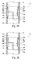
- FIGS 2A and 2B An alternative embodiment of the invention is shown in Figures 2A and 2B in which the syringe assembly 10 comprises an alternative stopper 14'. Apart from the alternative stopper 14', the syringe assembly 10 is otherwise identical to that described above in relation to Figures 1A and 1B .
- the alternative stopper 14' has a permanent seal 16 identical to that described above in relation to Figures 1A and 1B , and comprises a resilient seal 22.
- the resilient seal 22 depicted in Figures 2A and 2B is formed of a pair of flexible elements 22a',22b' each extending radially from the stopper 14' and arranged in axial alignment with one another.
- the resilient seal 22' of Figures 2A and 2B does not extend entirely circumferentially around the stopper 14' but is otherwise identical to resilient seal 22. Instead, the resilient seal 22' extends partly around the circumference of the stopper 14' and a second permanent seal 28 formed of a pair of flanges 28a,28b extending radially from the stopper 14' extend around the remainder of the circumference of the stopper 14' The second permanent seal 28 maintains a permanent seal between the stopper 14' and the barrel 12 across the extent of the circumference that it extends.
- the stopper 14' has a channel 18 that bypasses the permanent seal 16 and is formed of a first axial channel part 18a and a second channel part 18b arranged substantially perpendicularly to the first axial channel part 18a.
- a first opening 20a is associated with the first axial channel part 18a and a single second opening 20b is associated with the second channel part 18b.
- the channel 18 of Figures 2A and 2B is L-shaped in cross section, in contrast to the channel 18 of Figures 1A and 1B which is T-shaped in cross section.
- either channel arrangement may be used in either embodiment.
- other channel arrangements may be employed that bypass the permanent seal 16 from an outer radial position via an inner radial position that is radially inwards of the permanent seal 16.
- the stopper 14,14' is made from a deformable elastomeric material that is able to achieve a fluid tight seal with the barrel 12.
- the resilient seal 22' and the second permanent seal 28 are arranged relative to one another such that when the resilient seal 22' is in the sealing configuration (as shown in Figure 2A ) the combination of the resilient seal 22' and the second permanent seal 28 fluidly isolate the second opening 20b of the channel 18 from the first volume 24, and hence fluidly isolate the first volume 24 from the second volume 26.
- the resilient seal 22' permits a fluid pathway that fluidly connects the first volume 24 to an annulus circumferentially surrounding the stopper 14' between the axial positions of the permanent seal 16 and the second permanent seal 28.
- axial ribs or similar formations may be arranged on the stopper 14' on either side of the second opening in each circumferential direction so as to form an axial channel that forms a circumferential boundary around the second opening and seals with the barrel 12.
- the axial channel would be bound at a forward end by the permanent seal 16 and the axial channel would be bound at a rear end by resilient seal 22'. Since the second opening 20b is disposed within the bound axial channel, the second permanent seal 28 would not be necessary, however it is preferable that it still be present to minimise the risk of inadvertent fluid flow from the first volume 24 to the second volume 26.
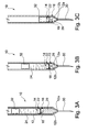
- Figures 3A to 3C A preferred mode of operation and arrangement of the syringe assembly 10 is shown in Figures 3A to 3C.
- Figure 3A shows the syringe assembly 10 prior to actuation containing a first fluid in the first volume 24 and a second fluid in the second volume 26.
- the first and second fluids may be medicaments and/or may be the same or different to one another.
- the first volume 24 is greater than the second volume 26, however this need not necessarily be the case.
- the barrel 12 has a tapered forward portion 12b that tapers to a narrowed opening or outlet 12a at the forwardmost end of the barrel 12, where the narrowed opening 12a has a diameter less than the diameter of the barrel 12.
- a hollow needle 30 is connected to the opening 12a of the barrel 12 to permit the expulsion of fluid from the barrel 12 through the opening 12a.
- the first volume 24 is defined as the volume between the plunger element 32 and the stopper 14 and the second volume is defined as the volume in the syringe assembly 10 forward of the stopper 14 and may include the volume inside the hollow needle 30.
- the stopper 14 is axially displaceable within the barrel 12 upon the application of an axial force on the stopper 14.
- the plunger element 32 is axially displaceable within the barrel 12 upon the application of an axial force on the plunger element 32.
- the needle 30 is inserted into an injection site and the plunger element is moved axially forwards within the barrel 12.
- the axially forward movement of the plunger element 32 may be achieved using a power source or by manually moving the plunger element 32.
- the plunger element 32 may additionally comprise a plunger rod connected to the plunger stopper to facilitate axial movement of the plunger stopper within the barrel 12.
- the plunger element 32 moves axially forwards within the barrel 12, it increases the fluid pressure of the first fluid in the first volume 24. Due to the incompressible nature of the first fluid, the force from the plunger element 32 is transferred axially to the stopper 14.
- any suitable mechanism that can apply a force to the first fluid may be used in alternative embodiments in place of the plunger element 32.
- the stopper 14 is configured such that the axial force required to axially move the stopper 14 within the barrel 12 is less than the force provided by a fluid at the pressure threshold that determines when the resilient seal 22 moves from the sealing configuration to the open configuration.
- initial forward force from the plunger element 32 on the first fluid causes the stopper 14 to move axially forwardly within the barrel 12.
- This action increases the pressure of the second fluid contained in the second volume 26 and causes the second fluid to be expelled from the syringe assembly 10 through the opening 12a and needle 30.
- the stopper 14 will continue to move axially forwards and expel the second fluid until the stopper 14 reaches the tapered forward portion 12b of the barrel 12.
- the axially forward force acting on the stopper 14 is met with an equal and opposite (i.e. axially rearward) reaction force from the tapered forward portion 12b of the barrel 12 and the stopper 14 ceases to move forwards.
- Subsequent force on the plunger element 32 causes the pressure of the first fluid in the first volume 24 to increase in pressure until the predetermined pressure threshold required to move the resilient seal 22 from the sealing configuration to the open configuration is exceeded. Once exceeded, the resilient seal 22 moves from the sealing configuration to the open configuration and the first fluid in the first volume 24 bypasses the permanent seal 18 into the second volume 26 and is expelled out of the syringe assembly through the opening 12a and the needle 30, as shown in Figure 3B .
- the device described in relation to Figures 3A to 3C may thus be used to deliver two sequential doses of medicament to an injection site, where the stopper 14 ensures the two volumes of fluid remain separate from one another prior to actuation.
- a syringe assembly 10 of this type may be useful for delivery of two medicaments that are unstable or less effective when mixed with one another.
- Further stoppers 14,14' may be included to permit the separation and subsequent sequential delivery of three or more substances.
- a first substance may be delivered using the syringe assembly 10 and the delivery process may then be interrupted so that the needle 30 (or alternative applicator) may be changed prior to the delivery of the second substance using the same syringe assembly 10.
- the needle 30 or other applicator may be changed prior to the delivery of each or any of the substances during the (interrupted) delivery procedure.
- the stopper 14 may be used to isolate a single volume of fluid from contact with certain components of the syringe assembly 10.
- the first volume 24 is defined between the stopper 14 and the plunger element 32 and contains a first fluid.
- the stopper 14 is disposed in the barrel 12 against the tapered forward portion 12b of the barrel 12 such that no further forward axial movement of the stopper 14 in the barrel 12 is possible.
- the second volume 26, axially forward of the stopper 14, does not contain any fluid or medicament.
- the first fluid is maintained in the first volume 24 and is isolated from the opening 12a of the barrel 12 and the needle 30.
- This arrangement may be advantageous in keeping sensitive medicaments isolated from the materials of the needle 30 and any adhesives used to affix the needle 30 to the opening 12a prior to actuation of the syringe assembly 10.
- Such contact between sensitive medicaments and the materials of the needle, any adhesives used to affix the needle in place, or any residual tungsten left from the manufacture of the syringe assembly (i.e. when forming the narrowed outlet 12a) may reduce or null the efficacy of the medicament over time.
- the arrangement shown in Figure 4A therefore allows sensitive medicaments to be stably stored in a syringe assembly 10 without the risk of its efficacy being reduced through material contamination.
- the medicament is only in contact with a limited number of materials, for example the stopper 14, the syringe barrel 12 and any silicon, if present (if, for example, the internal surface of the barrel 12 is siliconised).
- a limited number of materials for example the stopper 14, the syringe barrel 12 and any silicon, if present (if, for example, the internal surface of the barrel 12 is siliconised).
- the needle When the user is ready to deliver the first fluid in the first volume 24, the needle is inserted into the injection site and a force is applied to the plunger element 32 which in turn applies a force to the stopper 14 via the incompressible fluid in the first volume 24. If the stopper 14 is initially in the position shown in Figure 4A against the tapered forward portion 12b, then the stopper is unable to move axially forwards and the pressure of the first fluid increases. If, however, there is some "take-up", and the stopper 14 is initially axially rearward of the tapered forward portion 12b, then the stopper 14 moves axially forwardly under the influence of the force applied to the plunger element 32 until it reaches the tapered forward portion 12b, at which point the pressure of the first fluid begins to increase.
- the resilient seal 22 moves to the open configuration and the stopper permits the first fluid to leave the first volume 24 and enter the second volume 26 and be expelled from the syringe assemble 10 through the opening 12a and needle 30.
- the stopper 14 may be fixed axially within the barrel 12.
- examples of how the stopper 14 may be axially fixed within the barrel include but are not limited to radio frequency (RF) welding or heat welding.
- RF radio frequency
- the stopper 14 may be retained axially within the barrel 12 simply by friction between the stopper 14 and the barrel 12.
- the stopper 14 may be prevented from moving axially forwardly in the barrel 12 by abutment with the tapered forward portion 12b of the barrel 12.
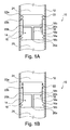
- FIGS 5A to 5D depict the various stages of operation of a syringe assembly 10.
- the syringe assembly 10 of Figures 5A to 5D is for mixing two substances prior to delivery.
- the two substances may include a dry or lyophilized medicament and a fluid diluent, or a dry or lyophilized medicament and a fluid medicament. It may be desirable for stability and/or efficacy reasons to keep the wet and dry substances separated prior to delivery (e.g. during storage of the syringe assembly 10).
- the syringe assembly 10 of Figure 5A is largely similar to that described above in relation to Figure 3A .
- the first volume 24 contains a fluid while the second volume 26 contains a dry or lyophilized substance.
- the stopper 14 initially separates the first and second volumes 24,26 just as described above with reference to Figure 3A .
- the stopper 14 of the syringe assembly 10 of Figure 5A is configured in the barrel 12 such that the force at the fluid pressure threshold that determines when the resilient seal 22 moves from the sealing configuration to the open configuration is less than the force required to move the stopper 14 axially in the barrel 12 (i.e. that required to overcome friction and other axial resistive forces).
- FIG. 5B shows the syringe assembly of Figure 5A during the "mixing" stage, where the resilient seal 22 is in its open configuration and the axially forwardly advancing plunger element 32 is pressurizing the fluid in the first volume and causing it to flow into the second volume via the channel 18, while the stopper 14 remains axially stationary within the barrel 12.
- the fluid from the first volume 24 therefore mixes with the dry or lyophilized substance in the second volume 26 to form a solution or mixture.
- the stopper 14 may additionally comprise a nozzle or spray head (not shown) at or near the first opening 20a to facilitate mixing of the fluid and dry or lyophilized substance in the second volume 26.
- FIG. 5D shows the syringe assembly 10 at the end of delivery where the plunger element 32 and stopper 14 have moved to their forwardmost axial position in the barrel 12, with the stopper 14 abutting the tapered forward portion 12b of the barrel 12. At this point, the syringe assembly 10 may be removed from the injection site.
- the stopper 14" includes a friction clamp 34 that increases the frictional forces required to move the stopper 14" axially forwardly within the barrel 12.
- the stopper 14" may be a two-shot moulding where the first shot forms the friction clamp 34 from a plastics material or the like and the second shot forms the remainder of the stopper 14" from an elastomer material or the like.
- the stopper 14" additionally has a socket 36 formed therein that is capable of receiving a complementary key 32a that is formed on the front side of the plunger element 32. When the key 32a is received in the socket 36, the clamping load (i.e. the frictional and resistive forces) provided by the friction clamp 34 is reduced, thereby lowering the threshold force required to move the stopper 14" axially forwardly in the barrel 12.
- Figure 6A The arrangement shown in Figure 6A is equivalent to that shown in Figure 5A where a fluid substance is contained in the first volume 24 and a dry or lyophilized substance is contained in the second volume 26, prior to actuation.
- Figure 6B shows an equivalent arrangement to that shown in Figure 5B , where the axially forwardly force on the plunger element 32 has caused the plunger element 32 to move axially forwardly in the barrel 12 towards the stationary stopper 14" causing the resilient seal to move into the open configuration and forcing the fluid from the first volume 24 to flow into the second volume 26 through the channel 18.
- the plunger element 32 has moved axially forwardly in the barrel 12 and has met the stopper 14" such that the key 32a of the plunger element 32 is inserted into the socket 36 of the stopper 14".
- the mating of the key 32a and socket 36 components causes the clamping load of the stopper 14" to be reduced. Therefore, further axially forward movement of the plunger element 32 causes axially forward movement of the stopper 14", thus expelling the solution or mixture formed in the second volume 26 from the syringe assembly 10 via the opening 12a and needle 30.
- Figure 6D shows the syringe assembly 10 at the end of delivery where the plunger element 32 and stopper 14" have moved to their forwardmost axial position in the barrel 12, with the stopper 14" abutting the tapered forward portion 12b of the barrel 12. At this point, the syringe assembly 10 may be removed from the injection site.
- the arrangement of Figures 6A to 6D has the additional advantage over the arrangement of Figures 5A to 5D in that the force required to move the stopper 14" is higher due to the presence of the friction clamp 34.
- the key 32a and socket 36 arrangement of the embodiment of Figures 6A to 6D means that the force required to actually move the stopper 14" axially forwardly when desired is achievable within the reasonable operating limits of the syringe assembly 10. Therefore, the friction clamp 34 provides less risk of unwanted axial movement of the stopper 14" prior to the completion of mixing between the first volume 24 and the second volume 26.
- the syringe assembly 10 of the present invention may be used as a manual device or as part of an autoinjector device.
- the syringe assembly 10 may be configured such that the needle 30 is automatically inserted and removed from the injection site, prior to and after delivery, respectively.
- stoppers 14,14' and any described alternatives or modifications of the stoppers 14,14' may be utilized in a syringe assembly 10 in accordance with the present invention.
- the stopper 14" described in relation to Figures 6A to 6D may be used in "mixing"-type devices within the scope of the present invention. All stoppers in accordance with the present invention are particularly advantageous as each provides an effective and reliable two-way valve for separating two substances or isolating a single substance.
- the stopper may be used in existing syringes thereby negating the requirement for bespoke syringes.
- the stopper of the present invention may be easily and cost-effectively moulded in comparison to prior art components that seek to provide a similar effect.
- the syringe assembly 10 of the present invention is easy to manufacture in comparison to more complicated prior art arrangements.
- a further advantage of the syringe assembly 10 of the present invention is that it may be filled with relative ease in comparison with prior art devices.
- Each substance is introduced into the barrel sequentially from the rear (i.e. the end opposite the narrowed opening or outlet) with the stopper (or stoppers) being inserted in the sequence where desired. Therefore, standard syringe filling apparatus that is common in the art may be used to fill the syringe assembly, and no specially adapted filling apparatus need necessarily be used.
- Two or more stoppers 14,14' may be employed in a single syringe assembly 10 to provide selective sealing between several volumes in the syringe assembly 10.
- three medicaments may be delivered sequentially by utilizing two stoppers 14,14' intermediate the opening 12a and the plunger element 32 or equivalent means for providing a forward force.
- the syringe assembly 10 may consist of a combination of the embodiments shown in Figures 3A to 3C and Figures 4A to 4B in that a front stopper 14,14' may be used to isolate the contents of the syringe assembly 10 from the opening 12a and needle 30 whilst further stoppers 14,14' may be utilized to permit a multi-dose, sequential delivery.
- the syringe assembly 10 may be a combination of any of the described embodiments so that the syringe assembly 10 is capable of any one or more of: sequential delivery, mixing of two or more substances, and medicament isolation. Indeed, the syringe assembly 10 may be arranged to be capable of all three of these modes of operation, such that medicaments are initially isolated from one another and the narrowed outlet (and any needle present). Upon actuation of the syringe assembly 10, two or more of the substances may be mixed in accordance with the mechanism described above in relation to Figures 5A to 5D or Figures 6A to 6D and then delivered, before being delivered, following the sequential delivery of one or more substances stored axially rearward of the two or more substances that are mixed.
- the syringe assembly 10 may include a separate component that serves as a narrowed opening 12a for allowing the expulsion of fluid from the syringe assembly 10.
- the syringe assembly 10 of the present invention may be used with a needle 30 or other applicator in fluid communication with the opening 12a.
Landscapes
- Health & Medical Sciences (AREA)
- Vascular Medicine (AREA)
- Engineering & Computer Science (AREA)
- Anesthesiology (AREA)
- Biomedical Technology (AREA)
- Heart & Thoracic Surgery (AREA)
- Hematology (AREA)
- Life Sciences & Earth Sciences (AREA)
- Animal Behavior & Ethology (AREA)
- General Health & Medical Sciences (AREA)
- Public Health (AREA)
- Veterinary Medicine (AREA)
- Infusion, Injection, And Reservoir Apparatuses (AREA)
Priority Applications (2)
| Application Number | Priority Date | Filing Date | Title |
|---|---|---|---|
| SI201330478A SI2817043T1 (sl) | 2012-02-22 | 2013-02-22 | Izboljšan sklop brizge |
| PL13708230T PL2817043T3 (pl) | 2012-02-22 | 2013-02-22 | Usprawniony zespół strzykawki |
Applications Claiming Priority (2)
| Application Number | Priority Date | Filing Date | Title |
|---|---|---|---|
| GB1203015.1A GB2499612A (en) | 2012-02-22 | 2012-02-22 | Syringe assembly with a stopper |
| PCT/GB2013/050438 WO2013124669A1 (en) | 2012-02-22 | 2013-02-22 | Improved syringe assembly |
Publications (2)
| Publication Number | Publication Date |
|---|---|
| EP2817043A1 EP2817043A1 (en) | 2014-12-31 |
| EP2817043B1 true EP2817043B1 (en) | 2016-10-26 |
Family
ID=45939986
Family Applications (1)
| Application Number | Title | Priority Date | Filing Date |
|---|---|---|---|
| EP13708230.1A Active EP2817043B1 (en) | 2012-02-22 | 2013-02-22 | Improved syringe assembly |
Country Status (17)
| Country | Link |
|---|---|
| US (1) | US9962492B2 (enExample) |
| EP (1) | EP2817043B1 (enExample) |
| JP (1) | JP6381447B2 (enExample) |
| CN (1) | CN104144720B (enExample) |
| AU (1) | AU2013223804B2 (enExample) |
| CA (1) | CA2864405C (enExample) |
| CY (1) | CY1118558T1 (enExample) |
| DK (1) | DK2817043T3 (enExample) |
| ES (1) | ES2608462T3 (enExample) |
| GB (1) | GB2499612A (enExample) |
| HU (1) | HUE032473T2 (enExample) |
| IN (1) | IN2014DN07272A (enExample) |
| LT (1) | LT2817043T (enExample) |
| PL (1) | PL2817043T3 (enExample) |
| PT (1) | PT2817043T (enExample) |
| SI (1) | SI2817043T1 (enExample) |
| WO (1) | WO2013124669A1 (enExample) |
Cited By (1)
| Publication number | Priority date | Publication date | Assignee | Title |
|---|---|---|---|---|
| DE102017125703A1 (de) | 2016-11-04 | 2018-05-09 | Datwyler Pharma Packaging International Nv | Im Kunststoff-Spritzverfahren hergestellter Kolben für eine medizinische Spritze und eine medizinische Spritze |
Families Citing this family (28)
| Publication number | Priority date | Publication date | Assignee | Title |
|---|---|---|---|---|
| US9199037B2 (en) | 2013-03-15 | 2015-12-01 | Windgap Medical, Inc. | Portable drug mixing and delivery system and method |
| US12239822B2 (en) | 2013-03-15 | 2025-03-04 | Windgap Medical, Inc. | Portable drug mixing and delivery device and associated methods |
| US9907910B2 (en) | 2013-03-15 | 2018-03-06 | Windgap Medical, Inc. | Portable drug mixing and delivery device and associated methods |
| US10569017B2 (en) | 2013-03-15 | 2020-02-25 | Windgap Medical, Inc. | Portable drug mixing and delivery device and associated methods |
| US20140276379A1 (en) | 2013-03-15 | 2014-09-18 | Medrad, Inc. | Intelligent and configurable fluid delivery system and methods for its use |
| GB201305489D0 (en) * | 2013-03-26 | 2013-05-08 | Consort Medical Plc | Improved syringe assembly |
| EP3082419A4 (en) | 2013-12-18 | 2017-09-20 | Windgap Medical, Inc. | Drug mixing and delivery system and method |
| US11116903B2 (en) | 2014-08-18 | 2021-09-14 | Windgap Medical, Inc | Compression seal for use with a liquid component storage vial of an auto-injector |
| CN106573111B (zh) | 2014-08-18 | 2020-03-31 | 温德加普医疗股份有限公司 | 便携式药物混合和递送装置及相关方法 |
| CN107205938A (zh) | 2014-12-18 | 2017-09-26 | 温德加普医疗股份有限公司 | 用于溶解或增溶治疗剂的方法和组合物 |
| KR102450955B1 (ko) * | 2014-12-30 | 2022-10-04 | 쓰리엠 이노베이티브 프로퍼티즈 컴파니 | 유체 약제 성분들을 혼합 및 분배하기 위한 용기 |
| WO2016109336A1 (en) | 2014-12-30 | 2016-07-07 | 3M Innovative Properties Company | Container for mixing and dispensing two components |
| WO2016109342A1 (en) * | 2014-12-30 | 2016-07-07 | 3M Innovative Properties Company | Container for mixing and dispensing components |
| JP6580777B2 (ja) | 2015-08-13 | 2019-09-25 | ウィンドギャップ メディカル, インコーポレイテッド | 無菌特徴を有する混合及び注入装置 |
| EP3525872B1 (en) * | 2016-10-17 | 2020-09-02 | Bayer Healthcare LLC | Fluid control valve and manifold |
| EP3562529A4 (en) | 2016-12-27 | 2021-03-03 | Action Medical Technologies, LLC | APPARATUS AND METHOD FOR INJECTING MEDICINES |
| US10493207B2 (en) * | 2017-02-27 | 2019-12-03 | W. L. Gore & Associates, Inc. | Medical delivery devices having low lubricant syringe barrels |
| US11224696B2 (en) | 2018-07-10 | 2022-01-18 | Action Medical Technologies, Llc | Apparatuses and method for injecting medicaments |
| EP4424345A3 (en) | 2020-03-17 | 2024-11-06 | Becton Dickinson France | Stopper for a medical injection device |
| EP4126128B1 (en) | 2020-03-25 | 2025-11-19 | Action Medical Technologies, LLC | Apparatuses and methods for injecting medicaments |
| US11759576B2 (en) | 2020-06-05 | 2023-09-19 | Action Medical Technologies, Llc | Parenteral injection apparatus |
| DK4135830T3 (da) | 2020-12-23 | 2024-10-28 | Tolmar International Ltd | Systemer og fremgangsmåder til blanding af sprøjteventilanordninger |
| AU2022293196A1 (en) | 2021-06-15 | 2023-12-14 | Sadleir Laboratories Pty Ltd | Medication delivery systems, apparatuses and methods |
| EP4504300A4 (en) * | 2022-04-04 | 2026-02-25 | Becton Dickinson Co | MULTI-CHARBORNE SYRINGE FOR SEQUENTIAL DISTRIBUTION OF FLUIDS AND METHODS OF USE |
| US20250229036A1 (en) * | 2022-04-04 | 2025-07-17 | Becton, Dickinson And Company | Multi-Chamber Syringe with Pressure Valve for Sequential Delivery of Fluids and Methods of Use |
| USD1029245S1 (en) | 2022-06-22 | 2024-05-28 | Tolmar International Limited | Syringe connector |
| US20240226436A9 (en) * | 2022-10-25 | 2024-07-11 | Becton, Dickinson And Company | Barrier Coated Sequential Stopper for a Multi-Chamber Syringe |
| GB2629028A (en) * | 2023-04-14 | 2024-10-16 | Salinity Solutions Ltd | Membrane filtration system |
Family Cites Families (19)
| Publication number | Priority date | Publication date | Assignee | Title |
|---|---|---|---|---|
| US3076456A (en) * | 1960-03-07 | 1963-02-05 | Elsie B Hunt | Hypodermic syringe |
| US3699961A (en) * | 1970-03-12 | 1972-10-24 | Sebon Corp The | Syringe and method |
| US3914419A (en) * | 1973-08-02 | 1975-10-21 | American Cyanamid Co | Two compartment one unit consecutively injectable liquid vitamin package |
| EP0112574A1 (fr) * | 1982-12-27 | 1984-07-04 | Meditec S.A. | Seringue préremplie à double compartiment |
| CH666870A5 (fr) * | 1986-04-10 | 1988-08-31 | Cosmonor Sa | Dispositif de conditionnement de substances liquides ou liquides et solides. |
| US4929230A (en) * | 1988-09-30 | 1990-05-29 | Pfleger Frederick W | Syringe construction |
| US5078691A (en) * | 1990-03-01 | 1992-01-07 | Hamacher Edward N | Multiple-dose fluid delivery system and method |
| GB9223183D0 (en) | 1992-11-05 | 1992-12-16 | Medimech Int Ltd | Improvements related to auto injectors |
| AP916A (en) * | 1996-05-03 | 2000-12-18 | Nordway Ltd | Vial for use as a syringe accessory. |
| FR2750051A1 (fr) | 1996-06-21 | 1997-12-26 | Debiotech Sa | Seringue medicale a piston libre |
| US5713857A (en) * | 1996-06-28 | 1998-02-03 | Becton Dickinson France, S.A. | Sequential stopper |
| FR2793708B1 (fr) * | 1999-05-21 | 2001-08-03 | Valois Sa | Dispositif de distribution de produit fluide |
| US6953445B2 (en) | 2000-10-10 | 2005-10-11 | Meridian Medical Technologies, Inc. | Wet/dry automatic injector assembly |
| AR026723A1 (es) * | 2000-12-05 | 2003-02-26 | Szames Leonardo | Conjunto valvular elastico y deslizante apto para actuar en el interior de jeringas prellenadas. |
| US6387078B1 (en) * | 2000-12-21 | 2002-05-14 | Gillespie, Iii Richard D. | Automatic mixing and injecting apparatus |
| US7077827B2 (en) | 2002-08-30 | 2006-07-18 | Christian John Greenfield | Syringe for sequential delivery of different fluids |
| US6997910B2 (en) | 2004-05-03 | 2006-02-14 | Infusive Technologies, Llc | Multi-chamber, sequential dose dispensing syringe |
| JP2008259704A (ja) * | 2007-04-12 | 2008-10-30 | Hisamitsu Pharmaceut Co Inc | プレフィルド型シリンジ |
| WO2009091683A1 (en) * | 2008-01-17 | 2009-07-23 | Becton, Dickinson And Company | Valve for mixing of substances |
-
2012
- 2012-02-22 GB GB1203015.1A patent/GB2499612A/en not_active Withdrawn
-
2013
- 2013-02-22 ES ES13708230.1T patent/ES2608462T3/es active Active
- 2013-02-22 WO PCT/GB2013/050438 patent/WO2013124669A1/en not_active Ceased
- 2013-02-22 IN IN7272DEN2014 patent/IN2014DN07272A/en unknown
- 2013-02-22 LT LTEP13708230.1T patent/LT2817043T/lt unknown
- 2013-02-22 AU AU2013223804A patent/AU2013223804B2/en active Active
- 2013-02-22 PT PT137082301T patent/PT2817043T/pt unknown
- 2013-02-22 HU HUE13708230A patent/HUE032473T2/en unknown
- 2013-02-22 CA CA2864405A patent/CA2864405C/en active Active
- 2013-02-22 JP JP2014558208A patent/JP6381447B2/ja active Active
- 2013-02-22 EP EP13708230.1A patent/EP2817043B1/en active Active
- 2013-02-22 CN CN201380010440.9A patent/CN104144720B/zh active Active
- 2013-02-22 PL PL13708230T patent/PL2817043T3/pl unknown
- 2013-02-22 SI SI201330478A patent/SI2817043T1/sl unknown
- 2013-02-22 DK DK13708230.1T patent/DK2817043T3/en active
- 2013-02-22 US US14/380,334 patent/US9962492B2/en active Active
-
2017
- 2017-01-05 CY CY20171100016T patent/CY1118558T1/el unknown
Cited By (2)
| Publication number | Priority date | Publication date | Assignee | Title |
|---|---|---|---|---|
| DE102017125703A1 (de) | 2016-11-04 | 2018-05-09 | Datwyler Pharma Packaging International Nv | Im Kunststoff-Spritzverfahren hergestellter Kolben für eine medizinische Spritze und eine medizinische Spritze |
| WO2018083221A1 (de) | 2016-11-04 | 2018-05-11 | Datwyler Pharma Packaging International Nv | Im kunststoff-spritzverfahren hergestellter kolben für eine medizinische spritze und eine medizinische spritze |
Also Published As
| Publication number | Publication date |
|---|---|
| PL2817043T3 (pl) | 2017-06-30 |
| EP2817043A1 (en) | 2014-12-31 |
| GB2499612A (en) | 2013-08-28 |
| DK2817043T3 (en) | 2017-01-30 |
| LT2817043T (lt) | 2017-02-10 |
| CY1118558T1 (el) | 2017-07-12 |
| CA2864405A1 (en) | 2013-08-29 |
| CN104144720B (zh) | 2016-11-09 |
| CN104144720A (zh) | 2014-11-12 |
| AU2013223804A1 (en) | 2014-09-11 |
| JP2015507997A (ja) | 2015-03-16 |
| US20150011975A1 (en) | 2015-01-08 |
| ES2608462T3 (es) | 2017-04-11 |
| GB201203015D0 (en) | 2012-04-04 |
| HUE032473T2 (en) | 2017-10-30 |
| US9962492B2 (en) | 2018-05-08 |
| CA2864405C (en) | 2020-06-02 |
| IN2014DN07272A (enExample) | 2015-04-24 |
| WO2013124669A1 (en) | 2013-08-29 |
| AU2013223804B2 (en) | 2017-07-13 |
| SI2817043T1 (sl) | 2017-03-31 |
| JP6381447B2 (ja) | 2018-08-29 |
| PT2817043T (pt) | 2017-01-19 |
Similar Documents
| Publication | Publication Date | Title |
|---|---|---|
| EP2817043B1 (en) | Improved syringe assembly | |
| US10080882B2 (en) | Valved container assembly | |
| CN107469198B (zh) | 改进的混合注射器组件 | |
| US10646639B2 (en) | Valved container assembly | |
| AU2021237695B2 (en) | Stopper for a medical injection device | |
| EP3576816B1 (en) | A medicament delivery device | |
| HK1242239A1 (en) | Improved mixing syringe assembly |
Legal Events
| Date | Code | Title | Description |
|---|---|---|---|
| PUAI | Public reference made under article 153(3) epc to a published international application that has entered the european phase |
Free format text: ORIGINAL CODE: 0009012 |
|
| 17P | Request for examination filed |
Effective date: 20140912 |
|
| AK | Designated contracting states |
Kind code of ref document: A1 Designated state(s): AL AT BE BG CH CY CZ DE DK EE ES FI FR GB GR HR HU IE IS IT LI LT LU LV MC MK MT NL NO PL PT RO RS SE SI SK SM TR |
|
| AX | Request for extension of the european patent |
Extension state: BA ME |
|
| DAX | Request for extension of the european patent (deleted) | ||
| GRAP | Despatch of communication of intention to grant a patent |
Free format text: ORIGINAL CODE: EPIDOSNIGR1 |
|
| RIC1 | Information provided on ipc code assigned before grant |
Ipc: A61M 5/315 20060101ALI20160616BHEP Ipc: A61M 5/28 20060101AFI20160616BHEP Ipc: A61M 5/178 20060101ALN20160616BHEP |
|
| RIC1 | Information provided on ipc code assigned before grant |
Ipc: A61M 5/178 20060101ALN20160621BHEP Ipc: A61M 5/28 20060101AFI20160621BHEP Ipc: A61M 5/315 20060101ALI20160621BHEP |
|
| INTG | Intention to grant announced |
Effective date: 20160720 |
|
| GRAS | Grant fee paid |
Free format text: ORIGINAL CODE: EPIDOSNIGR3 |
|
| GRAA | (expected) grant |
Free format text: ORIGINAL CODE: 0009210 |
|
| RIN1 | Information on inventor provided before grant (corrected) |
Inventor name: ANDERSON, IAN Inventor name: EKMAN, MATT |
|
| AK | Designated contracting states |
Kind code of ref document: B1 Designated state(s): AL AT BE BG CH CY CZ DE DK EE ES FI FR GB GR HR HU IE IS IT LI LT LU LV MC MK MT NL NO PL PT RO RS SE SI SK SM TR |
|
| REG | Reference to a national code |
Ref country code: GB Ref legal event code: FG4D |
|
| REG | Reference to a national code |
Ref country code: CH Ref legal event code: EP |
|
| REG | Reference to a national code |
Ref country code: AT Ref legal event code: REF Ref document number: 839572 Country of ref document: AT Kind code of ref document: T Effective date: 20161115 |
|
| REG | Reference to a national code |
Ref country code: IE Ref legal event code: FG4D |
|
| REG | Reference to a national code |
Ref country code: DE Ref legal event code: R096 Ref document number: 602013013189 Country of ref document: DE |
|
| REG | Reference to a national code |
Ref country code: RO Ref legal event code: EPE |
|
| REG | Reference to a national code |
Ref country code: NL Ref legal event code: FP |
|
| REG | Reference to a national code |
Ref country code: PT Ref legal event code: SC4A Ref document number: 2817043 Country of ref document: PT Date of ref document: 20170119 Kind code of ref document: T Free format text: AVAILABILITY OF NATIONAL TRANSLATION Effective date: 20170110 |
|
| REG | Reference to a national code |
Ref country code: DK Ref legal event code: T3 Effective date: 20170126 |
|
| REG | Reference to a national code |
Ref country code: CH Ref legal event code: NV Representative=s name: MICHELI AND CIE SA, CH |
|
| REG | Reference to a national code |
Ref country code: SE Ref legal event code: TRGR |
|
| REG | Reference to a national code |
Ref country code: FR Ref legal event code: PLFP Year of fee payment: 5 |
|
| REG | Reference to a national code |
Ref country code: EE Ref legal event code: FG4A Ref document number: E013153 Country of ref document: EE Effective date: 20170112 |
|
| REG | Reference to a national code |
Ref country code: ES Ref legal event code: FG2A Ref document number: 2608462 Country of ref document: ES Kind code of ref document: T3 Effective date: 20170411 |
|
| PG25 | Lapsed in a contracting state [announced via postgrant information from national office to epo] |
Ref country code: NO Free format text: LAPSE BECAUSE OF FAILURE TO SUBMIT A TRANSLATION OF THE DESCRIPTION OR TO PAY THE FEE WITHIN THE PRESCRIBED TIME-LIMIT Effective date: 20170126 |
|
| PG25 | Lapsed in a contracting state [announced via postgrant information from national office to epo] |
Ref country code: IS Free format text: LAPSE BECAUSE OF FAILURE TO SUBMIT A TRANSLATION OF THE DESCRIPTION OR TO PAY THE FEE WITHIN THE PRESCRIBED TIME-LIMIT Effective date: 20170226 Ref country code: HR Free format text: LAPSE BECAUSE OF FAILURE TO SUBMIT A TRANSLATION OF THE DESCRIPTION OR TO PAY THE FEE WITHIN THE PRESCRIBED TIME-LIMIT Effective date: 20161026 Ref country code: RS Free format text: LAPSE BECAUSE OF FAILURE TO SUBMIT A TRANSLATION OF THE DESCRIPTION OR TO PAY THE FEE WITHIN THE PRESCRIBED TIME-LIMIT Effective date: 20161026 |
|
| REG | Reference to a national code |
Ref country code: DE Ref legal event code: R097 Ref document number: 602013013189 Country of ref document: DE |
|
| PG25 | Lapsed in a contracting state [announced via postgrant information from national office to epo] |
Ref country code: SM Free format text: LAPSE BECAUSE OF FAILURE TO SUBMIT A TRANSLATION OF THE DESCRIPTION OR TO PAY THE FEE WITHIN THE PRESCRIBED TIME-LIMIT Effective date: 20161026 |
|
| PLBE | No opposition filed within time limit |
Free format text: ORIGINAL CODE: 0009261 |
|
| STAA | Information on the status of an ep patent application or granted ep patent |
Free format text: STATUS: NO OPPOSITION FILED WITHIN TIME LIMIT |
|
| PG25 | Lapsed in a contracting state [announced via postgrant information from national office to epo] |
Ref country code: MC Free format text: LAPSE BECAUSE OF FAILURE TO SUBMIT A TRANSLATION OF THE DESCRIPTION OR TO PAY THE FEE WITHIN THE PRESCRIBED TIME-LIMIT Effective date: 20161026 |
|
| 26N | No opposition filed |
Effective date: 20170727 |
|
| REG | Reference to a national code |
Ref country code: HU Ref legal event code: AG4A Ref document number: E032473 Country of ref document: HU |
|
| REG | Reference to a national code |
Ref country code: SK Ref legal event code: T3 Ref document number: E 24397 Country of ref document: SK |
|
| REG | Reference to a national code |
Ref country code: FR Ref legal event code: PLFP Year of fee payment: 6 |
|
| PG25 | Lapsed in a contracting state [announced via postgrant information from national office to epo] |
Ref country code: MT Free format text: LAPSE BECAUSE OF NON-PAYMENT OF DUE FEES Effective date: 20170222 |
|
| REG | Reference to a national code |
Ref country code: AT Ref legal event code: UEP Ref document number: 839572 Country of ref document: AT Kind code of ref document: T Effective date: 20161026 |
|
| PG25 | Lapsed in a contracting state [announced via postgrant information from national office to epo] |
Ref country code: MK Free format text: LAPSE BECAUSE OF FAILURE TO SUBMIT A TRANSLATION OF THE DESCRIPTION OR TO PAY THE FEE WITHIN THE PRESCRIBED TIME-LIMIT Effective date: 20161026 |
|
| PG25 | Lapsed in a contracting state [announced via postgrant information from national office to epo] |
Ref country code: AL Free format text: LAPSE BECAUSE OF FAILURE TO SUBMIT A TRANSLATION OF THE DESCRIPTION OR TO PAY THE FEE WITHIN THE PRESCRIBED TIME-LIMIT Effective date: 20161026 |
|
| P01 | Opt-out of the competence of the unified patent court (upc) registered |
Effective date: 20230317 |
|
| PGFP | Annual fee paid to national office [announced via postgrant information from national office to epo] |
Ref country code: BG Payment date: 20250114 Year of fee payment: 13 |
|
| PGFP | Annual fee paid to national office [announced via postgrant information from national office to epo] |
Ref country code: SI Payment date: 20250127 Year of fee payment: 13 |
|
| PGFP | Annual fee paid to national office [announced via postgrant information from national office to epo] |
Ref country code: ES Payment date: 20250512 Year of fee payment: 13 |
|
| PGFP | Annual fee paid to national office [announced via postgrant information from national office to epo] |
Ref country code: DK Payment date: 20251223 Year of fee payment: 14 |
|
| REG | Reference to a national code |
Ref country code: CH Ref legal event code: U11 Free format text: ST27 STATUS EVENT CODE: U-0-0-U10-U11 (AS PROVIDED BY THE NATIONAL OFFICE) Effective date: 20260301 |
|
| PGFP | Annual fee paid to national office [announced via postgrant information from national office to epo] |
Ref country code: LU Payment date: 20260204 Year of fee payment: 14 Ref country code: NL Payment date: 20260205 Year of fee payment: 14 |
|
| PGFP | Annual fee paid to national office [announced via postgrant information from national office to epo] |
Ref country code: HU Payment date: 20260127 Year of fee payment: 14 |
|
| PGFP | Annual fee paid to national office [announced via postgrant information from national office to epo] |
Ref country code: SE Payment date: 20260129 Year of fee payment: 14 |
|
| PGFP | Annual fee paid to national office [announced via postgrant information from national office to epo] |
Ref country code: GB Payment date: 20260213 Year of fee payment: 14 Ref country code: LT Payment date: 20260123 Year of fee payment: 14 |
|
| PGFP | Annual fee paid to national office [announced via postgrant information from national office to epo] |
Ref country code: IE Payment date: 20260206 Year of fee payment: 14 Ref country code: DE Payment date: 20260206 Year of fee payment: 14 |
|
| PGFP | Annual fee paid to national office [announced via postgrant information from national office to epo] |
Ref country code: AT Payment date: 20260206 Year of fee payment: 14 |
|
| PGFP | Annual fee paid to national office [announced via postgrant information from national office to epo] |
Ref country code: RO Payment date: 20260126 Year of fee payment: 14 Ref country code: BE Payment date: 20260204 Year of fee payment: 14 Ref country code: FI Payment date: 20260209 Year of fee payment: 14 Ref country code: IT Payment date: 20260130 Year of fee payment: 14 |
|
| PGFP | Annual fee paid to national office [announced via postgrant information from national office to epo] |
Ref country code: FR Payment date: 20260213 Year of fee payment: 14 |
|
| PGFP | Annual fee paid to national office [announced via postgrant information from national office to epo] |
Ref country code: TR Payment date: 20260129 Year of fee payment: 14 |
|
| PGFP | Annual fee paid to national office [announced via postgrant information from national office to epo] |
Ref country code: PT Payment date: 20260205 Year of fee payment: 14 Ref country code: CZ Payment date: 20260123 Year of fee payment: 14 Ref country code: CH Payment date: 20260301 Year of fee payment: 14 |
|
| PGFP | Annual fee paid to national office [announced via postgrant information from national office to epo] |
Ref country code: GR Payment date: 20260206 Year of fee payment: 14 Ref country code: PL Payment date: 20260128 Year of fee payment: 14 Ref country code: CY Payment date: 20260126 Year of fee payment: 14 |
|
| PGFP | Annual fee paid to national office [announced via postgrant information from national office to epo] |
Ref country code: EE Payment date: 20260209 Year of fee payment: 14 Ref country code: LV Payment date: 20260206 Year of fee payment: 14 Ref country code: SK Payment date: 20260123 Year of fee payment: 14 |