EP2816631B1 - Batterieverstärkungsverfahren - Google Patents
Batterieverstärkungsverfahren Download PDFInfo
- Publication number
- EP2816631B1 EP2816631B1 EP13748485.3A EP13748485A EP2816631B1 EP 2816631 B1 EP2816631 B1 EP 2816631B1 EP 13748485 A EP13748485 A EP 13748485A EP 2816631 B1 EP2816631 B1 EP 2816631B1
- Authority
- EP
- European Patent Office
- Prior art keywords
- edge
- battery
- external packaging
- reinforcing part
- battery cell
- Prior art date
- Legal status (The legal status is an assumption and is not a legal conclusion. Google has not performed a legal analysis and makes no representation as to the accuracy of the status listed.)
- Active
Links
Images


Classifications
-
- H—ELECTRICITY
- H01—ELECTRIC ELEMENTS
- H01M—PROCESSES OR MEANS, e.g. BATTERIES, FOR THE DIRECT CONVERSION OF CHEMICAL ENERGY INTO ELECTRICAL ENERGY
- H01M50/00—Constructional details or processes of manufacture of the non-active parts of electrochemical cells other than fuel cells, e.g. hybrid cells
- H01M50/10—Primary casings; Jackets or wrappings
- H01M50/116—Primary casings; Jackets or wrappings characterised by the material
- H01M50/121—Organic material
-
- H—ELECTRICITY
- H01—ELECTRIC ELEMENTS
- H01M—PROCESSES OR MEANS, e.g. BATTERIES, FOR THE DIRECT CONVERSION OF CHEMICAL ENERGY INTO ELECTRICAL ENERGY
- H01M50/00—Constructional details or processes of manufacture of the non-active parts of electrochemical cells other than fuel cells, e.g. hybrid cells
- H01M50/10—Primary casings; Jackets or wrappings
- H01M50/102—Primary casings; Jackets or wrappings characterised by their shape or physical structure
- H01M50/105—Pouches or flexible bags
-
- H—ELECTRICITY
- H01—ELECTRIC ELEMENTS
- H01M—PROCESSES OR MEANS, e.g. BATTERIES, FOR THE DIRECT CONVERSION OF CHEMICAL ENERGY INTO ELECTRICAL ENERGY
- H01M50/00—Constructional details or processes of manufacture of the non-active parts of electrochemical cells other than fuel cells, e.g. hybrid cells
- H01M50/10—Primary casings; Jackets or wrappings
- H01M50/116—Primary casings; Jackets or wrappings characterised by the material
- H01M50/117—Inorganic material
- H01M50/119—Metals
-
- H—ELECTRICITY
- H01—ELECTRIC ELEMENTS
- H01M—PROCESSES OR MEANS, e.g. BATTERIES, FOR THE DIRECT CONVERSION OF CHEMICAL ENERGY INTO ELECTRICAL ENERGY
- H01M50/00—Constructional details or processes of manufacture of the non-active parts of electrochemical cells other than fuel cells, e.g. hybrid cells
- H01M50/10—Primary casings; Jackets or wrappings
- H01M50/116—Primary casings; Jackets or wrappings characterised by the material
- H01M50/124—Primary casings; Jackets or wrappings characterised by the material having a layered structure
-
- H—ELECTRICITY
- H01—ELECTRIC ELEMENTS
- H01M—PROCESSES OR MEANS, e.g. BATTERIES, FOR THE DIRECT CONVERSION OF CHEMICAL ENERGY INTO ELECTRICAL ENERGY
- H01M50/00—Constructional details or processes of manufacture of the non-active parts of electrochemical cells other than fuel cells, e.g. hybrid cells
- H01M50/10—Primary casings; Jackets or wrappings
- H01M50/14—Primary casings; Jackets or wrappings for protecting against damage caused by external factors
-
- H—ELECTRICITY
- H01—ELECTRIC ELEMENTS
- H01M—PROCESSES OR MEANS, e.g. BATTERIES, FOR THE DIRECT CONVERSION OF CHEMICAL ENERGY INTO ELECTRICAL ENERGY
- H01M50/00—Constructional details or processes of manufacture of the non-active parts of electrochemical cells other than fuel cells, e.g. hybrid cells
- H01M50/50—Current conducting connections for cells or batteries
- H01M50/543—Terminals
- H01M50/547—Terminals characterised by the disposition of the terminals on the cells
- H01M50/55—Terminals characterised by the disposition of the terminals on the cells on the same side of the cell
-
- H—ELECTRICITY
- H01—ELECTRIC ELEMENTS
- H01M—PROCESSES OR MEANS, e.g. BATTERIES, FOR THE DIRECT CONVERSION OF CHEMICAL ENERGY INTO ELECTRICAL ENERGY
- H01M50/00—Constructional details or processes of manufacture of the non-active parts of electrochemical cells other than fuel cells, e.g. hybrid cells
- H01M50/50—Current conducting connections for cells or batteries
- H01M50/543—Terminals
- H01M50/552—Terminals characterised by their shape
- H01M50/553—Terminals adapted for prismatic, pouch or rectangular cells
- H01M50/557—Plate-shaped terminals
-
- Y—GENERAL TAGGING OF NEW TECHNOLOGICAL DEVELOPMENTS; GENERAL TAGGING OF CROSS-SECTIONAL TECHNOLOGIES SPANNING OVER SEVERAL SECTIONS OF THE IPC; TECHNICAL SUBJECTS COVERED BY FORMER USPC CROSS-REFERENCE ART COLLECTIONS [XRACs] AND DIGESTS
- Y02—TECHNOLOGIES OR APPLICATIONS FOR MITIGATION OR ADAPTATION AGAINST CLIMATE CHANGE
- Y02E—REDUCTION OF GREENHOUSE GAS [GHG] EMISSIONS, RELATED TO ENERGY GENERATION, TRANSMISSION OR DISTRIBUTION
- Y02E60/00—Enabling technologies; Technologies with a potential or indirect contribution to GHG emissions mitigation
- Y02E60/10—Energy storage using batteries
-
- Y—GENERAL TAGGING OF NEW TECHNOLOGICAL DEVELOPMENTS; GENERAL TAGGING OF CROSS-SECTIONAL TECHNOLOGIES SPANNING OVER SEVERAL SECTIONS OF THE IPC; TECHNICAL SUBJECTS COVERED BY FORMER USPC CROSS-REFERENCE ART COLLECTIONS [XRACs] AND DIGESTS
- Y10—TECHNICAL SUBJECTS COVERED BY FORMER USPC
- Y10T—TECHNICAL SUBJECTS COVERED BY FORMER US CLASSIFICATION
- Y10T29/00—Metal working
- Y10T29/49—Method of mechanical manufacture
- Y10T29/49002—Electrical device making
- Y10T29/49108—Electric battery cell making
- Y10T29/4911—Electric battery cell making including sealing
Definitions
- the present invention relates to a battery reinforcement method.
- the external packaging is formed from a laminate that is produced by coating aluminum sheet with resin, and so the ends of the external packages are not as hard as the substrates. Consequently, when the method according to patent document 1 is used, and a battery cell is fit into a groove in the holding member, there is the risk that the external packaging will be damaged.
- Patent document 2 discloses a fabrication process for a secondary battery, wherein the process comprises: locating an electrode assembly between a first pouch sheet and a second pouch sheet; performing a first joining step, in which respective portions of the first pouch sheet and the second pouch sheet are joined together, so as to form a seal that at least partially surrounds the electrode assembly; supplying the electrode assembly with an electrolyte; and performing a second joining step, in which further respective portions of the first pouch sheet and the second pouch sheet are joined together in a region situated between the seal and the electrode assembly.
- the present invention was developed in light of such circumstances, and it is an object of the invention to provide a battery reinforcement method for reinforcing the ends of battery cells so as to prevent damage.
- the battery reinforcement method is a method for reinforcing a rectangular battery cell in which a battery element is disposed in a rectangular external packaging.
- the external packaging is formed by enclosing the battery element between two rectangular external packaging sheets and sealing the resulting assembly with a sealing part that runs along each of the edges of the rectangular form.
- the battery reinforcement method includes a step in which a reinforcing part is formed to the outside of the sealing part in the external packaging according to claim 1.
- a reinforcing part is formed to the outside, separate from a sealing part. Consequently, the sealing part can be protected by the reinforcing part during battery cell transport or the like.
- the present invention relates to a battery reinforcement method for reinforcing a battery cell.
- the configuration of the battery that is to be reinforced will be described prior to describing the battery reinforcement method.
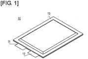
- FIG. 1 is an oblique view showing the exterior of a battery cell.
- FIG. 2 is a diagram showing a plan view and side view of the battery cell.
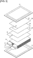
- FIG. 3 is an exploded oblique view of the battery cell.
- the battery cell 10 has a flattened rectangular shape, with a positive electrode lead 11 and a negative lead 12 exiting from the same end of an external packaging 13.
- the external packaging 13, for example, is produced by applying a resin coating to the surface of an aluminum sheet.
- the interior of the external packaging 13 contains electrolyte and an electricity-generating element (battery element) 15 whereby the charging and discharging reactions occur.
- the electricity-generating element 15 is formed by alternately layering positive electrodes 30 and negative electrodes 40, with sheet-form separators 20 interposed therebetween. In some cases, air, gas, or the like remains in the battery element 15 (separator 20) after the electricity-generating element 15 has been disposed in the external packaging 13, or after the electrolyte has been added.
- a positive active substance layer 32 is formed on both surfaces of a sheet-form positive electrode collector.
- the positive active substance layer 32 is not formed on the tab portions 34 of the positive electrodes 30.
- the respective tab portions 34 of the positive electrodes 30 are disposed at overlapping positions as seen from the layering direction in the electricity-generating element 15.
- the tab portions 34 connect with a positive electrode lead 11.
- a negative electrode active substance layer 42 is formed on both surfaces of a sheet-form negative electrode collector.
- the negative active substance layer 42 is not formed on the tab portions 44 of the negative electrodes 40.
- the respective tab portions 44 of the negative electrodes 40 are disposed at overlapping positions as seen from the direction of layering of the electricity-generating element 15 and are disposed so as not to overlap with the tab portions 34 of the positive electrodes 30.
- the tab portions 44 are connected to a negative electrode lead 12.
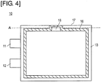
- FIG. 4 is a diagram showing the sealing part in the battery cell.
- the sealing part 16 indicated by the slanted lines in the drawing is shown for purposes of describing its position, but cannot actually be seen from outside the battery cell 10.
- the external packaging 13 of the battery cell 10 contains a battery element 15 between two sheets of rectangular laminated sheet (external packaging sheet).
- the packaging is formed so as to be sealed by a sealing part 16 that runs along each edge of the rectangular form.
- Adhesion of the external packaging 13 can be achieved, for example, by heat-fusing of the resin that coats the external packaging 13.
- the sealing part 16 is formed at a location that is at a prescribed separation from each edge of the battery cell 10. Specifically, the sealing part is smaller all around than the external shape of the battery cell 10.
- the sealing part 16 is formed in the shape of an open box so as to approach one portion of the edge 17.
- one edge of the battery cell 10 is used as a gas extraction opening 18 for discharging air or gas in the external packaging 13.
- the edge 17 of the battery cell 10 is cut off at the location indicated by the dotted line A in the drawing, and when this is done, the gas extraction opening 18 passes through the inner and outer parts of the external packaging 13. Gas or the like in the external packaging 13 is discharged through the gas extraction opening 18. Subsequently, the external packaging 13 is adhered in the portion of the gas extraction opening 18, thereby resealing the battery cell 10.
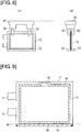
- FIG. 5 is a diagram showing the elements involved in transport and carrying of the battery cell.
- FIG. 5(A) shows a plan view of the elements of the battery cell 10.
- FIG. 5(B) shows the elements as viewed from the direction of arrow 5B in FIG. 5(A) .
- the battery cell 10 is transported by a transport device 50.
- the transport device 50 in this embodiment transports the battery cell 10 through the air with the battery cell suspended in a state in which the short edge of the rectangular form of the battery cell 10 is standing vertically.
- the transport device 50 for example, is a transport robot that transports the battery cell by sandwiching the upper part of the flat surface of the battery cell 10 from both sides with gripping parts 52.
- the transport device 50 transports the battery cells 10 to various processing or treatment steps, transfers the battery cells 10 to other devices, and removes the battery cells from other devices.
- Examples of other devices include receiving stands for temporarily carrying the battery cells 10, storage devices for storing the battery cells 10, and transport devices for transporting the battery cells 10 that employ methods other than those of the transport device 50.
- these may be processing devices or processing stands for carrying out prescribed processes on the battery cells 10. A case is described below in which the battery cell 10 is transferred to a receiving stand 60 shown in the bottom of the drawing.
- the receiving stand 60 has a support part 62 that supports the battery cell 10 from both surfaces.
- the battery cell 10 is transported over the receiving stand 60 by the transport device 50, and the battery cell 10 is inserted between the supports parts 62 of the receiving stand 60 when the transport device 50 approaches the receiving stand 60.
- the transport device 50 releases the gripping parts 52, the battery cell 10 is stored in the receiving stand 60.
- the transport device 50 approaches the receiving stand 60, and the battery cell 10 is gripped by the gripping parts 52. By raising the transport device 50, the battery cell 10 is removed from the receiving stand 60.
- the battery cell 10 is transported in a state of being positioned over the gas extraction opening 18 and is stored in the receiving stand 60 from the opposite edge from the gas extraction opening 18. Consequently, the edge of the battery cell 10 opposite the gas extraction opening 18 often contacts other devices such as the receiving stand 60.
- FIG. 6 is a flow chart showing the sequence of the battery reinforcement method.
- FIG. 7 is a diagram showing the elements involved in checking battery cell deformation.
- FIG. 8 is a diagram showing the elements involved in forming the reinforcing part.
- FIG. 9 is a diagram showing the reinforcing part formed in the battery cell.
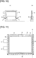
- FIG. 10 is a diagram showing the elements involved in rounding the reinforcing part.
- the battery cell 10 is transported by the transport device 50 to a prescribed position, and a check is performed to determine whether there is deformation such as bending at locations on the battery cell 10 to be reinforced (step S1).
- the sensor 70 shown in FIG. 7 detects deformation.
- the sensor 70 for example, is a pair of photoelectric sensors which can check for deformation of the external packaging 13 of the battery cell 10 by using one to detect the amount of light that has been emitted from the other.
- the external packaging 13, as shown in FIG. 5 often contacts other devices at the edge that is positioned downward in the drawing, and, in particular, is often deformed at the corners. Consequently, for example, it is desirable to detect bending at the corner portions of the external packaging 13 represented by the dotted lines in FIG. 7 .
- step S2 When bending of the external packaging 13 is detected by the sensor 70 (step S1: YES), deformation is corrected (step S2). Bend correction, for example, involves a pressing roller that evens out the external packaging 13 by pressing so as to be perfectly straight. However, deformation of the external packaging 13 may be corrected by any method.
- step S3 the battery cell 10 is then subjected to reinforcing part formation.
- the lower part of the external packaging 13 of the battery cell 10 is thermally fused by a heat-fusing device 72.
- the heat-fusing device 72 has a pair of blocks that abut the part of the external packaging 13 where the reinforcing part is to be formed, pressing it while heating from both sides, thereby fusing the resin of the external packaging 13. As shown in FIG.
- the reinforcing part 80 is formed outwards from the sealing part 16 of the battery cell 10 on an edge 19 that is different from the edge 17 on which the gas extraction opening 18 has been formed.
- the sealing part 16 that seals the external packaging 13 can be formed by heat-fusing
- the reinforcing part 80 can be formed by heat-fusing with a different degree of precision than used for the sealing part 16.
- the sealing part 16 can be formed by high-precision heat-fusing
- the reinforcing part 80 can be formed by comparatively low-precision heat-fusing.
- step S4 the corners of the reinforcing part 80 that has been formed in the battery cell 10 are rounded (step S4).
- the reinforcing part 80 as shown in FIG. 10 , is rounded using scissors 74.
- the scissors 74 approach the corners of the battery cell 10 that is carried on the receiving stand 60 or the like, and the corners are cut off. The portions drawn in black in FIGS. 9 and 10 are cut away.
- step S4 the battery cell 10 is transported to various devices for processing or the like. At this time, the battery cell 10 is placed in and removed from the receiving stand 60 or storage. After completion of the primary and other processes for the battery cell 10, but prior to shipping the battery cell 10 product, the reinforcing part 80 is cut away from the battery cell 10 (step S5). The reinforcing part 80 is cut away at the location indicated by the dotted line B in FIG. 9 .
- a reinforcing part 80 is formed on the edge 19 that is different from the edge 17 on which the gas extraction opening 18 that is used for gas discharge has been formed.
- the edge 19 that is not the edge 17, as described above, often comes into contact with other devices such as transport devices 50 or receiving stands 60 when transporting the battery cell 10 or when supporting the battery cells for processing. Consequently, by reinforcing the edge 19, deformation of the external packaging 13 of the battery cell 10 due to contact with other devices can be prevented.
- the reinforcing part 80 can be formed without the addition of other members, and so the prevention of deformation can be realized at low cost without excess costs required for the reinforcing part 80.
- the reinforcing part 80 is formed outwards and separately from the laminated sheet sealing part 16 of the external packaging 13. Consequently, the reinforcing part 80 can be formed with different standards or at a different precision from the sealing part 16. Because the reinforcing part 80 is formed separate from the sealing part 16, the sealing part 16 can be protected by the reinforcing part 80 during transport of the battery cell 10 or in other circumstances.
- sealing part 16 and the reinforcing part 80 can be achieved separately from the other by heat-fusing of the resin on the laminated sheet. Consequently, the sealing part 16 and the reinforcing part 80 can be formed separately using laminated sheets having the same configuration.
- deformation of the external packaging 13 is checked with the sensor 70, and thus deformation of the edge can be reliably detected.
- the reinforcing part 80 is formed on the edge 19 of the battery cell 10 that is in contact with other devices such as the receiving stand 60, and thus deformation of the external packaging 13 of the battery cell 10 due to contact with other devices can be prevented.
- edge 19 that has been reinforced by the reinforcing part 80 has rounded corners, distribution of load to the corners and deformation of the edge 19 can be prevented when the battery cell 10 is inserted from the reinforced edge 19 into other devices such as a receiving stand 60.
- the reinforcing part 80 is provided in a step such as processing of the battery cell 10, and deformation of the external packaging 13 of the battery cell 10 is prevented, with the reinforcing part 80 being then cut away in the end. Consequently, the reinforcing part 80 that has incurred some scratching in processing or other steps while reinforcing the battery cell will not remain on the battery cell 10 in the final product. A battery cell 10 is thus obtained that has absolutely no scratching.
- FIG. 11 is a diagram showing a battery cell in which another reinforcing part has been formed.
- the reinforcing part 80 was formed along an edge 19 of the battery cell 10, but the invention is not limited thereby.
- reinforcing parts 81, 82 may be formed on the edges that stand vertically.
- the method for forming the reinforcing parts 81, 82 may be the same as described above, i.e., formation by thermocompression-bonding of the resin in the laminated sheets.
- the reinforcing part 81 Prior to shipping the battery cell 10, the reinforcing part 81 may be cut off at the location indicated by the dotted line C.
- a reinforcing part 82 was formed also on the edge where the positive lead 11 and the negative lead 12 exit, but the reinforcing part 82 may remain as it cannot be cut off.
- the positive electrode lead 11 and the like are present on the same side as the reinforcing part 82, and excessive damage will not occur, so there will not be any problems with leaving the reinforcing part 82.
Landscapes
- Chemical & Material Sciences (AREA)
- Chemical Kinetics & Catalysis (AREA)
- Electrochemistry (AREA)
- General Chemical & Material Sciences (AREA)
- Inorganic Chemistry (AREA)
- Sealing Battery Cases Or Jackets (AREA)
Claims (10)
- Batterieverstärkungsverfahren zum Verstärken einer rechteckigen Batteriezelle (10), in der ein Batterieelement (15) in einer rechteckigen Außenverpackung (13) angeordnet ist, wobei das Verfahren das Bilden der Außenverpackung (13) durch Einschließen des Batterieelements (15) zwischen zwei rechteckigen Außenverpackungslagen, und Versiegeln der rechteckigen Außenverpackungslagen mit einem Versiegelungselement (16) umfasst, das um einen gesamten Umfang des Batterieelements (15) verläuft, um die rechteckige Außenverpackung (13) zu bilden, wobei die rechteckige Außenverpackung (13) vier Seiten aufweist, jede der Seiten einen Rand aufweist, das Versiegelungselement (16) von den Rändern von drei der Seiten getrennt ist, sodass das Versiegelungselement (16) zwischen dem Batterieelement (15) und den Rändern der drei Seiten der rechteckigen Außenverpackung (13) angeordnet ist; und einen Schritt des Bildens eines Verstärkungselements (80; 80, 81, 82) an zumindest einer der drei Seiten der rechteckigen Außenverpackung (13) umfasst, sodass ein länglicher Spalt zwischen dem Versiegelungselement und dem Verstärkungselement (80; 80, 81, 82) vorhanden ist, wobei das Verstärkungselement (80; 80, 81, 82) in einem Bereich zwischen dem Versiegelungselement (16) und dem Rand der zumindest einen der drei Seiten der rechteckigen Außenverpackung (13) angeordnet ist, von dem das Versiegelungselement (16) getrennt ist, wobei sich der Spalt parallel zum Rand der zumindest einen der drei Seiten erstreckt, sodass das Verstärkungselement (80; 80, 81, 82) durch den Spalt vom Versiegelungselement (16) getrennt ist und das Versiegelungselement (16) nicht überlappt,
wobei die Außenverpackungslagen durch Beschichten einer Metallfolie mit einem Harz gebildet werden, und
das Versiegelungselement (16) und das Verstärkungselement (80; 80, 81, 82) unabhängig voneinander durch Thermokompressionsbonden des Harzes, das die beiden Außenverpackungslagen ummantelt, gebildet werden, wobei
das Verstärkungselement (80; 80, 81, 82) an zumindest einem Teil eines Rands der Außenverpackungslage ausgebildet ist, der sich von einem Rand der rechteckigen Form unterscheidet, die zum Abgeben von Gas verwendet wird. - Batterieverstärkungsverfahren nach Anspruch 1, ferner umfassend einen Schritt zum Korrigieren einer Verformung eines Abschnitts des Rands, an dem das Verstärkungselement (80; 80, 81, 82) ausgebildet werden soll, wobei der Verformungskorrekturschritt vor dem Schritt zum Formen des Verstärkungselements (80; 80, 81, 82) an zumindest einem Teil eines Rands der Batteriezelle (10) ausgeführt wird.
- Batterieverstärkungsverfahren nach Anspruch 1 oder 2, ferner umfassend einen Schritt zum Erfassen einer Verformung des Abschnitts des Rands, an dem das Verstärkungselement (80; 80, 81, 82) ausgebildet werden soll, wobei der Verformungserfassungsschritt vor dem Schritt zum Ausbilden des Verstärkungselements (80; 80, 81, 82) an zumindest einem Teil eines Rands der Batteriezelle (10) ausgeführt wird.
- Batterieverstärkungsverfahren nach einem der Ansprüche 1-3, wobei das Verstärkungselement (80; 80, 81, 82) an einem Rand der Batteriezelle ausgebildet wird, der mit einer anderen Vorrichtung in Kontakt sein soll, wenn die Batteriezelle (10) in die andere Vorrichtung überführt oder von dieser aufgenommen wird.
- Batterieverstärkungsverfahren nach einem der Ansprüche 1-4, das ferner einen Schritt zum Abrunden der Ecken eines Rands umfasst, der durch das Verstärkungselement (80; 80, 81, 82) verstärkt wurde.
- Batterieverstärkungsverfahren nach einem der Ansprüche 1-5, das ferner einen Schritt zum Schneiden eines Abschnitts des Rands der Batteriezelle (10) umfasst, an dem das Verstärkungselement (80; 81) ausgebildet wurde.
- Batterieverstärkungsverfahren nach einem der vorhergehenden Ansprüche, wobei das Formen des Verstärkungselements (80; 80, 81, 82) nach dem Formen des Versiegelungselements (16) durchgeführt wird.
- Batterieverstärkungsverfahren nach einem der vorhergehenden Ansprüche, wobei das Versiegelungselement (16) so ausgebildet ist, dass es eine offene Kastenform aufweist, die sich einem Außenumfang eines Rands der rechteckigen Außenverpackung (13) nähert, der sich vom zumindest einen Rand, an dem das Verstärkungselement (80; 80, 81, 82) ausgebildet ist, unterscheidet, wobei sich die offene Kastenform nach innen in Richtung einer Mitte der rechteckigen Batteriezelle (10) öffnet.
- Batterieverstärkungsverfahren nach Anspruch 8, wobei das Verstärkungselement (80) an einem der Ränder der rechteckigen Außenverpackung (13) ausgebildet ist, und die offene Kastenform des Versiegelungselements (16) an einem anderen Rand der rechteckigen Verpackung ausgebildet ist, die dem Rand, an dem das Verstärkungselement (80) ausgebildet ist, gegenüberliegt.
- Batterieverstärkungsverfahren nach einem der vorhergehenden Ansprüche, wobei das Thermokompressionsbonden, das während der Bildung des Versiegelungselements (16) und des Verstärkungselements ausgeführt wird, ein Wärmeschmelzen des Harzes umfasst, das die beiden Außenverpackungslagen ummantelt, wobei das Versiegelungselement (16) durch ein Wärmeschmelzen mit höherer Präzision als das Verstärkungselement (80; 80, 81, 82) gebildet wird.
Applications Claiming Priority (2)
| Application Number | Priority Date | Filing Date | Title |
|---|---|---|---|
| JP2012028515A JP5909378B2 (ja) | 2012-02-13 | 2012-02-13 | 電池補強方法 |
| PCT/JP2013/053381 WO2013122097A1 (ja) | 2012-02-13 | 2013-02-13 | 電池補強方法 |
Publications (3)
| Publication Number | Publication Date |
|---|---|
| EP2816631A1 EP2816631A1 (de) | 2014-12-24 |
| EP2816631A4 EP2816631A4 (de) | 2015-07-29 |
| EP2816631B1 true EP2816631B1 (de) | 2021-03-24 |
Family
ID=48984206
Family Applications (1)
| Application Number | Title | Priority Date | Filing Date |
|---|---|---|---|
| EP13748485.3A Active EP2816631B1 (de) | 2012-02-13 | 2013-02-13 | Batterieverstärkungsverfahren |
Country Status (5)
| Country | Link |
|---|---|
| US (1) | US9553285B2 (de) |
| EP (1) | EP2816631B1 (de) |
| JP (1) | JP5909378B2 (de) |
| CN (1) | CN104115302B (de) |
| WO (1) | WO2013122097A1 (de) |
Families Citing this family (2)
| Publication number | Priority date | Publication date | Assignee | Title |
|---|---|---|---|---|
| US9837682B1 (en) | 2016-08-29 | 2017-12-05 | Microsoft Technology Licensing, Llc | Variable layer thickness in curved battery cell |
| KR102779619B1 (ko) * | 2020-11-09 | 2025-03-10 | 주식회사 엘지에너지솔루션 | 이차 전지 |
Family Cites Families (12)
| Publication number | Priority date | Publication date | Assignee | Title |
|---|---|---|---|---|
| GB2087779B (en) * | 1980-11-20 | 1985-05-15 | Rhodes Joseph Ltd | Metal trimmer |
| JPH07183357A (ja) | 1993-12-22 | 1995-07-21 | Dainippon Screen Mfg Co Ltd | 基板配列ピッチ変換装置 |
| JP3709134B2 (ja) * | 2000-11-22 | 2005-10-19 | 松下電器産業株式会社 | 角形電池 |
| WO2005108945A1 (en) * | 2004-05-12 | 2005-11-17 | Pirelli Tyre S.P.A. | Method for determining a force at the hub of a wheel of a vehicle whilst traveling and wheel suitable for allowing said method to be carried out |
| JP4744816B2 (ja) * | 2004-06-03 | 2011-08-10 | 株式会社東芝 | 薄型非水電解質二次電池 |
| WO2006098242A1 (ja) * | 2005-03-17 | 2006-09-21 | Nec Corporation | フィルム外装電気デバイスおよびその製造方法 |
| JP5108411B2 (ja) * | 2007-08-03 | 2012-12-26 | パナソニック株式会社 | 電池缶およびその製造方法並びに製造装置 |
| US20090169977A1 (en) * | 2007-12-31 | 2009-07-02 | Apple Inc. | Systems and methods for monitoring and responding to forces influencing a battery |
| DE102008047615A1 (de) * | 2008-09-17 | 2010-04-15 | Li-Tec Battery Gmbh | Akkumulator |
| JP2010198988A (ja) * | 2009-02-26 | 2010-09-09 | Sumitomo Chemical Co Ltd | フィルムケース型蓄電デバイス |
| US8771866B2 (en) * | 2010-03-30 | 2014-07-08 | Samsung Sdi Co., Ltd. | Pouch type secondary battery and the fabrication method thereof |
| JP2012204002A (ja) * | 2011-03-23 | 2012-10-22 | Nec Tokin Corp | 蓄電デバイス |
-
2012
- 2012-02-13 JP JP2012028515A patent/JP5909378B2/ja active Active
-
2013
- 2013-02-13 US US14/376,649 patent/US9553285B2/en active Active
- 2013-02-13 WO PCT/JP2013/053381 patent/WO2013122097A1/ja not_active Ceased
- 2013-02-13 EP EP13748485.3A patent/EP2816631B1/de active Active
- 2013-02-13 CN CN201380008850.XA patent/CN104115302B/zh active Active
Non-Patent Citations (1)
| Title |
|---|
| None * |
Also Published As
| Publication number | Publication date |
|---|---|
| CN104115302A (zh) | 2014-10-22 |
| US20150026969A1 (en) | 2015-01-29 |
| EP2816631A4 (de) | 2015-07-29 |
| JP2013165038A (ja) | 2013-08-22 |
| EP2816631A1 (de) | 2014-12-24 |
| CN104115302B (zh) | 2017-12-01 |
| WO2013122097A1 (ja) | 2013-08-22 |
| JP5909378B2 (ja) | 2016-04-26 |
| US9553285B2 (en) | 2017-01-24 |
Similar Documents
| Publication | Publication Date | Title |
|---|---|---|
| EP2985805B1 (de) | Gekrümmte-batterie und verfahren zur herstellung davon | |
| EP3588653B1 (de) | Verfahren zur herstellung einer monozelle | |
| EP2884560B1 (de) | Flexible Sekundärbatterie | |
| KR102042018B1 (ko) | 실링 라인이 형성되어 있는 외주면 실링부를 포함하는 전지셀, 및 이를 생산하기 위한 전지셀 실링장치 | |
| EP4120410A1 (de) | Vorrichtung und verfahren zur herstellung von einheitszellen | |
| JP2011181395A (ja) | 積層型リチウムイオン二次電池及びその製造方法と製造装置 | |
| US10483505B2 (en) | Sheet attachment device for battery packs | |
| US20200373535A1 (en) | Pouch, Secondary Battery Comprising the Same, and Method for Manufacturing the Secondary Battery | |
| EP3731322A1 (de) | Verfahren zur herstellung einer elektrodenanordnung und verfahren zur herstellung einer sekundärbatterie | |
| KR102222111B1 (ko) | 이차 전지 | |
| EP2816631B1 (de) | Batterieverstärkungsverfahren | |
| KR101840859B1 (ko) | 전극조립체 고정용 접착부재의 부가 장치 | |
| US20150013150A1 (en) | Bus bar attachment device and bus bar attachment method | |
| JP7024188B2 (ja) | 電極組立体の製造方法 | |
| JP2012185976A (ja) | 積層型電池 | |
| US11967734B2 (en) | Electrode assembly, secondary battery comprising the same, method for manufacturing secondary battery, and battery pack | |
| KR20130112773A (ko) | 탭 리드용 곤포 용기 및 탭 리드 곤포품 | |
| KR20200093956A (ko) | 전극조립체 가열유닛, 그를 포함하는 라미네이션장치 및 방법 | |
| EP4181256A1 (de) | Vorrichtung und verfahren für batterielaminierungsverfahren | |
| JP2019057476A (ja) | 蓄電モジュールの製造方法及び製造装置 | |
| EP4089809A1 (de) | Batteriezelle und herstellungsvorrichtung dafür | |
| CN120917595A (zh) | 电极单元及其制造方法 | |
| KR101359382B1 (ko) | 배터리 셀 | |
| KR20220052774A (ko) | 제1 전극 제조장치, 그를 포함하는 전극조립체 제조설비 및 제조방법 | |
| KR20220136839A (ko) | 파우치의 길이에 따라 위치 조절이 가능한 전지셀 이송용 장치 |
Legal Events
| Date | Code | Title | Description |
|---|---|---|---|
| PUAI | Public reference made under article 153(3) epc to a published international application that has entered the european phase |
Free format text: ORIGINAL CODE: 0009012 |
|
| 17P | Request for examination filed |
Effective date: 20140801 |
|
| AK | Designated contracting states |
Kind code of ref document: A1 Designated state(s): AL AT BE BG CH CY CZ DE DK EE ES FI FR GB GR HR HU IE IS IT LI LT LU LV MC MK MT NL NO PL PT RO RS SE SI SK SM TR |
|
| AX | Request for extension of the european patent |
Extension state: BA ME |
|
| DAX | Request for extension of the european patent (deleted) | ||
| RA4 | Supplementary search report drawn up and despatched (corrected) |
Effective date: 20150625 |
|
| RIC1 | Information provided on ipc code assigned before grant |
Ipc: H01M 2/06 20060101ALI20150619BHEP Ipc: H01M 2/02 20060101AFI20150619BHEP |
|
| STAA | Information on the status of an ep patent application or granted ep patent |
Free format text: STATUS: EXAMINATION IS IN PROGRESS |
|
| 17Q | First examination report despatched |
Effective date: 20171220 |
|
| RAP1 | Party data changed (applicant data changed or rights of an application transferred) |
Owner name: ENVISION AESC JAPAN LTD. |
|
| GRAP | Despatch of communication of intention to grant a patent |
Free format text: ORIGINAL CODE: EPIDOSNIGR1 |
|
| STAA | Information on the status of an ep patent application or granted ep patent |
Free format text: STATUS: GRANT OF PATENT IS INTENDED |
|
| INTG | Intention to grant announced |
Effective date: 20201021 |
|
| GRAS | Grant fee paid |
Free format text: ORIGINAL CODE: EPIDOSNIGR3 |
|
| GRAA | (expected) grant |
Free format text: ORIGINAL CODE: 0009210 |
|
| STAA | Information on the status of an ep patent application or granted ep patent |
Free format text: STATUS: THE PATENT HAS BEEN GRANTED |
|
| AK | Designated contracting states |
Kind code of ref document: B1 Designated state(s): AL AT BE BG CH CY CZ DE DK EE ES FI FR GB GR HR HU IE IS IT LI LT LU LV MC MK MT NL NO PL PT RO RS SE SI SK SM TR |
|
| REG | Reference to a national code |
Ref country code: GB Ref legal event code: FG4D |
|
| REG | Reference to a national code |
Ref country code: CH Ref legal event code: EP |
|
| REG | Reference to a national code |
Ref country code: DE Ref legal event code: R096 Ref document number: 602013076437 Country of ref document: DE |
|
| REG | Reference to a national code |
Ref country code: IE Ref legal event code: FG4D |
|
| REG | Reference to a national code |
Ref country code: AT Ref legal event code: REF Ref document number: 1375408 Country of ref document: AT Kind code of ref document: T Effective date: 20210415 |
|
| REG | Reference to a national code |
Ref country code: LT Ref legal event code: MG9D |
|
| PG25 | Lapsed in a contracting state [announced via postgrant information from national office to epo] |
Ref country code: GR Free format text: LAPSE BECAUSE OF FAILURE TO SUBMIT A TRANSLATION OF THE DESCRIPTION OR TO PAY THE FEE WITHIN THE PRESCRIBED TIME-LIMIT Effective date: 20210625 Ref country code: FI Free format text: LAPSE BECAUSE OF FAILURE TO SUBMIT A TRANSLATION OF THE DESCRIPTION OR TO PAY THE FEE WITHIN THE PRESCRIBED TIME-LIMIT Effective date: 20210324 Ref country code: HR Free format text: LAPSE BECAUSE OF FAILURE TO SUBMIT A TRANSLATION OF THE DESCRIPTION OR TO PAY THE FEE WITHIN THE PRESCRIBED TIME-LIMIT Effective date: 20210324 Ref country code: BG Free format text: LAPSE BECAUSE OF FAILURE TO SUBMIT A TRANSLATION OF THE DESCRIPTION OR TO PAY THE FEE WITHIN THE PRESCRIBED TIME-LIMIT Effective date: 20210624 Ref country code: NO Free format text: LAPSE BECAUSE OF FAILURE TO SUBMIT A TRANSLATION OF THE DESCRIPTION OR TO PAY THE FEE WITHIN THE PRESCRIBED TIME-LIMIT Effective date: 20210624 |
|
| PG25 | Lapsed in a contracting state [announced via postgrant information from national office to epo] |
Ref country code: LV Free format text: LAPSE BECAUSE OF FAILURE TO SUBMIT A TRANSLATION OF THE DESCRIPTION OR TO PAY THE FEE WITHIN THE PRESCRIBED TIME-LIMIT Effective date: 20210324 Ref country code: RS Free format text: LAPSE BECAUSE OF FAILURE TO SUBMIT A TRANSLATION OF THE DESCRIPTION OR TO PAY THE FEE WITHIN THE PRESCRIBED TIME-LIMIT Effective date: 20210324 Ref country code: SE Free format text: LAPSE BECAUSE OF FAILURE TO SUBMIT A TRANSLATION OF THE DESCRIPTION OR TO PAY THE FEE WITHIN THE PRESCRIBED TIME-LIMIT Effective date: 20210324 |
|
| REG | Reference to a national code |
Ref country code: NL Ref legal event code: MP Effective date: 20210324 |
|
| REG | Reference to a national code |
Ref country code: AT Ref legal event code: MK05 Ref document number: 1375408 Country of ref document: AT Kind code of ref document: T Effective date: 20210324 |
|
| PG25 | Lapsed in a contracting state [announced via postgrant information from national office to epo] |
Ref country code: NL Free format text: LAPSE BECAUSE OF FAILURE TO SUBMIT A TRANSLATION OF THE DESCRIPTION OR TO PAY THE FEE WITHIN THE PRESCRIBED TIME-LIMIT Effective date: 20210324 |
|
| PG25 | Lapsed in a contracting state [announced via postgrant information from national office to epo] |
Ref country code: SM Free format text: LAPSE BECAUSE OF FAILURE TO SUBMIT A TRANSLATION OF THE DESCRIPTION OR TO PAY THE FEE WITHIN THE PRESCRIBED TIME-LIMIT Effective date: 20210324 Ref country code: AT Free format text: LAPSE BECAUSE OF FAILURE TO SUBMIT A TRANSLATION OF THE DESCRIPTION OR TO PAY THE FEE WITHIN THE PRESCRIBED TIME-LIMIT Effective date: 20210324 Ref country code: LT Free format text: LAPSE BECAUSE OF FAILURE TO SUBMIT A TRANSLATION OF THE DESCRIPTION OR TO PAY THE FEE WITHIN THE PRESCRIBED TIME-LIMIT Effective date: 20210324 Ref country code: CZ Free format text: LAPSE BECAUSE OF FAILURE TO SUBMIT A TRANSLATION OF THE DESCRIPTION OR TO PAY THE FEE WITHIN THE PRESCRIBED TIME-LIMIT Effective date: 20210324 Ref country code: EE Free format text: LAPSE BECAUSE OF FAILURE TO SUBMIT A TRANSLATION OF THE DESCRIPTION OR TO PAY THE FEE WITHIN THE PRESCRIBED TIME-LIMIT Effective date: 20210324 |
|
| PG25 | Lapsed in a contracting state [announced via postgrant information from national office to epo] |
Ref country code: ES Free format text: LAPSE BECAUSE OF FAILURE TO SUBMIT A TRANSLATION OF THE DESCRIPTION OR TO PAY THE FEE WITHIN THE PRESCRIBED TIME-LIMIT Effective date: 20210324 Ref country code: PL Free format text: LAPSE BECAUSE OF FAILURE TO SUBMIT A TRANSLATION OF THE DESCRIPTION OR TO PAY THE FEE WITHIN THE PRESCRIBED TIME-LIMIT Effective date: 20210324 Ref country code: PT Free format text: LAPSE BECAUSE OF FAILURE TO SUBMIT A TRANSLATION OF THE DESCRIPTION OR TO PAY THE FEE WITHIN THE PRESCRIBED TIME-LIMIT Effective date: 20210726 Ref country code: SK Free format text: LAPSE BECAUSE OF FAILURE TO SUBMIT A TRANSLATION OF THE DESCRIPTION OR TO PAY THE FEE WITHIN THE PRESCRIBED TIME-LIMIT Effective date: 20210324 Ref country code: RO Free format text: LAPSE BECAUSE OF FAILURE TO SUBMIT A TRANSLATION OF THE DESCRIPTION OR TO PAY THE FEE WITHIN THE PRESCRIBED TIME-LIMIT Effective date: 20210324 Ref country code: IS Free format text: LAPSE BECAUSE OF FAILURE TO SUBMIT A TRANSLATION OF THE DESCRIPTION OR TO PAY THE FEE WITHIN THE PRESCRIBED TIME-LIMIT Effective date: 20210724 |
|
| REG | Reference to a national code |
Ref country code: DE Ref legal event code: R097 Ref document number: 602013076437 Country of ref document: DE |
|
| PG25 | Lapsed in a contracting state [announced via postgrant information from national office to epo] |
Ref country code: AL Free format text: LAPSE BECAUSE OF FAILURE TO SUBMIT A TRANSLATION OF THE DESCRIPTION OR TO PAY THE FEE WITHIN THE PRESCRIBED TIME-LIMIT Effective date: 20210324 Ref country code: DK Free format text: LAPSE BECAUSE OF FAILURE TO SUBMIT A TRANSLATION OF THE DESCRIPTION OR TO PAY THE FEE WITHIN THE PRESCRIBED TIME-LIMIT Effective date: 20210324 |
|
| PLBE | No opposition filed within time limit |
Free format text: ORIGINAL CODE: 0009261 |
|
| STAA | Information on the status of an ep patent application or granted ep patent |
Free format text: STATUS: NO OPPOSITION FILED WITHIN TIME LIMIT |
|
| PG25 | Lapsed in a contracting state [announced via postgrant information from national office to epo] |
Ref country code: SI Free format text: LAPSE BECAUSE OF FAILURE TO SUBMIT A TRANSLATION OF THE DESCRIPTION OR TO PAY THE FEE WITHIN THE PRESCRIBED TIME-LIMIT Effective date: 20210324 |
|
| 26N | No opposition filed |
Effective date: 20220104 |
|
| PG25 | Lapsed in a contracting state [announced via postgrant information from national office to epo] |
Ref country code: IS Free format text: LAPSE BECAUSE OF FAILURE TO SUBMIT A TRANSLATION OF THE DESCRIPTION OR TO PAY THE FEE WITHIN THE PRESCRIBED TIME-LIMIT Effective date: 20210724 |
|
| PG25 | Lapsed in a contracting state [announced via postgrant information from national office to epo] |
Ref country code: MC Free format text: LAPSE BECAUSE OF FAILURE TO SUBMIT A TRANSLATION OF THE DESCRIPTION OR TO PAY THE FEE WITHIN THE PRESCRIBED TIME-LIMIT Effective date: 20210324 |
|
| REG | Reference to a national code |
Ref country code: CH Ref legal event code: PL |
|
| REG | Reference to a national code |
Ref country code: BE Ref legal event code: MM Effective date: 20220228 |
|
| PG25 | Lapsed in a contracting state [announced via postgrant information from national office to epo] |
Ref country code: LU Free format text: LAPSE BECAUSE OF NON-PAYMENT OF DUE FEES Effective date: 20220213 |
|
| PG25 | Lapsed in a contracting state [announced via postgrant information from national office to epo] |
Ref country code: LI Free format text: LAPSE BECAUSE OF NON-PAYMENT OF DUE FEES Effective date: 20220228 Ref country code: IT Free format text: LAPSE BECAUSE OF FAILURE TO SUBMIT A TRANSLATION OF THE DESCRIPTION OR TO PAY THE FEE WITHIN THE PRESCRIBED TIME-LIMIT Effective date: 20210324 Ref country code: IE Free format text: LAPSE BECAUSE OF NON-PAYMENT OF DUE FEES Effective date: 20220213 Ref country code: CH Free format text: LAPSE BECAUSE OF NON-PAYMENT OF DUE FEES Effective date: 20220228 |
|
| PG25 | Lapsed in a contracting state [announced via postgrant information from national office to epo] |
Ref country code: BE Free format text: LAPSE BECAUSE OF NON-PAYMENT OF DUE FEES Effective date: 20220228 |
|
| P01 | Opt-out of the competence of the unified patent court (upc) registered |
Effective date: 20230330 |
|
| PG25 | Lapsed in a contracting state [announced via postgrant information from national office to epo] |
Ref country code: HU Free format text: LAPSE BECAUSE OF FAILURE TO SUBMIT A TRANSLATION OF THE DESCRIPTION OR TO PAY THE FEE WITHIN THE PRESCRIBED TIME-LIMIT; INVALID AB INITIO Effective date: 20130213 |
|
| PG25 | Lapsed in a contracting state [announced via postgrant information from national office to epo] |
Ref country code: MK Free format text: LAPSE BECAUSE OF FAILURE TO SUBMIT A TRANSLATION OF THE DESCRIPTION OR TO PAY THE FEE WITHIN THE PRESCRIBED TIME-LIMIT Effective date: 20210324 Ref country code: CY Free format text: LAPSE BECAUSE OF FAILURE TO SUBMIT A TRANSLATION OF THE DESCRIPTION OR TO PAY THE FEE WITHIN THE PRESCRIBED TIME-LIMIT Effective date: 20210324 |
|
| PG25 | Lapsed in a contracting state [announced via postgrant information from national office to epo] |
Ref country code: MT Free format text: LAPSE BECAUSE OF FAILURE TO SUBMIT A TRANSLATION OF THE DESCRIPTION OR TO PAY THE FEE WITHIN THE PRESCRIBED TIME-LIMIT Effective date: 20210324 |
|
| PGFP | Annual fee paid to national office [announced via postgrant information from national office to epo] |
Ref country code: GB Payment date: 20241227 Year of fee payment: 13 |
|
| PGFP | Annual fee paid to national office [announced via postgrant information from national office to epo] |
Ref country code: FR Payment date: 20241223 Year of fee payment: 13 |
|
| PGFP | Annual fee paid to national office [announced via postgrant information from national office to epo] |
Ref country code: DE Payment date: 20241224 Year of fee payment: 13 |