EP2816162A1 - Spülenflanschanordnung mit Gewinde zur Installation eines Lebensmittelabfallentsorgers in einer Spüle - Google Patents
Spülenflanschanordnung mit Gewinde zur Installation eines Lebensmittelabfallentsorgers in einer Spüle Download PDFInfo
- Publication number
- EP2816162A1 EP2816162A1 EP14170420.5A EP14170420A EP2816162A1 EP 2816162 A1 EP2816162 A1 EP 2816162A1 EP 14170420 A EP14170420 A EP 14170420A EP 2816162 A1 EP2816162 A1 EP 2816162A1
- Authority
- EP
- European Patent Office
- Prior art keywords
- flange
- threaded
- mounting
- sink
- upper mounting
- Prior art date
- Legal status (The legal status is an assumption and is not a legal conclusion. Google has not performed a legal analysis and makes no representation as to the accuracy of the status listed.)
- Granted
Links
Images

Classifications
-
- F—MECHANICAL ENGINEERING; LIGHTING; HEATING; WEAPONS; BLASTING
- F16—ENGINEERING ELEMENTS AND UNITS; GENERAL MEASURES FOR PRODUCING AND MAINTAINING EFFECTIVE FUNCTIONING OF MACHINES OR INSTALLATIONS; THERMAL INSULATION IN GENERAL
- F16L—PIPES; JOINTS OR FITTINGS FOR PIPES; SUPPORTS FOR PIPES, CABLES OR PROTECTIVE TUBING; MEANS FOR THERMAL INSULATION IN GENERAL
- F16L15/00—Screw-threaded joints; Forms of screw-threads for such joints
- F16L15/006—Screw-threaded joints; Forms of screw-threads for such joints with straight threads
-
- E—FIXED CONSTRUCTIONS
- E03—WATER SUPPLY; SEWERAGE
- E03C—DOMESTIC PLUMBING INSTALLATIONS FOR FRESH WATER OR WASTE WATER; SINKS
- E03C1/00—Domestic plumbing installations for fresh water or waste water; Sinks
- E03C1/12—Plumbing installations for waste water; Basins or fountains connected thereto; Sinks
- E03C1/26—Object-catching inserts or similar devices for waste pipes or outlets
- E03C1/266—Arrangement of disintegrating apparatus in waste pipes or outlets; Disintegrating apparatus specially adapted for installation in waste pipes or outlets
- E03C1/2665—Disintegrating apparatus specially adapted for installation in waste pipes or outlets
-
- B—PERFORMING OPERATIONS; TRANSPORTING
- B02—CRUSHING, PULVERISING, OR DISINTEGRATING; PREPARATORY TREATMENT OF GRAIN FOR MILLING
- B02C—CRUSHING, PULVERISING, OR DISINTEGRATING IN GENERAL; MILLING GRAIN
- B02C23/00—Auxiliary methods or auxiliary devices or accessories specially adapted for crushing or disintegrating not provided for in preceding groups or not specially adapted to apparatus covered by a single preceding group
- B02C23/18—Adding fluid, other than for crushing or disintegrating by fluid energy
- B02C23/36—Adding fluid, other than for crushing or disintegrating by fluid energy the crushing or disintegrating zone being submerged in liquid
Definitions
- the present disclosure relates generally to food waste disposers, and more particularly, to mount systems therefor.
- a conventional food waste disposer of the type for under sink mounting that is mounted to a sink, such as a kitchen sink, includes a food conveying section, a motor section, and a grinding section disposed between the food conveying section and the motor section.
- the food conveying section includes a housing that forms an inlet for receiving food waste and water.
- the food conveying section conveys the food waste to the grinding section, and the motor section includes a motor imparting rotational movement to a motor shaft to operate the grinding mechanism.
- the grinding section in which comminution occurs typically has a rotating shredder plate with lugs and a stationary grind ring received in a housing of the grinding section.
- the motor turns the rotating shredder plate and the lugs force the food waste against the grind ring where it is broken down into small pieces. Once the particles are small enough to pass out of the grinding mechanism, they are flushed out into the household plumbing. Size control is primarily achieved through controlling the size of the gap through which the food particles must pass.
- the housing of the grinding section and the housing of the food conveying section are integrally formed as a single housing. In other cases, they are not. Such a prior art food waste disposer is disclosed in U.S. U.S. Patent No.
- the food waste disposer may be mounted in a well-known manner in the drain opening of a sink using mounting members of the type disclosed in U.S. Pat. No. 3,025,007 , which is incorporated herein by reference in its entirety.
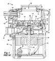
- Fig. 1 depicts a prior art food waste disposer 100 which is similar to the prior art food waste disposer described in US 7,360,729 and US 7,360,729 is incorporated by reference herein in its entirety.
- the disposer includes an upper food conveying section 102, a central grinding section 104 and a motor section 106, which may include a variable speed motor. It should be understood that motor section 106 could also include a fixed speed motor, such as an induction motor.
- the grinding section 104 is disposed between the food conveying section 102 and the motor section 106.
- the food conveying section 102 conveys the food waste to the grinding section 104.
- the food conveying section 102 includes an inlet housing 108 and a conveying housing 110.
- the inlet housing 108 has an inlet 109 at the upper end of the food waste disposer 100 for receiving food waste and water. Inlet 109 is surrounded by a gasket 111.
- the inlet housing 108 is attached to the conveying housing 110, such as by an antivibration mount 113.
- the conveying housing 110 has an opening 142 to receive a dishwasher inlet 144.
- the dishwasher inlet is used to pass water from a dishwasher (not shown).
- the inlet housing 108 and conveying housing 110 may be made of metal or molded plastic. Alternatively, inlet housing 108 and conveying housing 110 may be one unitary piece.
- the grinding section 104 includes a housing 112 surrounding a grinding mechanism 114 having a rotating shredder plate assembly 116 and a stationary grind ring 118.
- Housing 112 is formed as a clamp ring and clamps conveying housing 110 to an upper end bell 136 of motor section 106.
- Stationary grind ring 118 which includes a plurality of spaced teeth 120 (only two of which are indicated by reference number 120 in Fig. 1 ), may be received in an adaptor ring 122 disposed between housing 112 and stationary grind ring 118.
- a gasket 123 is disposed between adaptor ring 122 and an upper portion 125 of housing 112.
- a bottom flange 127 of conveying housing 110 is received in gasket 123 and gasket 123 seals conveying housing 110 to adaptor ring 122.
- the rotating shredder plate assembly 116 may include a rotating shredder plate 124 mounted to a rotatable shaft 126 of a motor 128 of motor section 106, such as by a bolt 130.
- Motor 128 also includes a rotor 129 to which rotatable shaft 126 is affixed and a stator 131.
- a plurality of fixed lugs 132 (only one of which is shown in Fig. 1 ) are mounted on rotating shredder plate 124 as are a plurality of swivel lugs 134 (only one of which is shown in Fig. 1 ). It should be understood that in this regard, rotating shredder plate assembly 116 could include only fixed lugs 132 or only swivel lugs 134.
- Upper end bell 136 is disposed beneath a bottom of rotating shredder plate 124.
- Upper end bell 136 includes a discharge chamber 140 having a discharge outlet 141 for coupling to a tailpipe or drainpipe (not shown).
- food waste disposer 100 may include a trim shell 146 that surrounds food conveying section 102, grinding section 104 and motor section 106.
- a layer of sound insulation 148 may be disposed between trim shell 146 and conveying housing 110 of food conveying section 102 and housing 112 of grinding section 104.
- the food waste delivered by the food conveying section 102 to the grinding section 104 is forced by lugs 132, 134 of the rotating shredder plate assembly 116 against teeth 120 of the stationary grind ring 118.
- the sharp edges of the teeth 120 grind or comminute the food waste into particulate matter that combines with water, such as water that entered the food waste disposer through inlet 109, to form a slurry that drops into discharge chamber 140.
- This slurry is then discharged through the discharge outlet 141 into the tailpipe or drainpipe (not shown).
- the food conveying section 102 (which includes inlet housing 108 and conveying housing 110) serves as the conduit for the food waste from the drain opening of the sink to the grinding mechanism of the grinding section.
- the amount of food waste that can be ground at a time is dictated by the volume of the food conveying section, mainly the conveying housing 110.
- Food waste disposers such as food waste disposer 100 are often generally installed to a sink in a two-step procedure using a mounting assembly 200 of the type described in U.S. 3,025,007 .
- a sink flange assembly 202 consisting of a sink flange 204, sink gasket 206, back-up flange 208, upper mounting flange 210, bolts 212, and retaining ring 214 are installed to the sink (not shown).
- a disposer assembly consisting of a disposer such as disposer 100 ( Fig. 1 ), a mounting gasket 216 (which is mounting gasket 111 in Fig. 1 ), and a lower mounting flange 218 are attached to the sink flange assembly.
- Lower mounting flange 218 is placed around inlet housing 108 of food conveying section 102 so that it is beneath inlet 109. Mounting gasket 216 is then placed around inlet 109.
- Inlet housing 108 of food conveying section 102 includes circumferential lip 188 extending around the circumference of inlet 109. Lip 188 is received in a corresponding recess (not shown) in mounting gasket 216 to secure mounting gasket 216 to food waste disposer at inlet 109.
- the attachment method as described in patent 3,025,007, consists of engaging the mounting tabs 220 of the lower mounting flange 218 with the inclined mounting ramps 222 of the upper mounting flange 210 then rotating the lower mounting flange 218 until secure.
- the typical installation method involves raising the disposer 100 and mounting components to the sink flange assembly 202 with one hand then with the other hand lifting the lower mounting flange 218 and rotating to engage its mounting tabs 220 to the mounting ramps 222 of upper mounting flange 210. Rotating the lower mounting flange 218 brings it and upper mounting flange 210 securely together, compressing the mounting gasket 216 therebetween, and secures the disposer 100 to the sink flange assembly 202.
- Sink flange assembly 202 of mounting assembly 200 while a proven and robust design, has several parts and multiple steps are needed to attach a food waste disposer to a sink using mounting assembly 200.
- a threaded sink flange assembly for a food waste disposer in accordance with an aspect of the present disclosure includes a threaded sink flange, a sink flange nut, an upper mounting flange and a retainer.
- the threaded sink flange has a top flange portion that extends radially outwardly from a top of a tubular body portion.
- Tubular body portion has an externally threaded portion.
- Tubular body portion has a plurality of radially outwardly projecting mounting ledges adjacent and above a lower end of the tubular body portion with gaps therebetween.
- the sink flange nut is internally threaded around a central opening with threaded portions interspersed with gaps, there being at least a gap corresponding to each mounting ledge with those gaps being wider than the corresponding mounting ledges.
- the upper mounting flange has an annular shape with a top having a central opening defined by an inner periphery of a ring.
- a plurality of mounting projections extend radially inwardly from the inner periphery with gaps therebetween. The mounting projections are received on the mounting ledges when the upper mounting flange is assembled to the threaded sink flange.
- the upper mounting flange has an outer wall that extends downwardly from an outer periphery of the top ring of the upper mounting flange.
- a plurality of flanges extend downwardly from a bottom of the outer wall of the upper mounting flange with gaps therebetween so that there is a gap between adjacent flanges.
- Each of these downwardly extending flanges has a radially outwardly extending inclined mounting ramp.
- tabs project outwardly from the bottom of the outer wall of the upper mounting flange into gaps between the flanges so that there is a tab projecting into each gap.
- each mounting ledge has a receiving pocket therein.
- each mounting ledge has opposed upwardly projecting ends with a generally flat bottom therebetween that define the receiving pocket.
- the retainer is a snap ring that is received around the tubular body portion of the threaded sink flange between a bottom of the threaded portion of the tubular body portion and the upper mounting flange when the upper mounting flange is assembled to the threaded sink flange.
- the upper mounting flange has three mounting ramps spaced circumferentially from each other equidistantly around the outer wall of the upper mounting flange.
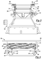
- a food waste disposer 100' (only a top portion of which is shown in Fig. 3 ) having lower mounting flange 218 is mounted to a sink 300 by the engagement of lower mounting flange 218 to a sink flange assembly 302 in accordance with an aspect of the present invention.
- food waste disposer 100' may have the same basic components as food waste disposer 100 of Fig. 1 described above but with some components having a different configuration.
- conveying housing 110' may be a frusto-conical shape such as shown in U.S. 6,007,006 rather than cylindrical.
- a mount other than an anti-vibration mount may be used to attach the inlet housing to the conveying housing.
- Sink flange assembly 302 mates with lower mounting flange 218 described above and thus can be used with food waste disposers having lower mounting flange 218, as discussed in more detail below.
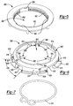
- sink flange assembly 302 includes threaded sink flange 304, sink flange nut 306, upper mounting flange 308 and retainer 310.
- threaded sink flange 304 has a top flange portion 400 that extends radially outwardly from a top of a tubular body portion 402.
- Tubular body portion 402 extends (as oriented in Figs. 3 and 4 ) downwardly from top flange portion 400.
- Tubular body portion 402 has an externally threaded portion 404.
- Tubular body portion 402 also has a plurality of mounting ledges 406 projecting radially outwardly therefrom that each extend horizontally (as oriented in Fig. 4 ) around a portion of an outer circumference of tubular body portion 402.
- Mounting ledges 406 are adjacent and above a lower end 408 of tubular body portion 402.
- Illustratively tubular body portion has three mounting ledges 406 located equidistantly around tubular body portion 402, with gaps 407 therebetween.
- each mounting ledge has a receiving pocket 416 therein.
- each mounting ledge 406 has opposed upwardly projecting extending ends 410, 412 with a generally flat bottom 414 disposed therebetween that cooperate to form receiving pocket 416.
- tubular body portion 402 may have a smooth portion 418 immediately below top flange portion 400 extending for slightly less or slightly more than a thickness of a sink around a sink opening in which sink flange assembly 302 is received.
- Externally threaded portion 404 may extend from smooth portion 418 to slightly above mounting ledges 406 so that a bottom 419 of externally threaded portion 404 is slightly above mounting ledges 406.
- Sink flange assembly 302 may also include sink gasket 206.
- sink flange nut 306 is internally threaded around a central opening 500 with threaded portions 502 interspersed with gaps 504 therebetween.
- Sink flange nut is threadably engageable with the externally threaded portion of tubular body portion 402 of threaded sink flange 304.
- upper mounting flange 308 has an annular shape with a top ring 600 (as oriented in Figs. 3 and 6 ) having a central opening 602 defined by an inner periphery 604 of ring 600.
- a plurality of mounting projections 606 extend radially inwardly from inner periphery 604 with gaps 608 therebetween.
- the mounting projections 606 are illustratively arcuate members having an inner diameter that conforms with an outer diameter of tubular body portion 402 of threaded sink flange 304. In the embodiment shown in Figs.
- upper mounting flange 308 has a mounting projection 606 for each mounting ledge 406 of threaded sink flange 304 so that there are the same number of mounting ledges 406 and mounting projections 606.
- Mounting projections 606 are shaped to be received in receiving pockets 416 of threaded sink flange 304.
- Upper mounting flange 308 has an outer wall 610 that extends downwardly from an outer periphery 612 of top ring 600.
- outer wall 610 is cylindrical.
- a plurality of flanges 614 extend downwardly from a bottom 613 of outer wall 610.
- the flanges 614 are spaced circumferentially from each other equidistantly around outer wall 610 with gaps 616 therebetween and include radially outwardly extending inclined mounting ramps 618 that each have an inclined upper surface 620.
- Mounting ramps 618 are shaped comparably to mounting ramps 222 of upper mounting flange 210 of Fig. 2 .
- Tabs 622 project radially outwardly from bottom 613 of outer wall 610 into gaps 616.
- Each opposed edge 624, 626 of each tab 622 is spaced from an adjacent mounting ramp 618 so that there is a gap 627 between each tab 622 and the mounting ramps 618 on opposite sides of that tab 622.
- Each mounting ramp 618 includes a raised projection 628, such as a radial rib, which latches with a corresponding recess feature (not shown) of lower mounting flange 218 when lower mounting flange 218 has been rotated to a latched position to latch lower mounting flange 218 to upper mounting flange 308. Since a typical lower mounting flange 218 has three mounting tabs 220, an embodiment of upper mounting flange 308 has three mounting ramps 618 for compatibility with lower mounting flange 218. Tabs 622 act as stops that are contacted by curved members 224 of lower mounting flange 218 after lower mounting flange 218 is rotated to the latched position to prevent lower mounting flange 218 from being rotated beyond the latched position.
- retainer 310 is a snap ring.
- Retainer 310 may for example be made of plastic or metal.
- sink flange 304 is placed in a drain opening of a sink with tubular body portion 402 extending downwardly from the drain opening.
- Top flange portion 400 is received in a recess formed in a top surface of the sink around the drain opening with sink gasket 206 disposed therebetween.
- Sink flange nut 306 is tightened on externally threaded portion 404 of tubular body portion 402 until sink flange nut 306 is tightened against a bottom surface of the sink.
- Upper mounting flange 308 is then oriented so that mounting projections 606 are beneath gaps 407 between mounting ledges 406 of tubular body portion 402 of threaded sink flange 304. Upper mounting flange 308 is then lifted up and once mounting projections 606 are above mounting ledges 406, rotated so that mounting projections 606 are directly above receiving pockets 416. Upper mounting flange 308 is then lowered so that mounting projections 606 are received in receiving pockets 416. Retainer 310 is then placed over tubular body portion 402 of threaded sink flange 304 between top ring 600 of upper mounting flange 308 and bottom 419 of externally threaded portion 404 of tubular body portion 402 of threaded sink flange 304.
- Retainer 310 is thus received around the tubular body portion 402 of the threaded sink flange 304 between the bottom 419 of the externally threaded portion 404 of the tubular body portion 402 and top ring 600 of upper mounting flange 308 when upper mounting flange 308 is assembled to the threaded sink flange 304. At least a portion of threads 420 of externally threaded portion 404 project outwardly so that retainer 310 is captured between the threads 420 at the bottom of externally threaded portion 404 and top ring 600 of upper mounting flange 308, preventing upper mounting flange 308 from moving upwardly. Food waste disposer 100' can then be installed by engaging mounting tabs 220 of the lower mounting flange 218 with the mounting ramps 618 of upper mounting flange 308.
- the sink flange assembly 202 shown in Fig. 2 has multiple parts, illustratively six, needed for its attachment to a sink and its use requires multiple steps to attach it to a sink.
- sink flange assembly 302 in accordance with aspects of the present disclosure has fewer parts and is attached to a sink by use of a simple threaded connection.
Landscapes
- Engineering & Computer Science (AREA)
- General Engineering & Computer Science (AREA)
- Environmental & Geological Engineering (AREA)
- Health & Medical Sciences (AREA)
- Life Sciences & Earth Sciences (AREA)
- Hydrology & Water Resources (AREA)
- Public Health (AREA)
- Water Supply & Treatment (AREA)
- Mechanical Engineering (AREA)
- Food Science & Technology (AREA)
- Crushing And Pulverization Processes (AREA)
- Sink And Installation For Waste Water (AREA)
Applications Claiming Priority (2)
| Application Number | Priority Date | Filing Date | Title |
|---|---|---|---|
| US201361835761P | 2013-06-17 | 2013-06-17 | |
| US14/257,281 US9267626B2 (en) | 2013-06-17 | 2014-04-21 | Threaded sink flange assembly for installation of a food waste disposer to a sink |
Publications (2)
| Publication Number | Publication Date |
|---|---|
| EP2816162A1 true EP2816162A1 (de) | 2014-12-24 |
| EP2816162B1 EP2816162B1 (de) | 2018-12-19 |
Family
ID=50943063
Family Applications (1)
| Application Number | Title | Priority Date | Filing Date |
|---|---|---|---|
| EP14170420.5A Active EP2816162B1 (de) | 2013-06-17 | 2014-05-28 | Spülenflanschanordnung mit Gewinde zur Installation eines Lebensmittelabfallentsorgers in einer Spüle |
Country Status (5)
| Country | Link |
|---|---|
| US (1) | US9267626B2 (de) |
| EP (1) | EP2816162B1 (de) |
| CN (1) | CN203924264U (de) |
| AU (1) | AU2014100576A4 (de) |
| ES (1) | ES2708798T3 (de) |
Cited By (4)
| Publication number | Priority date | Publication date | Assignee | Title |
|---|---|---|---|---|
| WO2019191183A1 (en) * | 2018-03-27 | 2019-10-03 | Emerson Electric Co. | Apparatus and method for mounting food waste disposer in relation to sink |
| CN112791771A (zh) * | 2021-01-21 | 2021-05-14 | 周丹 | 一种绿色建筑污水处理系统及污水处理装置 |
| US11639598B2 (en) | 2019-09-30 | 2023-05-02 | InSinkErator LLC | Mounting assemblies and methods for disposer installation |
| WO2025136515A1 (en) * | 2023-12-21 | 2025-06-26 | InSinkErator LLC | Waste disposer system having mounting gasket with chamfer |
Families Citing this family (9)
| Publication number | Priority date | Publication date | Assignee | Title |
|---|---|---|---|---|
| US9506231B2 (en) * | 2013-10-28 | 2016-11-29 | Haier Us Appliance Solutions, Inc. | Waste disposal system with improved mounting assembly |
| CN105040784A (zh) * | 2015-07-23 | 2015-11-11 | 宁波新冠联机电有限公司 | 一种用于食物垃圾处理机的落水口组件 |
| CN107398332B (zh) * | 2017-06-13 | 2023-06-20 | 曹泽鑫 | 排污腔体内具有精细再研磨和增压机构的食物垃圾处理器 |
| CN108937791A (zh) * | 2018-07-31 | 2018-12-07 | 珠海格力电器股份有限公司 | 清洗设备 |
| WO2020160137A1 (en) | 2019-01-29 | 2020-08-06 | Fb Global Plumbing Group Llc | Disposal with above sink installation |
| CN111188957B (zh) * | 2020-01-20 | 2025-09-02 | 青岛海尔智慧厨房电器有限公司 | 一种垃圾处理器的法兰组件及垃圾处理器安装结构 |
| CN116348648A (zh) | 2020-09-30 | 2023-06-27 | 希尔产品公司 | 直接的油脂和/或固体收集系统 |
| CN113006217B (zh) * | 2021-03-11 | 2023-05-12 | 重庆外宇科技有限公司 | 一种餐厨垃圾处理设备 |
| USD1119140S1 (en) * | 2023-12-07 | 2026-03-17 | Emerson Electric Co. | Vacuum cleaner accessory tool |
Citations (7)
| Publication number | Priority date | Publication date | Assignee | Title |
|---|---|---|---|---|
| US2782997A (en) * | 1953-03-18 | 1957-02-26 | Nat Rubber Machinery Co | Garbage disposal apparatus |
| US3025007A (en) | 1960-05-19 | 1962-03-13 | In Sink Erator Mfg Company | Disposal unit |
| US3982703A (en) * | 1974-06-26 | 1976-09-28 | Hobart Corporation | Mounting assembly for food waste disposer |
| US4310933A (en) * | 1979-07-06 | 1982-01-19 | Tappan Company | Food waste disposer mounting assembly |
| GB2162089A (en) * | 1984-07-28 | 1986-01-29 | Daesung Ind Co Ltd | Apparatus for attaching a garbage crusher to a sink |
| US6007006A (en) | 1998-07-23 | 1999-12-28 | Emerson Electric Co. | Food waste disposer |
| US7360729B2 (en) | 2004-04-26 | 2008-04-22 | Emerson Electric Co. | Food waste disposer shredder assembly |
Family Cites Families (23)
| Publication number | Priority date | Publication date | Assignee | Title |
|---|---|---|---|---|
| US2646222A (en) | 1946-03-22 | 1953-07-21 | Martin J Green | Garbage disposal unit |
| US2784915A (en) | 1954-04-22 | 1957-03-12 | Leland S Gordon | Kitchen waste disposal unit |
| US3386671A (en) | 1966-06-13 | 1968-06-04 | Whirlpool Co | Dispser chamber mounting |
| US4405159A (en) | 1981-06-16 | 1983-09-20 | Wastemate Corporation | Waste disposer coupling |
| GB2107979B (en) | 1981-10-29 | 1985-05-01 | Plastic Finishes Ltd | Shower tray waste system |
| US4562602A (en) | 1984-08-27 | 1986-01-07 | Casper Cuschera | Floor drain with waste pipe reduction |
| GB2212576B (en) | 1987-11-14 | 1991-09-04 | Econa Appliances Ltd | Connection assembly |
| JPH10266296A (ja) | 1997-03-21 | 1998-10-06 | Inax Corp | ディスポーザの取付構造 |
| JPH11140935A (ja) | 1997-11-06 | 1999-05-25 | Inax Corp | 流し台設備 |
| JPH11149935A (ja) | 1997-11-18 | 1999-06-02 | Japan Storage Battery Co Ltd | 蓄電池 |
| JPH11157602A (ja) | 1997-11-26 | 1999-06-15 | Yasunaga Corp | 厨芥処理装置 |
| US6360419B1 (en) | 2000-08-14 | 2002-03-26 | Edward Orton Newcomer | Garbage disposal split-ring insertion device |
| JP2003275612A (ja) | 2002-03-19 | 2003-09-30 | Inax Corp | ディスポーザの脱落防止装置 |
| JP2006054803A (ja) | 2004-08-16 | 2006-02-23 | Matsushita Electric Ind Co Ltd | デジタル撮影機器、デジタル撮影機器の画像表示方法、プログラム、および記録媒体 |
| US20060202069A1 (en) | 2005-03-08 | 2006-09-14 | Edward Chavez | Odorless and microbe-resistant food waste disposer |
| JP4876567B2 (ja) | 2005-12-20 | 2012-02-15 | マックス株式会社 | 生ごみ処理装置 |
| US20080290012A1 (en) | 2007-05-24 | 2008-11-27 | Ti-Nien Shih | Water Discharge Pipe and Drain Head Assembly Structure |
| AU2008262356B2 (en) | 2007-06-06 | 2011-12-01 | Emerson Electric Co. | Mount system for a food waste disposer |
| US8220731B2 (en) | 2009-05-20 | 2012-07-17 | Emerson Electric Co. | Food waste disposer and threaded mount system |
| KR101126612B1 (ko) | 2009-09-29 | 2012-03-26 | 주식회사 거성 | 싱크대용 음식물 쓰레기 분쇄장치 |
| US20120080546A1 (en) | 2010-04-19 | 2012-04-05 | Emerson Electric Co. | Food waste disposer and mounting flange therefor with mis-installation prevention features |
| US9139990B2 (en) | 2010-04-19 | 2015-09-22 | Emerson Electric Co. | Food waste disposer and mounting flange therefor with mis-installation prevention features |
| CN202570334U (zh) | 2012-04-16 | 2012-12-05 | 宁波亿盛电机有限公司 | 一种食物垃圾处理器落水口的锁定装置 |
-
2014
- 2014-04-21 US US14/257,281 patent/US9267626B2/en active Active
- 2014-05-28 ES ES14170420T patent/ES2708798T3/es active Active
- 2014-05-28 EP EP14170420.5A patent/EP2816162B1/de active Active
- 2014-05-29 AU AU2014100576A patent/AU2014100576A4/en not_active Expired
- 2014-06-16 CN CN201420321044.XU patent/CN203924264U/zh not_active Expired - Lifetime
Patent Citations (7)
| Publication number | Priority date | Publication date | Assignee | Title |
|---|---|---|---|---|
| US2782997A (en) * | 1953-03-18 | 1957-02-26 | Nat Rubber Machinery Co | Garbage disposal apparatus |
| US3025007A (en) | 1960-05-19 | 1962-03-13 | In Sink Erator Mfg Company | Disposal unit |
| US3982703A (en) * | 1974-06-26 | 1976-09-28 | Hobart Corporation | Mounting assembly for food waste disposer |
| US4310933A (en) * | 1979-07-06 | 1982-01-19 | Tappan Company | Food waste disposer mounting assembly |
| GB2162089A (en) * | 1984-07-28 | 1986-01-29 | Daesung Ind Co Ltd | Apparatus for attaching a garbage crusher to a sink |
| US6007006A (en) | 1998-07-23 | 1999-12-28 | Emerson Electric Co. | Food waste disposer |
| US7360729B2 (en) | 2004-04-26 | 2008-04-22 | Emerson Electric Co. | Food waste disposer shredder assembly |
Cited By (9)
| Publication number | Priority date | Publication date | Assignee | Title |
|---|---|---|---|---|
| WO2019191183A1 (en) * | 2018-03-27 | 2019-10-03 | Emerson Electric Co. | Apparatus and method for mounting food waste disposer in relation to sink |
| CN112218989A (zh) * | 2018-03-27 | 2021-01-12 | 艾默生电气公司 | 相对于水槽固定食物垃圾处理器的设备和方法 |
| US11306467B2 (en) | 2018-03-27 | 2022-04-19 | Emerson Electric Co. | Apparatus and method for mounting food waste disposer in relation to sink |
| CN115075350A (zh) * | 2018-03-27 | 2022-09-20 | 艾默生电气公司 | 固定系统和组装其的方法、食物垃圾处理器系统 |
| EP4223945A1 (de) * | 2018-03-27 | 2023-08-09 | Emerson Electric Co. | Vorrichtung und verfahren zur montage eines lebensmittelabfallentsorgers in bezug auf eine spüle |
| US11639598B2 (en) | 2019-09-30 | 2023-05-02 | InSinkErator LLC | Mounting assemblies and methods for disposer installation |
| US11970849B2 (en) | 2019-09-30 | 2024-04-30 | InSinkErator LLC | Mounting assemblies and methods for disposer installation |
| CN112791771A (zh) * | 2021-01-21 | 2021-05-14 | 周丹 | 一种绿色建筑污水处理系统及污水处理装置 |
| WO2025136515A1 (en) * | 2023-12-21 | 2025-06-26 | InSinkErator LLC | Waste disposer system having mounting gasket with chamfer |
Also Published As
| Publication number | Publication date |
|---|---|
| CN203924264U (zh) | 2014-11-05 |
| US9267626B2 (en) | 2016-02-23 |
| EP2816162B1 (de) | 2018-12-19 |
| AU2014100576A4 (en) | 2014-07-03 |
| ES2708798T3 (es) | 2019-04-11 |
| US20140367963A1 (en) | 2014-12-18 |
Similar Documents
| Publication | Publication Date | Title |
|---|---|---|
| US9267626B2 (en) | Threaded sink flange assembly for installation of a food waste disposer to a sink | |
| US9139990B2 (en) | Food waste disposer and mounting flange therefor with mis-installation prevention features | |
| EP2917420B1 (de) | Schaltanordnung mit stapelweiser zuführung und sperrring zur umrüstung deren auf einem lebensmittelabfallentsorger mit kontinuierlicher zuführung | |
| US8985489B2 (en) | Food waste disposer with food deflecting housing | |
| AU2011101257A4 (en) | Food waste disposer with restricted grind chamber discharge | |
| US6007006A (en) | Food waste disposer | |
| EP2165023B1 (de) | Lebensmittelabfallbeseitiger mit geschirrspülereinlass und herstellungsverfahren dafür | |
| US10626586B2 (en) | Sink and drain for sink | |
| US9574334B2 (en) | Stationary cutter ring for waste disposals | |
| EP1988223B1 (de) | Entsorgungseinheit für Lebensmittelabfälle | |
| US20120193460A1 (en) | Food waste disposer with induced discharge turbulence | |
| AU2011100575A4 (en) | Battery powered food waste disposer | |
| US20160076234A1 (en) | Magnetic baffle ring and magnetic baffle for food waste disposer | |
| EP2130981A2 (de) | Säuberungsmechanismus für Lebensmittelabfallentsorger | |
| US20240416355A1 (en) | Grinding mechanism for food waste disposer | |
| WO2014176155A1 (en) | Food waste disposer with a shredder plate having a plurality of swivel lugs | |
| US20120080546A1 (en) | Food waste disposer and mounting flange therefor with mis-installation prevention features | |
| US3013736A (en) | Domestic appliance | |
| WO2025136515A1 (en) | Waste disposer system having mounting gasket with chamfer | |
| AU2015100460A4 (en) | Magnetically activated switch assembly for food waste disposer | |
| AU2015101664A4 (en) | Food waste disposer with stamped swivel lugs | |
| AU2013101021A4 (en) | Food waste disposer with induced discharge turbulence |
Legal Events
| Date | Code | Title | Description |
|---|---|---|---|
| PUAI | Public reference made under article 153(3) epc to a published international application that has entered the european phase |
Free format text: ORIGINAL CODE: 0009012 |
|
| 17P | Request for examination filed |
Effective date: 20140528 |
|
| AK | Designated contracting states |
Kind code of ref document: A1 Designated state(s): AL AT BE BG CH CY CZ DE DK EE ES FI FR GB GR HR HU IE IS IT LI LT LU LV MC MK MT NL NO PL PT RO RS SE SI SK SM TR |
|
| AX | Request for extension of the european patent |
Extension state: BA ME |
|
| R17P | Request for examination filed (corrected) |
Effective date: 20150619 |
|
| RBV | Designated contracting states (corrected) |
Designated state(s): AL AT BE BG CH CY CZ DE DK EE ES FI FR GB GR HR HU IE IS IT LI LT LU LV MC MK MT NL NO PL PT RO RS SE SI SK SM TR |
|
| GRAP | Despatch of communication of intention to grant a patent |
Free format text: ORIGINAL CODE: EPIDOSNIGR1 |
|
| STAA | Information on the status of an ep patent application or granted ep patent |
Free format text: STATUS: GRANT OF PATENT IS INTENDED |
|
| INTG | Intention to grant announced |
Effective date: 20180710 |
|
| GRAS | Grant fee paid |
Free format text: ORIGINAL CODE: EPIDOSNIGR3 |
|
| GRAA | (expected) grant |
Free format text: ORIGINAL CODE: 0009210 |
|
| STAA | Information on the status of an ep patent application or granted ep patent |
Free format text: STATUS: THE PATENT HAS BEEN GRANTED |
|
| AK | Designated contracting states |
Kind code of ref document: B1 Designated state(s): AL AT BE BG CH CY CZ DE DK EE ES FI FR GB GR HR HU IE IS IT LI LT LU LV MC MK MT NL NO PL PT RO RS SE SI SK SM TR |
|
| REG | Reference to a national code |
Ref country code: GB Ref legal event code: FG4D |
|
| REG | Reference to a national code |
Ref country code: CH Ref legal event code: EP |
|
| REG | Reference to a national code |
Ref country code: DE Ref legal event code: R096 Ref document number: 602014038097 Country of ref document: DE |
|
| REG | Reference to a national code |
Ref country code: IE Ref legal event code: FG4D |
|
| REG | Reference to a national code |
Ref country code: AT Ref legal event code: REF Ref document number: 1078867 Country of ref document: AT Kind code of ref document: T Effective date: 20190115 |
|
| REG | Reference to a national code |
Ref country code: SE Ref legal event code: TRGR |
|
| REG | Reference to a national code |
Ref country code: ES Ref legal event code: FG2A Ref document number: 2708798 Country of ref document: ES Kind code of ref document: T3 Effective date: 20190411 |
|
| REG | Reference to a national code |
Ref country code: NL Ref legal event code: MP Effective date: 20181219 |
|
| PG25 | Lapsed in a contracting state [announced via postgrant information from national office to epo] |
Ref country code: NO Free format text: LAPSE BECAUSE OF FAILURE TO SUBMIT A TRANSLATION OF THE DESCRIPTION OR TO PAY THE FEE WITHIN THE PRESCRIBED TIME-LIMIT Effective date: 20190319 Ref country code: LT Free format text: LAPSE BECAUSE OF FAILURE TO SUBMIT A TRANSLATION OF THE DESCRIPTION OR TO PAY THE FEE WITHIN THE PRESCRIBED TIME-LIMIT Effective date: 20181219 Ref country code: FI Free format text: LAPSE BECAUSE OF FAILURE TO SUBMIT A TRANSLATION OF THE DESCRIPTION OR TO PAY THE FEE WITHIN THE PRESCRIBED TIME-LIMIT Effective date: 20181219 Ref country code: LV Free format text: LAPSE BECAUSE OF FAILURE TO SUBMIT A TRANSLATION OF THE DESCRIPTION OR TO PAY THE FEE WITHIN THE PRESCRIBED TIME-LIMIT Effective date: 20181219 Ref country code: HR Free format text: LAPSE BECAUSE OF FAILURE TO SUBMIT A TRANSLATION OF THE DESCRIPTION OR TO PAY THE FEE WITHIN THE PRESCRIBED TIME-LIMIT Effective date: 20181219 Ref country code: BG Free format text: LAPSE BECAUSE OF FAILURE TO SUBMIT A TRANSLATION OF THE DESCRIPTION OR TO PAY THE FEE WITHIN THE PRESCRIBED TIME-LIMIT Effective date: 20190319 |
|
| REG | Reference to a national code |
Ref country code: LT Ref legal event code: MG4D |
|
| REG | Reference to a national code |
Ref country code: AT Ref legal event code: MK05 Ref document number: 1078867 Country of ref document: AT Kind code of ref document: T Effective date: 20181219 |
|
| PG25 | Lapsed in a contracting state [announced via postgrant information from national office to epo] |
Ref country code: GR Free format text: LAPSE BECAUSE OF FAILURE TO SUBMIT A TRANSLATION OF THE DESCRIPTION OR TO PAY THE FEE WITHIN THE PRESCRIBED TIME-LIMIT Effective date: 20190320 Ref country code: AL Free format text: LAPSE BECAUSE OF FAILURE TO SUBMIT A TRANSLATION OF THE DESCRIPTION OR TO PAY THE FEE WITHIN THE PRESCRIBED TIME-LIMIT Effective date: 20181219 Ref country code: RS Free format text: LAPSE BECAUSE OF FAILURE TO SUBMIT A TRANSLATION OF THE DESCRIPTION OR TO PAY THE FEE WITHIN THE PRESCRIBED TIME-LIMIT Effective date: 20181219 |
|
| PG25 | Lapsed in a contracting state [announced via postgrant information from national office to epo] |
Ref country code: NL Free format text: LAPSE BECAUSE OF FAILURE TO SUBMIT A TRANSLATION OF THE DESCRIPTION OR TO PAY THE FEE WITHIN THE PRESCRIBED TIME-LIMIT Effective date: 20181219 |
|
| PG25 | Lapsed in a contracting state [announced via postgrant information from national office to epo] |
Ref country code: PL Free format text: LAPSE BECAUSE OF FAILURE TO SUBMIT A TRANSLATION OF THE DESCRIPTION OR TO PAY THE FEE WITHIN THE PRESCRIBED TIME-LIMIT Effective date: 20181219 Ref country code: CZ Free format text: LAPSE BECAUSE OF FAILURE TO SUBMIT A TRANSLATION OF THE DESCRIPTION OR TO PAY THE FEE WITHIN THE PRESCRIBED TIME-LIMIT Effective date: 20181219 Ref country code: PT Free format text: LAPSE BECAUSE OF FAILURE TO SUBMIT A TRANSLATION OF THE DESCRIPTION OR TO PAY THE FEE WITHIN THE PRESCRIBED TIME-LIMIT Effective date: 20190419 |
|
| PG25 | Lapsed in a contracting state [announced via postgrant information from national office to epo] |
Ref country code: EE Free format text: LAPSE BECAUSE OF FAILURE TO SUBMIT A TRANSLATION OF THE DESCRIPTION OR TO PAY THE FEE WITHIN THE PRESCRIBED TIME-LIMIT Effective date: 20181219 Ref country code: SM Free format text: LAPSE BECAUSE OF FAILURE TO SUBMIT A TRANSLATION OF THE DESCRIPTION OR TO PAY THE FEE WITHIN THE PRESCRIBED TIME-LIMIT Effective date: 20181219 Ref country code: SK Free format text: LAPSE BECAUSE OF FAILURE TO SUBMIT A TRANSLATION OF THE DESCRIPTION OR TO PAY THE FEE WITHIN THE PRESCRIBED TIME-LIMIT Effective date: 20181219 Ref country code: IS Free format text: LAPSE BECAUSE OF FAILURE TO SUBMIT A TRANSLATION OF THE DESCRIPTION OR TO PAY THE FEE WITHIN THE PRESCRIBED TIME-LIMIT Effective date: 20190419 Ref country code: RO Free format text: LAPSE BECAUSE OF FAILURE TO SUBMIT A TRANSLATION OF THE DESCRIPTION OR TO PAY THE FEE WITHIN THE PRESCRIBED TIME-LIMIT Effective date: 20181219 |
|
| PGFP | Annual fee paid to national office [announced via postgrant information from national office to epo] |
Ref country code: SE Payment date: 20190531 Year of fee payment: 6 |
|
| REG | Reference to a national code |
Ref country code: DE Ref legal event code: R097 Ref document number: 602014038097 Country of ref document: DE |
|
| PLBE | No opposition filed within time limit |
Free format text: ORIGINAL CODE: 0009261 |
|
| STAA | Information on the status of an ep patent application or granted ep patent |
Free format text: STATUS: NO OPPOSITION FILED WITHIN TIME LIMIT |
|
| PG25 | Lapsed in a contracting state [announced via postgrant information from national office to epo] |
Ref country code: AT Free format text: LAPSE BECAUSE OF FAILURE TO SUBMIT A TRANSLATION OF THE DESCRIPTION OR TO PAY THE FEE WITHIN THE PRESCRIBED TIME-LIMIT Effective date: 20181219 Ref country code: DK Free format text: LAPSE BECAUSE OF FAILURE TO SUBMIT A TRANSLATION OF THE DESCRIPTION OR TO PAY THE FEE WITHIN THE PRESCRIBED TIME-LIMIT Effective date: 20181219 |
|
| 26N | No opposition filed |
Effective date: 20190920 |
|
| REG | Reference to a national code |
Ref country code: DE Ref legal event code: R119 Ref document number: 602014038097 Country of ref document: DE |
|
| REG | Reference to a national code |
Ref country code: CH Ref legal event code: PL |
|
| PG25 | Lapsed in a contracting state [announced via postgrant information from national office to epo] |
Ref country code: MC Free format text: LAPSE BECAUSE OF FAILURE TO SUBMIT A TRANSLATION OF THE DESCRIPTION OR TO PAY THE FEE WITHIN THE PRESCRIBED TIME-LIMIT Effective date: 20181219 Ref country code: LI Free format text: LAPSE BECAUSE OF NON-PAYMENT OF DUE FEES Effective date: 20190531 Ref country code: CH Free format text: LAPSE BECAUSE OF NON-PAYMENT OF DUE FEES Effective date: 20190531 |
|
| REG | Reference to a national code |
Ref country code: BE Ref legal event code: MM Effective date: 20190531 |
|
| PG25 | Lapsed in a contracting state [announced via postgrant information from national office to epo] |
Ref country code: LU Free format text: LAPSE BECAUSE OF NON-PAYMENT OF DUE FEES Effective date: 20190528 Ref country code: SI Free format text: LAPSE BECAUSE OF FAILURE TO SUBMIT A TRANSLATION OF THE DESCRIPTION OR TO PAY THE FEE WITHIN THE PRESCRIBED TIME-LIMIT Effective date: 20181219 |
|
| PG25 | Lapsed in a contracting state [announced via postgrant information from national office to epo] |
Ref country code: TR Free format text: LAPSE BECAUSE OF FAILURE TO SUBMIT A TRANSLATION OF THE DESCRIPTION OR TO PAY THE FEE WITHIN THE PRESCRIBED TIME-LIMIT Effective date: 20181219 |
|
| PG25 | Lapsed in a contracting state [announced via postgrant information from national office to epo] |
Ref country code: IE Free format text: LAPSE BECAUSE OF NON-PAYMENT OF DUE FEES Effective date: 20190528 Ref country code: DE Free format text: LAPSE BECAUSE OF NON-PAYMENT OF DUE FEES Effective date: 20191203 |
|
| PG25 | Lapsed in a contracting state [announced via postgrant information from national office to epo] |
Ref country code: BE Free format text: LAPSE BECAUSE OF NON-PAYMENT OF DUE FEES Effective date: 20190531 |
|
| PG25 | Lapsed in a contracting state [announced via postgrant information from national office to epo] |
Ref country code: FR Free format text: LAPSE BECAUSE OF NON-PAYMENT OF DUE FEES Effective date: 20190531 |
|
| PG25 | Lapsed in a contracting state [announced via postgrant information from national office to epo] |
Ref country code: SE Free format text: LAPSE BECAUSE OF NON-PAYMENT OF DUE FEES Effective date: 20200529 |
|
| PG25 | Lapsed in a contracting state [announced via postgrant information from national office to epo] |
Ref country code: CY Free format text: LAPSE BECAUSE OF FAILURE TO SUBMIT A TRANSLATION OF THE DESCRIPTION OR TO PAY THE FEE WITHIN THE PRESCRIBED TIME-LIMIT Effective date: 20181219 |
|
| PG25 | Lapsed in a contracting state [announced via postgrant information from national office to epo] |
Ref country code: MT Free format text: LAPSE BECAUSE OF FAILURE TO SUBMIT A TRANSLATION OF THE DESCRIPTION OR TO PAY THE FEE WITHIN THE PRESCRIBED TIME-LIMIT Effective date: 20181219 Ref country code: HU Free format text: LAPSE BECAUSE OF FAILURE TO SUBMIT A TRANSLATION OF THE DESCRIPTION OR TO PAY THE FEE WITHIN THE PRESCRIBED TIME-LIMIT; INVALID AB INITIO Effective date: 20140528 |
|
| PG25 | Lapsed in a contracting state [announced via postgrant information from national office to epo] |
Ref country code: MK Free format text: LAPSE BECAUSE OF FAILURE TO SUBMIT A TRANSLATION OF THE DESCRIPTION OR TO PAY THE FEE WITHIN THE PRESCRIBED TIME-LIMIT Effective date: 20181219 |
|
| P01 | Opt-out of the competence of the unified patent court (upc) registered |
Effective date: 20230523 |
|
| PGFP | Annual fee paid to national office [announced via postgrant information from national office to epo] |
Ref country code: ES Payment date: 20250612 Year of fee payment: 12 Ref country code: GB Payment date: 20250520 Year of fee payment: 12 |
|
| PGFP | Annual fee paid to national office [announced via postgrant information from national office to epo] |
Ref country code: IT Payment date: 20250522 Year of fee payment: 12 |