EP2815451B1 - Verfahren zum überwachen einer batterie - Google Patents
Verfahren zum überwachen einer batterie Download PDFInfo
- Publication number
- EP2815451B1 EP2815451B1 EP13700654.0A EP13700654A EP2815451B1 EP 2815451 B1 EP2815451 B1 EP 2815451B1 EP 13700654 A EP13700654 A EP 13700654A EP 2815451 B1 EP2815451 B1 EP 2815451B1
- Authority
- EP
- European Patent Office
- Prior art keywords
- data
- sensors
- sensor
- battery
- controller
- Prior art date
- Legal status (The legal status is an assumption and is not a legal conclusion. Google has not performed a legal analysis and makes no representation as to the accuracy of the status listed.)
- Active
Links
Images

Classifications
-
- H—ELECTRICITY
- H01—ELECTRIC ELEMENTS
- H01M—PROCESSES OR MEANS, e.g. BATTERIES, FOR THE DIRECT CONVERSION OF CHEMICAL ENERGY INTO ELECTRICAL ENERGY
- H01M10/00—Secondary cells; Manufacture thereof
- H01M10/42—Methods or arrangements for servicing or maintenance of secondary cells or secondary half-cells
- H01M10/425—Structural combination with electronic components, e.g. electronic circuits integrated to the outside of the casing
- H01M10/4257—Smart batteries, e.g. electronic circuits inside the housing of the cells or batteries
-
- G—PHYSICS
- G01—MEASURING; TESTING
- G01R—MEASURING ELECTRIC VARIABLES; MEASURING MAGNETIC VARIABLES
- G01R31/00—Arrangements for testing electric properties; Arrangements for locating electric faults; Arrangements for electrical testing characterised by what is being tested not provided for elsewhere
- G01R31/36—Arrangements for testing, measuring or monitoring the electrical condition of accumulators or electric batteries, e.g. capacity or state of charge [SoC]
- G01R31/3644—Constructional arrangements
- G01R31/3648—Constructional arrangements comprising digital calculation means, e.g. for performing an algorithm
-
- H—ELECTRICITY
- H01—ELECTRIC ELEMENTS
- H01M—PROCESSES OR MEANS, e.g. BATTERIES, FOR THE DIRECT CONVERSION OF CHEMICAL ENERGY INTO ELECTRICAL ENERGY
- H01M10/00—Secondary cells; Manufacture thereof
- H01M10/42—Methods or arrangements for servicing or maintenance of secondary cells or secondary half-cells
- H01M10/425—Structural combination with electronic components, e.g. electronic circuits integrated to the outside of the casing
-
- H—ELECTRICITY
- H01—ELECTRIC ELEMENTS
- H01M—PROCESSES OR MEANS, e.g. BATTERIES, FOR THE DIRECT CONVERSION OF CHEMICAL ENERGY INTO ELECTRICAL ENERGY
- H01M10/00—Secondary cells; Manufacture thereof
- H01M10/42—Methods or arrangements for servicing or maintenance of secondary cells or secondary half-cells
- H01M10/48—Accumulators combined with arrangements for measuring, testing or indicating the condition of cells, e.g. the level or density of the electrolyte
- H01M10/482—Accumulators combined with arrangements for measuring, testing or indicating the condition of cells, e.g. the level or density of the electrolyte for several batteries or cells simultaneously or sequentially
-
- H—ELECTRICITY
- H04—ELECTRIC COMMUNICATION TECHNIQUE
- H04Q—SELECTING
- H04Q9/00—Arrangements in telecontrol or telemetry systems for selectively calling a substation from a main station, in which substation desired apparatus is selected for applying a control signal thereto or for obtaining measured values therefrom
-
- H—ELECTRICITY
- H01—ELECTRIC ELEMENTS
- H01M—PROCESSES OR MEANS, e.g. BATTERIES, FOR THE DIRECT CONVERSION OF CHEMICAL ENERGY INTO ELECTRICAL ENERGY
- H01M10/00—Secondary cells; Manufacture thereof
- H01M10/42—Methods or arrangements for servicing or maintenance of secondary cells or secondary half-cells
- H01M10/425—Structural combination with electronic components, e.g. electronic circuits integrated to the outside of the casing
- H01M2010/4278—Systems for data transfer from batteries, e.g. transfer of battery parameters to a controller, data transferred between battery controller and main controller
-
- H—ELECTRICITY
- H04—ELECTRIC COMMUNICATION TECHNIQUE
- H04Q—SELECTING
- H04Q2209/00—Arrangements in telecontrol or telemetry systems
- H04Q2209/10—Arrangements in telecontrol or telemetry systems using a centralized architecture
-
- H—ELECTRICITY
- H04—ELECTRIC COMMUNICATION TECHNIQUE
- H04Q—SELECTING
- H04Q2209/00—Arrangements in telecontrol or telemetry systems
- H04Q2209/30—Arrangements in telecontrol or telemetry systems using a wired architecture
-
- H—ELECTRICITY
- H04—ELECTRIC COMMUNICATION TECHNIQUE
- H04Q—SELECTING
- H04Q2209/00—Arrangements in telecontrol or telemetry systems
- H04Q2209/80—Arrangements in the sub-station, i.e. sensing device
- H04Q2209/82—Arrangements in the sub-station, i.e. sensing device where the sensing device takes the initiative of sending data
-
- Y—GENERAL TAGGING OF NEW TECHNOLOGICAL DEVELOPMENTS; GENERAL TAGGING OF CROSS-SECTIONAL TECHNOLOGIES SPANNING OVER SEVERAL SECTIONS OF THE IPC; TECHNICAL SUBJECTS COVERED BY FORMER USPC CROSS-REFERENCE ART COLLECTIONS [XRACs] AND DIGESTS
- Y02—TECHNOLOGIES OR APPLICATIONS FOR MITIGATION OR ADAPTATION AGAINST CLIMATE CHANGE
- Y02E—REDUCTION OF GREENHOUSE GAS [GHG] EMISSIONS, RELATED TO ENERGY GENERATION, TRANSMISSION OR DISTRIBUTION
- Y02E60/00—Enabling technologies; Technologies with a potential or indirect contribution to GHG emissions mitigation
- Y02E60/10—Energy storage using batteries
Definitions
- the invention relates to a method for monitoring a battery, a battery which is designed for carrying out the method, and an arrangement which is used in such a battery for carrying out the presented method.
- a battery is an interconnection of a plurality of generally similar galvanic cells and is an electrochemical energy storage and an energy converter, which is provided for the delivery of electrical energy. For this purpose, stored in the battery during discharge chemical energy is converted by the electrochemical reaction into electrical energy.
- the cells of the battery which may be connected in parallel or in series or mixed, arranged in so-called modules. One or more of these modules, connected in series or in parallel, form the battery.
- a rechargeable battery is also referred to as a rechargeable battery with rechargeable batteries.
- battery is understood to mean both a non-rechargeable and a rechargeable battery.
- Batteries are used, for example, in motor vehicles for providing the electric current for the starter of the internal combustion engine used.
- a battery is referred to as a starter battery and is, for example, designed as a lead-acid battery.
- the battery In addition to supplying the starter, the battery also supplies the other electrical consumers in the vehicle. To start the internal combustion engine For a short time, high currents are required, which must be provided even at low temperatures.
- batteries are also used as energy sources for driving the vehicle. These are also referred to as traction batteries.
- characteristic quantities or operating variables of the battery such as, for example, terminal voltage, temperature, pressure, in particular internal cell pressure, current, impedance, etc., are recorded.
- sensors in the battery for monitoring and communication. Furthermore, it is known to detect sensor signals within the battery via dedicated data lines, for example the CAN bus, which is typically used in motor vehicles.
- a battery with battery cells and a method for monitoring the battery are described.
- the presented battery has a plurality of battery cell stacks, wherein a battery cell stack has a single battery cell or can be constructed of parallel-connected battery cells.
- Sensors monitor the state of charge of individual battery cells.
- the described battery is associated with a charge balancing device having a target value table of the allowable state of charge of individual batteries. Depending on the state of charge, the charge compensation device varies with the state of charge.
- the charge balance of the battery cells is interrupted.
- a tap of a charge equalization line is arranged, wherein the charge balancing arrangements are combined in a wire harness and provided cell monitoring modules, which in turn sensors and cell monitoring circuits, said components of the cell monitoring are arranged together in the charge balancing device spatially separated from the battery cells.
- a method of monitoring a battery associated with a number of sensors is known.
- the sensors are connected in series via a data line and to a control unit.
- At least one of the sensors measures in each case at least one variable which relates to a functional state of the battery, and outputs the measurement data thereby obtained to the data line for transmission to the control unit.
- a similar process is in each case also from the document US 2009/0265121 A1 and from the publication US 202/0163339 A1 known.
- the from the publication US 202/0163339 A1 known control unit is further adapted to the at least one sensor to control such that it measures at predefined times the at least one size.
- a communication between battery sensors to battery cells and to a central control unit can be performed.
- each sensor transmits in design its data or a data word to the next, this adds its data and passes the entire package to the next sensor on.
- the control unit is connected at the end of the chain and receives a complete data package with the data of all sensors. Thus, each sensor outputs a data word associated with it on the data line. All data words together form the total data package.
- a return channel from the controller to the first sensor in the chain is provided. Then, the data and / or control signals also travel through the chain until they are received by all the sensors.
- the sensors may be outside or inside the cell. In the latter case, a bushing for two additional wires is necessary. If a return channel is provided, the data words or the total data package can "run in a circle" and can also be overwritten by the respective sensors again.
- At least one of the sensors in each case gives at least one data word to the data line.
- the data words can be joined together to form a total data packet and the total data packet can be sent via the data line to the control unit.
- a first data word is sent from one sensor to a next sensor via the data line, another data word is added to the first data word by the next sensor, and this is done until a total data packet containing data words of all the sensors is added the control unit arrives.
- a first data word is sent from a sensor to the data line and this is transmitted to the control unit and after a predetermined period of time a next sensor receives a second data word on the data line there.
- the first sensor may, for example, be a "normal" RS232 data packet with e.g. Send 8 bits of content and then provide a break, for example 200 * the time required for transmission to the controller. The next or second sensor then hangs its data word behind it, etc. Then the controller receives e.g. One hundred 8-bit data packets that can be received in succession with a standard RS232 receiver (UART).
- the method described can be used for all applications in which parameters, such as, for example, the temperature, have to be measured during operation.
- the method is particularly suitable for use in batteries in motor vehicles, in particular in electric vehicles.
- the cell voltage can also be measured. The evaluation can then take place in the connected control unit.
- Another possible function that can be supported is cell balancing.
- the sensors that receive the measurements may be in contact with associated battery modules or cells, i. the sensors are arranged on or in the modules or cells.
- each module or each cell can be assigned a sensor.
- the sensors can then give at least one measured variable and / or information, for example "OK” and "non-OK", to the state of the assigned module or the associated cell.
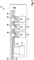
- FIG. 1 an embodiment of the presented battery, indicated generally by the reference numeral 10, reproduced.
- the illustration shows a control unit 12, a first cell 14, a second cell 16 and a third cell 18.
- the illustration only three cells 14, 16 and 18 are shown for the sake of clarity, it is of course also possible to have more cells 14, 16, 18 be provided, which in turn may be grouped into modules.
- the individual cells may in turn comprise a number of galvanic cells.
- the first cell 14 is a first sensor 20, the second cell 16, a second sensor 22 and the third cell 18, a third sensor 24 assigned.
- each cell 14, 16 and 18 is associated with exactly one sensor 20, 22 and 24, respectively.
- sensors 20, 22, 24 are assigned to only some of the cells 14, 16, 18, galvanic cells, modules and also only some of the modules.
- the cells 14, 16, 18 are connected in series in this embodiment and may in turn comprise a parallel and / or series connection of galvanic cells.
- the illustration shows two bus bars 30 and 32, via which the cells 14, 16 and 18 are connected and via which the sensors 20, 22 and 24 can also be supplied.
- the sensors 20, 22, 24 can also each be supplied from the associated cell 14, 16, 18 or by a dedicated supply line.
- a serial data line 40 is shown, via which the sensors 20, 22 and 24 are connected in series or in series. At one end of the serial connection, the controller 12 is connected.
- the Sensors 20, 22 and 24 are connected to the serial data line 40 via serial sensor interfaces 36.
- the illustration also shows an optional return channel 42 and a connection 44 to the next cell, not shown in this illustration.
- the serial data line 40, the sensor interfaces 36, the sensors 20, 22, and 24, and the controller 12 represent an assembly 50 that enables serial communication between individual cells 14, 16, and 18.
- each sensor 20, 22 and 24 can transmit a data word to the next sensor 20, 22 and 24. This then adds its data word to the transmitted data packet and passes this on to the next sensor 20, 22 and 24 on.
- the control unit 12 at the end of the chain receives information about all sensors 20, 22 and 24 or cells 14, 16 and 18.
- the intended return channel 42 from the controller 12 to the first sensor 20 and from this further serves to data, eg. Control signals or configuration files to send to the sensors 20, 22 and 24.
- FIG. 2 is a flowchart, a possible embodiment of the method presented that basically allows communication between sensors in a battery or between parts, such as cells or modules, the battery and therefore can be used to monitor this battery.
- a first sensor outputs a measured value, which was acquired by an assigned cell and provides information about the operating state and, if appropriate, the functionality of this cell, via a serial sensor interface to a serial data line.
- This measured value or a data word representing it is sent to a further, serially arranged sensor via the serial data line in a further step 72, which in turn attaches a corresponding data word to the received data packet in a further step 74.
Description
- Die Erfindung betrifft ein Verfahren zum Überwachen einer Batterie, eine Batterie, die zur Durchführung des Verfahrens ausgebildet ist, und eine Anordnung, die in einer solchen Batterie zur Durchführung des vorgestellten Verfahrens zur Anwendung kommt.
- Eine Batterie ist eine Zusammenschaltung mehrerer in der Regel gleichartiger galvanischer Zellen und stellt einen elektrochemischen Energiespeicher und einen Energiewandler dar, der zur Abgabe elektrischer Energie vorgesehen ist. Hierzu wird in der Batterie bei der Entladung gespeicherte chemische Energie durch die elektrochemische Reaktion in elektrische Energie umgewandelt. Dabei sind die Zellen der Batterie, die parallel oder in Reihe oder gemischt geschaltet sein können, in sogenannten Modulen angeordnet. Eines oder mehrere dieser Module, in Reihe oder parallel geschaltet, bilden die Batterie.
- Bei den genannten Zellen wird zwischen Primärzellen, die nicht wiederaufladbar sind, und Sekundärzellen, die wiederaufladbar sind, unterschieden. Eine wiederaufladbaren Batterie wird auch als Akkumulator mit Akkuzellen bezeichnet. Im folgenden wird unter Batterie sowohl eine nicht wiederaufladbare als auch eine wiederaufladbare Batterie verstanden.
- Batterien kommen bspw. in Kraftfahrzeugen zur Bereitstellung des elektrischen Stroms für den Anlasser des Verbrennungsmotors zum Einsatz. Eine solche Batterie wird als Starterbatterie bezeichnet und ist bspw. als Bleiakkumulator ausgebildet. Neben der Versorgung des Anlassers versorgt die Batterie auch die anderen elektrischen Verbraucher im Fahrzeug. Zum Anlassen des Verbrennungsmotors sind kurzzeitig hohe Ströme erforderlich, die auch bei niedrigen Temperaturen bereitgestellt werden müssen.
- In Elektrofahrzeugen oder Hybridfahrzeugen werden Batterien auch als Energiequellen für den Antrieb des Fahrzeugs verwendet. Diese werden auch als Traktionsbatterien bezeichnet.
- In jedem Fall ist es erforderlich, die Funktionsfähigkeit der Batterie im Fahrzeug regelmäßig oder gar kontinuierlich zu überwachen, um einen sicheren Betrieb des Kraftfahrzeugs zu gewährleisten. Hierzu werden Kenn- bzw. Betriebsgrößen der Batterie, wie bspw. Klemmenspannung, Temperatur, Druck, insbesondere Zellinnendruck, Strom, Impedanz usw., aufgenommen.
- Es ist bekannt, zur Überwachung und Kommunikation Sensoren in der Batterie einzusetzen. Weiterhin ist es bekannt, innerhalb der Batterie Sensorsignale über dafür vorgesehene Datenleitungen, bspw. den CAN-Bus, der typischerweise in Kraftfahrzeugen eingesetzt wird, zu erfassen.
- In der Druckschrift
WO 2009/149690 A1 sind eine Batterie mit Batteriezellen und ein Verfahren zum Überwachen der Batterie beschrieben. Die vorgestellte Batterie weist eine Vielzahl von Batteriezellenstapeln auf, wobei ein Batteriezellenstapel eine einzige Batteriezelle aufweist oder aus parallel geschalteten Batteriezellen aufgebaut sein kann. Sensoren überwachen den Ladezustand einzelner Batteriezellen. Der beschriebenen Batterie ist eine Ladungsausgleichseinrichtung zugeordnet, die eine Zielwerttabelle des zulässigen Ladezustands einzelner Batterien aufweist. In Abhängigkeit des Ladezustands variiert die Ladungsausgleichseinrichtung mit dem Ladezustand. - Bei Erreichen des Zielwerts für den Ladezustand einzelner Batteriezellen wird der Ladungsausgleich der Batteriezellen unterbrochen. An jeder Batteriezelle ist ein Abgriff einer Ladungsausgleichsleitung angeordnet, wobei die Ladungsausgleichsanordnungen in einem Kabelbaum vereinigt sind und vorgesehenen Zellenüberwachungsmodulen zugeführt werden, die ihrerseits Sensoren und Zellüberwachungsschaltkreise aufweisen, wobei diese Komponenten der Zellüberwachung gemeinsam in der Ladungsausgleichseinrichtung räumlich von den Batteriezellen getrennt, angeordnet sind.
- Aus der Druckschrift
US 2011/0068746 A1 ist ein Verfahren zum Überwachen einer Batterie, der eine Anzahl von Sensoren zugeordnet ist, bekannt. Dabei sind die Sensoren über eine Datenleitung seriell miteinander und mit einem Steuergerät verbunden. Mindestens einer der Sensoren misst jeweils mindestens eine Größe, die einen Funktionszustand der Batterie betrifft, und gibt die dabei gewonnenen Messdaten auf die Datenleitung zur Übermittlung an das Steuergerät. Ein ähnliches Verfahren ist jeweils auch aus der DruckschriftUS 2009/0265121 A1 und aus der DruckschriftUS 202/0163339 A1 bekannt. Die aus der DruckschriftUS 202/0163339 A1 bekannte Steuereinheit ist ferner dazu ausgebildet, den mindestens einen Sensor derartig anzusteuern, dass dieser zu vordefinierten Zeitpunkten die mindestens eine Größe misst. - Vor diesem Hintergrund werden ein Verfahren zum Überwachen einer Batterie nach Anspruch 1 und eine entsprechende Anordnung zum Überwachen einer Batterie gemäß Anspruch 8 vorgestellt. Ausgestaltungen ergeben sich aus den abhängigen Ansprüchen und der Beschreibung.
- Mit dem vorgestellten Verfahren kann eine Kommunikation zwischen Batteriesensoren an Batteriezellen und zu einem zentralen Steuergerät durchgeführt werden.
- Bislang ist die Anbringung oder Einbringung von Batteriesensoren in einem Sensorsystem an oder in Batteriezellen von Hybrid- und Elektrofahrzeugen bekannt. Typischerweise sind das 100 oder mehr Zellen, von denen jede mit einem Batteriesensor versehen sein kann. Zwischen diesen Sensoren und einem zentralen Steuergerät müssen Messdaten und Steuerbefehle uni- oder bidirektional ausgetauscht werden.
- Es wird nunmehr die Verwendung einer seriellen Kommunikation zwischen den einzelnen Sensoren beschrieben. Jeder Sensor übermittelt in Ausgestaltung seine Daten bzw. ein Datenwort an den nächsten, dieser fügt seine Daten hinzu und reicht das Gesamtpaket an den nächsten Sensor weiter. Das Steuergerät ist am Ende der Kette angeschlossen und erhält ein Datengesamtpaket mit den Daten aller Sensoren. Somit gibt jeder Sensor ein ihm zugeordnetes Datenwort auf die Datenleitung. Alle Datenwörter bilden aneinandergefügt das Datengesamtpaket. In der anderen Richtung ist ein Rückkanal vom Steuergerät zum ersten Sensor in der Kette vorgesehen. Dann wandern die Daten und/oder Steuersignale ebenfalls die Kette durch, bis sie von allen Sensoren empfangen wurden. Die Sensoren können sich außerhalb oder innerhalb der Zelle befinden. Im letzteren Fall ist eine Durchführung für zwei zusätzliche Drähte notwendig. Ist ein Rückkanal vorgesehen, können die Datenwörter bzw. das Datengesamtpaket "im Kreis laufen" und auch wieder von den jeweiligen Sensoren überschrieben werden.
- Bei dem vorgestellten Verfahren ist vorgesehen, dass mindestens einer der Sensoren jeweils wenigstens ein Datenwort auf die Datenleitung gibt. Dabei können die Datenwörter zu einem Datengesamtpaket aneinandergefügt werden und das Datengesamtpaket über die Datenleitung zu dem Steuergerät gesendet werden.
- In einer Ausführung wird ein erstes Datenwort von einem Sensor über die Datenleitung zu einem nächsten Sensor gesendet wird, von dem nächsten Sensor ein weiteres Datenwort an das erste Datenwort angefügt wird und dies solange durchgeführt wird, bis ein Datengesamtpaket, das Datenwörter sämtlicher Sensoren enthält, zu dem Steuergerät gelangt.
- Sollte vorab bekannt sein, wie groß das vom Steuergerät zu empfangene Datenpaket ist, kann alternativ vorgesehen sein, dass ein erstes Datenwort von einem Sensor auf die Datenleitung gegeben wird und dieses zu dem Steuergerät übermittelt wird und nach einem vorbestimmten Zeitraum ein nächster Sensor ein zweites Datenwort auf die Datenleitung gibt. In diesem Fall kann der erste Sensor bspw. ein "normales" RS232-Datenpaket mit z.B. 8 Bit Inhalt senden und dann eine Pause vorsehen, bspw. 200 * der Zeitraum, der für die Übermittlung zum Steuergerät erforderlich ist. Der nächste bzw. zweite Sensor hängt dann sein Datenwort dahinter usw. Dann erhält das Steuergerät z.B. einhundert 8 Bit Datenpakete, die es mit einem üblichen RS232-Empfänger (UART) nacheinander empfangen kann.
- Das vorgestellte Verfahren hat, zumindest in einigen der Ausführungen, wesentliche Vorteile:
- 1. Das vorgestellte Verfahren stellt eine kostengünstige Vorgehensweise dar, da lediglich zwei Anschlüsse pro Sensor und nur eine Eindrahtverbindung zwischen den Sensoren benötigt wird.
- 2. Jeder Sensor sieht nur die Spannungsdifferenz zu seinem direkten Nachbarn, also plus oder minus 4 V, dies ist im Gegensatz zur vollen Gesamtspannung aller Zellen (∼ 400 V), die bei einem parallelen Anschluss anliegen würde, mit Standard-CMOS Technologie einfach umzusetzen.
- 3. Der serielle Anschluss erleichtert die Identifikation der einzelnen Zellen, es ist einfach festzustellen, ob ein Batteriesensor zum Beispiel an der 35. Stelle in der Kette sitzt.
- 4. Es muss nur ein einziges Bit zur Warnung vor unerwünschten Betriebszuständen, bspw. Erreichen der Ladeschlussspannung, übertragen werden. Jeder Sensor überträgt das "OK"-Signal des Vorgängers weiter oder ändert es zu einem "Nicht OK"-Signal um, falls sein eigener Zustand kritisch ist.
- Das beschriebene Verfahren ist für alle Anwendungen einsetzbar, bei denen Kenngrößen, wie bspw. die Temperatur, im Betrieb gemessen werden müssen. Besonders geeignet ist das Verfahren für den Einsatz bei Batterien in Kraftfahrzeugen, insbesondere in Elektrofahrzeugen.
- Neben der Temperatur kann bspw. auch die Zellspannung gemessen werden. Die Auswertung kann dann in dem angeschlossenen Steuergerät erfolgen. Eine weitere mögliche Funktion, die unterstützt werden kann, ist das sogenannte cell balancing.
- Die Sensoren, die die Messgrößen aufnehmen, können in Kontakt mit zugeordneten Batteriemodulen oder Batteriezellen sein, d.h. die Sensoren sind an oder in den Modulen bzw. Zellen angeordnet. Dabei kann jedem Modul oder auch jeder Zelle ein Sensor zugeordnet sein. Die Sensoren können dann mindestens eine Messgröße und/oder eine Information, bspw. "OK" und "Nicht-OK", zum Zustand des zugeordneten Moduls oder der zugeordneten Zelle geben.
- Weitere Vorteile und Ausgestaltungen der Erfindung ergeben sich aus der Beschreibung und den beiliegenden Zeichnungen.
- Es versteht sich, dass die voranstehend genannten und die nachstehend noch zu erläuternden Merkmale nicht nur in der jeweils angegebenen Kombination, sondern auch in anderen Kombinationen oder in Alleinstellung verwendbar sind, ohne den Rahmen der vorliegenden Erfindung zu verlassen.
-
- Figur 1
- zeigt eine Ausführung der beschriebenen Batterie in einer schematischen Darstellung.
- Figur 2
- zeigt eine Ausführungsform des beschriebenen Verfahrens in einem Flussdiagramm.
- Die Erfindung ist anhand von Ausführungsformen in den Zeichnungen schematisch dargestellt und wird nachfolgend unter Bezugnahme auf die Zeichnungen ausführlich beschrieben.
- In
Figur 1 ist eine Ausführung der vorgestellten Batterie, insgesamt mit der Bezugsziffer 10 bezeichnet, wiedergegeben. Die Darstellung zeigt ein Steuergerät 12, eine erste Zelle 14, eine zweite Zelle 16 und eine dritte Zelle 18. In der Darstellung sind der Übersichtlichkeit wegen nur drei Zellen 14, 16 und 18 gezeigt, es können selbstverständlich auch mehr Zellen 14, 16, 18 vorgesehen sein, die wiederum in Modulen gruppiert sein können. Die einzelnen Zellen wiederum können eine Anzahl galvanischer Zellen umfassen. - Der ersten Zelle 14 ist ein erster Sensor 20, der zweiten Zelle 16 ein zweiter Sensor 22 und der dritten Zelle 18 ein dritter Sensor 24 zugeordnet. In dieser Ausführung ist jeder Zelle 14, 16 und 18 genau ein Sensor 20, 22 bzw. 24 zugeordnet. Es sind aber auch andere Ausführungen denkbar, bei denen Sensoren 20, 22, 24 nur einigen der Zellen 14, 16, 18, galvanischen Zellen, Modulen und auch nur einigen der Modulen zugeordnet sind. Die Zellen 14, 16, 18 sind bei dieser Ausführung in Reihe geschaltet und können wiederum eine Parallel-und/oder Reihenschaltung galvanischer Zellen umfassen.
- Weiterhin zeigt die Darstellung zwei Stromschienen 30 und 32, über die die Zellen 14, 16 und 18 angeschlossen sind und über die auch die Sensoren 20, 22 und 24 versorgt werden können. Die Sensoren 20, 22, 24 können auch jeweils aus der zugeordneten Zelle 14, 16, 18 oder durch eine dezidierte Versorgungsleitung versorgt werden. Weiterhin ist eine serielle Datenleitung 40 gezeigt, über die die Sensoren 20, 22 und 24 seriell bzw. der Reihe nach angeschlossen sind. An einem Ende der seriellen Verbindung ist das Steuergerät 12 angeschlossen. Die Sensoren 20, 22 und 24 sind über serielle Sensorschnittstellen 36 mit der seriellen Datenleitung 40 verbunden. Zur weiteren Verdeutlichung zeigt die Darstellung außerdem einen optionalen Rückkanal 42 und eine Verbindung 44 zur nächsten Zelle, die in dieser Darstellung nicht gezeigt ist.
- Die serielle Datenleitung 40, die Sensorschnittstellen 36, die Sensoren 20, 22 und 24 und das Steuergerät 12 stellen eine Anordnung 50 dar, die eine serielle Kommunikation zwischen einzelnen Zellen 14, 16 und 18 ermöglicht. Hierzu kann jeder Sensor 20, 22 und 24 ein Datenwort an den nächsten Sensor 20, 22 und 24 übermitteln. Dieser fügt dann sein Datenwort zu dem übertragenen Datenpaket hinzu und reicht dieses zum nächsten Sensor 20, 22 und 24 weiter. Das Steuergerät 12 am Ende der Kette erhält Informationen zu allen Sensoren 20, 22 und 24 bzw. Zellen 14, 16 und 18. Der vorgesehene Rückkanal 42 von dem Steuergerät 12 zu dem ersten Sensor 20 und von diesem weiter dient dazu, Daten, bspw. Steuersignale oder Konfigurationsdateien, zu den Sensoren 20, 22 und 24 zu senden.
- In
Figur 2 ist in einem Flussdiagramm eine mögliche Ausführung des Verfahrens vorgestellt, dass grundsätzlich eine Kommunikation zwischen Sensoren in einer Batterie bzw. zwischen Teilen, wie bspw. Zellen oder Modulen, der Batterie ermöglicht und daher zur Überwachung dieser Batterie eingesetzt werden kann. - In einem ersten Schritt 70 gibt ein erster Sensor einen Messwert, der von einer zugeordneten Zelle erfasst wurde und Auskunft zum Betriebszustand und ggf. zur Funktionsfähigkeit dieser Zelle gibt, über eine serielle Sensorschnittstelle auf eine serielle Datenleitung. Dieser Messwert bzw. ein diesen repräsentierendes Datenwort wird zu einem weiteren, seriell angeordneten Sensor über die serielle Datenleitung in einem weiteren Schritt 72 gesendet, der wiederum dem empfangenen Datenpaket in einem weiteren Schritt 74 ein entsprechendes Datenwort anfügt.
- Dieser Vorgang wiederholt sich solange, bis alle Sensoren, die seriell über die Datenleitung verbunden sind, Daten dem Datenpaket angefügt bzw. beigefügt haben. Abschließend wird das gesamte Datenpaket bzw. das Datengesamtpaket an ein Steuergerät, als die letzte Komponente in der Reihe, in einem Schritt 76 gegeben, das das Gesamtdatenpaket in einem abschließenden Schritt 78 auswertet und dabei in dem Datenpaket enthaltene Daten den Sensoren in der Reihe genau zuordnen kann.
Claims (8)
- Verfahren zum Überwachen einer Batterie (10), der eine Anzahl von Sensoren (20, 22, 24) zugeordnet ist, wobei die Sensoren (20, 22, 24) über eine Datenleitung (40) seriell miteinander und mit einem Steuergerät (12) verbunden sind, wobei mindestens einer der Sensoren (20, 22, 24) jeweils wenigstens ein Datenwort auf die Datenleitung (40) zur Übermittlung an das Steuergerät (12) gibt, dadurch gekennzeichnet, dass die Datenwörter über einen Rückkanal (42) wieder zu den Sensoren (20, 22, 24) gelangen und jeweils von dem zugeordneten Sensor (20, 22, 24) überschrieben werden können.
- Verfahren nach Anspruch 1, bei dem die Datenwörter zu einem Datengesamtpaket aneinandergefügt werden und das Datengesamtpaket über die Datenleitung (40) zu dem Steuergerät (12) gesendet wird.
- Verfahren nach Anspruch 2, bei dem ein erstes Datenwort von einem Sensor (20, 22, 24) über die Datenleitung (40) zu einem nächsten Sensor (20, 22, 24) gesendet wird, von dem nächsten Sensor (20, 22, 24) ein weiteres Datenwort an das erste Datenwort angefügt wird und dies solange durchgeführt wird, bis ein Datengesamtpaket, das Datenwörter sämtlicher Sensoren enthält, zu dem Steuergerät (12) gelangt.
- Verfahren nach Anspruch 1, bei dem ein erstes Datenwort von einem Sensor (20, 22, 24) auf die Datenleitung (40) gegeben wird und dieses zu dem Steuergerät (12) übermittelt wird und nach einem vorbestimmten Zeitraum ein nächster Sensor (20, 22, 24) ein zweites Datenwort auf die Datenleitung gibt.
- Verfahren nach einem der Ansprüche 1 bis 4, bei dem das Steuergerät (12) das Datengesamtpaket auswertet und dabei einzelne Datenwörter den betreffenden Sensoren (20, 22, 24) zuordnet.
- Verfahren nach einem der Anspruch 5, bei dem ein einzelner Sensor (20, 22, 24) hinsichtlich seines mechanischen Orts identifiziert wird.
- Verfahren nach einem der Ansprüche 1 bis 6, bei dem als Datenwort ein einzelnes Bit übertragen wird.
- Anordnung zum Überwachen einer Batterie (10) mit einer Anzahl an Sensoren (20, 22, 24), die über eine Datenleitung (40) seriell miteinander und mit einem Steuergerät (12) verbunden sind, wobei mindestens einer der Sensoren (20, 22, 24) jeweils wenigstens ein Datenwort auf die Datenleitung (40) zur Übermittlung an das Steuergerät (12) gibt, dadurch gekennzeichnet, dass die Datenwörter über einen Rückkanal (42) der Anordnung wieder zu den Sensoren (20, 22, 24) gelangen und jeweils von dem zugeordneten Sensor (20, 22, 24) überschrieben werden können.
Applications Claiming Priority (2)
| Application Number | Priority Date | Filing Date | Title |
|---|---|---|---|
| DE102012202079A DE102012202079A1 (de) | 2012-02-13 | 2012-02-13 | Verfahren zum Überwachen einer Batterie |
| PCT/EP2013/050363 WO2013120637A1 (de) | 2012-02-13 | 2013-01-10 | Verfahren zum überwachen einer batterie |
Publications (2)
| Publication Number | Publication Date |
|---|---|
| EP2815451A1 EP2815451A1 (de) | 2014-12-24 |
| EP2815451B1 true EP2815451B1 (de) | 2018-03-14 |
Family
ID=47594671
Family Applications (1)
| Application Number | Title | Priority Date | Filing Date |
|---|---|---|---|
| EP13700654.0A Active EP2815451B1 (de) | 2012-02-13 | 2013-01-10 | Verfahren zum überwachen einer batterie |
Country Status (7)
| Country | Link |
|---|---|
| US (1) | US9958506B2 (de) |
| EP (1) | EP2815451B1 (de) |
| JP (1) | JP2015513761A (de) |
| KR (1) | KR20140135973A (de) |
| CN (1) | CN104205475B (de) |
| DE (1) | DE102012202079A1 (de) |
| WO (1) | WO2013120637A1 (de) |
Families Citing this family (8)
| Publication number | Priority date | Publication date | Assignee | Title |
|---|---|---|---|---|
| DE102013217451A1 (de) * | 2013-09-02 | 2015-03-05 | Robert Bosch Gmbh | Verfahren zur Datenübertragung in einem Batteriemanagementsystem |
| DE102014200096A1 (de) * | 2014-01-08 | 2015-07-09 | Robert Bosch Gmbh | Batteriemanagementsystem zum Überwachen und Regeln des Betriebs einer Batterie und Batteriesystem mit einem solchen Batteriemanagementsystem |
| DE102015002078B3 (de) * | 2015-02-18 | 2016-07-28 | Audi Ag | Batteriezelle für eine Batterie eines Kraftfahrzeugs, Batterie sowie Kraftfahrzeug |
| DE102015210038A1 (de) * | 2015-06-01 | 2016-12-01 | Robert Bosch Gmbh | Datenübertragung in einem Batteriesystem |
| DE102016005959A1 (de) * | 2016-05-13 | 2017-11-16 | Man Truck & Bus Ag | Traktionsenergiespeichersystem und Konfigurationsverfahren hierfür |
| DE102016013702A1 (de) | 2016-11-17 | 2018-05-17 | Man Truck & Bus Ag | Traktionsenergiespeichersystem mit Betriebsgrenzenbestimmung |
| DE102016014932A1 (de) * | 2016-12-15 | 2018-06-21 | Man Truck & Bus Ag | Technik zum veränderlichen Verschalten eines Traktionsenergiespeichersystems |
| GB2608801B (en) * | 2021-07-08 | 2024-01-10 | Equinor Energy As | Method for the removal of oxygenates from hydrocarbon fluids |
Family Cites Families (10)
| Publication number | Priority date | Publication date | Assignee | Title |
|---|---|---|---|---|
| DE19503917C2 (de) * | 1995-02-07 | 1996-11-21 | Mc Micro Compact Car Ag | Elektronische Batterieüberwachungseinrichtung |
| JP4530538B2 (ja) * | 1998-07-21 | 2010-08-25 | メトリックス リミテッド | 信号システム |
| JP3930171B2 (ja) * | 1998-12-03 | 2007-06-13 | 株式会社日本自動車部品総合研究所 | 組電池の監視装置 |
| WO2002091544A1 (en) | 2001-05-02 | 2002-11-14 | Microchip Technology Incorporated | Method and apparatus for high-voltage battery array monitoring sensors network |
| US7859223B2 (en) * | 2007-01-31 | 2010-12-28 | Analog Devices, Inc. | Battery montoring apparatus and daisy chain interface suitable for use in a battery monitoring apparatus |
| US8032316B2 (en) | 2008-04-16 | 2011-10-04 | Phoenix Broadband Technologies, Llc | Measuring and monitoring a power source |
| EP2283537B1 (de) | 2008-06-09 | 2014-02-12 | TEMIC Automotive Electric Motors GmbH | Batterie mit batteriezellen und ladungsausgleichsvorrichtung und miteinander verschweissten polanschlüssen |
| JPWO2010074290A1 (ja) * | 2008-12-28 | 2012-06-21 | 株式会社ソリトンシステムズ | 集積回路及びそれを用いた電池監視装置 |
| JP5365263B2 (ja) * | 2009-03-03 | 2013-12-11 | 日産自動車株式会社 | 電池管理システム |
| US11218003B2 (en) | 2009-09-22 | 2022-01-04 | Phoenix Broadband Technologies, Llc | Method and apparatus for intelligent battery charge equalization and monitoring |
-
2012
- 2012-02-13 DE DE102012202079A patent/DE102012202079A1/de not_active Withdrawn
-
2013
- 2013-01-10 US US14/378,555 patent/US9958506B2/en active Active
- 2013-01-10 EP EP13700654.0A patent/EP2815451B1/de active Active
- 2013-01-10 CN CN201380009340.4A patent/CN104205475B/zh active Active
- 2013-01-10 JP JP2014556962A patent/JP2015513761A/ja active Pending
- 2013-01-10 WO PCT/EP2013/050363 patent/WO2013120637A1/de active Application Filing
- 2013-01-10 KR KR1020147025209A patent/KR20140135973A/ko not_active Application Discontinuation
Also Published As
| Publication number | Publication date |
|---|---|
| DE102012202079A1 (de) | 2013-08-14 |
| CN104205475B (zh) | 2018-04-27 |
| US20150025824A1 (en) | 2015-01-22 |
| EP2815451A1 (de) | 2014-12-24 |
| KR20140135973A (ko) | 2014-11-27 |
| WO2013120637A1 (de) | 2013-08-22 |
| CN104205475A (zh) | 2014-12-10 |
| JP2015513761A (ja) | 2015-05-14 |
| US9958506B2 (en) | 2018-05-01 |
Similar Documents
| Publication | Publication Date | Title |
|---|---|---|
| EP2815451B1 (de) | Verfahren zum überwachen einer batterie | |
| DE112008001881B4 (de) | Batterieprüfgerät für Elektrofahrzeug | |
| DE102014016620B4 (de) | Verfahren zum Betrieb einer Energiespeichereinrichtung in einem Kraftfahrzeug und Kraftfahrzeug | |
| DE102012210253A1 (de) | Verfahren zum Überwachen einer Batterie | |
| DE102015116453A1 (de) | Vorrichtung und Verfahren zum Steuern eines Ladestroms | |
| EP2181480B1 (de) | Akku- bzw. batteriepack | |
| DE102014004790A1 (de) | Verfahren zum Betrieb einer Energiespeichereinrichtung in einem Kraftfahrzeug und Kraftfahrzeug | |
| WO2015104197A1 (de) | Batteriemanagementsystem zum überwachen und regeln des betriebs einer batterie und batteriesystem mit einem solchen batteriemanagementsystem | |
| DE102011079292A1 (de) | Batteriemanagementsystem und dazugehöriges Verfahren zur Bestimmung eines Ladezustands einer Batterie, Batterie mit Batteriemanagementsystem und Kraftfahrzeug mit Batteriemanagementsystem | |
| DE102014105653A1 (de) | Batterieüberwachungsvorrichtung und Batterieeinheit | |
| DE112012006861B4 (de) | Batterieladesystem und Verfahren zum kabellosen Laden einer Batterie | |
| WO2016177488A1 (de) | VERFAHREN ZUM DETEKTIEREN EINER ORDNUNGSGEMÄßEN VERBINDUNG ZUMINDEST EINES ENERGIESPEICHERS MIT EINEM BORDNETZ | |
| EP2595218A1 (de) | Verfahren zum Überwachen einer Batterie | |
| EP3273507B1 (de) | Traktionsenergiespeichersystem für ein fahrzeug | |
| DE102011082194B4 (de) | Batteriemanagementsystem und Bordnetz zur Überwachung des Be- oder Entladestroms einer Batterie in einem solchen Bordnetz | |
| EP3079942B1 (de) | Batteriesystem | |
| EP3309003B1 (de) | Traktionsenergiespeichersystem für ein fahrzeug | |
| EP2803109B1 (de) | Batterieanordnung für ein kraftfahrzeug | |
| DE102014221539A1 (de) | Fahrzeug-Gleichspannungswandler | |
| DE102018001301A1 (de) | Bordnetz für ein Kraftfahrzeug | |
| DE102012210595A1 (de) | Batteriezelle | |
| DE102010011277B4 (de) | Batteriesystem und Verfahren zum Ändern des Ladungszustands eines Batteriesystems | |
| DE102018219739A1 (de) | Batteriezelle, Batteriemodulsteuergerät und Batteriemodul | |
| DE112013006271T5 (de) | Bordsteuerungsvorrichtung | |
| WO2018095725A1 (de) | Batterieeinheit für ein fahrzeug mit separater kommunikationseinheit |
Legal Events
| Date | Code | Title | Description |
|---|---|---|---|
| PUAI | Public reference made under article 153(3) epc to a published international application that has entered the european phase |
Free format text: ORIGINAL CODE: 0009012 |
|
| 17P | Request for examination filed |
Effective date: 20140915 |
|
| AK | Designated contracting states |
Kind code of ref document: A1 Designated state(s): AL AT BE BG CH CY CZ DE DK EE ES FI FR GB GR HR HU IE IS IT LI LT LU LV MC MK MT NL NO PL PT RO RS SE SI SK SM TR |
|
| AX | Request for extension of the european patent |
Extension state: BA ME |
|
| DAX | Request for extension of the european patent (deleted) | ||
| 17Q | First examination report despatched |
Effective date: 20160310 |
|
| GRAP | Despatch of communication of intention to grant a patent |
Free format text: ORIGINAL CODE: EPIDOSNIGR1 |
|
| STAA | Information on the status of an ep patent application or granted ep patent |
Free format text: STATUS: GRANT OF PATENT IS INTENDED |
|
| RIC1 | Information provided on ipc code assigned before grant |
Ipc: H01M 10/48 20060101ALI20170926BHEP Ipc: G01R 31/36 20060101ALI20170926BHEP Ipc: H01M 10/42 20060101AFI20170926BHEP Ipc: H04Q 9/00 20060101ALI20170926BHEP |
|
| INTG | Intention to grant announced |
Effective date: 20171013 |
|
| GRAS | Grant fee paid |
Free format text: ORIGINAL CODE: EPIDOSNIGR3 |
|
| GRAA | (expected) grant |
Free format text: ORIGINAL CODE: 0009210 |
|
| STAA | Information on the status of an ep patent application or granted ep patent |
Free format text: STATUS: THE PATENT HAS BEEN GRANTED |
|
| AK | Designated contracting states |
Kind code of ref document: B1 Designated state(s): AL AT BE BG CH CY CZ DE DK EE ES FI FR GB GR HR HU IE IS IT LI LT LU LV MC MK MT NL NO PL PT RO RS SE SI SK SM TR |
|
| REG | Reference to a national code |
Ref country code: GB Ref legal event code: FG4D Free format text: NOT ENGLISH |
|
| REG | Reference to a national code |
Ref country code: CH Ref legal event code: EP Ref country code: AT Ref legal event code: REF Ref document number: 979704 Country of ref document: AT Kind code of ref document: T Effective date: 20180315 |
|
| REG | Reference to a national code |
Ref country code: IE Ref legal event code: FG4D Free format text: LANGUAGE OF EP DOCUMENT: GERMAN |
|
| REG | Reference to a national code |
Ref country code: DE Ref legal event code: R096 Ref document number: 502013009645 Country of ref document: DE |
|
| REG | Reference to a national code |
Ref country code: NL Ref legal event code: MP Effective date: 20180314 |
|
| REG | Reference to a national code |
Ref country code: LT Ref legal event code: MG4D |
|
| PG25 | Lapsed in a contracting state [announced via postgrant information from national office to epo] |
Ref country code: CY Free format text: LAPSE BECAUSE OF FAILURE TO SUBMIT A TRANSLATION OF THE DESCRIPTION OR TO PAY THE FEE WITHIN THE PRESCRIBED TIME-LIMIT Effective date: 20180314 Ref country code: LT Free format text: LAPSE BECAUSE OF FAILURE TO SUBMIT A TRANSLATION OF THE DESCRIPTION OR TO PAY THE FEE WITHIN THE PRESCRIBED TIME-LIMIT Effective date: 20180314 Ref country code: HR Free format text: LAPSE BECAUSE OF FAILURE TO SUBMIT A TRANSLATION OF THE DESCRIPTION OR TO PAY THE FEE WITHIN THE PRESCRIBED TIME-LIMIT Effective date: 20180314 Ref country code: FI Free format text: LAPSE BECAUSE OF FAILURE TO SUBMIT A TRANSLATION OF THE DESCRIPTION OR TO PAY THE FEE WITHIN THE PRESCRIBED TIME-LIMIT Effective date: 20180314 Ref country code: NO Free format text: LAPSE BECAUSE OF FAILURE TO SUBMIT A TRANSLATION OF THE DESCRIPTION OR TO PAY THE FEE WITHIN THE PRESCRIBED TIME-LIMIT Effective date: 20180614 |
|
| PG25 | Lapsed in a contracting state [announced via postgrant information from national office to epo] |
Ref country code: RS Free format text: LAPSE BECAUSE OF FAILURE TO SUBMIT A TRANSLATION OF THE DESCRIPTION OR TO PAY THE FEE WITHIN THE PRESCRIBED TIME-LIMIT Effective date: 20180314 Ref country code: BG Free format text: LAPSE BECAUSE OF FAILURE TO SUBMIT A TRANSLATION OF THE DESCRIPTION OR TO PAY THE FEE WITHIN THE PRESCRIBED TIME-LIMIT Effective date: 20180614 Ref country code: GR Free format text: LAPSE BECAUSE OF FAILURE TO SUBMIT A TRANSLATION OF THE DESCRIPTION OR TO PAY THE FEE WITHIN THE PRESCRIBED TIME-LIMIT Effective date: 20180615 Ref country code: LV Free format text: LAPSE BECAUSE OF FAILURE TO SUBMIT A TRANSLATION OF THE DESCRIPTION OR TO PAY THE FEE WITHIN THE PRESCRIBED TIME-LIMIT Effective date: 20180314 Ref country code: SE Free format text: LAPSE BECAUSE OF FAILURE TO SUBMIT A TRANSLATION OF THE DESCRIPTION OR TO PAY THE FEE WITHIN THE PRESCRIBED TIME-LIMIT Effective date: 20180314 |
|
| PG25 | Lapsed in a contracting state [announced via postgrant information from national office to epo] |
Ref country code: MT Free format text: LAPSE BECAUSE OF FAILURE TO SUBMIT A TRANSLATION OF THE DESCRIPTION OR TO PAY THE FEE WITHIN THE PRESCRIBED TIME-LIMIT Effective date: 20180314 |
|
| PG25 | Lapsed in a contracting state [announced via postgrant information from national office to epo] |
Ref country code: ES Free format text: LAPSE BECAUSE OF FAILURE TO SUBMIT A TRANSLATION OF THE DESCRIPTION OR TO PAY THE FEE WITHIN THE PRESCRIBED TIME-LIMIT Effective date: 20180314 Ref country code: AL Free format text: LAPSE BECAUSE OF FAILURE TO SUBMIT A TRANSLATION OF THE DESCRIPTION OR TO PAY THE FEE WITHIN THE PRESCRIBED TIME-LIMIT Effective date: 20180314 Ref country code: NL Free format text: LAPSE BECAUSE OF FAILURE TO SUBMIT A TRANSLATION OF THE DESCRIPTION OR TO PAY THE FEE WITHIN THE PRESCRIBED TIME-LIMIT Effective date: 20180314 Ref country code: EE Free format text: LAPSE BECAUSE OF FAILURE TO SUBMIT A TRANSLATION OF THE DESCRIPTION OR TO PAY THE FEE WITHIN THE PRESCRIBED TIME-LIMIT Effective date: 20180314 Ref country code: RO Free format text: LAPSE BECAUSE OF FAILURE TO SUBMIT A TRANSLATION OF THE DESCRIPTION OR TO PAY THE FEE WITHIN THE PRESCRIBED TIME-LIMIT Effective date: 20180314 Ref country code: PL Free format text: LAPSE BECAUSE OF FAILURE TO SUBMIT A TRANSLATION OF THE DESCRIPTION OR TO PAY THE FEE WITHIN THE PRESCRIBED TIME-LIMIT Effective date: 20180314 |
|
| PG25 | Lapsed in a contracting state [announced via postgrant information from national office to epo] |
Ref country code: SK Free format text: LAPSE BECAUSE OF FAILURE TO SUBMIT A TRANSLATION OF THE DESCRIPTION OR TO PAY THE FEE WITHIN THE PRESCRIBED TIME-LIMIT Effective date: 20180314 Ref country code: CZ Free format text: LAPSE BECAUSE OF FAILURE TO SUBMIT A TRANSLATION OF THE DESCRIPTION OR TO PAY THE FEE WITHIN THE PRESCRIBED TIME-LIMIT Effective date: 20180314 Ref country code: SM Free format text: LAPSE BECAUSE OF FAILURE TO SUBMIT A TRANSLATION OF THE DESCRIPTION OR TO PAY THE FEE WITHIN THE PRESCRIBED TIME-LIMIT Effective date: 20180314 |
|
| REG | Reference to a national code |
Ref country code: DE Ref legal event code: R097 Ref document number: 502013009645 Country of ref document: DE |
|
| PG25 | Lapsed in a contracting state [announced via postgrant information from national office to epo] |
Ref country code: PT Free format text: LAPSE BECAUSE OF FAILURE TO SUBMIT A TRANSLATION OF THE DESCRIPTION OR TO PAY THE FEE WITHIN THE PRESCRIBED TIME-LIMIT Effective date: 20180716 |
|
| PLBE | No opposition filed within time limit |
Free format text: ORIGINAL CODE: 0009261 |
|
| STAA | Information on the status of an ep patent application or granted ep patent |
Free format text: STATUS: NO OPPOSITION FILED WITHIN TIME LIMIT |
|
| PG25 | Lapsed in a contracting state [announced via postgrant information from national office to epo] |
Ref country code: DK Free format text: LAPSE BECAUSE OF FAILURE TO SUBMIT A TRANSLATION OF THE DESCRIPTION OR TO PAY THE FEE WITHIN THE PRESCRIBED TIME-LIMIT Effective date: 20180314 |
|
| 26N | No opposition filed |
Effective date: 20181217 |
|
| PG25 | Lapsed in a contracting state [announced via postgrant information from national office to epo] |
Ref country code: SI Free format text: LAPSE BECAUSE OF FAILURE TO SUBMIT A TRANSLATION OF THE DESCRIPTION OR TO PAY THE FEE WITHIN THE PRESCRIBED TIME-LIMIT Effective date: 20180314 |
|
| PG25 | Lapsed in a contracting state [announced via postgrant information from national office to epo] |
Ref country code: MC Free format text: LAPSE BECAUSE OF FAILURE TO SUBMIT A TRANSLATION OF THE DESCRIPTION OR TO PAY THE FEE WITHIN THE PRESCRIBED TIME-LIMIT Effective date: 20180314 |
|
| REG | Reference to a national code |
Ref country code: CH Ref legal event code: PL |
|
| GBPC | Gb: european patent ceased through non-payment of renewal fee |
Effective date: 20190110 |
|
| PG25 | Lapsed in a contracting state [announced via postgrant information from national office to epo] |
Ref country code: LU Free format text: LAPSE BECAUSE OF NON-PAYMENT OF DUE FEES Effective date: 20190110 |
|
| REG | Reference to a national code |
Ref country code: BE Ref legal event code: MM Effective date: 20190131 |
|
| REG | Reference to a national code |
Ref country code: IE Ref legal event code: MM4A |
|
| PG25 | Lapsed in a contracting state [announced via postgrant information from national office to epo] |
Ref country code: BE Free format text: LAPSE BECAUSE OF NON-PAYMENT OF DUE FEES Effective date: 20190131 |
|
| PG25 | Lapsed in a contracting state [announced via postgrant information from national office to epo] |
Ref country code: CH Free format text: LAPSE BECAUSE OF NON-PAYMENT OF DUE FEES Effective date: 20190131 Ref country code: GB Free format text: LAPSE BECAUSE OF NON-PAYMENT OF DUE FEES Effective date: 20190110 Ref country code: LI Free format text: LAPSE BECAUSE OF NON-PAYMENT OF DUE FEES Effective date: 20190131 |
|
| PG25 | Lapsed in a contracting state [announced via postgrant information from national office to epo] |
Ref country code: IE Free format text: LAPSE BECAUSE OF NON-PAYMENT OF DUE FEES Effective date: 20190110 |
|
| REG | Reference to a national code |
Ref country code: AT Ref legal event code: MM01 Ref document number: 979704 Country of ref document: AT Kind code of ref document: T Effective date: 20190110 |
|
| PG25 | Lapsed in a contracting state [announced via postgrant information from national office to epo] |
Ref country code: TR Free format text: LAPSE BECAUSE OF FAILURE TO SUBMIT A TRANSLATION OF THE DESCRIPTION OR TO PAY THE FEE WITHIN THE PRESCRIBED TIME-LIMIT Effective date: 20180314 |
|
| PG25 | Lapsed in a contracting state [announced via postgrant information from national office to epo] |
Ref country code: AT Free format text: LAPSE BECAUSE OF NON-PAYMENT OF DUE FEES Effective date: 20190110 |
|
| PGFP | Annual fee paid to national office [announced via postgrant information from national office to epo] |
Ref country code: IT Payment date: 20210129 Year of fee payment: 9 |
|
| PG25 | Lapsed in a contracting state [announced via postgrant information from national office to epo] |
Ref country code: IS Free format text: LAPSE BECAUSE OF FAILURE TO SUBMIT A TRANSLATION OF THE DESCRIPTION OR TO PAY THE FEE WITHIN THE PRESCRIBED TIME-LIMIT Effective date: 20180714 |
|
| PG25 | Lapsed in a contracting state [announced via postgrant information from national office to epo] |
Ref country code: HU Free format text: LAPSE BECAUSE OF FAILURE TO SUBMIT A TRANSLATION OF THE DESCRIPTION OR TO PAY THE FEE WITHIN THE PRESCRIBED TIME-LIMIT; INVALID AB INITIO Effective date: 20130110 |
|
| PG25 | Lapsed in a contracting state [announced via postgrant information from national office to epo] |
Ref country code: MK Free format text: LAPSE BECAUSE OF FAILURE TO SUBMIT A TRANSLATION OF THE DESCRIPTION OR TO PAY THE FEE WITHIN THE PRESCRIBED TIME-LIMIT Effective date: 20180314 |
|
| PGFP | Annual fee paid to national office [announced via postgrant information from national office to epo] |
Ref country code: FR Payment date: 20230123 Year of fee payment: 11 |
|
| PGFP | Annual fee paid to national office [announced via postgrant information from national office to epo] |
Ref country code: DE Payment date: 20230324 Year of fee payment: 11 |