EP2815128B1 - Verfahren und vorrichtung zum fixieren und synchronisieren von drehkolben in einer drehkolbenpumpe - Google Patents
Verfahren und vorrichtung zum fixieren und synchronisieren von drehkolben in einer drehkolbenpumpe Download PDFInfo
- Publication number
- EP2815128B1 EP2815128B1 EP13719269.6A EP13719269A EP2815128B1 EP 2815128 B1 EP2815128 B1 EP 2815128B1 EP 13719269 A EP13719269 A EP 13719269A EP 2815128 B1 EP2815128 B1 EP 2815128B1
- Authority
- EP
- European Patent Office
- Prior art keywords
- template
- rotary
- pump
- rotary pistons
- pistons
- Prior art date
- Legal status (The legal status is an assumption and is not a legal conclusion. Google has not performed a legal analysis and makes no representation as to the accuracy of the status listed.)
- Active
Links
Images



Classifications
-
- F—MECHANICAL ENGINEERING; LIGHTING; HEATING; WEAPONS; BLASTING
- F04—POSITIVE - DISPLACEMENT MACHINES FOR LIQUIDS; PUMPS FOR LIQUIDS OR ELASTIC FLUIDS
- F04C—ROTARY-PISTON, OR OSCILLATING-PISTON, POSITIVE-DISPLACEMENT MACHINES FOR LIQUIDS; ROTARY-PISTON, OR OSCILLATING-PISTON, POSITIVE-DISPLACEMENT PUMPS
- F04C27/00—Sealing arrangements in rotary-piston pumps specially adapted for elastic fluids
- F04C27/005—Axial sealings for working fluid
-
- F—MECHANICAL ENGINEERING; LIGHTING; HEATING; WEAPONS; BLASTING
- F04—POSITIVE - DISPLACEMENT MACHINES FOR LIQUIDS; PUMPS FOR LIQUIDS OR ELASTIC FLUIDS
- F04C—ROTARY-PISTON, OR OSCILLATING-PISTON, POSITIVE-DISPLACEMENT MACHINES FOR LIQUIDS; ROTARY-PISTON, OR OSCILLATING-PISTON, POSITIVE-DISPLACEMENT PUMPS
- F04C15/00—Component parts, details or accessories of machines, pumps or pumping installations, not provided for in groups F04C2/00 - F04C14/00
- F04C15/0003—Sealing arrangements in rotary-piston machines or pumps
- F04C15/0023—Axial sealings for working fluid
- F04C15/0026—Elements specially adapted for sealing of the lateral faces of intermeshing-engagement type machines or pumps, e.g. gear machines or pumps
-
- F—MECHANICAL ENGINEERING; LIGHTING; HEATING; WEAPONS; BLASTING
- F04—POSITIVE - DISPLACEMENT MACHINES FOR LIQUIDS; PUMPS FOR LIQUIDS OR ELASTIC FLUIDS
- F04C—ROTARY-PISTON, OR OSCILLATING-PISTON, POSITIVE-DISPLACEMENT MACHINES FOR LIQUIDS; ROTARY-PISTON, OR OSCILLATING-PISTON, POSITIVE-DISPLACEMENT PUMPS
- F04C15/00—Component parts, details or accessories of machines, pumps or pumping installations, not provided for in groups F04C2/00 - F04C14/00
- F04C15/0057—Driving elements, brakes, couplings, transmission specially adapted for machines or pumps
- F04C15/0061—Means for transmitting movement from the prime mover to driven parts of the pump, e.g. clutches, couplings, transmissions
-
- F—MECHANICAL ENGINEERING; LIGHTING; HEATING; WEAPONS; BLASTING
- F04—POSITIVE - DISPLACEMENT MACHINES FOR LIQUIDS; PUMPS FOR LIQUIDS OR ELASTIC FLUIDS
- F04C—ROTARY-PISTON, OR OSCILLATING-PISTON, POSITIVE-DISPLACEMENT MACHINES FOR LIQUIDS; ROTARY-PISTON, OR OSCILLATING-PISTON, POSITIVE-DISPLACEMENT PUMPS
- F04C2/00—Rotary-piston machines or pumps
-
- F—MECHANICAL ENGINEERING; LIGHTING; HEATING; WEAPONS; BLASTING
- F04—POSITIVE - DISPLACEMENT MACHINES FOR LIQUIDS; PUMPS FOR LIQUIDS OR ELASTIC FLUIDS
- F04C—ROTARY-PISTON, OR OSCILLATING-PISTON, POSITIVE-DISPLACEMENT MACHINES FOR LIQUIDS; ROTARY-PISTON, OR OSCILLATING-PISTON, POSITIVE-DISPLACEMENT PUMPS
- F04C2/00—Rotary-piston machines or pumps
- F04C2/08—Rotary-piston machines or pumps of intermeshing-engagement type, i.e. with engagement of co-operating members similar to that of toothed gearing
- F04C2/12—Rotary-piston machines or pumps of intermeshing-engagement type, i.e. with engagement of co-operating members similar to that of toothed gearing of other than internal-axis type
-
- F—MECHANICAL ENGINEERING; LIGHTING; HEATING; WEAPONS; BLASTING
- F04—POSITIVE - DISPLACEMENT MACHINES FOR LIQUIDS; PUMPS FOR LIQUIDS OR ELASTIC FLUIDS
- F04C—ROTARY-PISTON, OR OSCILLATING-PISTON, POSITIVE-DISPLACEMENT MACHINES FOR LIQUIDS; ROTARY-PISTON, OR OSCILLATING-PISTON, POSITIVE-DISPLACEMENT PUMPS
- F04C2230/00—Manufacture
- F04C2230/60—Assembly methods
- F04C2230/601—Adjustment
-
- F—MECHANICAL ENGINEERING; LIGHTING; HEATING; WEAPONS; BLASTING
- F04—POSITIVE - DISPLACEMENT MACHINES FOR LIQUIDS; PUMPS FOR LIQUIDS OR ELASTIC FLUIDS
- F04C—ROTARY-PISTON, OR OSCILLATING-PISTON, POSITIVE-DISPLACEMENT MACHINES FOR LIQUIDS; ROTARY-PISTON, OR OSCILLATING-PISTON, POSITIVE-DISPLACEMENT PUMPS
- F04C2230/00—Manufacture
- F04C2230/60—Assembly methods
- F04C2230/602—Gap; Clearance
-
- F—MECHANICAL ENGINEERING; LIGHTING; HEATING; WEAPONS; BLASTING
- F04—POSITIVE - DISPLACEMENT MACHINES FOR LIQUIDS; PUMPS FOR LIQUIDS OR ELASTIC FLUIDS
- F04C—ROTARY-PISTON, OR OSCILLATING-PISTON, POSITIVE-DISPLACEMENT MACHINES FOR LIQUIDS; ROTARY-PISTON, OR OSCILLATING-PISTON, POSITIVE-DISPLACEMENT PUMPS
- F04C2230/00—Manufacture
- F04C2230/60—Assembly methods
- F04C2230/604—Mounting devices for pumps or compressors
-
- F—MECHANICAL ENGINEERING; LIGHTING; HEATING; WEAPONS; BLASTING
- F04—POSITIVE - DISPLACEMENT MACHINES FOR LIQUIDS; PUMPS FOR LIQUIDS OR ELASTIC FLUIDS
- F04C—ROTARY-PISTON, OR OSCILLATING-PISTON, POSITIVE-DISPLACEMENT MACHINES FOR LIQUIDS; ROTARY-PISTON, OR OSCILLATING-PISTON, POSITIVE-DISPLACEMENT PUMPS
- F04C2240/00—Components
- F04C2240/20—Rotors
-
- Y—GENERAL TAGGING OF NEW TECHNOLOGICAL DEVELOPMENTS; GENERAL TAGGING OF CROSS-SECTIONAL TECHNOLOGIES SPANNING OVER SEVERAL SECTIONS OF THE IPC; TECHNICAL SUBJECTS COVERED BY FORMER USPC CROSS-REFERENCE ART COLLECTIONS [XRACs] AND DIGESTS
- Y10—TECHNICAL SUBJECTS COVERED BY FORMER USPC
- Y10T—TECHNICAL SUBJECTS COVERED BY FORMER US CLASSIFICATION
- Y10T29/00—Metal working
- Y10T29/49—Method of mechanical manufacture
- Y10T29/49229—Prime mover or fluid pump making
- Y10T29/49236—Fluid pump or compressor making
-
- Y—GENERAL TAGGING OF NEW TECHNOLOGICAL DEVELOPMENTS; GENERAL TAGGING OF CROSS-SECTIONAL TECHNOLOGIES SPANNING OVER SEVERAL SECTIONS OF THE IPC; TECHNICAL SUBJECTS COVERED BY FORMER USPC CROSS-REFERENCE ART COLLECTIONS [XRACs] AND DIGESTS
- Y10—TECHNICAL SUBJECTS COVERED BY FORMER USPC
- Y10T—TECHNICAL SUBJECTS COVERED BY FORMER US CLASSIFICATION
- Y10T29/00—Metal working
- Y10T29/53—Means to assemble or disassemble
Definitions
- the present invention relates to a method and apparatus for fixing and synchronizing rotary pistons in a rotary lobe pump.
- German patent DE 197 56 838 C1 discloses a rotary lobe pump having a plurality of pairs of rotors arranged on parallel shafts. These rotary pistons rotate without contact and centrically in circular housing sections, which form the pump chambers. The rotary pistons are rotatably connected via tongue and groove connections with the respective associated shaft. For this purpose, a key is provided in each case, which engages on the one hand in a shaft groove and on the other hand in a groove of the rotary piston.
- the German patent application DE 198 06 657 A1 discloses a rotor pump with a cross-sectionally oval pump housing, with a pair of arranged in the housing on two parallel, oppositely rotatably driven waves, intermeshing rotors, each having two or more displacement vanes.
- the displacement vanes during the rotation of the rotors sealingly against the inside of the wall of the pump housing and the other rotor adjacent to run.
- the rotors are removable in the longitudinal direction of the shafts of these with the pump housing open, wherein the shafts are coupled together via torque transmitting means, such as a pair of intermeshing gears or a chain or belt drive.
- One of the shafts is connectable to a drive motor.
- the rotor pump according to the invention is characterized in that the torque-transmitting means are formed with an engaged in the basic state and, if necessary, disengageable coupling.
- WO 2010 021549 discloses a device for aligning an eccentric pump.
- the invention has for its object to provide a method with which the rotary piston of a rotary pump fixed and aligned in the pump room and can be synchronized.
- Another object of the invention relates to a device with which the rotary pistons can be positioned and synchronized in a rotary piston pump.
- a method for fixing and synchronizing rotary pistons in a rotary lobe pump The rotary pistons are introduced into a pump chamber of the rotary lobe pump. Subsequently, a stub shaft, of each rotary piston, is pushed by a pump rear wall onto a drive shaft provided for the respective rotary piston.
- the rotary pistons are aligned and synchronized with a template in the pump chamber, wherein the template is releasably fixed to a pump housing.
- the shaft stumps of the respective rotary piston are after synchronizing, each by means of a clamping device non-positively connected to the respective drive shaft, outside of the pump chamber connected.
- the connections between the stub shafts and the drive shafts are sealed by a respective seal against the pump chamber.
- the seals are, before the introduction of the rotary piston in the pump chamber, releasably pushed onto the stub shafts of the rotary pistons and fixed there.
- the template is applied by means of guides to the rotary pistons.
- the distance that will be needed after installation of the rotary pistons for a lining of a pump cover is simulated by at least two spacers on the inside of the template and by protrusions on the guides.
- the required distance between the rotary pistons and the pump rear wall is set by the seals. This happens because the seal projects minimally into the pump chamber.
- the template is attached to at least two eyelets, which are arranged on a base body of the template when not in use, on the pump cover. at These eyelets are the same eyelets that secure the template to the pump housing during positioning and synchronization.
- the template consists of a base body to which a plurality of guides are arranged. With the template fixed positions of the rotary pistons are adjustable.
- both smooth and coiled rotary pistons can be positioned in the rotary pump and / or synchronized with the template.
- the guides are designed as rails or as pins.
- rails are described which are applied to the rotary pistons and guide them on the longitudinal sides. By this exact guidance twisting of the rotary piston is excluded.
- pins or bolts are preferred.
- even smaller guide rails can be used, so that a rotation when using the template is not possible even with multi-leaf rotary pistons.
- the main body of the template has at least two eyelets with which the template when positioning and synchronizing the rotary piston on a pump housing and when not in use on a pump cover is fixed.
- Rotary pistons for a rotary piston pump are disclosed for use in the method according to the invention, these rotary pistons each having a stub shaft which is fixedly connected to the rotary piston.
- Fig. 1 shows a rotary piston 12 according to the invention with clamping device 22.
- the rotary piston 12 is arranged in the pump chamber 14 of the rotary piston pump 10.
- a stub shaft 16 is arranged at the pump rear wall 18 facing side of the rotary piston 12.
- This stub shaft 16 is provided with a seal 24 and is pushed over the drive shaft 20.
- a clamping device 22 is arranged at the outer end 17 of the stub shaft 16. With this clamping device 22, the stub shaft 16 and the drive shaft 20 are frictionally, releasably connected to each other. By tightening the clamping screws 30, the clamping device 22 is pressed into a sleeve 23.
- the clamping device 22 is pressed against the sleeve 23 on the outside 34 and against the stub shaft 16 on the inside 36.
- the stub shaft 16 is thereby pressed onto the drive shaft 20 and brought into operative connection with this non-positively.
- the clamping device 22 thus operates mechanically on parts with conical surfaces and results in the actuation of the clamping screws 30 to a reduction of the inner cross section of the annular intermeshing components.
- the components are in the described embodiment, the drive shaft 20 and the stub shaft 16th
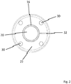
- Fig. 2 shows the front view of the connection of stub shaft 16 and drive shaft 20.
- the clamping device 22 is connected via the stub shaft 16 of the rotary piston (not shown) with the drive shaft 20.
- the recess 32 is almost closed, so that the stub shaft 16 frictionally, is pressed onto the drive shaft 20.
- Fig. 3 shows the positioning and synchronization of the rotary piston 12 with the template 40.
- the rotary piston 12 can be seen.
- the template 40 is fixed with the screws 28 on the pump housing 11.
- the rotary pistons 12 are positioned and synchronized.
- the spacer 44 With the help of the spacer 44, the distance is set, the rotary piston 12 after disassembly of the template 40 to the pump cover (not shown) need.
- Fig. 4 and 5 show a template according to the invention 40.
- the template 40 consists of a base body 41 having an inner side 46 and an outer side 47. On the outer side 47 eyelets 50 are arranged, with which the template 40 (not shown) in positioning and synchronizing the rotary piston on the pump housing and when not in use on the pump cover can be attached.
- On the inside 46 guides 42 are arranged, with which the rotary piston (not shown) are guided during positioning and synchronization in the rotary piston pump.
- the guides 42 are provided in the lower area in the vicinity of the main body 41 of the template 40 with projections 48.
- a plurality of spacers 44 are placed on the inner side 46 of the template 40. With the spacers 44 and the projections 48, a distance of the template 40 is ensured to the rotary piston when positioning and synchronizing the rotary piston in the rotary piston pump. This distance is needed to compensate for the thickness of the lining of the pump cover.
- Fig. 6 shows a template according to the invention 40 with rotary piston 12.
- a rotary lobe pump (not shown) are guided by the guides 42 and synchronized.
- the required distance that the rotary pistons 12 must have from the template 40 in positioning and synchronizing is ensured by the height / thickness of the spacers 20 and the projections 48.
- Fig. 7 shows the interaction of the template 40 with the rotary piston 12.
- the rotary piston 12 are inserted into the template 40 and are guided by the guides (not shown) and synchronized. Particularly well, the position of the rotary piston 12 to recognize each other, which can recognize a good synchronization for the embodiment shown. The position and orientation of the rotary piston 12 in the rotary pump will not be changed later, after removing the template 40.
- Fig. 8 and 9 shows the location of the template 40 when not in use on a rotary pump 10. If the template 40 is not needed for positioning and synchronizing the rotary piston (not shown), this can be fixed and stored on the outside of the rotary pump 10 space-saving and safe. By means of the eyelets 50, the template 40 is attached to the pump cover 26 of the rotary lobe pump 10. By the screws 28, the template 40 is fixed to the rotary lobe pump 10. This type of storage ensures that the correct template 40 is always present when rotary pistons in the rotary pump 10 have to be positioned and synchronized.
Landscapes
- Engineering & Computer Science (AREA)
- Mechanical Engineering (AREA)
- General Engineering & Computer Science (AREA)
- Details And Applications Of Rotary Liquid Pumps (AREA)
- Reciprocating Pumps (AREA)
- Details Of Reciprocating Pumps (AREA)
Description
- Die vorliegende Erfindung betrifft ein Verfahren und eine Vorrichtung zum Fixieren und Synchronisieren von Drehkolben in einer Drehkolbenpumpe.
- Das deutsche Patent
DE 197 56 838 C1 offenbart eine Drehkolbenpumpe mit mehreren auf parallelen Wellen angeordneten Drehkolbenpaaren. Diese Drehkolben rotieren berührungsfrei und zentrisch in kreisförmigen Gehäuseabschnitten, welche die Pumpenkammern bilden. Die Drehkolben sind über Nut-Feder-Verbindungen mit der jeweiligen zugeordneten Welle drehfest verbunden. Hierzu ist jeweils eine Passfeder vorgesehen, die einerseits in eine Wellennut und andererseits in eine Nut des Drehkolbens eingreift. - Die deutsche Patentanmeldung
DE 198 06 657 A1 offenbart eine Rotorpumpe mit einem im Querschnitt ovalen Pumpengehäuse, mit einem Paar von im Gehäuse auf zwei parallelen, gegensinnig drehantreibbaren Wellen angeordneten, ineinandergreifenden Rotoren, welche jeweils zwei oder mehr Verdrängerflügel aufweisen. Die Verdrängerflügel laufen, bei der Drehung der Rotoren dichtend an der Innenseite der Wandung des Pumpengehäuses und am jeweils anderen Rotor anliegend, um. Die Rotoren sind in Längsrichtung der Wellen von diesen bei geöffnetem Pumpengehäuse abziehbar, wobei die Wellen über Drehmomentübertragungsmittel, wie ein Paar von miteinander kämmenden Zahnrädern oder einen Ketten- oder Riementrieb, miteinander gekoppelt sind. Eine der Wellen ist mit einem Antriebsmotor verbindbar. Die Rotorpumpe gemäß Erfindung ist dadurch gekennzeichnet, dass die Drehmomentübertragungsmittel mit einer im Grundzustand eingerückten und bedarfsweise außer Eingriff bringbaren Kupplung ausgebildet sind. - Das Dokument
WO 2010 021549 offenbart eine Vorrichtung zum Ausrichten einer Exzenterpumpe. - Aus dem Dokument
US 2010 124512 ist eine Schablone bekannt, mittels welcher die rotatorische Position der Rotoren einer Zahnradpumpe justiert werden kann. - Der Erfindung liegt die Aufgabe zugrunde, ein Verfahren zu schaffen, mit welchem die Drehkolben einer Drehkolbenpumpe fixiert und im Pumpenraum ausgerichtet und synchronisiert werden können.
- Die erfindungsgemäße Aufgabe wird durch ein Verfahren gelöst, das die Merkmale des Anspruchs 1 umfasst. Weitere vorteilhafte Ausgestaltungen sind den Merkmalen der Unteransprüche zu entnehmen.
- Eine weitere Aufgabe der Erfindung betrifft eine Vorrichtung, mit welcher die Drehkolben in einer Drehkolbenpumpe positionier- und synchronisierbar sind.
- Diese Aufgabe wird durch eine Schablone gelöst, welche die Merkmale des Anspruches 5 umfasst.
- Es ist ein Verfahren zum Fixieren und Synchronisieren von Drehkolben in einer Drehkolbenpumpe offenbart. Die Drehkolben werden in einen Pumpenraum der Drehkolbenpumpe eingebracht. Anschließend wird ein Wellenstumpf, eines jeden Drehkolbens, durch eine Pumpenrückwand auf eine für den jeweiligen Drehkolben vorgesehene Antriebswelle geschoben. Die Drehkolben werden mit einer Schablone im Pumpenraum ausgerichtet und synchronisiert, wobei die Schablone an einem Pumpengehäuse lösbar fixiert wird. Die Wellenstümpfe des jeweiligen Drehkolbens werden nach dem synchronisieren, jeweils mittels einer Klemmeinrichtung kraftschlüssig mit der jeweiligen Antriebswelle, außerhalb des Pumpenraumes, verbunden.
- Die Verbindungen zwischen den Wellenstümpfen und den Antriebswellen werden durch jeweils eine Dichtung gegen den Pumpenraum abgedichtet. Die Dichtungen werden, vor dem Einbringen der Drehkolben in den Pumpenraum, lösbar auf die Wellenstümpfen der Drehkolben aufgeschoben und dort fixiert.
- Die Schablone wird mittels Führungen an die Drehkolben angelegt. Der Abstand, der nach dem Einbau der Drehkolben für eine Auskleidung eines Pumpendeckels benötigen wird, wird durch mindestens zwei Abstandshalter an der Innenseite der Schablone und durch Vorsprünge an den Führungen simuliert. Der benötigte Abstand zwischen den Drehkolben und der Pumpenrückwand wird durch die Dichtungen eingestellt. Dies geschieht dadurch, dass die Dichtung minimal in den Pumpenraum hinein ragt.
- Die Schablone wird mit mindestens zwei Ösen, die an einem Grundkörper der Schablone angeordnet sind, bei Nichtgebrauch, an dem Pumpendeckel befestigt. Bei diesen Ösen handelt es sich um dieselben Ösen, mit denen die Schablone beim Positionieren und Synchronisieren am Pumpengehäuse befestigt wird.
- Weiterhin ist eine Schablone zum Positionieren und/oder Synchronisieren von Drehkolben in einer Drehkolbenpumpe offenbart. Die Schablone besteht aus einem Grundkörper, an welchen mehrere Führungen angeordnet sind. Mit der Schablone sind feste Positionen der Drehkolben einstellbar.
- Es ist möglich, mit der Schablone sowohl zweiflügelige Drehkolben als auch mehrflügelige Drehkolben zu handhaben. Weiterhin sind mit der Schablone sowohl glatte als auch gewendelte Drehkolben in der Drehkolbenpumpe positionier- und/oder synchronisierbar. Dies ist möglich, weil die Führungen als Schienen oder als Stifte ausgestaltet sind. In den bevorzugten Ausführungsformen werden Schienen beschrieben, die an die Drehkolben angelegt sind und diese an den Längsseiten führen. Durch diese exakte Führung ist ein Verdrehen der Drehkolben ausgeschlossen. Für die Positionierung und Synchronisierung von mehrflügeligen Drehkolben werden Stifte oder Bolzen bevorzugt. Zusätzlich können noch kleinere Führungsschienen eingesetzt werden, so dass auch bei mehrflügeligen Drehkolben eine Verdrehung beim Einsatz der Schablone nicht möglich ist.
- In einer besonderen Ausführungsform ist es möglich, die Führungen in der Länge, also in die Pumpe hinein, variabel zu gestalten. Durch die Möglichkeit der Längenänderung ist es dann möglich auch Drehkolben und/oder Drehkolbenpaare zu positionieren und/oder zu synchronisieren, die in zweiter Reihe im Pumpenraum platziert sind.
- Der Grundkörper der Schablone besitzt mindestens zwei Ösen, mit welchen die Schablone beim Positionieren und Synchronisieren der Drehkolben an einem Pumpengehäuse und beim Nichtgebrauch an einem Pumpendeckel fixierbar ist.
- Für die Verwendung im erfindungsgemäßen Verfahren sind Drehkolben für eine Drehkolbenpumpe offenbart, wobei diese Drehkolben jeweils einen Wellenstumpf besitzen, der fest mit dem Drehkolben verbunden ist. Vor dem Einbau des Drehkolbens in eine Drehkolbenpumpe, wird eine Dichtung lösbar auf dem Wellenstumpft angeordnet und dort fixiert. Die Dichtung ist eine Gleitringdichtung oder eine Stopfbuchse oder eine Lippendichtung.
- Im Folgenden sollen Ausführungsbeispiele die Erfindung und ihre Vorteile anhand der beigefügten Figuren näher erläutern. Die Größenverhältnisse der einzelnen Elemente zueinander in den Figuren entsprechen nicht immer den realen Größenverhältnissen, da einige Formen vereinfacht und andere Formen zur besseren Veranschaulichung vergrößert im Verhältnis zu anderen Elementen dargestellt sind.
-
Fig. 1 zeigt einen erfindungsgemäß eingebauten Drehkolben mit Klemmeinrichtung. -
Fig. 2 zeigt die Frontansicht der Verbindung von Wellenstumpf und Antriebswelle. -
Fig. 3 zeigt die Positionierung und Synchronisierung der Drehkolben mit der Schablone. -
Fig. 4 und5 zeigen eine erfindungsgemäße Schablone. -
Fig. 6 zeigt eine erfindungsgemäße Schablone mit Drehkolben. -
Fig. 7 zeigt das Zusammenspiel der Schablone mit Drehkolben. -
Fig. 8 und9 zeigen die Lage der Schablone bei nichtgebrauch an einer Drehkolbenpumpe. -
Fig. 1 zeigt einen erfindungsgemäß eingebauten Drehkolben 12 mit Klemmeinrichtung 22. Der Drehkolben 12 ist im Pumpenraum 14 der Drehkolbenpumpe 10 angeordnet. An der, der Pumpenrückwand 18 zugewandten Seite des Drehkolbens 12 ist ein Wellenstumpf 16 angeordnet. Dieser Wellenstumpf 16 ist mit einer Dichtung 24 versehen und ist über die Antriebswelle 20 geschoben. Weiterhin ist am äußeren Ende 17 des Wellenstumpfes 16 eine Klemmeinrichtung 22 angeordnet. Mit dieser Klemmeinrichtung 22 werden der Wellenstumpf 16 und die Antriebswelle 20 kraftschlüssig, lösbar miteinander verbunden. Durch das Anziehen der Spannschrauben 30 wird die Klemmeinrichtung 22 in eine Hülse 23 hineingepresst. Durch diese Verpressung wird die Klemmeinrichtung 22 an der Außenseite 34 gegen die Hülse 23 und an der Innenseite 36 gegen den Wellenstumpf 16 gepresst. Der Wellenstumpf 16 wird hierdurch auf die Antriebswelle 20 gepresst und mit dieser kraftschlüssig in Wirkzusammenhang gebracht. - Die Klemmeinrichtung 22 arbeitet somit mechanisch über Teile mit konischen Flächen und führt bei der Betätigung der Spannschrauben 30 zu einer Reduzierung des inneren Querschnitts der ringförmigen ineinandergreifenden Bauteile. Die Bauteile sind in der beschriebenen Ausführungsform die Antriebswelle 20 und der Wellenstumpf 16.
-
Fig. 2 zeigt die Frontansicht der Verbindung von Wellenstumpf 16 und Antriebswelle 20. Die Klemmeinrichtung 22 ist über den Wellenstumpf 16 des Drehkolbens (nicht dargestellt) mit der Antriebswelle 20 verbunden. Durch das Anziehen der Spannschrauben 30 wird die Aussparung 32 nahezu geschlossen, so dass der Wellenstumpf 16 kraftschlüssig, auf die Antriebswelle 20 aufgepresst wird. -
Fig. 3 zeigt die Positionierung und Synchronisierung der Drehkolben 12 mit der Schablone 40. Im Pumpenraum 14 sind die Drehkolben 12 zu erkennen. Die Schablone 40 ist mit den Schrauben 28 am Pumpengehäuse 11 fixiert. Durch die Führungen 42 werden die Drehkolben 12 positioniert und synchronisiert. Mit Hilfe der Abstandshalter 44 wird der Abstand eingestellt, den die Drehkolben 12 nach der Demontage der Schablone 40 zum Pumpendeckel (nicht dargestellt) benötigen. -
Fig. 4 und5 zeigen eine erfindungsgemäße Schablone 40. Die Schablone 40 besteht aus einem Grundkörper 41 der eine Innenseite 46 und eine Außenseite 47 aufweist. An der Außenseite 47 sind Ösen 50 angeordnet, mit welchen die Schablone 40 beim Positionieren und Synchronisieren der Drehkolben (nicht dargestellt) am Pumpengehäuse und bei Nichtgebrauch am Pumpendeckel befestigt werden kann. An der Innenseite 46 sind Führungen 42 angeordnet, mit welchen die Drehkolben (nicht dargestellt) beim Positionieren und Synchronisieren in die Drehkolbenpumpe geführt werden. Die Führungen 42 sind im unteren Bereich in der Nähe zum Grundkörper 41 der Schablone 40 mit Vorsprüngen 48 versehen. Weiterhin sind an der Innenseite 46 der Schablone 40 mehrere Abstandshalter 44 platziert. Mit den Abstandshaltern 44 und den Vorsprüngen 48 wird beim Positionieren und Synchronisieren der Drehkolben in der Drehkolbenpumpe ein Abstand der Schablone 40 zu den Drehkolben sichergestellt. Dieser Abstand wird benötigt zum Ausgleich der Dicke der Auskleidung des Pumpendeckels. -
Fig. 6 zeigt eine erfindungsgemäße Schablone 40 mit Drehkolben 12. Beim Positionieren und Synchronisieren der Drehkolben 12 in einer Drehkolbenpumpe (nicht dargestellt) werden diese von den Führungen 42 geführt und synchronisiert. Der benötigte Abstand, den die Drehkolben 12 von der Schablone 40 beim Positionieren und Synchronisieren haben müssen, wird durch die Höhe/Dicke der Abstandshalter 20 und die Vorsprünge 48 sichergestellt. -
Fig. 7 zeigt das Zusammenspiel der Schablone 40 mit den Drehkolben 12. Die Drehkolben 12 sind in die Schablone 40 eingebracht und werden durch die Führungen (nicht dargestellt) geführt und synchronisiert. Besonders gut ist die Position der Drehkolben 12 zueinander zu erkennen, welche eine für die gezeigte Ausführungsform gute Synchronisierung erkennen lässt. Die Lage und Ausrichtung der Drehkolben 12 in der Drehkolbenpumpe wird später, nach dem Entfernen der Schablone 40, nicht mehr verändert werden. -
Fig. 8 und9 zeigt die Lage der Schablone 40 bei Nichtgebrauch an einer Drehkolbenpumpe 10. Wenn die Schablone 40 nicht zum Positionieren und Synchronisieren der Drehkolben (nicht dargestellt) benötigt wird, kann diese platzsparend und sicher an der Außenseite der Drehkolbenpumpe 10 befestigt und gelagert werden. Mittels der Ösen 50 wird die Schablone 40 am Pumpendeckel 26 der Drehkolbenpumpe 10 befestigt. Durch die Schrauben 28 wird die Schablone 40 an der Drehkolbenpumpe 10 fixiert. Durch diese Art der Aufbewahrung ist sichergestellt, dass immer die richtige Schablone 40 vorhanden ist, wenn Drehkolben in der Drehkolbenpumpe 10 positioniert und synchronisiert werden müssen. - Die Erfindung wurde unter Bezugnahme auf eine bevorzugte Ausführungsform beschrieben.
-
- 10
- Drehkolbenpumpe
- 11
- Pumpengehäuse
- 12
- Drehkolben
- 14
- Pumpenraum
- 16
- Wellenstumpf
- 17
- Äußeres Ende
- 18
- Pumpenrückwand
- 20
- Antriebswelle
- 22
- Klemmeinrichtung
- 23
- Hülse
- 24
- Dichtung
- 26
- Pumpendeckel
- 28
- Schraube
- 30
- Spannschraube
- 32
- Aussparung
- 34
- Außenseite der Klemmeinrichtung
- 36
- Innenseite der Klemmeinrichtung
- 40
- Schablone
- 41
- Grundkörper
- 42
- Führungen
- 44
- Abstandhalter
- 46
- Innenseite der Schablone
- 47
- Außenseite der Schablone
- 48
- Vorsprünge der Führungen
- 50
- Öse
Claims (10)
- Verfahren zum Fixieren und Synchronisieren von Drehkolben (12) in einer Drehkolbenpumpe (10) dadurch gekennzeichnet, dassdie Drehkolben (12) in einen Pumpenraum (14) der Drehkolbenpumpe (10) eingebracht werden;
 ein Wellenstumpf (16), eines jeden Drehkolbens (12), durch eine Pumpenrückwand (18) und auf eine für den jeweiligen Drehkolben (12) vorgesehene Antriebswellen (20) geschoben wird;die Drehkolben (12) mit einer Schablone (40) im Pumpenraum (14) ausgerichtet und synchronisiert werden, wobei die Schablone (40) an einem Pumpengehäuse (11) lösbar fixiert wird,die Wellenstümpfe (16) des jeweiligen Drehkolbens (12) nach dem synchronisieren, jeweils mittels einer Klemmeinrichtung (22) kraftschlüssig mit der jeweiligen Antriebswelle (20) außerhalb des Pumpenraumes (14) verbunden werden,die Schablone (40) mittels Führungen (42) an die Drehkolben (12) angelegt wird undder Abstand, der nach dem Einbau der Drehkolben (12) für eine Auskleidung und für ein Pumpendeckel (26) benötigen wird, durch mindesten zwei Abstandhalter (44) an der Innenseite (46) der Schablone (40) und durch Vorsprünge (48) an den Führungen (42) simuliert wird.
 - Verfahren nach Anspruch 1, dadurch gekennzeichnet, dass Dichtungen (24), vor dem Einbringen der Drehkolben (12) in den Pumpenraum (14), lösbar auf die Wellenstümpfen (16) der Drehkolben (12) aufgeschoben und dort fixiert werden.
- Verfahren nach einem der Anspruch 1 oder 2, dadurch gekennzeichnet, dass der benötigte Abstand zwischen den Drehkolben (12) und der Pumpenrückwand (18) durch die Dichtungen (24) eingestellt wird.
- Verfahren nach einem der Ansprüche 1 bis 3, dadurch gekennzeichnet, dass die Schablone (40) mit mindestens zwei Ösen (50), die an einem Grundkörper (41) der Schablone (40) angeordnet sind, bei Nichtgebrauch, an dem Pumpendeckel (26) befestigt wird.
- Schablone (40) zum Positionieren und/oder Synchronisieren von Drehkolben (12) in einer Drehkolbenpumpe (10), dadurch gekennzeichnet, dass die Schablone (40) aus einem Grundkörper (41) besteht, an welchen mehrere Führungen (42) und an dessen Innenseite (46) mindestens zwei Abstandshalter (44) angeordnet sind, wobei die Führungen (42) bei der Montage an die Längsseiten der Drehkolben (12) angelegt sind und wobei durch die mindestens zwei Abstandshalter (44) ein Abstand zwischen den Drehkolben (12) und dem Grundkörper (41) der Schablone (40) sichergestellt ist.
- Schablone (40) nach Anspruch 5, dadurch gekennzeichnet, dass die Führungen (42) Schienen und/oder Stifte und/oder Bolzen sind.
- Schablone (40) nach einem der Ansprüche 5 oder 6, dadurch gekennzeichnet, dass mit der Schablone (40) feste Positionen der Drehkolben (12) einstellbar sind.
- Schablone (40) nach einem der Ansprüche 5 bis 7, dadurch gekennzeichnet, dass mit der Schablone (40) sowohl zweiflügelige Drehkolben (12) als auch mehrflügelige Drehkolben (12) handhabbar sind.
- Schablone (40) nach eine der Ansprüche 5 bis 8, dadurch gekennzeichnet, dass mit der Schablone (40) sowohl glatte als auch gewendelte Drehkolben (12) in der Drehkolbenpumpe (10) positionierbar und/oder synchronisierbar sind.
- Schablone (40) nach eine der Ansprüche 5 bis 9, dadurch gekennzeichnet, dass der Grundkörper (41) der Schablone (40) mindestens zwei Ösen (50) besitzt, mit welchen die Schablone (40) beim Positionieren und Synchronisieren der Drehkolben (12) an einem Pumpengehäuse (11) und beim Nichtgebrauch an einem Pumpendeckel (26) fixierbar ist.
Applications Claiming Priority (2)
| Application Number | Priority Date | Filing Date | Title |
|---|---|---|---|
| DE102012003066A DE102012003066B3 (de) | 2012-02-17 | 2012-02-17 | Verfahren und vorrichtung zum fixieren und synchronisieren von drehkolben in einer drehkolbenpumpe |
| PCT/DE2013/100056 WO2013120488A2 (de) | 2012-02-17 | 2013-02-14 | Verfahren und vorrichtung zum fixieren und synchronisieren von drehkolben in einer drehkolbenpumpe |
Publications (2)
| Publication Number | Publication Date |
|---|---|
| EP2815128A2 EP2815128A2 (de) | 2014-12-24 |
| EP2815128B1 true EP2815128B1 (de) | 2019-05-08 |
Family
ID=48224774
Family Applications (1)
| Application Number | Title | Priority Date | Filing Date |
|---|---|---|---|
| EP13719269.6A Active EP2815128B1 (de) | 2012-02-17 | 2013-02-14 | Verfahren und vorrichtung zum fixieren und synchronisieren von drehkolben in einer drehkolbenpumpe |
Country Status (9)
| Country | Link |
|---|---|
| US (1) | US9611850B2 (de) |
| EP (1) | EP2815128B1 (de) |
| JP (1) | JP6034409B2 (de) |
| KR (1) | KR20140125378A (de) |
| CN (1) | CN104114866B (de) |
| BR (1) | BR112014019542B1 (de) |
| DE (1) | DE102012003066B3 (de) |
| TW (1) | TWI611105B (de) |
| WO (1) | WO2013120488A2 (de) |
Families Citing this family (1)
| Publication number | Priority date | Publication date | Assignee | Title |
|---|---|---|---|---|
| DE102014117166B4 (de) | 2014-11-24 | 2016-07-07 | Netzsch Pumpen & Systeme Gmbh | Drehkolbenpumpe, verfahren zur fixierung von drehkolben einer drehkolbenpumpe und verfahren zur demontage von drehkolben einer drehkolbenpumpe |
Family Cites Families (25)
| Publication number | Priority date | Publication date | Assignee | Title |
|---|---|---|---|---|
| US2044930A (en) * | 1933-12-11 | 1936-06-23 | Zubaty Joseph | Synchronized driving mechanism |
| US3105634A (en) * | 1960-12-27 | 1963-10-01 | Polysius Gmbh | Rotary piston for a roots blower |
| US3620338A (en) * | 1968-10-21 | 1971-11-16 | Ohaza Ohbayashi | Synchronizing speed change gears |
| IT8267502A0 (it) * | 1982-04-15 | 1982-04-15 | Torino A | Compressore volumetrico rotativo del tipo roots e attrezzo utilizzabile per l assemblaggio di tale compressore |
| DE3721398A1 (de) * | 1987-06-29 | 1989-01-19 | Bornemann J H Gmbh & Co | Foerderaggregat bestehend aus einer pumpe mit einer antriebseinrichtung |
| DE19756838C1 (de) * | 1997-12-19 | 1999-04-15 | K Busch Gmbh Druck & Vakuum Dr | Drehkolbenpumpe |
| DE19806657C2 (de) * | 1998-02-18 | 2000-08-10 | Boerger Gmbh | Rotorpumpe |
| EP0953769B1 (de) * | 1998-04-27 | 2004-01-07 | Allweiler AG | Exzenterschneckenpumpe |
| US6604503B2 (en) * | 1998-06-15 | 2003-08-12 | M.R. Engines Ltd. | Rotary machine |
| CN2348151Y (zh) * | 1998-09-19 | 1999-11-10 | 丹东市油泵厂 | 回转容积式罗茨油泵 |
| US6093009A (en) * | 1999-02-17 | 2000-07-25 | Jacks, Jr.; Morris G. | Apparatus and method for controlling angular relation between two rotating shafts |
| DE20013338U1 (de) * | 2000-08-02 | 2000-12-28 | Werner Rietschle GmbH + Co. KG, 79650 Schopfheim | Verdichter |
| JP2002122085A (ja) * | 2000-10-16 | 2002-04-26 | Toyota Industries Corp | 真空ポンプにおける流路構造 |
| US6716011B2 (en) * | 2001-06-14 | 2004-04-06 | Monarch Hydraulics, Inc. | Hydraulic pump utilizing floating shafts |
| DE20305937U1 (de) * | 2003-04-12 | 2004-05-19 | Hugo Vogelsang Maschinenbau Gmbh | Pumpe mit integriertem Hydraulik-Motor |
| WO2005045197A1 (de) * | 2003-10-29 | 2005-05-19 | Sl-Trade Marks Gmbh | Kreiskolben-wärmemotor-vorrichtung |
| CA2450542C (en) * | 2003-11-21 | 2011-01-04 | Anatoly Arov | Arov engine/pump |
| GB2440944B (en) * | 2006-08-11 | 2011-10-12 | Itt Mfg Enterprises Inc | Rotary lobe pump |
| JP2008157446A (ja) * | 2006-11-30 | 2008-07-10 | Anest Iwata Corp | 2軸以上の回転軸間の駆動力伝達機構と該駆動力伝達機構を用いた無給油流体機械 |
| NO329714B1 (no) * | 2008-08-21 | 2010-12-06 | Agr Subsea As | Ytre rotor i eksenterskruepumpe med en indre og en ytre rotor |
| US8177535B2 (en) * | 2008-11-19 | 2012-05-15 | Equistar Chemicals, Lp | Method for timing a polymer pump containing polymer |
| GB2468876B (en) * | 2009-03-25 | 2011-06-29 | Environmental Mfg Llp | A rotary mechanism |
| DE102010014248B4 (de) * | 2010-04-08 | 2016-04-28 | Netzsch Pumpen & Systeme Gmbh | Kontaktelemente für Drehkolbenpumpen |
| US9003633B1 (en) * | 2011-08-19 | 2015-04-14 | Agostino Difante | Concrete anchor bolt fastener and tool and method for installing |
| WO2015156705A2 (en) * | 2015-05-06 | 2015-10-15 | Zakrytoe Aktsionernoe Obschestvo "Diakont" | Transmission gear, roller reducer comprising the transmission gear, and method of assembly thereof |
-
2012
- 2012-02-17 DE DE102012003066A patent/DE102012003066B3/de active Active
-
2013
- 2013-02-14 EP EP13719269.6A patent/EP2815128B1/de active Active
- 2013-02-14 KR KR1020147022531A patent/KR20140125378A/ko not_active Ceased
- 2013-02-14 JP JP2014556923A patent/JP6034409B2/ja active Active
- 2013-02-14 BR BR112014019542-0A patent/BR112014019542B1/pt active IP Right Grant
- 2013-02-14 CN CN201380009428.6A patent/CN104114866B/zh active Active
- 2013-02-14 WO PCT/DE2013/100056 patent/WO2013120488A2/de not_active Ceased
- 2013-02-18 TW TW102105592A patent/TWI611105B/zh not_active IP Right Cessation
-
2014
- 2014-08-06 US US14/453,264 patent/US9611850B2/en active Active
Non-Patent Citations (1)
| Title |
|---|
| None * |
Also Published As
| Publication number | Publication date |
|---|---|
| DE102012003066B3 (de) | 2013-07-04 |
| EP2815128A2 (de) | 2014-12-24 |
| US20140345451A1 (en) | 2014-11-27 |
| KR20140125378A (ko) | 2014-10-28 |
| JP6034409B2 (ja) | 2016-11-30 |
| TWI611105B (zh) | 2018-01-11 |
| CN104114866B (zh) | 2016-11-16 |
| JP2015508855A (ja) | 2015-03-23 |
| BR112014019542B1 (pt) | 2021-11-30 |
| WO2013120488A2 (de) | 2013-08-22 |
| BR112014019542A2 (de) | 2017-06-20 |
| BR112014019542A8 (pt) | 2017-07-11 |
| CN104114866A (zh) | 2014-10-22 |
| WO2013120488A3 (de) | 2014-04-17 |
| TW201400705A (zh) | 2014-01-01 |
| US9611850B2 (en) | 2017-04-04 |
Similar Documents
| Publication | Publication Date | Title |
|---|---|---|
| EP2634366B1 (de) | Zweispindelige Schraubenspindelpumpe in einflutiger Bauweise mit Zahnrädern, mittels derer die Spindeln drehgekoppelt sind. | |
| AT513496A4 (de) | Taumelgetriebe | |
| DE102012005949B4 (de) | Zweispindelige Schraubenspindelpumpe in zweiflutiger Bauweise | |
| EP2606234A2 (de) | Drehkolbenpumpe | |
| DE102014002396A1 (de) | Zweispindelige Schraubenspindelpumpe in einflutiger Bauweise | |
| DE202014007117U1 (de) | Klauenpumpe | |
| EP3404289A1 (de) | Mit einem kettenantrieb betätigbare schiebesteife schubkette | |
| DE102012003066B3 (de) | Verfahren und vorrichtung zum fixieren und synchronisieren von drehkolben in einer drehkolbenpumpe | |
| DE112015006118B4 (de) | Toleranzunabhängige Halbmond-Innenzahnradpumpe | |
| EP3224478B1 (de) | Drehkolbenpumpe, verfahren zur fixierung von drehkolben einer drehkolbenpumpe und verfahren zur demontage von drehkolben einer drehkolbenpumpe | |
| DE102012217115A1 (de) | Zahnradmaschine mit von der Kreisform abweichendem Niederdruckanschluss | |
| EP2556256B1 (de) | Drehkolbenpumpe und verfahren zum betreiben einer drehkolbenpumpe | |
| EP2522297B1 (de) | Zahnärztliches Handinstrument mit länglicher Griffhülse | |
| DE102012104804A1 (de) | Verdrängerpumpe | |
| DE102015209833B4 (de) | Zahnradmaschine | |
| EP3499040B1 (de) | Schraubenvakuumpumpe | |
| DE19802264C1 (de) | Rotorpumpe | |
| DE202012000894U1 (de) | Zweispindelige Schraubenspindelpumpe in einflutiger Bauweise | |
| DE102012001699B4 (de) | Zweispindelige Schraubenspindelpumpe in einflutiger Bauweise | |
| EP3328252B1 (de) | Elektromotorisches küchengerät mit kupplung | |
| DE102013110091B3 (de) | Wälzkolbenpumpe mit zwei Rotoren | |
| EP3118456B1 (de) | Kunststoffrotor für vakuumpumpe | |
| DE102013219945A1 (de) | Anordnung für einen Verbrennungsmotor eines Kraftfahrzeuges umfassend eine erste Pumpe, eine Ausgleichswelle und eine zweite Pumpe sowie Verfahren zur Montage einer Ausgleichswelle in einem Gehäuse | |
| DE202012003018U1 (de) | Zweispindelige Schraubenspindelpumpe in zweiflutiger Bauweise | |
| DE102014223082A1 (de) | Getriebegehäuse mit abnehmbarem Nebengehäuseteil zur erleichterten Gummilagermontage |
Legal Events
| Date | Code | Title | Description |
|---|---|---|---|
| PUAI | Public reference made under article 153(3) epc to a published international application that has entered the european phase |
Free format text: ORIGINAL CODE: 0009012 |
|
| 17P | Request for examination filed |
Effective date: 20141017 |
|
| AK | Designated contracting states |
Kind code of ref document: A2 Designated state(s): AL AT BE BG CH CY CZ DE DK EE ES FI FR GB GR HR HU IE IS IT LI LT LU LV MC MK MT NL NO PL PT RO RS SE SI SK SM TR |
|
| AX | Request for extension of the european patent |
Extension state: BA ME |
|
| DAX | Request for extension of the european patent (deleted) | ||
| STAA | Information on the status of an ep patent application or granted ep patent |
Free format text: STATUS: EXAMINATION IS IN PROGRESS |
|
| 17Q | First examination report despatched |
Effective date: 20180928 |
|
| GRAP | Despatch of communication of intention to grant a patent |
Free format text: ORIGINAL CODE: EPIDOSNIGR1 |
|
| STAA | Information on the status of an ep patent application or granted ep patent |
Free format text: STATUS: GRANT OF PATENT IS INTENDED |
|
| INTG | Intention to grant announced |
Effective date: 20190221 |
|
| GRAS | Grant fee paid |
Free format text: ORIGINAL CODE: EPIDOSNIGR3 |
|
| GRAA | (expected) grant |
Free format text: ORIGINAL CODE: 0009210 |
|
| STAA | Information on the status of an ep patent application or granted ep patent |
Free format text: STATUS: THE PATENT HAS BEEN GRANTED |
|
| AK | Designated contracting states |
Kind code of ref document: B1 Designated state(s): AL AT BE BG CH CY CZ DE DK EE ES FI FR GB GR HR HU IE IS IT LI LT LU LV MC MK MT NL NO PL PT RO RS SE SI SK SM TR |
|
| REG | Reference to a national code |
Ref country code: GB Ref legal event code: FG4D Free format text: NOT ENGLISH |
|
| REG | Reference to a national code |
Ref country code: CH Ref legal event code: EP Ref country code: AT Ref legal event code: REF Ref document number: 1130544 Country of ref document: AT Kind code of ref document: T Effective date: 20190515 |
|
| REG | Reference to a national code |
Ref country code: IE Ref legal event code: FG4D Free format text: LANGUAGE OF EP DOCUMENT: GERMAN |
|
| REG | Reference to a national code |
Ref country code: DE Ref legal event code: R096 Ref document number: 502013012796 Country of ref document: DE |
|
| REG | Reference to a national code |
Ref country code: NL Ref legal event code: MP Effective date: 20190508 |
|
| REG | Reference to a national code |
Ref country code: LT Ref legal event code: MG4D |
|
| PG25 | Lapsed in a contracting state [announced via postgrant information from national office to epo] |
Ref country code: SE Free format text: LAPSE BECAUSE OF FAILURE TO SUBMIT A TRANSLATION OF THE DESCRIPTION OR TO PAY THE FEE WITHIN THE PRESCRIBED TIME-LIMIT Effective date: 20190508 Ref country code: NL Free format text: LAPSE BECAUSE OF FAILURE TO SUBMIT A TRANSLATION OF THE DESCRIPTION OR TO PAY THE FEE WITHIN THE PRESCRIBED TIME-LIMIT Effective date: 20190508 Ref country code: LT Free format text: LAPSE BECAUSE OF FAILURE TO SUBMIT A TRANSLATION OF THE DESCRIPTION OR TO PAY THE FEE WITHIN THE PRESCRIBED TIME-LIMIT Effective date: 20190508 Ref country code: ES Free format text: LAPSE BECAUSE OF FAILURE TO SUBMIT A TRANSLATION OF THE DESCRIPTION OR TO PAY THE FEE WITHIN THE PRESCRIBED TIME-LIMIT Effective date: 20190508 Ref country code: FI Free format text: LAPSE BECAUSE OF FAILURE TO SUBMIT A TRANSLATION OF THE DESCRIPTION OR TO PAY THE FEE WITHIN THE PRESCRIBED TIME-LIMIT Effective date: 20190508 Ref country code: AL Free format text: LAPSE BECAUSE OF FAILURE TO SUBMIT A TRANSLATION OF THE DESCRIPTION OR TO PAY THE FEE WITHIN THE PRESCRIBED TIME-LIMIT Effective date: 20190508 Ref country code: HR Free format text: LAPSE BECAUSE OF FAILURE TO SUBMIT A TRANSLATION OF THE DESCRIPTION OR TO PAY THE FEE WITHIN THE PRESCRIBED TIME-LIMIT Effective date: 20190508 Ref country code: PT Free format text: LAPSE BECAUSE OF FAILURE TO SUBMIT A TRANSLATION OF THE DESCRIPTION OR TO PAY THE FEE WITHIN THE PRESCRIBED TIME-LIMIT Effective date: 20190908 Ref country code: NO Free format text: LAPSE BECAUSE OF FAILURE TO SUBMIT A TRANSLATION OF THE DESCRIPTION OR TO PAY THE FEE WITHIN THE PRESCRIBED TIME-LIMIT Effective date: 20190808 |
|
| PG25 | Lapsed in a contracting state [announced via postgrant information from national office to epo] |
Ref country code: GR Free format text: LAPSE BECAUSE OF FAILURE TO SUBMIT A TRANSLATION OF THE DESCRIPTION OR TO PAY THE FEE WITHIN THE PRESCRIBED TIME-LIMIT Effective date: 20190809 Ref country code: LV Free format text: LAPSE BECAUSE OF FAILURE TO SUBMIT A TRANSLATION OF THE DESCRIPTION OR TO PAY THE FEE WITHIN THE PRESCRIBED TIME-LIMIT Effective date: 20190508 Ref country code: BG Free format text: LAPSE BECAUSE OF FAILURE TO SUBMIT A TRANSLATION OF THE DESCRIPTION OR TO PAY THE FEE WITHIN THE PRESCRIBED TIME-LIMIT Effective date: 20190808 Ref country code: RS Free format text: LAPSE BECAUSE OF FAILURE TO SUBMIT A TRANSLATION OF THE DESCRIPTION OR TO PAY THE FEE WITHIN THE PRESCRIBED TIME-LIMIT Effective date: 20190508 |
|
| PG25 | Lapsed in a contracting state [announced via postgrant information from national office to epo] |
Ref country code: DK Free format text: LAPSE BECAUSE OF FAILURE TO SUBMIT A TRANSLATION OF THE DESCRIPTION OR TO PAY THE FEE WITHIN THE PRESCRIBED TIME-LIMIT Effective date: 20190508 Ref country code: EE Free format text: LAPSE BECAUSE OF FAILURE TO SUBMIT A TRANSLATION OF THE DESCRIPTION OR TO PAY THE FEE WITHIN THE PRESCRIBED TIME-LIMIT Effective date: 20190508 Ref country code: RO Free format text: LAPSE BECAUSE OF FAILURE TO SUBMIT A TRANSLATION OF THE DESCRIPTION OR TO PAY THE FEE WITHIN THE PRESCRIBED TIME-LIMIT Effective date: 20190508 Ref country code: CZ Free format text: LAPSE BECAUSE OF FAILURE TO SUBMIT A TRANSLATION OF THE DESCRIPTION OR TO PAY THE FEE WITHIN THE PRESCRIBED TIME-LIMIT Effective date: 20190508 Ref country code: SK Free format text: LAPSE BECAUSE OF FAILURE TO SUBMIT A TRANSLATION OF THE DESCRIPTION OR TO PAY THE FEE WITHIN THE PRESCRIBED TIME-LIMIT Effective date: 20190508 |
|
| REG | Reference to a national code |
Ref country code: DE Ref legal event code: R097 Ref document number: 502013012796 Country of ref document: DE |
|
| PG25 | Lapsed in a contracting state [announced via postgrant information from national office to epo] |
Ref country code: SM Free format text: LAPSE BECAUSE OF FAILURE TO SUBMIT A TRANSLATION OF THE DESCRIPTION OR TO PAY THE FEE WITHIN THE PRESCRIBED TIME-LIMIT Effective date: 20190508 |
|
| PLBE | No opposition filed within time limit |
Free format text: ORIGINAL CODE: 0009261 |
|
| STAA | Information on the status of an ep patent application or granted ep patent |
Free format text: STATUS: NO OPPOSITION FILED WITHIN TIME LIMIT |
|
| PG25 | Lapsed in a contracting state [announced via postgrant information from national office to epo] |
Ref country code: TR Free format text: LAPSE BECAUSE OF FAILURE TO SUBMIT A TRANSLATION OF THE DESCRIPTION OR TO PAY THE FEE WITHIN THE PRESCRIBED TIME-LIMIT Effective date: 20190508 |
|
| 26N | No opposition filed |
Effective date: 20200211 |
|
| PG25 | Lapsed in a contracting state [announced via postgrant information from national office to epo] |
Ref country code: PL Free format text: LAPSE BECAUSE OF FAILURE TO SUBMIT A TRANSLATION OF THE DESCRIPTION OR TO PAY THE FEE WITHIN THE PRESCRIBED TIME-LIMIT Effective date: 20190508 |
|
| PG25 | Lapsed in a contracting state [announced via postgrant information from national office to epo] |
Ref country code: SI Free format text: LAPSE BECAUSE OF FAILURE TO SUBMIT A TRANSLATION OF THE DESCRIPTION OR TO PAY THE FEE WITHIN THE PRESCRIBED TIME-LIMIT Effective date: 20190508 |
|
| REG | Reference to a national code |
Ref country code: CH Ref legal event code: PL |
|
| REG | Reference to a national code |
Ref country code: BE Ref legal event code: MM Effective date: 20200229 |
|
| PG25 | Lapsed in a contracting state [announced via postgrant information from national office to epo] |
Ref country code: MC Free format text: LAPSE BECAUSE OF FAILURE TO SUBMIT A TRANSLATION OF THE DESCRIPTION OR TO PAY THE FEE WITHIN THE PRESCRIBED TIME-LIMIT Effective date: 20190508 Ref country code: LU Free format text: LAPSE BECAUSE OF NON-PAYMENT OF DUE FEES Effective date: 20200214 |
|
| PG25 | Lapsed in a contracting state [announced via postgrant information from national office to epo] |
Ref country code: LI Free format text: LAPSE BECAUSE OF NON-PAYMENT OF DUE FEES Effective date: 20200229 Ref country code: CH Free format text: LAPSE BECAUSE OF NON-PAYMENT OF DUE FEES Effective date: 20200229 |
|
| PG25 | Lapsed in a contracting state [announced via postgrant information from national office to epo] |
Ref country code: IE Free format text: LAPSE BECAUSE OF NON-PAYMENT OF DUE FEES Effective date: 20200214 |
|
| PG25 | Lapsed in a contracting state [announced via postgrant information from national office to epo] |
Ref country code: BE Free format text: LAPSE BECAUSE OF NON-PAYMENT OF DUE FEES Effective date: 20200229 |
|
| REG | Reference to a national code |
Ref country code: AT Ref legal event code: MM01 Ref document number: 1130544 Country of ref document: AT Kind code of ref document: T Effective date: 20200214 |
|
| PG25 | Lapsed in a contracting state [announced via postgrant information from national office to epo] |
Ref country code: AT Free format text: LAPSE BECAUSE OF NON-PAYMENT OF DUE FEES Effective date: 20200214 |
|
| PG25 | Lapsed in a contracting state [announced via postgrant information from national office to epo] |
Ref country code: MT Free format text: LAPSE BECAUSE OF FAILURE TO SUBMIT A TRANSLATION OF THE DESCRIPTION OR TO PAY THE FEE WITHIN THE PRESCRIBED TIME-LIMIT Effective date: 20190508 Ref country code: CY Free format text: LAPSE BECAUSE OF FAILURE TO SUBMIT A TRANSLATION OF THE DESCRIPTION OR TO PAY THE FEE WITHIN THE PRESCRIBED TIME-LIMIT Effective date: 20190508 |
|
| PG25 | Lapsed in a contracting state [announced via postgrant information from national office to epo] |
Ref country code: MK Free format text: LAPSE BECAUSE OF FAILURE TO SUBMIT A TRANSLATION OF THE DESCRIPTION OR TO PAY THE FEE WITHIN THE PRESCRIBED TIME-LIMIT Effective date: 20190508 Ref country code: IS Free format text: LAPSE BECAUSE OF FAILURE TO SUBMIT A TRANSLATION OF THE DESCRIPTION OR TO PAY THE FEE WITHIN THE PRESCRIBED TIME-LIMIT Effective date: 20190908 |
|
| PGFP | Annual fee paid to national office [announced via postgrant information from national office to epo] |
Ref country code: GB Payment date: 20260226 Year of fee payment: 14 |
|
| PGFP | Annual fee paid to national office [announced via postgrant information from national office to epo] |
Ref country code: DE Payment date: 20260303 Year of fee payment: 14 |
|
| PGFP | Annual fee paid to national office [announced via postgrant information from national office to epo] |
Ref country code: IT Payment date: 20260227 Year of fee payment: 14 |
|
| PGFP | Annual fee paid to national office [announced via postgrant information from national office to epo] |
Ref country code: FR Payment date: 20260225 Year of fee payment: 14 |