EP2814942B1 - Microfluidic cartridge for processing and detecting nucleic acids - Google Patents
Microfluidic cartridge for processing and detecting nucleic acids Download PDFInfo
- Publication number
- EP2814942B1 EP2814942B1 EP13748851.6A EP13748851A EP2814942B1 EP 2814942 B1 EP2814942 B1 EP 2814942B1 EP 13748851 A EP13748851 A EP 13748851A EP 2814942 B1 EP2814942 B1 EP 2814942B1
- Authority
- EP
- European Patent Office
- Prior art keywords
- microfluidic cartridge
- top layer
- segment
- occlusion
- layer
- Prior art date
- Legal status (The legal status is an assumption and is not a legal conclusion. Google has not performed a legal analysis and makes no representation as to the accuracy of the status listed.)
- Active
Links
Images






Classifications
-
- C—CHEMISTRY; METALLURGY
- C12—BIOCHEMISTRY; BEER; SPIRITS; WINE; VINEGAR; MICROBIOLOGY; ENZYMOLOGY; MUTATION OR GENETIC ENGINEERING
- C12N—MICROORGANISMS OR ENZYMES; COMPOSITIONS THEREOF; PROPAGATING, PRESERVING, OR MAINTAINING MICROORGANISMS; MUTATION OR GENETIC ENGINEERING; CULTURE MEDIA
- C12N15/00—Mutation or genetic engineering; DNA or RNA concerning genetic engineering, vectors, e.g. plasmids, or their isolation, preparation or purification; Use of hosts therefor
- C12N15/09—Recombinant DNA-technology
- C12N15/10—Processes for the isolation, preparation or purification of DNA or RNA
- C12N15/1003—Extracting or separating nucleic acids from biological samples, e.g. pure separation or isolation methods; Conditions, buffers or apparatuses therefor
- C12N15/1006—Extracting or separating nucleic acids from biological samples, e.g. pure separation or isolation methods; Conditions, buffers or apparatuses therefor by means of a solid support carrier, e.g. particles, polymers
- C12N15/1013—Extracting or separating nucleic acids from biological samples, e.g. pure separation or isolation methods; Conditions, buffers or apparatuses therefor by means of a solid support carrier, e.g. particles, polymers by using magnetic beads
-
- B—PERFORMING OPERATIONS; TRANSPORTING
- B01—PHYSICAL OR CHEMICAL PROCESSES OR APPARATUS IN GENERAL
- B01L—CHEMICAL OR PHYSICAL LABORATORY APPARATUS FOR GENERAL USE
- B01L3/00—Containers or dishes for laboratory use, e.g. laboratory glassware; Droppers
- B01L3/50—Containers for the purpose of retaining a material to be analysed, e.g. test tubes
- B01L3/502—Containers for the purpose of retaining a material to be analysed, e.g. test tubes with fluid transport, e.g. in multi-compartment structures
-
- B—PERFORMING OPERATIONS; TRANSPORTING
- B01—PHYSICAL OR CHEMICAL PROCESSES OR APPARATUS IN GENERAL
- B01L—CHEMICAL OR PHYSICAL LABORATORY APPARATUS FOR GENERAL USE
- B01L3/00—Containers or dishes for laboratory use, e.g. laboratory glassware; Droppers
- B01L3/50—Containers for the purpose of retaining a material to be analysed, e.g. test tubes
- B01L3/502—Containers for the purpose of retaining a material to be analysed, e.g. test tubes with fluid transport, e.g. in multi-compartment structures
- B01L3/5027—Containers for the purpose of retaining a material to be analysed, e.g. test tubes with fluid transport, e.g. in multi-compartment structures by integrated microfluidic structures, i.e. dimensions of channels and chambers are such that surface tension forces are important, e.g. lab-on-a-chip
-
- B—PERFORMING OPERATIONS; TRANSPORTING
- B01—PHYSICAL OR CHEMICAL PROCESSES OR APPARATUS IN GENERAL
- B01L—CHEMICAL OR PHYSICAL LABORATORY APPARATUS FOR GENERAL USE
- B01L3/00—Containers or dishes for laboratory use, e.g. laboratory glassware; Droppers
- B01L3/50—Containers for the purpose of retaining a material to be analysed, e.g. test tubes
- B01L3/502—Containers for the purpose of retaining a material to be analysed, e.g. test tubes with fluid transport, e.g. in multi-compartment structures
- B01L3/5027—Containers for the purpose of retaining a material to be analysed, e.g. test tubes with fluid transport, e.g. in multi-compartment structures by integrated microfluidic structures, i.e. dimensions of channels and chambers are such that surface tension forces are important, e.g. lab-on-a-chip
- B01L3/502707—Containers for the purpose of retaining a material to be analysed, e.g. test tubes with fluid transport, e.g. in multi-compartment structures by integrated microfluidic structures, i.e. dimensions of channels and chambers are such that surface tension forces are important, e.g. lab-on-a-chip characterised by the manufacture of the container or its components
-
- B—PERFORMING OPERATIONS; TRANSPORTING
- B01—PHYSICAL OR CHEMICAL PROCESSES OR APPARATUS IN GENERAL
- B01L—CHEMICAL OR PHYSICAL LABORATORY APPARATUS FOR GENERAL USE
- B01L3/00—Containers or dishes for laboratory use, e.g. laboratory glassware; Droppers
- B01L3/50—Containers for the purpose of retaining a material to be analysed, e.g. test tubes
- B01L3/502—Containers for the purpose of retaining a material to be analysed, e.g. test tubes with fluid transport, e.g. in multi-compartment structures
- B01L3/5027—Containers for the purpose of retaining a material to be analysed, e.g. test tubes with fluid transport, e.g. in multi-compartment structures by integrated microfluidic structures, i.e. dimensions of channels and chambers are such that surface tension forces are important, e.g. lab-on-a-chip
- B01L3/502715—Containers for the purpose of retaining a material to be analysed, e.g. test tubes with fluid transport, e.g. in multi-compartment structures by integrated microfluidic structures, i.e. dimensions of channels and chambers are such that surface tension forces are important, e.g. lab-on-a-chip characterised by interfacing components, e.g. fluidic, electrical, optical or mechanical interfaces
-
- B—PERFORMING OPERATIONS; TRANSPORTING
- B01—PHYSICAL OR CHEMICAL PROCESSES OR APPARATUS IN GENERAL
- B01L—CHEMICAL OR PHYSICAL LABORATORY APPARATUS FOR GENERAL USE
- B01L3/00—Containers or dishes for laboratory use, e.g. laboratory glassware; Droppers
- B01L3/50—Containers for the purpose of retaining a material to be analysed, e.g. test tubes
- B01L3/502—Containers for the purpose of retaining a material to be analysed, e.g. test tubes with fluid transport, e.g. in multi-compartment structures
- B01L3/5027—Containers for the purpose of retaining a material to be analysed, e.g. test tubes with fluid transport, e.g. in multi-compartment structures by integrated microfluidic structures, i.e. dimensions of channels and chambers are such that surface tension forces are important, e.g. lab-on-a-chip
- B01L3/502723—Containers for the purpose of retaining a material to be analysed, e.g. test tubes with fluid transport, e.g. in multi-compartment structures by integrated microfluidic structures, i.e. dimensions of channels and chambers are such that surface tension forces are important, e.g. lab-on-a-chip characterised by venting arrangements
-
- B—PERFORMING OPERATIONS; TRANSPORTING
- B01—PHYSICAL OR CHEMICAL PROCESSES OR APPARATUS IN GENERAL
- B01L—CHEMICAL OR PHYSICAL LABORATORY APPARATUS FOR GENERAL USE
- B01L3/00—Containers or dishes for laboratory use, e.g. laboratory glassware; Droppers
- B01L3/50—Containers for the purpose of retaining a material to be analysed, e.g. test tubes
- B01L3/502—Containers for the purpose of retaining a material to be analysed, e.g. test tubes with fluid transport, e.g. in multi-compartment structures
- B01L3/5027—Containers for the purpose of retaining a material to be analysed, e.g. test tubes with fluid transport, e.g. in multi-compartment structures by integrated microfluidic structures, i.e. dimensions of channels and chambers are such that surface tension forces are important, e.g. lab-on-a-chip
- B01L3/50273—Containers for the purpose of retaining a material to be analysed, e.g. test tubes with fluid transport, e.g. in multi-compartment structures by integrated microfluidic structures, i.e. dimensions of channels and chambers are such that surface tension forces are important, e.g. lab-on-a-chip characterised by the means or forces applied to move the fluids
-
- B—PERFORMING OPERATIONS; TRANSPORTING
- B01—PHYSICAL OR CHEMICAL PROCESSES OR APPARATUS IN GENERAL
- B01L—CHEMICAL OR PHYSICAL LABORATORY APPARATUS FOR GENERAL USE
- B01L3/00—Containers or dishes for laboratory use, e.g. laboratory glassware; Droppers
- B01L3/50—Containers for the purpose of retaining a material to be analysed, e.g. test tubes
- B01L3/502—Containers for the purpose of retaining a material to be analysed, e.g. test tubes with fluid transport, e.g. in multi-compartment structures
- B01L3/5027—Containers for the purpose of retaining a material to be analysed, e.g. test tubes with fluid transport, e.g. in multi-compartment structures by integrated microfluidic structures, i.e. dimensions of channels and chambers are such that surface tension forces are important, e.g. lab-on-a-chip
- B01L3/502738—Containers for the purpose of retaining a material to be analysed, e.g. test tubes with fluid transport, e.g. in multi-compartment structures by integrated microfluidic structures, i.e. dimensions of channels and chambers are such that surface tension forces are important, e.g. lab-on-a-chip characterised by integrated valves
-
- B—PERFORMING OPERATIONS; TRANSPORTING
- B01—PHYSICAL OR CHEMICAL PROCESSES OR APPARATUS IN GENERAL
- B01L—CHEMICAL OR PHYSICAL LABORATORY APPARATUS FOR GENERAL USE
- B01L3/00—Containers or dishes for laboratory use, e.g. laboratory glassware; Droppers
- B01L3/50—Containers for the purpose of retaining a material to be analysed, e.g. test tubes
- B01L3/502—Containers for the purpose of retaining a material to be analysed, e.g. test tubes with fluid transport, e.g. in multi-compartment structures
- B01L3/5027—Containers for the purpose of retaining a material to be analysed, e.g. test tubes with fluid transport, e.g. in multi-compartment structures by integrated microfluidic structures, i.e. dimensions of channels and chambers are such that surface tension forces are important, e.g. lab-on-a-chip
- B01L3/502761—Containers for the purpose of retaining a material to be analysed, e.g. test tubes with fluid transport, e.g. in multi-compartment structures by integrated microfluidic structures, i.e. dimensions of channels and chambers are such that surface tension forces are important, e.g. lab-on-a-chip specially adapted for handling suspended solids or molecules independently from the bulk fluid flow, e.g. for trapping or sorting beads or physically stretching molecules
-
- B—PERFORMING OPERATIONS; TRANSPORTING
- B01—PHYSICAL OR CHEMICAL PROCESSES OR APPARATUS IN GENERAL
- B01L—CHEMICAL OR PHYSICAL LABORATORY APPARATUS FOR GENERAL USE
- B01L3/00—Containers or dishes for laboratory use, e.g. laboratory glassware; Droppers
- B01L3/50—Containers for the purpose of retaining a material to be analysed, e.g. test tubes
- B01L3/508—Rigid containers without fluid transport within
-
- B—PERFORMING OPERATIONS; TRANSPORTING
- B01—PHYSICAL OR CHEMICAL PROCESSES OR APPARATUS IN GENERAL
- B01L—CHEMICAL OR PHYSICAL LABORATORY APPARATUS FOR GENERAL USE
- B01L3/00—Containers or dishes for laboratory use, e.g. laboratory glassware; Droppers
- B01L3/52—Containers specially adapted for storing or dispensing a reagent
- B01L3/527—Containers specially adapted for storing or dispensing a reagent for a plurality of reagents
-
- B—PERFORMING OPERATIONS; TRANSPORTING
- B01—PHYSICAL OR CHEMICAL PROCESSES OR APPARATUS IN GENERAL
- B01L—CHEMICAL OR PHYSICAL LABORATORY APPARATUS FOR GENERAL USE
- B01L3/00—Containers or dishes for laboratory use, e.g. laboratory glassware; Droppers
- B01L3/56—Labware specially adapted for transferring fluids
- B01L3/567—Valves, taps or stop-cocks
-
- B—PERFORMING OPERATIONS; TRANSPORTING
- B01—PHYSICAL OR CHEMICAL PROCESSES OR APPARATUS IN GENERAL
- B01L—CHEMICAL OR PHYSICAL LABORATORY APPARATUS FOR GENERAL USE
- B01L7/00—Heating or cooling apparatus; Heat insulating devices
- B01L7/52—Heating or cooling apparatus; Heat insulating devices with provision for submitting samples to a predetermined sequence of different temperatures, e.g. for treating nucleic acid samples
-
- B—PERFORMING OPERATIONS; TRANSPORTING
- B01—PHYSICAL OR CHEMICAL PROCESSES OR APPARATUS IN GENERAL
- B01L—CHEMICAL OR PHYSICAL LABORATORY APPARATUS FOR GENERAL USE
- B01L7/00—Heating or cooling apparatus; Heat insulating devices
- B01L7/52—Heating or cooling apparatus; Heat insulating devices with provision for submitting samples to a predetermined sequence of different temperatures, e.g. for treating nucleic acid samples
- B01L7/525—Heating or cooling apparatus; Heat insulating devices with provision for submitting samples to a predetermined sequence of different temperatures, e.g. for treating nucleic acid samples with physical movement of samples between temperature zones
-
- C—CHEMISTRY; METALLURGY
- C12—BIOCHEMISTRY; BEER; SPIRITS; WINE; VINEGAR; MICROBIOLOGY; ENZYMOLOGY; MUTATION OR GENETIC ENGINEERING
- C12M—APPARATUS FOR ENZYMOLOGY OR MICROBIOLOGY; APPARATUS FOR CULTURING MICROORGANISMS FOR PRODUCING BIOMASS, FOR GROWING CELLS OR FOR OBTAINING FERMENTATION OR METABOLIC PRODUCTS, i.e. BIOREACTORS OR FERMENTERS
- C12M23/00—Constructional details, e.g. recesses, hinges
- C12M23/42—Integrated assemblies, e.g. cassettes or cartridges
-
- C—CHEMISTRY; METALLURGY
- C12—BIOCHEMISTRY; BEER; SPIRITS; WINE; VINEGAR; MICROBIOLOGY; ENZYMOLOGY; MUTATION OR GENETIC ENGINEERING
- C12Q—MEASURING OR TESTING PROCESSES INVOLVING ENZYMES, NUCLEIC ACIDS OR MICROORGANISMS; COMPOSITIONS OR TEST PAPERS THEREFOR; PROCESSES OF PREPARING SUCH COMPOSITIONS; CONDITION-RESPONSIVE CONTROL IN MICROBIOLOGICAL OR ENZYMOLOGICAL PROCESSES
- C12Q1/00—Measuring or testing processes involving enzymes, nucleic acids or microorganisms; Compositions therefor; Processes of preparing such compositions
- C12Q1/68—Measuring or testing processes involving enzymes, nucleic acids or microorganisms; Compositions therefor; Processes of preparing such compositions involving nucleic acids
-
- C—CHEMISTRY; METALLURGY
- C12—BIOCHEMISTRY; BEER; SPIRITS; WINE; VINEGAR; MICROBIOLOGY; ENZYMOLOGY; MUTATION OR GENETIC ENGINEERING
- C12Q—MEASURING OR TESTING PROCESSES INVOLVING ENZYMES, NUCLEIC ACIDS OR MICROORGANISMS; COMPOSITIONS OR TEST PAPERS THEREFOR; PROCESSES OF PREPARING SUCH COMPOSITIONS; CONDITION-RESPONSIVE CONTROL IN MICROBIOLOGICAL OR ENZYMOLOGICAL PROCESSES
- C12Q1/00—Measuring or testing processes involving enzymes, nucleic acids or microorganisms; Compositions therefor; Processes of preparing such compositions
- C12Q1/68—Measuring or testing processes involving enzymes, nucleic acids or microorganisms; Compositions therefor; Processes of preparing such compositions involving nucleic acids
- C12Q1/6806—Preparing nucleic acids for analysis, e.g. for polymerase chain reaction [PCR] assay
-
- C—CHEMISTRY; METALLURGY
- C12—BIOCHEMISTRY; BEER; SPIRITS; WINE; VINEGAR; MICROBIOLOGY; ENZYMOLOGY; MUTATION OR GENETIC ENGINEERING
- C12Q—MEASURING OR TESTING PROCESSES INVOLVING ENZYMES, NUCLEIC ACIDS OR MICROORGANISMS; COMPOSITIONS OR TEST PAPERS THEREFOR; PROCESSES OF PREPARING SUCH COMPOSITIONS; CONDITION-RESPONSIVE CONTROL IN MICROBIOLOGICAL OR ENZYMOLOGICAL PROCESSES
- C12Q1/00—Measuring or testing processes involving enzymes, nucleic acids or microorganisms; Compositions therefor; Processes of preparing such compositions
- C12Q1/68—Measuring or testing processes involving enzymes, nucleic acids or microorganisms; Compositions therefor; Processes of preparing such compositions involving nucleic acids
- C12Q1/6813—Hybridisation assays
-
- C—CHEMISTRY; METALLURGY
- C12—BIOCHEMISTRY; BEER; SPIRITS; WINE; VINEGAR; MICROBIOLOGY; ENZYMOLOGY; MUTATION OR GENETIC ENGINEERING
- C12Q—MEASURING OR TESTING PROCESSES INVOLVING ENZYMES, NUCLEIC ACIDS OR MICROORGANISMS; COMPOSITIONS OR TEST PAPERS THEREFOR; PROCESSES OF PREPARING SUCH COMPOSITIONS; CONDITION-RESPONSIVE CONTROL IN MICROBIOLOGICAL OR ENZYMOLOGICAL PROCESSES
- C12Q1/00—Measuring or testing processes involving enzymes, nucleic acids or microorganisms; Compositions therefor; Processes of preparing such compositions
- C12Q1/68—Measuring or testing processes involving enzymes, nucleic acids or microorganisms; Compositions therefor; Processes of preparing such compositions involving nucleic acids
- C12Q1/6844—Nucleic acid amplification reactions
- C12Q1/686—Polymerase chain reaction [PCR]
-
- B—PERFORMING OPERATIONS; TRANSPORTING
- B01—PHYSICAL OR CHEMICAL PROCESSES OR APPARATUS IN GENERAL
- B01L—CHEMICAL OR PHYSICAL LABORATORY APPARATUS FOR GENERAL USE
- B01L2200/00—Solutions for specific problems relating to chemical or physical laboratory apparatus
- B01L2200/02—Adapting objects or devices to another
- B01L2200/025—Align devices or objects to ensure defined positions relative to each other
-
- B—PERFORMING OPERATIONS; TRANSPORTING
- B01—PHYSICAL OR CHEMICAL PROCESSES OR APPARATUS IN GENERAL
- B01L—CHEMICAL OR PHYSICAL LABORATORY APPARATUS FOR GENERAL USE
- B01L2200/00—Solutions for specific problems relating to chemical or physical laboratory apparatus
- B01L2200/02—Adapting objects or devices to another
- B01L2200/026—Fluid interfacing between devices or objects, e.g. connectors, inlet details
- B01L2200/027—Fluid interfacing between devices or objects, e.g. connectors, inlet details for microfluidic devices
-
- B—PERFORMING OPERATIONS; TRANSPORTING
- B01—PHYSICAL OR CHEMICAL PROCESSES OR APPARATUS IN GENERAL
- B01L—CHEMICAL OR PHYSICAL LABORATORY APPARATUS FOR GENERAL USE
- B01L2200/00—Solutions for specific problems relating to chemical or physical laboratory apparatus
- B01L2200/06—Fluid handling related problems
- B01L2200/0605—Metering of fluids
-
- B—PERFORMING OPERATIONS; TRANSPORTING
- B01—PHYSICAL OR CHEMICAL PROCESSES OR APPARATUS IN GENERAL
- B01L—CHEMICAL OR PHYSICAL LABORATORY APPARATUS FOR GENERAL USE
- B01L2200/00—Solutions for specific problems relating to chemical or physical laboratory apparatus
- B01L2200/06—Fluid handling related problems
- B01L2200/0615—Loss of fluid by dripping
-
- B—PERFORMING OPERATIONS; TRANSPORTING
- B01—PHYSICAL OR CHEMICAL PROCESSES OR APPARATUS IN GENERAL
- B01L—CHEMICAL OR PHYSICAL LABORATORY APPARATUS FOR GENERAL USE
- B01L2200/00—Solutions for specific problems relating to chemical or physical laboratory apparatus
- B01L2200/06—Fluid handling related problems
- B01L2200/0647—Handling flowable solids, e.g. microscopic beads, cells, particles
- B01L2200/0668—Trapping microscopic beads
-
- B—PERFORMING OPERATIONS; TRANSPORTING
- B01—PHYSICAL OR CHEMICAL PROCESSES OR APPARATUS IN GENERAL
- B01L—CHEMICAL OR PHYSICAL LABORATORY APPARATUS FOR GENERAL USE
- B01L2200/00—Solutions for specific problems relating to chemical or physical laboratory apparatus
- B01L2200/06—Fluid handling related problems
- B01L2200/0684—Venting, avoiding backpressure, avoid gas bubbles
-
- B—PERFORMING OPERATIONS; TRANSPORTING
- B01—PHYSICAL OR CHEMICAL PROCESSES OR APPARATUS IN GENERAL
- B01L—CHEMICAL OR PHYSICAL LABORATORY APPARATUS FOR GENERAL USE
- B01L2200/00—Solutions for specific problems relating to chemical or physical laboratory apparatus
- B01L2200/06—Fluid handling related problems
- B01L2200/0689—Sealing
-
- B—PERFORMING OPERATIONS; TRANSPORTING
- B01—PHYSICAL OR CHEMICAL PROCESSES OR APPARATUS IN GENERAL
- B01L—CHEMICAL OR PHYSICAL LABORATORY APPARATUS FOR GENERAL USE
- B01L2200/00—Solutions for specific problems relating to chemical or physical laboratory apparatus
- B01L2200/10—Integrating sample preparation and analysis in single entity, e.g. lab-on-a-chip concept
-
- B—PERFORMING OPERATIONS; TRANSPORTING
- B01—PHYSICAL OR CHEMICAL PROCESSES OR APPARATUS IN GENERAL
- B01L—CHEMICAL OR PHYSICAL LABORATORY APPARATUS FOR GENERAL USE
- B01L2200/00—Solutions for specific problems relating to chemical or physical laboratory apparatus
- B01L2200/12—Specific details about manufacturing devices
-
- B—PERFORMING OPERATIONS; TRANSPORTING
- B01—PHYSICAL OR CHEMICAL PROCESSES OR APPARATUS IN GENERAL
- B01L—CHEMICAL OR PHYSICAL LABORATORY APPARATUS FOR GENERAL USE
- B01L2200/00—Solutions for specific problems relating to chemical or physical laboratory apparatus
- B01L2200/14—Process control and prevention of errors
- B01L2200/142—Preventing evaporation
-
- B—PERFORMING OPERATIONS; TRANSPORTING
- B01—PHYSICAL OR CHEMICAL PROCESSES OR APPARATUS IN GENERAL
- B01L—CHEMICAL OR PHYSICAL LABORATORY APPARATUS FOR GENERAL USE
- B01L2300/00—Additional constructional details
- B01L2300/02—Identification, exchange or storage of information
- B01L2300/021—Identification, e.g. bar codes
-
- B—PERFORMING OPERATIONS; TRANSPORTING
- B01—PHYSICAL OR CHEMICAL PROCESSES OR APPARATUS IN GENERAL
- B01L—CHEMICAL OR PHYSICAL LABORATORY APPARATUS FOR GENERAL USE
- B01L2300/00—Additional constructional details
- B01L2300/02—Identification, exchange or storage of information
- B01L2300/021—Identification, e.g. bar codes
- B01L2300/022—Transponder chips
-
- B—PERFORMING OPERATIONS; TRANSPORTING
- B01—PHYSICAL OR CHEMICAL PROCESSES OR APPARATUS IN GENERAL
- B01L—CHEMICAL OR PHYSICAL LABORATORY APPARATUS FOR GENERAL USE
- B01L2300/00—Additional constructional details
- B01L2300/04—Closures and closing means
- B01L2300/041—Connecting closures to device or container
- B01L2300/044—Connecting closures to device or container pierceable, e.g. films, membranes
-
- B—PERFORMING OPERATIONS; TRANSPORTING
- B01—PHYSICAL OR CHEMICAL PROCESSES OR APPARATUS IN GENERAL
- B01L—CHEMICAL OR PHYSICAL LABORATORY APPARATUS FOR GENERAL USE
- B01L2300/00—Additional constructional details
- B01L2300/06—Auxiliary integrated devices, integrated components
-
- B—PERFORMING OPERATIONS; TRANSPORTING
- B01—PHYSICAL OR CHEMICAL PROCESSES OR APPARATUS IN GENERAL
- B01L—CHEMICAL OR PHYSICAL LABORATORY APPARATUS FOR GENERAL USE
- B01L2300/00—Additional constructional details
- B01L2300/06—Auxiliary integrated devices, integrated components
- B01L2300/0609—Holders integrated in container to position an object
-
- B—PERFORMING OPERATIONS; TRANSPORTING
- B01—PHYSICAL OR CHEMICAL PROCESSES OR APPARATUS IN GENERAL
- B01L—CHEMICAL OR PHYSICAL LABORATORY APPARATUS FOR GENERAL USE
- B01L2300/00—Additional constructional details
- B01L2300/06—Auxiliary integrated devices, integrated components
- B01L2300/0627—Sensor or part of a sensor is integrated
-
- B—PERFORMING OPERATIONS; TRANSPORTING
- B01—PHYSICAL OR CHEMICAL PROCESSES OR APPARATUS IN GENERAL
- B01L—CHEMICAL OR PHYSICAL LABORATORY APPARATUS FOR GENERAL USE
- B01L2300/00—Additional constructional details
- B01L2300/06—Auxiliary integrated devices, integrated components
- B01L2300/0627—Sensor or part of a sensor is integrated
- B01L2300/0636—Integrated biosensor, microarrays
-
- B—PERFORMING OPERATIONS; TRANSPORTING
- B01—PHYSICAL OR CHEMICAL PROCESSES OR APPARATUS IN GENERAL
- B01L—CHEMICAL OR PHYSICAL LABORATORY APPARATUS FOR GENERAL USE
- B01L2300/00—Additional constructional details
- B01L2300/06—Auxiliary integrated devices, integrated components
- B01L2300/0672—Integrated piercing tool
-
- B—PERFORMING OPERATIONS; TRANSPORTING
- B01—PHYSICAL OR CHEMICAL PROCESSES OR APPARATUS IN GENERAL
- B01L—CHEMICAL OR PHYSICAL LABORATORY APPARATUS FOR GENERAL USE
- B01L2300/00—Additional constructional details
- B01L2300/06—Auxiliary integrated devices, integrated components
- B01L2300/0681—Filter
-
- B—PERFORMING OPERATIONS; TRANSPORTING
- B01—PHYSICAL OR CHEMICAL PROCESSES OR APPARATUS IN GENERAL
- B01L—CHEMICAL OR PHYSICAL LABORATORY APPARATUS FOR GENERAL USE
- B01L2300/00—Additional constructional details
- B01L2300/08—Geometry, shape and general structure
- B01L2300/0809—Geometry, shape and general structure rectangular shaped
-
- B—PERFORMING OPERATIONS; TRANSPORTING
- B01—PHYSICAL OR CHEMICAL PROCESSES OR APPARATUS IN GENERAL
- B01L—CHEMICAL OR PHYSICAL LABORATORY APPARATUS FOR GENERAL USE
- B01L2300/00—Additional constructional details
- B01L2300/08—Geometry, shape and general structure
- B01L2300/0809—Geometry, shape and general structure rectangular shaped
- B01L2300/0816—Cards, e.g. flat sample carriers usually with flow in two horizontal directions
-
- B—PERFORMING OPERATIONS; TRANSPORTING
- B01—PHYSICAL OR CHEMICAL PROCESSES OR APPARATUS IN GENERAL
- B01L—CHEMICAL OR PHYSICAL LABORATORY APPARATUS FOR GENERAL USE
- B01L2300/00—Additional constructional details
- B01L2300/08—Geometry, shape and general structure
- B01L2300/0861—Configuration of multiple channels and/or chambers in a single devices
-
- B—PERFORMING OPERATIONS; TRANSPORTING
- B01—PHYSICAL OR CHEMICAL PROCESSES OR APPARATUS IN GENERAL
- B01L—CHEMICAL OR PHYSICAL LABORATORY APPARATUS FOR GENERAL USE
- B01L2300/00—Additional constructional details
- B01L2300/08—Geometry, shape and general structure
- B01L2300/0861—Configuration of multiple channels and/or chambers in a single devices
- B01L2300/0864—Configuration of multiple channels and/or chambers in a single devices comprising only one inlet and multiple receiving wells, e.g. for separation, splitting
-
- B—PERFORMING OPERATIONS; TRANSPORTING
- B01—PHYSICAL OR CHEMICAL PROCESSES OR APPARATUS IN GENERAL
- B01L—CHEMICAL OR PHYSICAL LABORATORY APPARATUS FOR GENERAL USE
- B01L2300/00—Additional constructional details
- B01L2300/08—Geometry, shape and general structure
- B01L2300/0861—Configuration of multiple channels and/or chambers in a single devices
- B01L2300/0867—Multiple inlets and one sample wells, e.g. mixing, dilution
-
- B—PERFORMING OPERATIONS; TRANSPORTING
- B01—PHYSICAL OR CHEMICAL PROCESSES OR APPARATUS IN GENERAL
- B01L—CHEMICAL OR PHYSICAL LABORATORY APPARATUS FOR GENERAL USE
- B01L2300/00—Additional constructional details
- B01L2300/08—Geometry, shape and general structure
- B01L2300/0861—Configuration of multiple channels and/or chambers in a single devices
- B01L2300/087—Multiple sequential chambers
-
- B—PERFORMING OPERATIONS; TRANSPORTING
- B01—PHYSICAL OR CHEMICAL PROCESSES OR APPARATUS IN GENERAL
- B01L—CHEMICAL OR PHYSICAL LABORATORY APPARATUS FOR GENERAL USE
- B01L2300/00—Additional constructional details
- B01L2300/08—Geometry, shape and general structure
- B01L2300/0861—Configuration of multiple channels and/or chambers in a single devices
- B01L2300/0883—Serpentine channels
-
- B—PERFORMING OPERATIONS; TRANSPORTING
- B01—PHYSICAL OR CHEMICAL PROCESSES OR APPARATUS IN GENERAL
- B01L—CHEMICAL OR PHYSICAL LABORATORY APPARATUS FOR GENERAL USE
- B01L2300/00—Additional constructional details
- B01L2300/08—Geometry, shape and general structure
- B01L2300/0887—Laminated structure
-
- B—PERFORMING OPERATIONS; TRANSPORTING
- B01—PHYSICAL OR CHEMICAL PROCESSES OR APPARATUS IN GENERAL
- B01L—CHEMICAL OR PHYSICAL LABORATORY APPARATUS FOR GENERAL USE
- B01L2300/00—Additional constructional details
- B01L2300/08—Geometry, shape and general structure
- B01L2300/0893—Geometry, shape and general structure having a very large number of wells, microfabricated wells
-
- B—PERFORMING OPERATIONS; TRANSPORTING
- B01—PHYSICAL OR CHEMICAL PROCESSES OR APPARATUS IN GENERAL
- B01L—CHEMICAL OR PHYSICAL LABORATORY APPARATUS FOR GENERAL USE
- B01L2300/00—Additional constructional details
- B01L2300/12—Specific details about materials
- B01L2300/123—Flexible; Elastomeric
-
- B—PERFORMING OPERATIONS; TRANSPORTING
- B01—PHYSICAL OR CHEMICAL PROCESSES OR APPARATUS IN GENERAL
- B01L—CHEMICAL OR PHYSICAL LABORATORY APPARATUS FOR GENERAL USE
- B01L2300/00—Additional constructional details
- B01L2300/14—Means for pressure control
-
- B—PERFORMING OPERATIONS; TRANSPORTING
- B01—PHYSICAL OR CHEMICAL PROCESSES OR APPARATUS IN GENERAL
- B01L—CHEMICAL OR PHYSICAL LABORATORY APPARATUS FOR GENERAL USE
- B01L2300/00—Additional constructional details
- B01L2300/16—Surface properties and coatings
-
- B—PERFORMING OPERATIONS; TRANSPORTING
- B01—PHYSICAL OR CHEMICAL PROCESSES OR APPARATUS IN GENERAL
- B01L—CHEMICAL OR PHYSICAL LABORATORY APPARATUS FOR GENERAL USE
- B01L2300/00—Additional constructional details
- B01L2300/18—Means for temperature control
- B01L2300/1805—Conductive heating, heat from thermostatted solids is conducted to receptacles, e.g. heating plates, blocks
-
- B—PERFORMING OPERATIONS; TRANSPORTING
- B01—PHYSICAL OR CHEMICAL PROCESSES OR APPARATUS IN GENERAL
- B01L—CHEMICAL OR PHYSICAL LABORATORY APPARATUS FOR GENERAL USE
- B01L2300/00—Additional constructional details
- B01L2300/18—Means for temperature control
- B01L2300/1805—Conductive heating, heat from thermostatted solids is conducted to receptacles, e.g. heating plates, blocks
- B01L2300/1822—Conductive heating, heat from thermostatted solids is conducted to receptacles, e.g. heating plates, blocks using Peltier elements
-
- B—PERFORMING OPERATIONS; TRANSPORTING
- B01—PHYSICAL OR CHEMICAL PROCESSES OR APPARATUS IN GENERAL
- B01L—CHEMICAL OR PHYSICAL LABORATORY APPARATUS FOR GENERAL USE
- B01L2300/00—Additional constructional details
- B01L2300/18—Means for temperature control
- B01L2300/1805—Conductive heating, heat from thermostatted solids is conducted to receptacles, e.g. heating plates, blocks
- B01L2300/1827—Conductive heating, heat from thermostatted solids is conducted to receptacles, e.g. heating plates, blocks using resistive heater
-
- B—PERFORMING OPERATIONS; TRANSPORTING
- B01—PHYSICAL OR CHEMICAL PROCESSES OR APPARATUS IN GENERAL
- B01L—CHEMICAL OR PHYSICAL LABORATORY APPARATUS FOR GENERAL USE
- B01L2400/00—Moving or stopping fluids
- B01L2400/04—Moving fluids with specific forces or mechanical means
- B01L2400/0403—Moving fluids with specific forces or mechanical means specific forces
- B01L2400/0406—Moving fluids with specific forces or mechanical means specific forces capillary forces
-
- B—PERFORMING OPERATIONS; TRANSPORTING
- B01—PHYSICAL OR CHEMICAL PROCESSES OR APPARATUS IN GENERAL
- B01L—CHEMICAL OR PHYSICAL LABORATORY APPARATUS FOR GENERAL USE
- B01L2400/00—Moving or stopping fluids
- B01L2400/04—Moving fluids with specific forces or mechanical means
- B01L2400/0403—Moving fluids with specific forces or mechanical means specific forces
- B01L2400/043—Moving fluids with specific forces or mechanical means specific forces magnetic forces
-
- B—PERFORMING OPERATIONS; TRANSPORTING
- B01—PHYSICAL OR CHEMICAL PROCESSES OR APPARATUS IN GENERAL
- B01L—CHEMICAL OR PHYSICAL LABORATORY APPARATUS FOR GENERAL USE
- B01L2400/00—Moving or stopping fluids
- B01L2400/04—Moving fluids with specific forces or mechanical means
- B01L2400/0475—Moving fluids with specific forces or mechanical means specific mechanical means and fluid pressure
- B01L2400/0478—Moving fluids with specific forces or mechanical means specific mechanical means and fluid pressure pistons
-
- B—PERFORMING OPERATIONS; TRANSPORTING
- B01—PHYSICAL OR CHEMICAL PROCESSES OR APPARATUS IN GENERAL
- B01L—CHEMICAL OR PHYSICAL LABORATORY APPARATUS FOR GENERAL USE
- B01L2400/00—Moving or stopping fluids
- B01L2400/04—Moving fluids with specific forces or mechanical means
- B01L2400/0475—Moving fluids with specific forces or mechanical means specific mechanical means and fluid pressure
- B01L2400/0481—Moving fluids with specific forces or mechanical means specific mechanical means and fluid pressure squeezing of channels or chambers
-
- B—PERFORMING OPERATIONS; TRANSPORTING
- B01—PHYSICAL OR CHEMICAL PROCESSES OR APPARATUS IN GENERAL
- B01L—CHEMICAL OR PHYSICAL LABORATORY APPARATUS FOR GENERAL USE
- B01L2400/00—Moving or stopping fluids
- B01L2400/04—Moving fluids with specific forces or mechanical means
- B01L2400/0475—Moving fluids with specific forces or mechanical means specific mechanical means and fluid pressure
- B01L2400/0487—Moving fluids with specific forces or mechanical means specific mechanical means and fluid pressure fluid pressure, pneumatics
-
- B—PERFORMING OPERATIONS; TRANSPORTING
- B01—PHYSICAL OR CHEMICAL PROCESSES OR APPARATUS IN GENERAL
- B01L—CHEMICAL OR PHYSICAL LABORATORY APPARATUS FOR GENERAL USE
- B01L2400/00—Moving or stopping fluids
- B01L2400/06—Valves, specific forms thereof
- B01L2400/0622—Valves, specific forms thereof distribution valves, valves having multiple inlets and/or outlets, e.g. metering valves, multi-way valves
-
- B—PERFORMING OPERATIONS; TRANSPORTING
- B01—PHYSICAL OR CHEMICAL PROCESSES OR APPARATUS IN GENERAL
- B01L—CHEMICAL OR PHYSICAL LABORATORY APPARATUS FOR GENERAL USE
- B01L2400/00—Moving or stopping fluids
- B01L2400/06—Valves, specific forms thereof
- B01L2400/0633—Valves, specific forms thereof with moving parts
- B01L2400/065—Valves, specific forms thereof with moving parts sliding valves
-
- B—PERFORMING OPERATIONS; TRANSPORTING
- B01—PHYSICAL OR CHEMICAL PROCESSES OR APPARATUS IN GENERAL
- B01L—CHEMICAL OR PHYSICAL LABORATORY APPARATUS FOR GENERAL USE
- B01L2400/00—Moving or stopping fluids
- B01L2400/06—Valves, specific forms thereof
- B01L2400/0633—Valves, specific forms thereof with moving parts
- B01L2400/0655—Valves, specific forms thereof with moving parts pinch valves
-
- B—PERFORMING OPERATIONS; TRANSPORTING
- B01—PHYSICAL OR CHEMICAL PROCESSES OR APPARATUS IN GENERAL
- B01L—CHEMICAL OR PHYSICAL LABORATORY APPARATUS FOR GENERAL USE
- B01L2400/00—Moving or stopping fluids
- B01L2400/06—Valves, specific forms thereof
- B01L2400/0694—Valves, specific forms thereof vents used to stop and induce flow, backpressure valves
-
- B—PERFORMING OPERATIONS; TRANSPORTING
- B01—PHYSICAL OR CHEMICAL PROCESSES OR APPARATUS IN GENERAL
- B01L—CHEMICAL OR PHYSICAL LABORATORY APPARATUS FOR GENERAL USE
- B01L2400/00—Moving or stopping fluids
- B01L2400/08—Regulating or influencing the flow resistance
- B01L2400/084—Passive control of flow resistance
- B01L2400/086—Passive control of flow resistance using baffles or other fixed flow obstructions
-
- B—PERFORMING OPERATIONS; TRANSPORTING
- B01—PHYSICAL OR CHEMICAL PROCESSES OR APPARATUS IN GENERAL
- B01L—CHEMICAL OR PHYSICAL LABORATORY APPARATUS FOR GENERAL USE
- B01L3/00—Containers or dishes for laboratory use, e.g. laboratory glassware; Droppers
- B01L3/50—Containers for the purpose of retaining a material to be analysed, e.g. test tubes
- B01L3/502—Containers for the purpose of retaining a material to be analysed, e.g. test tubes with fluid transport, e.g. in multi-compartment structures
- B01L3/5025—Containers for the purpose of retaining a material to be analysed, e.g. test tubes with fluid transport, e.g. in multi-compartment structures for parallel transport of multiple samples
-
- B—PERFORMING OPERATIONS; TRANSPORTING
- B01—PHYSICAL OR CHEMICAL PROCESSES OR APPARATUS IN GENERAL
- B01L—CHEMICAL OR PHYSICAL LABORATORY APPARATUS FOR GENERAL USE
- B01L3/00—Containers or dishes for laboratory use, e.g. laboratory glassware; Droppers
- B01L3/50—Containers for the purpose of retaining a material to be analysed, e.g. test tubes
- B01L3/502—Containers for the purpose of retaining a material to be analysed, e.g. test tubes with fluid transport, e.g. in multi-compartment structures
- B01L3/5027—Containers for the purpose of retaining a material to be analysed, e.g. test tubes with fluid transport, e.g. in multi-compartment structures by integrated microfluidic structures, i.e. dimensions of channels and chambers are such that surface tension forces are important, e.g. lab-on-a-chip
- B01L3/502746—Containers for the purpose of retaining a material to be analysed, e.g. test tubes with fluid transport, e.g. in multi-compartment structures by integrated microfluidic structures, i.e. dimensions of channels and chambers are such that surface tension forces are important, e.g. lab-on-a-chip characterised by the means for controlling flow resistance, e.g. flow controllers, baffles or throttle valves
-
- B—PERFORMING OPERATIONS; TRANSPORTING
- B29—WORKING OF PLASTICS; WORKING OF SUBSTANCES IN A PLASTIC STATE IN GENERAL
- B29C—SHAPING OR JOINING OF PLASTICS; SHAPING OF MATERIAL IN A PLASTIC STATE, NOT OTHERWISE PROVIDED FOR; AFTER-TREATMENT OF THE SHAPED PRODUCTS, e.g. REPAIRING
- B29C65/00—Joining or sealing of preformed parts, e.g. welding of plastics materials; Apparatus therefor
- B29C65/02—Joining or sealing of preformed parts, e.g. welding of plastics materials; Apparatus therefor by heating, with or without pressure
- B29C65/08—Joining or sealing of preformed parts, e.g. welding of plastics materials; Apparatus therefor by heating, with or without pressure using ultrasonic vibrations
-
- B—PERFORMING OPERATIONS; TRANSPORTING
- B29—WORKING OF PLASTICS; WORKING OF SUBSTANCES IN A PLASTIC STATE IN GENERAL
- B29C—SHAPING OR JOINING OF PLASTICS; SHAPING OF MATERIAL IN A PLASTIC STATE, NOT OTHERWISE PROVIDED FOR; AFTER-TREATMENT OF THE SHAPED PRODUCTS, e.g. REPAIRING
- B29C65/00—Joining or sealing of preformed parts, e.g. welding of plastics materials; Apparatus therefor
- B29C65/48—Joining or sealing of preformed parts, e.g. welding of plastics materials; Apparatus therefor using adhesives, i.e. using supplementary joining material; solvent bonding
- B29C65/4805—Joining or sealing of preformed parts, e.g. welding of plastics materials; Apparatus therefor using adhesives, i.e. using supplementary joining material; solvent bonding characterised by the type of adhesives
- B29C65/483—Reactive adhesives, e.g. chemically curing adhesives
- B29C65/484—Moisture curing adhesives
-
- B—PERFORMING OPERATIONS; TRANSPORTING
- B29—WORKING OF PLASTICS; WORKING OF SUBSTANCES IN A PLASTIC STATE IN GENERAL
- B29C—SHAPING OR JOINING OF PLASTICS; SHAPING OF MATERIAL IN A PLASTIC STATE, NOT OTHERWISE PROVIDED FOR; AFTER-TREATMENT OF THE SHAPED PRODUCTS, e.g. REPAIRING
- B29C65/00—Joining or sealing of preformed parts, e.g. welding of plastics materials; Apparatus therefor
- B29C65/56—Joining or sealing of preformed parts, e.g. welding of plastics materials; Apparatus therefor using mechanical means or mechanical connections, e.g. form-fits
- B29C65/60—Riveting or staking
- B29C65/606—Riveting or staking the rivets being integral with one of the parts to be joined, i.e. staking
-
- B—PERFORMING OPERATIONS; TRANSPORTING
- B29—WORKING OF PLASTICS; WORKING OF SUBSTANCES IN A PLASTIC STATE IN GENERAL
- B29C—SHAPING OR JOINING OF PLASTICS; SHAPING OF MATERIAL IN A PLASTIC STATE, NOT OTHERWISE PROVIDED FOR; AFTER-TREATMENT OF THE SHAPED PRODUCTS, e.g. REPAIRING
- B29C66/00—General aspects of processes or apparatus for joining preformed parts
- B29C66/70—General aspects of processes or apparatus for joining preformed parts characterised by the composition, physical properties or the structure of the material of the parts to be joined; Joining with non-plastics material
- B29C66/71—General aspects of processes or apparatus for joining preformed parts characterised by the composition, physical properties or the structure of the material of the parts to be joined; Joining with non-plastics material characterised by the composition of the plastics material of the parts to be joined
-
- B—PERFORMING OPERATIONS; TRANSPORTING
- B29—WORKING OF PLASTICS; WORKING OF SUBSTANCES IN A PLASTIC STATE IN GENERAL
- B29C—SHAPING OR JOINING OF PLASTICS; SHAPING OF MATERIAL IN A PLASTIC STATE, NOT OTHERWISE PROVIDED FOR; AFTER-TREATMENT OF THE SHAPED PRODUCTS, e.g. REPAIRING
- B29C66/00—General aspects of processes or apparatus for joining preformed parts
- B29C66/80—General aspects of machine operations or constructions and parts thereof
- B29C66/81—General aspects of the pressing elements, i.e. the elements applying pressure on the parts to be joined in the area to be joined, e.g. the welding jaws or clamps
- B29C66/814—General aspects of the pressing elements, i.e. the elements applying pressure on the parts to be joined in the area to be joined, e.g. the welding jaws or clamps characterised by the design of the pressing elements, e.g. of the welding jaws or clamps
- B29C66/8141—General aspects of the pressing elements, i.e. the elements applying pressure on the parts to be joined in the area to be joined, e.g. the welding jaws or clamps characterised by the design of the pressing elements, e.g. of the welding jaws or clamps characterised by the surface geometry of the part of the pressing elements, e.g. welding jaws or clamps, coming into contact with the parts to be joined
- B29C66/81411—General aspects of the pressing elements, i.e. the elements applying pressure on the parts to be joined in the area to be joined, e.g. the welding jaws or clamps characterised by the design of the pressing elements, e.g. of the welding jaws or clamps characterised by the surface geometry of the part of the pressing elements, e.g. welding jaws or clamps, coming into contact with the parts to be joined characterised by its cross-section, e.g. transversal or longitudinal, being non-flat
- B29C66/81421—General aspects of the pressing elements, i.e. the elements applying pressure on the parts to be joined in the area to be joined, e.g. the welding jaws or clamps characterised by the design of the pressing elements, e.g. of the welding jaws or clamps characterised by the surface geometry of the part of the pressing elements, e.g. welding jaws or clamps, coming into contact with the parts to be joined characterised by its cross-section, e.g. transversal or longitudinal, being non-flat being convex or concave
- B29C66/81423—General aspects of the pressing elements, i.e. the elements applying pressure on the parts to be joined in the area to be joined, e.g. the welding jaws or clamps characterised by the design of the pressing elements, e.g. of the welding jaws or clamps characterised by the surface geometry of the part of the pressing elements, e.g. welding jaws or clamps, coming into contact with the parts to be joined characterised by its cross-section, e.g. transversal or longitudinal, being non-flat being convex or concave being concave
-
- B—PERFORMING OPERATIONS; TRANSPORTING
- B29—WORKING OF PLASTICS; WORKING OF SUBSTANCES IN A PLASTIC STATE IN GENERAL
- B29C—SHAPING OR JOINING OF PLASTICS; SHAPING OF MATERIAL IN A PLASTIC STATE, NOT OTHERWISE PROVIDED FOR; AFTER-TREATMENT OF THE SHAPED PRODUCTS, e.g. REPAIRING
- B29C66/00—General aspects of processes or apparatus for joining preformed parts
- B29C66/80—General aspects of machine operations or constructions and parts thereof
- B29C66/83—General aspects of machine operations or constructions and parts thereof characterised by the movement of the joining or pressing tools
- B29C66/832—Reciprocating joining or pressing tools
- B29C66/8322—Joining or pressing tools reciprocating along one axis
-
- B—PERFORMING OPERATIONS; TRANSPORTING
- B29—WORKING OF PLASTICS; WORKING OF SUBSTANCES IN A PLASTIC STATE IN GENERAL
- B29L—INDEXING SCHEME ASSOCIATED WITH SUBCLASS B29C, RELATING TO PARTICULAR ARTICLES
- B29L2031/00—Other particular articles
- B29L2031/756—Microarticles, nanoarticles
-
- C—CHEMISTRY; METALLURGY
- C12—BIOCHEMISTRY; BEER; SPIRITS; WINE; VINEGAR; MICROBIOLOGY; ENZYMOLOGY; MUTATION OR GENETIC ENGINEERING
- C12N—MICROORGANISMS OR ENZYMES; COMPOSITIONS THEREOF; PROPAGATING, PRESERVING, OR MAINTAINING MICROORGANISMS; MUTATION OR GENETIC ENGINEERING; CULTURE MEDIA
- C12N13/00—Treatment of microorganisms or enzymes with electrical or wave energy, e.g. magnetism, sonic waves
Definitions
- This invention relates generally to the molecular diagnostics field, and more specifically to an improved microfluidic cartridge for processing and detecting nucleic acids.
- NA nucleic acids
- DNA deoxyribonucleic acid
- RNA ribonucleic acid
- Molecular diagnostic analysis of biological samples can include the detection and/or monitoring of one or more nucleic acid materials present in the specimen. The particular analysis performed may be either qualitative and/or quantitative. Methods of analysis may involve isolation, purification, and amplification of nucleic acid materials, and polymerase chain reaction (PCR) is a common technique used to amplify nucleic acids.
- PCR polymerase chain reaction
- a nucleic acid sample to be analyzed is obtained in insufficient quantity, quality, and/or purity, hindering a robust implementation of a diagnostic technique.
- Current sample processing methods and molecular diagnostic techniques are also labor/time intensive, low throughput, and expensive, and systems of analysis are insufficient. Examples of prior art include US2010/165784 and WO2OO7/O64635 .
- methods of isolation, processing, and amplification are often specific to certain nucleic acid types and not applicable across multiple acid types. Due to these and other deficiencies of current molecular diagnostic systems and methods, there is thus a need for improved devices for processing and amplifying nucleic acids.
- the invention according to claim 1 provides such a microfluidic cartridge.
- an embodiment of a microfluidic cartridge 100 for processing and detecting nucleic acids comprises: a top layer 110 comprising a set of sample port-reagent port pairs 112 and a set of detection chambers 116; an intermediate substrate 120, coupled to the top layer 110 and partially separated from the top layer by a film layer 125, configured to form a waste chamber 130; an elastomeric layer 140 partially situated on the intermediate substrate 120; a magnet housing region 150 accessible by a magnet 152 providing a magnetic field 156; and a set of fluidic pathways 160, each formed by at least a portion of the top layer 110, a portion of the film layer 125, and a portion of the elastomeric layer 140.
- the top layer 110 of an embodiment of the microfluidic cartridge 100 functions to accommodate elements involved in performing a molecular diagnostic procedure (e.g. PCR), such that a sample containing nucleic acids, passing through the cartridge, can be manipulated by the elements involved in performing the molecular diagnostic procedure.
- the top layer 110 is preferably composed of a structurally rigid /stiff material with low autofluorescence, such that the top layer 110 does not interfere with sample detection by fluorescence or chemiluminescence techniques, and an appropriate glass transition temperature and chemical compatibility for PCR or other amplification techniques.
- the top layer 110 is composed of a polypropylene-based polymer, but the top layer 110 may alternatively be composed of any appropriate material (e.g.
- the set of sample port-reagent port pairs 112 is configured such that the sample ports 114 and the reagent ports 115 alternate along the first edge of the top layer 110.
- the set of sample port-reagent port pairs 112 may not be located near an edge of the top layer 110, and may further not be arranged in an alternating fashion.
- the wash fluid is a wash buffer for washing bound nucleic acid samples (i.e. nucleic acids bound to magnetic beads)
- the release fluid is a reagent for releasing bound nucleic acids samples from the magnetic beads
- the gas is pressurized air for moving fluids and demarcating separate reagents.
- the wash fluid, release fluid, and gas may be any appropriate liquids or gases used to carry out a molecular diagnostic procedure.
- the heating region 195 of the top layer 110 functions to accommodate and position a heating element relative to elements of the microfluidic cartridge 100.
- the heating element preferably heats a defined volume of fluid and the magnetic beads, which has traveled through the microfluidic cartridge 100, according to a specific molecular diagnostic procedure protocol (e.g. PCR protocol), and is preferably an element external to the microfluidic cartridge 100; alternatively, the heating element may be integrated with the microfluidic cartridge and/or comprise a thermally conductive element integrated into the microfluidic cartridge 100.
- the heating region 195 is preferably a recessed fixed region of the top layer 110, downstream of the sample port-reagent port pairs 112, as shown in FIGURES 1A and 1B .
- the heating region may not be fixed and/or recessed, such that the heating region 195 sweeps across the top layer 110 of the microfluidic cartridge 100 as the heating element is moved.
- the microfluidic cartridge 100 may altogether omit the heating region 195 of the top layer no, in alternative embodiments using alternative processes (e.g. chemical methods) for releasing nucleic acids from nucleic acid-bound magnetic beads.
- the vent region 190 of an embodiment of the top layer 110 functions to remove unwanted gases trapped within a fluidic pathway 165 of the microfluidic cartridge, and may additionally function to position a defined volume of fluid within a fluidic pathway 165 of the microfluidic cartridge.
- the vent region 190 is preferably located downstream of the heating region 195 in an embodiment where the heating region 195 is fixed on the top layer 110 of the microfluidic cartridge 100, but alternatively may be located at another appropriate position on the top layer 110 such that unwanted gases are substantially removed from the microfluidic cartridge 100 during analysis.
- the top layer 110 may alternatively comprise more than one vent region 190 located at appropriate positions in the top layer 110.
- the vent region 190 is a recessed region in the top layer 110, and further comprises a film covering the vent region 190.
- the film covering the vent region 190 is a gas-permeable but liquid-impermeable film, such that unwanted gases may be released from the microfluidic cartridge 100, but fluids remain within the microfluidic cartridge 100 and flow to the point of contacting the film. This functions to remove unwanted gases and position a defined volume of fluid within a fluidic pathway 165 of the microfluidic cartridge.
- the film covering the vent region is a hydrophobic porous polytetrafluoroethylene-based material, synthesized to be gas-permeable but liquid-impermeable.
- the film covering the vent region may be gas and liquid permeable, such that unwanted gases and liquids are expelled from the microfluidic cartridge 100 through the vent region 190.
- Other alternative embodiments of the microfluidic cartridge 100 may altogether omit the vent region.
- the set of detection chambers 116 of an embodiment of the top layer 110 functions to receive a processed nucleic acid sample, mixed with molecular diagnostic reagents, for molecular diagnostic analysis.
- the set of detection chambers 116 is located along an edge of the top layer 110, opposite the edge along which the set of sample port-reagent port pairs 112 is located, which allows sample fluids dispensed into the microfluidic cartridge 100 to be processed and mixed with molecular diagnostic reagents on their way to a detection chamber 117 of the set of detection chambers 116 and facilitates access to the detection chambers by external elements performing portions of a molecular diagnostics protocol (e.g. heating and optics systems).
- a molecular diagnostics protocol e.g. heating and optics systems
- each detection chamber 117 in the set of detection chambers comprises a serpentine-shaped channel 16 for facilitating analysis of a solution of nucleic acids mixed with reagents.
- three portions of the serpentine-shaped channel 16 are preferably wide and shallow to facilitate heating, and are interconnected by two narrow portions, which function to increase fluid flow resistance and reduce the proportion of nucleic acid not contained within the detection area.
- the first variation functions to facilitate filling of the set of detection chambers in a manner that reduces the potential for trapped air bubbles, to facilitate rapid molecular diagnostic techniques, and to comply with current imaging technologies.
- each serpentine-shaped channel 16 is injected molded into the top layer 110 of the microfluidic cartridge 100, and the three interconnected portions of the serpentine-shaped channel 16 are each 1600 ⁇ m wide by 400 ⁇ m deep.
- each detection chamber 117 in the set of detection chambers has a depth between 0.400mm and 1.00mm, and a diameter between 3.50mm and 5.70mm, to provide a volumetric configuration that facilitates reaction efficiency.
- each detection chamber 117 in the set of detection chambers 116 is configured to contain a total volume of 10uL, and has a depth of o.8omm and a diameter of 3.99mm; however, in alternative embodiments, each detection chamber 117 in the set of detection chambers 116 may be configured to contain a total volume less than or greater than 10uL.
- each detection chamber 117 in the set of detection chambers 116 includes a PCR compatible film that is thin, to facilitate efficient thermocycling, and has low autofluorescence, to facilitate light-based molecular diagnostic assays performed at the set of detection chambers 116.
- the PCR compatible film is preferably composed of a polypropylene based polymer thermally bonded to the bottom of the top layer, but may alternatively be composed of any appropriate PCR-compatible material and bonded in any fashion.
- the PCR compatible film is a cyclic olefin polymer (COP) film, thermally bonded to the top layer 110, with a glass transition temperature suitable for a molecular diagnostic protocol.
- COP cyclic olefin polymer
- the top and/or bottom of the detection chambers 117 in the set of detection chambers 116 may be entirely formed of a clear or transparent material (e.g. glass or plastic) allowing transmission of light.
- lensing, other optical components, or additional structures may also be incorporated into the detection chambers, to facilitate light transmission and/or focusing.
- a lens may be manufactured (e.g. injection molded) directly to form a surface of a detection chamber 117.
- the PCR compatible film may further include a thermally conductive component, which functions to transfer heat from a heating element to the detection chamber.
- the thermally conductive component of the PCR compatible film may be integrated with just the upper region of each detection chamber, just the lower region of each detection chamber, or both the upper and lower regions of each Detection chamber.
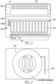
- the thermally conductive component of the PCR compatible film may comprise a wire mesh with a substantially small wire diameter, as shown in FIGURE 3 , thermally conductive particles distributed through the PCR compatible film (in a manner that still allows for optical clarity), or any other appropriate thermally conductive component (e.g. thermally conductive beads integrated into the PCR compatible film).
- the region laterally around the detection chamber may also further include one or more heat-transfer elements or air channels speed heat dissipation.
- a detection chamber 117 in the set of detection chambers 116 may not include a PCR compatible film with a thermally conductive component.
- the thermally insulating material has a low density, which functions to reduce heat transfer from other detection chambers.
- thermal isolation is achieved by geometrically separating or displacing the detection chambers relative to each other within the top layer 110 of the microfluidic cartridge 100, such that heat transfer between detection chambers is hindered.
- each detection chamber 117 in the set of detection chambers 116 is also optically isolated from all other detection chambers, in order to prevent contamination of data from a detection chamber 117 due to light transfer from other detection chambers in the set of detection chambers 116.
- optical isolation is achieved with detection chambers having substantially vertical walls, and separating each detection chamber 117 in the set of detection chambers from each other.
- the sidewalls of each detection chamber 117 in the set of detection chambers 116 are either composed of or surrounded by a material with low autofluorescence and/or poor optical transmission properties to achieve optical isolation.
- each detection chamber 117 are surrounded by an optically opaque material, thus allowing transmission of light to a detection chamber 117 through only the top and bottom regions of the detection chamber 117.
- the microfluidic cartridge 100 may not further comprise any provisions for optical isolation of each detection chamber 117 in the set of detection chambers 116, aside from constructing the set of detection chambers 116 with a material having low autofluorescence.
- an embodiment of the microfluidic cartridge also comprises an intermediate substrate 120, coupled to the top layer 110 and partially separated from the top layer 110 by a film layer 125, configured to form a waste chamber 130.
- the intermediate substrate 120 functions to serve as a substrate to which layers of the microfluidic cartridge may be bonded, to provide guides for the valve pins, and to provide a waste chamber volume into which a waste fluid may be deposited.
- the depth of the intermediate substrate 120 provides a waste chamber volume adequate to accommodate the volume of waste fluids generated within the microfluidic cartridge 100. Additionally, the depth of the intermediate substrate 120 provides a low profile for the microfluidic cartridge 100 to facilitate movement throughout a compact molecular diagnostic system.
- the intermediate substrate 120 of the microfluidic cartridge 100 is coupled to the top layer 110 and partially separated from the top layer 110 by a film layer 125.
- the film layer 125 functions to isolate individual fluidic pathways 165 of the microfluidic cartridge, to prevent leakage, to provide an appropriate environment for sample processing and conducting a molecular diagnostic protocol, and to provide access between a microfluidic channel (of a fluidic pathway 165) above the film layer 125 and elements below the film layer 125 (e.g. waste chamber and/or fluidic pathway occluder).
- the film layer is a polypropylene (PP) with an appropriate glass transition temperature, such that it is PCR compatible and thermally bondable to the top layer 110; however, the film layer may alternatively be any appropriate material.
- the top layer 110, the film layer 125, and the intermediate substrate are bonded together, such that the top layer 110, film layer, 125, and intermediate substrate form a bonded unit with a hermetic seal to prevent fluid leakage.
- a hermetic seal is preferably formed using a silicone rubber layer coupled to the film layer 125, but may alternatively be formed using an alternative material or method.
- a hermetic seal formed using a silicone rubber layer is only required at locations of openings within the film layer (e.g,, at locations where an external occluder interacts with the microfluidic cartridge).
- the top layer 110, the film layer 125, and the intermediate substrate 120 are substantially identical materials (e.g.
- the waste chamber has a volumetric capacity of approximately 25mL; however, the waste chamber 130 of another embodiment may have a different volumetric capacity.
- the intermediate substrate 120 further comprises a waste vent 135, which provides access between a microfluidic channel of a fluidic pathway 165 above the film layer 125 and the waste chamber 130.
- the intermediate substrate 130 comprises more than one waste inlet 136, such that the waste chamber is accessible at more than one location along a fluidic pathway 165 through the waste inlets 136.
- the intermediate substrate 120 may include a single waste inlet 136, such that all waste fluids generated within the microfluidic cartridge 100 are configured to travel through the single waste inlet 136 into the waste chamber 130.
- the intermediate substrate 120 may comprise a waste vent 131, such that the waste chamber 130 is vented to prevent pressure build up in the waste chamber as waste fluid is added.
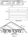
- the waste chamber 130 formed by the intermediate substrate 120 has a corrugated surface 137, such that the waste chamber 130 is not only configured to receive and isolate a waste fluid, but also functions to 1) provide structural stability for the microfluidic cartridge 100 and 2) allow elements external to the microfluidic cartridge 100 to enter spaces formed by the corrugated surface 137, for greater accessibility to elements of the microfluidic cartridge 100.
- each of the ridges in the corrugated surface 137 may not have the same dimensions, as a result of the locations of elements within and external to the microfluidic cartridge 100.
- At least two ridges of the corrugated surface 137 are preferably the same height, such that the microfluidic cartridge 100 sits substantially level on a flat base. In an alternative embodiment, all ridges of the corrugated surface 137 of the waste chamber 130 are identical, for structural symmetry.
- the microfluidic cartridge 100 may further comprise a bottom layer 170 configured to couple to the intermediate substrate, which functions to allow waste to be contained within the microfluidic cartridge 100, and allow microfluidic cartridges to be stacked.
- the bottom layer thus facilitates reception, isolation, and containment of a waste fluid within the waste chamber.
- the bottom layer 170 is composed of the same material as the intermediate substrate 120 for cost and manufacturing considerations, and bonded to the intermediate substrate 120 in a manner that provides a hermetic seal, such that a liquid within the waste chamber 130 does not leak out of the waste chamber 130.
- the bottom layer 170 and the intermediate substrate 120 are both composed of a polypropylene-based material, and bonded together using an adhesive.
- a fluidic pathway 165 is preferably located primarily on the bottom side of the top layer 110, comprising a segment running to a vent region 190 on the top side of the top layer 110. All other segments of the fluidic pathway 165 are preferably located on the bottom side of the top layer 110, allowing the fluidic pathway 165 to be sealed by the film layer 125 without requiring a separate film layer to seal channels located on the top of the top layer 110.
- a fluidic pathway 165 is preferably located primarily on the bottom side of the top layer 110, comprising a segment running to a detection chamber 163 on the top side of the top layer 110 and a segment running away from the detection chamber 164 on the top side of the top layer 110.
- the fluidic pathway 165 thus crosses the thickness of the top layer 110 upstream of the first segment running to the detection chamber 163, and crosses the thickness of the top layer 110 downstream of the segment running away from the detection chamber 164, and crosses the thickness of the top layer 110 to couple to a sample port 114 and a reagent port 115 on the top side of the top layer 110.
- a fluidic pathway 165 is preferably located primarily on the bottom side of the top layer 110, comprising only a segment running away from the detection chamber 164 on the top side of the top layer 110.
- the fluidic pathway 165 thus crosses the thickness of the top layer 110 downstream of the second portion, and crosses the thickness of the top layer 110 to couple to a sample port 114 and a reagent port 115 on the top side of the top layer 110.
- other embodiments may comprise a fluidic pathway 165 with a different configuration of portions on the top side of the top layer 110 and/or portions on the bottom side of the top layer 110.
- a fluidic pathway 165 of the set of fluidic pathways 160 is branched and preferably comprises an initial segment 174 fluidically coupled to a fluid channel 119 coupled to a fluid port 118, a sample segment 175 coupled to a sample port 114, a reagent segment 176 coupled to a reagent port 115, a capture segment 166 passing through at least one of the heating region 195 and a magnetic field 156, a vent segment 177 configured to pass through the vent region 190, a segment running to a detection chamber 163, a segment running away from the detection chamber 164, and at least one waste segment 178, 179 configured to transfer a waste fluid to a waste chamber 130.
- Individual segments of the fluidic pathway 165 are preferably configured to pass through at least one occlusion position of the set of occlusion positions 141, to controllably direct fluid flow through portions of the fluidic pathway 165.
- a fluidic pathway 165 may also further comprise an end vent 199, which functions to prevent any fluid from escaping the microfluidic channel.
- the initial segment 174 of the fluidic pathway 165 functions to deliver common liquids and/or gases from a fluid port 118 through at least a portion of the fluidic pathway 165
- the sample segment 175 functions to deliver a volume of a sample fluid (e.g. sample comprising nucleic acids bound to magnetic beads) to a portion of the fluidic pathway 165
- the reagent segment 176 functions to deliver a volume of fluid comprising a reagent to a portion of the fluidic pathway 165.
- the capture segment 166 functions to facilitate isolation and purification of nucleic acids from the volume of the sample fluid, and may be s-shaped and/or progressively narrowing, to increase the efficiency and/or effectiveness of isolation and purification.
- a first embodiment, as shown in FIGURE 1C , of a fluidic pathway 165 preferably comprises an initial segment 174 fluidically coupled to a fluid channel 119 coupled to a shared fluid port 118, a sample segment 175 coupled to a sample port 114 and to the initial segment 174, and an s-shaped capture segment 166, configured to pass through the heating region 195 and a magnetic field 156, coupled to the initial segment 174 and the sample segment 175.
- the s-shaped capture segment 166 may comprise an initial wide arc 166 to provide a greater surface area for magnetic bead capture.
- the capture segment 166 may alternatively be a progressively narrowing s-shaped capture segment 166.
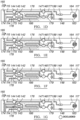
- the occlusion positions of the set of occlusion positions 141' of the second embodiment are preferably located such that occluding of subsets of the set of occlusion positions 141' defines unique truncated fluidic pathways to controllably direct fluid flow.
- An alternative variation of the second embodiment may further comprise additional occlusion positions or alternative variations of the set of occlusion positions 141', such that occlusion at the additional occlusion positions permanently seals the waste chamber from the fluidic pathway 165'.
- Other alternative variations of the second embodiment may also comprise configurations of the set of occlusion positions 141' that are different than that described above.
Landscapes
- Chemical & Material Sciences (AREA)
- Health & Medical Sciences (AREA)
- Life Sciences & Earth Sciences (AREA)
- General Health & Medical Sciences (AREA)
- Chemical Kinetics & Catalysis (AREA)
- Clinical Laboratory Science (AREA)
- Organic Chemistry (AREA)
- Analytical Chemistry (AREA)
- Engineering & Computer Science (AREA)
- Zoology (AREA)
- Wood Science & Technology (AREA)
- Biochemistry (AREA)
- Hematology (AREA)
- Bioinformatics & Cheminformatics (AREA)
- Molecular Biology (AREA)
- Genetics & Genomics (AREA)
- Dispersion Chemistry (AREA)
- Proteomics, Peptides & Aminoacids (AREA)
- Biotechnology (AREA)
- General Engineering & Computer Science (AREA)
- Microbiology (AREA)
- Physics & Mathematics (AREA)
- Biophysics (AREA)
- Biomedical Technology (AREA)
- Immunology (AREA)
- Sustainable Development (AREA)
- Crystallography & Structural Chemistry (AREA)
- Plant Pathology (AREA)
- Fluid Mechanics (AREA)
- Medicinal Chemistry (AREA)
- Apparatus Associated With Microorganisms And Enzymes (AREA)
- Automatic Analysis And Handling Materials Therefor (AREA)
Description
- This invention relates generally to the molecular diagnostics field, and more specifically to an improved microfluidic cartridge for processing and detecting nucleic acids.
- Molecular diagnostics is a laboratory discipline that has developed rapidly during the last 25 years. It originated from basic biochemistry and molecular biology research procedures, but now has become an independent discipline focused on routine analysis of nucleic acids (NA), including deoxyribonucleic acid (DNA) and ribonucleic acid (RNA) for diagnostic use in healthcare and other fields requiring nucleic acid analysis. Molecular diagnostic analysis of biological samples can include the detection and/or monitoring of one or more nucleic acid materials present in the specimen. The particular analysis performed may be either qualitative and/or quantitative. Methods of analysis may involve isolation, purification, and amplification of nucleic acid materials, and polymerase chain reaction (PCR) is a common technique used to amplify nucleic acids. Often, a nucleic acid sample to be analyzed is obtained in insufficient quantity, quality, and/or purity, hindering a robust implementation of a diagnostic technique. Current sample processing methods and molecular diagnostic techniques are also labor/time intensive, low throughput, and expensive, and systems of analysis are insufficient. Examples of prior art include
US2010/165784 andWO2OO7/O64635 -
-
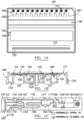
FIGURES 1A-1C depict an embodiment of a microfluidic cartridge (top and side views) and an embodiment of a microfluidic pathway of the microfluidic cartridge; -
FIGURES 1D-K depict an example embodiment of subsets of occlusion positions defining truncated portions of a fluidic pathway; -
FIGURE 2 depicts an alternative embodiment of a microfluidic cartridge (top view) showing individual waste chambers located on the top of cartridge and multiple fluid ports; -
FIGURE 3 depicts an alternative embodiment of a detection chamber of the microfluidic cartridge (top view) and a heating element configured to heat the detection chamber; -
FIGURE 4 depicts an embodiment of a waste chamber of the microfluidic cartridge; -
FIGURES 5A-5D depict embodiments of the elastomeric layer of the microfluidic cartridge, in open and occluded configurations; -
FIGURES 6A-6C depict a microfluidic cartridge (top and side views) which does not form part of the invention and an alternative embodiment of a microfluidic pathway of the microfluidic cartridge; -
FIGURE 7 depicts another alternative embodiment of a microfluidic pathway of the microfluidic cartridge; -
FIGURES 8A and 8B depict schematics of microfluidic channel cross sections; -
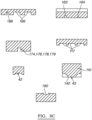
FIGURE 8C depicts specific embodiments of microfluidic channel cross sections; -
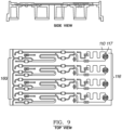
FIGURE 9 depicts an embodiment of the microfluidic cartridge with twelve fluidic pathways (four of which are shown); -
FIGURES 10A and 10B depict embodiments of occlusion of fluidic pathways with the elastomeric layer and a valving mechanism; -
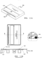
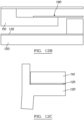
FIGURES 11A and 11B depict an embodiment of the microfluidic cartridge; -
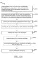
FIGURES 12A-12G depict an example manufacturing method for an embodiment of the microfluidic cartridge; and -
FIGURE 13 depicts an alternative example manufacturing method for an embodiment of the microfluidic cartridge. - The present invention is defined by the features of claim 1. Further developments and further features are defined by the dependent claims.
- As shown in
FIGURES 1A-1C , an embodiment of amicrofluidic cartridge 100 for processing and detecting nucleic acids comprises: atop layer 110 comprising a set of sample port-reagent port pairs 112 and a set ofdetection chambers 116; anintermediate substrate 120, coupled to thetop layer 110 and partially separated from the top layer by afilm layer 125, configured to form awaste chamber 130; anelastomeric layer 140 partially situated on theintermediate substrate 120; amagnet housing region 150 accessible by amagnet 152 providing a magnetic field 156; and a set offluidic pathways 160, each formed by at least a portion of thetop layer 110, a portion of thefilm layer 125, and a portion of theelastomeric layer 140. In other embodiments, themicrofluidic cartridge 100 may further comprise abottom layer 170 coupled to theintermediate substrate 120 and configured to seal thewaste chamber 130. Furthermore, thetop layer 110 of themicrofluidic cartridge 100 further comprises afluid port 118, in particular a sharedfluid port 118. Thetop layer 110 of themicrofluidic cartridge 100 may further comprise avent region 190, and aheating region 195, such that eachfluidic pathway 165 in the set offluidic pathways 160 is fluidically coupled to a sample port-reagent port pair 113, theshared fluid port 118, thewaste chamber 130, and adetection chamber 117, comprises acapture segment 166 configured to pass through the heating region and the magnetic field, and is configured to pass through thevent region 190 upstream of thedetection chamber 117. Eachfluidic pathway 165 thus functions to receive and facilitate processing of a sample fluid containing nucleic acids as it passes through different portions of thefluidic pathway 165. As configured, themicrofluidic cartridge 100 can be used to facilitate molecular diagnostic processes and techniques, and preferably conforms to microtiter plate dimensional standards. Alternatively, themicrofluidic cartridge 100 may be any appropriate size. In a specific application, themicrofluidic cartridge 100 can be used to facilitate a PCR procedure for analysis of a sample containing nucleic acids. - The
top layer 110 of an embodiment of themicrofluidic cartridge 100 functions to accommodate elements involved in performing a molecular diagnostic procedure (e.g. PCR), such that a sample containing nucleic acids, passing through the cartridge, can be manipulated by the elements involved in performing the molecular diagnostic procedure. Thetop layer 110 is preferably composed of a structurally rigid /stiff material with low autofluorescence, such that thetop layer 110 does not interfere with sample detection by fluorescence or chemiluminescence techniques, and an appropriate glass transition temperature and chemical compatibility for PCR or other amplification techniques. Preferably, thetop layer 110 is composed of a polypropylene-based polymer, but thetop layer 110 may alternatively be composed of any appropriate material (e.g. cyclic olefin polymer). In a specific embodiment, thetop layer 110 is composed of 1.5mm thick polypropylene produced by injection molding, with a glass transition temperature between 136 and 163°C. Thetop layer 110 may alternatively be composed of any appropriate material, for example, a polypropylene based polymer. As shown inFIGURES 1B and 1C , thetop layer 110 preferably comprises a set of sample port-reagent port pairs 112, afluid port 118, avent region 190, aheating region 195 crossing acapture segment 166 of afluidic pathway 165, and a set ofdetection chambers 116. - Each sample-port-
reagent port pair 113 of an embodiment of thetop layer 110 comprises asample port 114 and areagent port 115. Thesample port 114 functions to receive a volume of a sample fluid potentially containing the nucleic acids of interest for delivery of the volume of fluid to a portion of afluidic pathway 165 coupled to the sample port-reagent port pair 113. In a specific embodiment, the volume of a sample fluid is a biological sample with magnetic beads for nucleic acid isolation; however, the volume of fluid comprising a sample fluid may alternatively be any appropriate fluid containing a sample with nucleic acids. Preferably, eachsample port 114 is isolated from all other sample ports, in order to prevent cross-contamination between samples of nucleic acids being analyzed. Additionally, eachsample port 114 is preferably of an appropriate geometric size and shape to accommodate a standard-size pipette tip used to deliver the volume of a sample fluid without leaking. Alternatively, all or a portion of thesample ports 114 are configured to be coupled to fluid conduits or tubing that deliver the volume of a sample fluid. - Each sample-port
reagent port pair 113 of an embodiment of thetop layer 110 also comprises areagent port 115, as shown inFIGURE 1A . Thereagent port 115 in a sample port-reagent port pair 113 functions to receive a volume of fluid comprising a reagent used in molecular diagnostics, for delivery of the volume of fluid comprising a reagent to a portion of afluidic pathway 165 coupled to the sample port-reagent port pair 113. In a specific embodiment, the volume of fluid comprising a reagent used in molecular diagnostics is a sample of reconstituted molecular diagnostic reagents mixed with nucleic acids released and isolated using themicrofluidic cartridge 100; however, the volume of fluid comprising a reagent used in molecular diagnostics may alternatively be any appropriate fluid comprising reagents used in molecular diagnostics. Preferably, eachreagent port 115 is isolated from all other reagent ports, in order to prevent cross-contamination between samples of nucleic acids being analyzed. Additionally, eachreagent port 115 is preferably of an appropriate geometric size to accommodate a standard-size pipette tip used to deliver the volume of fluid comprising a reagent used in molecular diagnostics. Alternatively, all or a portion of thereagent ports 115 are configured to be coupled to fluid conduits or tubing that deliver the volume of fluid comprising a reagent used in molecular diagnostics. - Preferably, the set of sample port-
reagent port pairs 112 is located near a first edge of thetop layer 110, such that the configuration of the sample port-reagent port pairs 112 functions to increase accessibility, for instance, by a pipettor delivering fluids to themicrofluidic cartridge 100. In one specific example, themicrofluidic cartridge 100 is configured to be aligned within a module, with the set of sample port-reagent port pairs 112 accessible outside of the module, such that a multichannel pipette head can easily access the set of sample port-reagent port pairs 112. Preferably, as shown inFIGURE 1A , the set of sample port-reagent port pairs 112 is configured such that thesample ports 114 and thereagent ports 115 alternate along the first edge of thetop layer 110. In an alternative embodiment, the set of sample port-reagent port pairs 112 may not be located near an edge of thetop layer 110, and may further not be arranged in an alternating fashion. - The
fluid port 118 of thetop layer 110 of the microfluidic cartridge functions to receive at least one of a wash fluid, a release fluid, and a gas used in a molecular diagnostic procedure, such as PCR. In an embodiment, the wash fluid, the release fluid, and/or the gas are common to all samples being analyzed during a run of the diagnostic procedure using themicrofluidic cartridge 100; in this embodiment, as shown inFIGURE 1A , thefluid port 118 is preferably a shared fluid port, fluidically coupled to allfluidic pathways 165 coupled to the sample port-reagent port pairs 112, and configured to deliver the same wash fluid, release fluid, and/or gas through the shared fluid port. Alternatively, as shown inFIGURE 2 , the top layer may comprise more than onefluid port 118, configured to deliver different wash fluids, release fluids, and/or gases to individual or multiplefluidic pathways 165 coupled to the set of sample port-reagent port pairs 112. - Preferably, the
fluid port 118 is located along an edge of themicrofluidic cartridge 100, which functions to increase accessibility to the fluid port by a system delivering fluids to thefluid port 118. In a specific embodiment, as shown inFIGURE 1A , the fluid port is located approximately midway along an edge of themicrofluidic cartridge 100, different from the edge along which the set of sample port-reagent port pairs 112 is located. Alternatively, thefluid port 118 may not be located along an edge of themicrofluidic cartridge 100. Additionally, thefluid port 118 is preferably configured to be coupled to a syringe pump for fluid delivery; however, thefluid port 118 may alternatively configured to couple to any appropriate system for fluid delivery. Preferably, the wash fluid is a wash buffer for washing bound nucleic acid samples (i.e. nucleic acids bound to magnetic beads), the release fluid is a reagent for releasing bound nucleic acids samples from the magnetic beads, and the gas is pressurized air for moving fluids and demarcating separate reagents. Alternatively, the wash fluid, release fluid, and gas may be any appropriate liquids or gases used to carry out a molecular diagnostic procedure. - The
heating region 195 of thetop layer 110 functions to accommodate and position a heating element relative to elements of themicrofluidic cartridge 100. The heating element preferably heats a defined volume of fluid and the magnetic beads, which has traveled through themicrofluidic cartridge 100, according to a specific molecular diagnostic procedure protocol (e.g. PCR protocol), and is preferably an element external to themicrofluidic cartridge 100; alternatively, the heating element may be integrated with the microfluidic cartridge and/or comprise a thermally conductive element integrated into themicrofluidic cartridge 100. Theheating region 195 is preferably a recessed fixed region of thetop layer 110, downstream of the sample port-reagent port pairs 112, as shown inFIGURES 1A and 1B . Alternatively, the heating region may not be fixed and/or recessed, such that theheating region 195 sweeps across thetop layer 110 of themicrofluidic cartridge 100 as the heating element is moved. Themicrofluidic cartridge 100 may altogether omit theheating region 195 of the top layer no, in alternative embodiments using alternative processes (e.g. chemical methods) for releasing nucleic acids from nucleic acid-bound magnetic beads. - The
vent region 190 of an embodiment of thetop layer 110 functions to remove unwanted gases trapped within afluidic pathway 165 of the microfluidic cartridge, and may additionally function to position a defined volume of fluid within afluidic pathway 165 of the microfluidic cartridge. Thevent region 190 is preferably located downstream of theheating region 195 in an embodiment where theheating region 195 is fixed on thetop layer 110 of themicrofluidic cartridge 100, but alternatively may be located at another appropriate position on thetop layer 110 such that unwanted gases are substantially removed from themicrofluidic cartridge 100 during analysis. Thetop layer 110 may alternatively comprise more than onevent region 190 located at appropriate positions in thetop layer 110. Preferably, as shown inFIGURES 1A and 1B , thevent region 190 is a recessed region in thetop layer 110, and further comprises a film covering thevent region 190. Preferably, the film covering thevent region 190 is a gas-permeable but liquid-impermeable film, such that unwanted gases may be released from themicrofluidic cartridge 100, but fluids remain within themicrofluidic cartridge 100 and flow to the point of contacting the film. This functions to remove unwanted gases and position a defined volume of fluid within afluidic pathway 165 of the microfluidic cartridge. In a specific embodiment, the film covering the vent region is a hydrophobic porous polytetrafluoroethylene-based material, synthesized to be gas-permeable but liquid-impermeable. Alternatively, the film covering the vent region may be gas and liquid permeable, such that unwanted gases and liquids are expelled from themicrofluidic cartridge 100 through thevent region 190. Other alternative embodiments of themicrofluidic cartridge 100 may altogether omit the vent region. - The set of
detection chambers 116 of an embodiment of thetop layer 110 functions to receive a processed nucleic acid sample, mixed with molecular diagnostic reagents, for molecular diagnostic analysis. Preferably, the set ofdetection chambers 116 is located along an edge of thetop layer 110, opposite the edge along which the set of sample port-reagent port pairs 112 is located, which allows sample fluids dispensed into themicrofluidic cartridge 100 to be processed and mixed with molecular diagnostic reagents on their way to adetection chamber 117 of the set ofdetection chambers 116 and facilitates access to the detection chambers by external elements performing portions of a molecular diagnostics protocol (e.g. heating and optics systems). Alternatively, the set ofdetection chambers 116 may not be located along an edge of the top layer no. In a first variation, as shown inFIGURES 1A and11B , eachdetection chamber 117 in the set of detection chambers comprises a serpentine-shaped channel 16 for facilitating analysis of a solution of nucleic acids mixed with reagents. In the first variation, three portions of the serpentine-shaped channel 16 are preferably wide and shallow to facilitate heating, and are interconnected by two narrow portions, which function to increase fluid flow resistance and reduce the proportion of nucleic acid not contained within the detection area. The first variation functions to facilitate filling of the set of detection chambers in a manner that reduces the potential for trapped air bubbles, to facilitate rapid molecular diagnostic techniques, and to comply with current imaging technologies. In a specific example of the first variation, each serpentine-shaped channel 16 is injected molded into thetop layer 110 of themicrofluidic cartridge 100, and the three interconnected portions of the serpentine-shaped channel 16 are each 1600 µm wide by 400µm deep. - In a second variation, each
detection chamber 117 in the set of detection chambers has a depth between 0.400mm and 1.00mm, and a diameter between 3.50mm and 5.70mm, to provide a volumetric configuration that facilitates reaction efficiency. In a specific example of the second variation, eachdetection chamber 117 in the set ofdetection chambers 116 is configured to contain a total volume of 10uL, and has a depth of o.8omm and a diameter of 3.99mm; however, in alternative embodiments, eachdetection chamber 117 in the set ofdetection chambers 116 may be configured to contain a total volume less than or greater than 10uL. - Preferably, as shown in
FIGURES 1A and 1B , the lower regions of eachdetection chamber 117 in the set ofdetection chambers 116 includes a PCR compatible film that is thin, to facilitate efficient thermocycling, and has low autofluorescence, to facilitate light-based molecular diagnostic assays performed at the set ofdetection chambers 116. The PCR compatible film is preferably composed of a polypropylene based polymer thermally bonded to the bottom of the top layer, but may alternatively be composed of any appropriate PCR-compatible material and bonded in any fashion. In one specific variation, the PCR compatible film is a cyclic olefin polymer (COP) film, thermally bonded to thetop layer 110, with a glass transition temperature suitable for a molecular diagnostic protocol. In one alternative embodiment, depending on the configuration of imaging, heating, and/or cooling elements external to themicrofluidic cartridge 100, the top and/or bottom of thedetection chambers 117 in the set ofdetection chambers 116 may be entirely formed of a clear or transparent material (e.g. glass or plastic) allowing transmission of light. In a variation of this alternative embodiment, lensing, other optical components, or additional structures may also be incorporated into the detection chambers, to facilitate light transmission and/or focusing. In the variation of the alternative embodiment, a lens may be manufactured (e.g. injection molded) directly to form a surface of adetection chamber 117. - In the embodiment of the set of
detection chambers 116 that includes a PCR compatible film, the PCR compatible film may further include a thermally conductive component, which functions to transfer heat from a heating element to the detection chamber. Depending on the position of the heating element(s) relative to themicrofluidic cartridge 100 during analysis, the thermally conductive component of the PCR compatible film may be integrated with just the upper region of each detection chamber, just the lower region of each detection chamber, or both the upper and lower regions of each Detection chamber. The thermally conductive component of the PCR compatible film may comprise a wire mesh with a substantially small wire diameter, as shown inFIGURE 3 , thermally conductive particles distributed through the PCR compatible film (in a manner that still allows for optical clarity), or any other appropriate thermally conductive component (e.g. thermally conductive beads integrated into the PCR compatible film). The region laterally around the detection chamber may also further include one or more heat-transfer elements or air channels speed heat dissipation. Alternatively, adetection chamber 117 in the set ofdetection chambers 116 may not include a PCR compatible film with a thermally conductive component. Preferably, eachdetection chamber 117 is heated using a diced silicon wafer with conductive channels flip-chip bonded to a detection chamber to provide resistive heating; however, eachdetection chamber 117 may alternatively be heated using any appropriate heating device or method, and may be assembled using any appropriate method. - Preferably, each
detection chamber 117 in the set ofdetection chambers 116 is thermally isolated from all other detection chambers, in order to prevent contamination of data from adetection chamber 117 due to heat transfer from other detection chambers in the set ofdetection chambers 116. In one embodiment, eachdetection chamber 117 of the set ofdetection chambers 116 is spaced far from adjacent detection chambers to limit thermal crosstalk. In another alternative embodiment, thetop layer 110 may comprises slots between adjacent detection chambers to separate the detection chambers with an air gap. In one variation, thermal isolation is achieved by surrounding the side walls of eachdetection chamber 117 with a thermally insulating material, such as an insulating epoxy, putty, filler, or sealant. In another variation, the thermally insulating material has a low density, which functions to reduce heat transfer from other detection chambers. In yet another variation, thermal isolation is achieved by geometrically separating or displacing the detection chambers relative to each other within thetop layer 110 of themicrofluidic cartridge 100, such that heat transfer between detection chambers is hindered. - Preferably, each
detection chamber 117 in the set ofdetection chambers 116 is also optically isolated from all other detection chambers, in order to prevent contamination of data from adetection chamber 117 due to light transfer from other detection chambers in the set ofdetection chambers 116. Preferably, optical isolation is achieved with detection chambers having substantially vertical walls, and separating eachdetection chamber 117 in the set of detection chambers from each other. However, in one variation, the sidewalls of eachdetection chamber 117 in the set ofdetection chambers 116 are either composed of or surrounded by a material with low autofluorescence and/or poor optical transmission properties to achieve optical isolation. In another variation, the sidewalls of eachdetection chamber 117 are surrounded by an optically opaque material, thus allowing transmission of light to adetection chamber 117 through only the top and bottom regions of thedetection chamber 117. Alternatively, themicrofluidic cartridge 100 may not further comprise any provisions for optical isolation of eachdetection chamber 117 in the set ofdetection chambers 116, aside from constructing the set ofdetection chambers 116 with a material having low autofluorescence. - Additionally, each
detection chamber 117 in the set ofdetection chambers 116 may be further optimized to meet volumetric capacity requirements, facilitate high thermocycling rates, facilitate optical detection, and facilitate filling in a manner that limits bubble generation. Alternatively eachdetection chamber 117 in the set ofdetection chambers 116 may not be optimized to meet volumetric capacity requirements, facilitate high thermocycling rates, facilitate optical detection, and/or facilitate filling in a manner that limits bubble generation. - The
top layer 110 of themicrofluidic cartridge 100 may further comprise a set of cartridge-aligningindentations 180, which function to align themicrofluidic cartridge 100 as it moves through an external module. As shown inFIGURE 2 the set of cartridge-aligningindentations 180 are preferably located such that they do not interfere with anyports vent region 190, and/or the set ofdetection chambers 116. In an embodiment, thetop layer 110 of the microfluidic cartridge preferably comprises at least four cartridge-aligning indentations, located at points on the periphery of thetop layer 110, and the cartridge-aligning indentations are configured to be recessed regions configured to mate with alignment pins in a system external to themicrofluidic cartridge 100. Alternatively, the cartridge-aligning indentations may be grooves, such that themicrofluidic cartridge 100 accurately slides into position along the grooves within a system external to themicrofluidic cartridge 100. In yet another alternative embodiment, the set of cartridge-aligningindentations 180 may be any appropriate indentations that allow for positioning of themicrofluidic cartridge 100 within an external system. However, themicrofluidic cartridge 100 may altogether omit the set of cartridge-aligningindentations 180, and rely upon other features of themicrofluidic cartridge 100 to facilitate alignment. - As shown in
FIGURE 1B , an embodiment of the microfluidic cartridge also comprises anintermediate substrate 120, coupled to thetop layer 110 and partially separated from thetop layer 110 by afilm layer 125, configured to form awaste chamber 130. Theintermediate substrate 120 functions to serve as a substrate to which layers of the microfluidic cartridge may be bonded, to provide guides for the valve pins, and to provide a waste chamber volume into which a waste fluid may be deposited. Preferably, the depth of theintermediate substrate 120 provides a waste chamber volume adequate to accommodate the volume of waste fluids generated within themicrofluidic cartridge 100. Additionally, the depth of theintermediate substrate 120 provides a low profile for themicrofluidic cartridge 100 to facilitate movement throughout a compact molecular diagnostic system. Preferably, theintermediate substrate 120 of themicrofluidic cartridge 100 is also configured such that the footprint ofmicrofluidic cartridge 100 adheres to microtiter plate standards, to facilitate automated handling of themicrofluidic cartridge 100. Theintermediate substrate 120 is preferably composed of a low-cost, structurally stiff material, such as polypropylene. However, similar to thetop layer 120, the intermediate substrate may be alternatively composed of a structurally stiff material with low autofluorescence, such that theintermediate substrate 120 does not interfere with sample detection by fluorescence techniques, and an appropriate glass transition temperature for PCR techniques. In one variation of this alternative embodiment, theintermediate substrate 120 is composed of a cyclic olefin polymer (COP), produced by injection molding, with a glass transition temperature between 136 and 163°C. In yet another alternative embodiment, theintermediate substrate 120 may be composed of any appropriate material, for example, a polycarbonate based polymer. - Preferably, the
intermediate substrate 120 of themicrofluidic cartridge 100 is coupled to thetop layer 110 and partially separated from thetop layer 110 by afilm layer 125. Thefilm layer 125 functions to isolate individualfluidic pathways 165 of the microfluidic cartridge, to prevent leakage, to provide an appropriate environment for sample processing and conducting a molecular diagnostic protocol, and to provide access between a microfluidic channel (of a fluidic pathway 165) above thefilm layer 125 and elements below the film layer 125 (e.g. waste chamber and/or fluidic pathway occluder). Preferably, the film layer is a polypropylene (PP) with an appropriate glass transition temperature, such that it is PCR compatible and thermally bondable to thetop layer 110; however, the film layer may alternatively be any appropriate material. In a specific embodiment, thefilm layer 125 is a polypropylene film between 30 and 100 microns thick and die cut to produce openings at a set of occlusion positions, to provide access between a microfluidic channel of afluidic pathway 165 above thefilm layer 125 and elements below thefilm layer 125. In this specific embodiment, the openings are slightly oversized prior to assembly, in order to allow for constriction during assembly (due to thermal and pressure effects) and to provide higher tolerance during assembly of microfluidic cartridge layers. Alternatively, the film layer is any appropriate material such that it substantially isolates individual fluidic pathways, and is easily processable to provide access between a microfluidic channel of afluidic pathway 165 above the film layer and elements below thefilm layer 125. - Preferably, the
top layer 110, thefilm layer 125, and the intermediate substrate are bonded together, such that thetop layer 110, film layer, 125, and intermediate substrate form a bonded unit with a hermetic seal to prevent fluid leakage. A hermetic seal is preferably formed using a silicone rubber layer coupled to thefilm layer 125, but may alternatively be formed using an alternative material or method. In a specific embodiment, a hermetic seal formed using a silicone rubber layer is only required at locations of openings within the film layer (e.g,, at locations where an external occluder interacts with the microfluidic cartridge). Preferably, in an embodiment where thetop layer 110, thefilm layer 125, and theintermediate substrate 120 are substantially identical materials (e.g. polypropylene), at least one of thermal bonding, adhesives, and ultrasonic welding are used to coupled thelayers top layer 110, thefilm layer 125, and theintermediate substrate 120 are substantially different materials - a combination of thermal bonding methods and adhesives may be used to bond thetop layer 110, thefilm layer 125, and theintermediate substrate 120 of themicrofluidic cartridge 100 together. In an alternative embodiment, thetop layer 110, thefilm layer 125, and theintermediate substrate 120 of themicrofluidic cartridge 100 may be thermally bonded together in a single step. In yet another alternative embodiment, thetop layer 110, thefilm layer 125, and theintermediate substrate 120 may alternatively be modular, in applications where a portion of themicrofluidic cartridge 100 is partially reusable (e.g. in an application where the waste chamber may be discarded after use, but the top layer and film may be reused). In yet another alternative embodiment, thetop layer 110, thefilm layer 125, and theintermediate substrate 120 may only be partially bonded, such that a molecular diagnostic system, into which themicrofluidic cartridge 100 is loaded, is configured to compress thetop layer 110, thefilm layer 125, and theintermediate substrate 120 together, preventing any fluid leakage. - As shown in
FIGURE 1B , theintermediate substrate 120 of themicrofluidic cartridge 100 of the invention is configured to form awaste chamber 130, which functions to receive and isolate waste fluids generated within themicrofluidic cartridge 100. Thewaste chamber 130 is preferably continuous and accessible by eachfluidic pathway 165 of themicrofluidic cartridge 100, such that all waste fluids generated within themicrofluidic cartridge 100 are deposited into a common waste chamber; however, eachfluidic pathway 165 of themicrofluidic cartridge 100 may alternatively have its owncorresponding waste chamber 130, such that waste fluids generated within afluidic pathway 165 of themicrofluidic cartridge 100 are isolated from waste fluids generated within otherfluidic pathways 165 of themicrofluidic cartridge 100. In a specific embodiment of themicrofluidic cartridge 100 with a continuous waste chamber, the waste chamber has a volumetric capacity of approximately 25mL; however, thewaste chamber 130 of another embodiment may have a different volumetric capacity. Theintermediate substrate 120 further comprises awaste vent 135, which provides access between a microfluidic channel of afluidic pathway 165 above thefilm layer 125 and thewaste chamber 130. Preferably, theintermediate substrate 130 comprises more than onewaste inlet 136, such that the waste chamber is accessible at more than one location along afluidic pathway 165 through thewaste inlets 136. Alternatively, theintermediate substrate 120 may include asingle waste inlet 136, such that all waste fluids generated within themicrofluidic cartridge 100 are configured to travel through thesingle waste inlet 136 into thewaste chamber 130. Also, as shown inFIGURE 1B , theintermediate substrate 120 may comprise awaste vent 131, such that thewaste chamber 130 is vented to prevent pressure build up in the waste chamber as waste fluid is added. - As shown in
FIGURES 1B and4 , thewaste chamber 130 formed by theintermediate substrate 120 has acorrugated surface 137, such that thewaste chamber 130 is not only configured to receive and isolate a waste fluid, but also functions to 1) provide structural stability for themicrofluidic cartridge 100 and 2) allow elements external to themicrofluidic cartridge 100 to enter spaces formed by thecorrugated surface 137, for greater accessibility to elements of themicrofluidic cartridge 100. Also shown inFIGURES 1B and4 , each of the ridges in thecorrugated surface 137 may not have the same dimensions, as a result of the locations of elements within and external to themicrofluidic cartridge 100. At least two ridges of thecorrugated surface 137 are preferably the same height, such that themicrofluidic cartridge 100 sits substantially level on a flat base. In an alternative embodiment, all ridges of thecorrugated surface 137 of thewaste chamber 130 are identical, for structural symmetry. - In one preferred embodiment, the
intermediate substrate 120 of themicrofluidic cartridge 100 further comprises a set of valve guides, which function to direct a series of external pins or other indenters through the valve guides at a set ofocclusion positions 141, thus affecting flow through a microfluidic channel of afluidic pathway 165 at the set of occlusion positions 141. The set of valve guides 127 may also function to facilitate alignment of themicrofluidic cartridge 100 within an external molecular diagnostic module. In a first embodiment, as shown inFIGURE 1B , the set of valve guides 127 comprises holes within theintermediate substrate 120 at the set ofocclusion positions 141, with sloped edges configured to direct a pin or indenter through the holes. In the first embodiment, the set of valve guides 127 may be produced in theintermediate substrate 120 by injection molding, or may alternatively be produced by drilling, countersinking, chamfering, and/or beveling. In another embodiment, the set of valve guides 127 comprises grooves with holes, such that a pin or indenter is configured to travel along a groove and through a hole that defines the valve guide. In a simplified alternative variation, the set of valve guides 127 may comprise holes through theintermediate substrate 120, wherein the holes do not have sloped edges. In yet another simplified alternative variation, the set of valve guides 127 may comprise a slot configured to provide access to theelastomeric layer 140 by a group of occluding objects (e.g. pins or indenters), rather than a single occluding object. - As shown in
FIGURE 1B and5A-5D , themicrofluidic cartridge 100 of the invention also comprises anelastomeric layer 140 partially situated on theintermediate substrate 120, which functions to provide a deformable substrate that, upon deformation, occludes a microfluidic channel of afluidic pathway 165 contacting theelastomeric layer 140 at an occlusion position of a set of occlusion positions 141. Preferably, theelastomeric layer 140 comprises an inert, liquid impermeable material, of an appropriate thickness, that can be heated to temperatures encountered during manufacturing and/or specified in a molecular diagnostic protocol, without substantial damage (i.e. compromised surface and/or loss of mechanical robustness) and is chemically compatible with a PCR assay. Preferably, theelastomeric layer 140 is non-continuous, such that portions of theelastomeric layer 140 are positioned relative to theintermediate substrate 120 in a manner that directly covers holes provided by the set of valve guides 127. Alternatively, theelastomeric layer 140 is a continuous layer, spanning a majority of the footprint of themicrofluidic cartridge 100 while covering holes provided by the set of valve guides 127. In a specific embodiment, theelastomeric layer 140 comprises 500 micron thick strips of a low-durometer silicone that can be heated to at least 120°C without substantial damage, which are bonded to a portion of theintermediate substrate 120 using a silicone-based adhesive and slightly compressed between thefilm layer 125 and theintermediate substrate 120. In a variation of the specific embodiment, theelastomeric layer 140 may alternatively be held in place solely by pressure between theintermediate layer 120 and thetop layer 110. Preferably, theelastomeric layer 140 is reversibly deformable over the usage lifetime of themicrofluidic cartridge 100, such that any occlusion of a microfluidic channel of afluidic pathway 165 contacting theelastomeric layer 140 is reversible over the usage lifetime of the microfluidic cartridge. Alternatively, theelastomeric layer 140 may not be reversibly deformable, such that an occlusion of a microfluidic channel of afluidic pathway 165 contacting theelastomeric layer 140 is not reversible. - The set of
occlusion positions 141 preferably comprises at least two types of occlusion positions, as shown inFIGURE 1C , including a normallyopen position 42 and a normally closedposition 43. As shown inFIGURES 5A-5D , theelastomeric layer 140 at a normallyopen position 42 of the set ofocclusion positions 141 may be closed upon occlusion by an occluding object (FIGURES 5B and 5D ). Preferably, a normallyopen position 42 is configured to withstand pressures that can be generated by a fluid delivery system (e.g. a syringe pump) without leaking, upon occlusion by an occluding object at the normallyopen position 42. In one specific example, a ½ barrel-shaped pin head may be used to fully occlude a normallyopen position 42 having an arched cross section, as inFIGURE 5C , with near constant pressure on the portion of the elastomeric layer compressed between the occluding object and occluding position. - The normally closed
position 43 of the set ofocclusion positions 141, functions to be normally closed, but to be forced open in response to fluid delivery by a fluid delivery system. In one variation, the normally closedposition 43 may be formed by manufacturing (e.g. injection molding) thetop layer 100, such that the top layer material at a normally closedposition 43 extends down to theelastomeric layer 140. If an occluding object is held away from the normally closedposition 43, the occlusion position is closed, but can be forced open due to fluid pressure applied by a fluid delivery system (e.g. syringe pump). When not in operation, however, the normally closedposition 43 is configured to prevent leakage and/or fluid bypass. The normally closed position may also be held closed by an occluding object, to prevent leakage even under pressure provided by a fluid delivery system, or under pressure experienced during a high temperature step (e.g., thermocycling) to prevent evaporation of a sample undergoing thermocycling. - The
microfluidic cartridge 100 may further comprise abottom layer 170 configured to couple to the intermediate substrate, which functions to allow waste to be contained within themicrofluidic cartridge 100, and allow microfluidic cartridges to be stacked. The bottom layer thus facilitates reception, isolation, and containment of a waste fluid within the waste chamber. Preferably, thebottom layer 170 is composed of the same material as theintermediate substrate 120 for cost and manufacturing considerations, and bonded to theintermediate substrate 120 in a manner that provides a hermetic seal, such that a liquid within thewaste chamber 130 does not leak out of thewaste chamber 130. In a specific embodiment, thebottom layer 170 and theintermediate substrate 120 are both composed of a polypropylene-based material, and bonded together using an adhesive. Thebottom layer 170 preferably only seals voids defining thewaste chamber 130, such that non-waste chamber regions (i.e. non-waste housing regions) are not covered by thebottom layer 170. Alternatively, themicrofluidic cartridge 100 may omit thebottom layer 170, such that any waste fluid that enters thewaste chamber 130 completely leaves themicrofluidic cartridge 100 and is collected off-cartridge by a waste-collecting subsystem of an external molecular diagnostic system. In this alternative embodiment, theintermediate substrate 120 is configured to fluidically couple to the waste-collecting subsystem. - The
magnet housing region 150 of themicrofluidic cartridge 100 functions to provide access to and/or house at least onemagnet 152 providing a magnetic field 156 for purification and isolation of nucleic acids. Preferably, themagnet housing region 150 is defined by the film layer and the intermediate substrate, such that the film layer and the intermediate substrate form the boundaries of themagnet housing region 150. In an embodiment of themicrofluidic cartridge 100 comprising abottom layer 170, themagnet housing region 150 may further be defined by thebottom layer 170, such that the bottom layer partially forms a boundary of themagnet housing region 150. Themagnet housing region 150 is preferably a rectangular prism-shaped void in themicrofluidic cartridge 150, and accessible only through one side of themicrofluidic cartridge 100, as shown inFIGURE 1B . Preferably, themagnet housing region 150 can be reversibly passed over amagnet 152 to house themagnet 152, and retracted to remove themagnet 152 from themagnet housing region 150; however, themagnet 152 may alternatively be irreversibly fixed within themagnet housing region 150 once themagnet 152 enters themagnet housing region 150. - Preferably, the
magnet housing region 150 is bounded on at least two sides by thewaste chamber 130, and positioned near the middle of themicrofluidic cartridge 100, such that afluidic pathway 165 passing through the magnetic field 156 passes through the magnetic field 156 at least at one point along an intermediate portion of thefluidic pathway 165. Preferably, themagnet housing region 150 also substantially spans at least one dimension of the microfluidic cartridge, such that multiplefluidic pathways 165 of themicrofluidic cartridge 100 cross the samemagnet housing region 150,magnet 152, and/or magnetic field 156. Alternatively, themagnet housing region 150 may be configured such that a magnet within themagnet housing region 150 provides a magnetic field spanning allfluidic pathways 165 of the microfluidic cartridge in their entirety. In alternative embodiments, the microfluidic cartridge may comprise more than onemagnet housing region 150, amagnet housing region 150 may be configured to receive and/or house more than onemagnet 152, and/or may not be positioned near the middle of themicrofluidic cartridge 100. In yet another alternative embodiment, themagnet housing region 150 may permanently house amagnet 152, such that microfluidic cartridge comprises amagnet 152, integrated with theintermediate substrate 120. In embodiments where themagnet 152 is retractable from themicrofluidic cartridge 100, themagnet 152 may be a permanent magnet or an electromagnet. In embodiments where themagnet 152 is configured to be integrated with themicrofluidic cartridge 100, themagnet 152 is preferably a permanent magnet, which provides a stronger magnetic field per unit volume. - The set of
fluidic pathways 160 of themicrofluidic cartridge 100 functions to provide a fluid network into which volumes of sample fluids, reagents, buffers and/or gases used in a molecular diagnostics protocol may be delivered, out of which waste fluids may be eliminated, and by which processed nucleic acid samples may be delivered to a detection chamber for analysis, which may include amplification and/or detection. Preferably, eachfluidic pathway 165 in the set offluidic pathways 160 is formed by at least a portion of the top layer, a portion of the film layer, and a portion of theelastomeric layer 140, such that eachfluidic pathway 165 may be occluded upon deformation of theelastomeric layer 140 at a set of occlusion positions 141. Additionally, at least onefluidic pathway 165 in the set offluidic pathways 160 is preferably fluidically coupled to a sample port-reagent port pair 113 of the set of sample port-reagent port pairs 112, afluid port 118, awaste chamber 130, and adetection chamber 117 of the set ofdetection chambers 116. Furthermore, at least onefluidic pathway 165 in the set offluidic pathways 160 is preferably configured to be occluded upon deformation of theelastomeric layer 140, configured to transfer a waste fluid to the waste chamber 30, comprises acapture segment 166 passing through theheating region 195 and a magnetic field 156, and is configured to pass through thevent region 190 upstream of adetection chamber 117. Alternative embodiments may omit preferred elements of the embodiment of thefluidic pathway 165 described above, such as avent region 190 or aheating region 195, or add additional elements to the embodiment of thefluidic pathway 165 described above. - A
fluidic pathway 165 of the set offluidic pathways 160 may comprise portions (i.e. microfluidic channels) that are located on both sides of thetop layer 110, but is preferably located primarily on the bottom side of the top layer (in the orientation shown inFIGURE 1B ). In the orientation of themicrofluidic cartridge 100 shown inFIGURE 1B , a microfluidic channel on top of thetop layer 110 may be further covered by second film layer 168 that seals the microfluidic channel on top of thetop layer 110. The second film layer 168 may be comprise a cyclic olefin polymer (COP) film, thermally or adhesively bonded to thetop layer 110, or alternatively may comprise another material that is bonded to thetop layer 110. The use of film layers 125, 168 to cover microfluidic channels on either side of thetop layer 110 facilitates manufacturing, such that long stretches of afluidic pathway 165 do not need to be produced within the interior of thetop layer 110. Preferably, microfluidic channels may be etched, formed, molded, cut, or otherwise shaped into the rigid structure of thetop layer 110, and either remain on one side of thetop layer 110, or pass through the thickness of thetop layer 110. - In one variation, in the orientation of the
microfluidic cartridge 100 shown inFIGURE 11B , afluidic pathway 165 is preferably located primarily on the bottom side of thetop layer 110, comprising a segment running to avent region 190 on the top side of thetop layer 110. All other segments of thefluidic pathway 165 are preferably located on the bottom side of thetop layer 110, allowing thefluidic pathway 165 to be sealed by thefilm layer 125 without requiring a separate film layer to seal channels located on the top of thetop layer 110. - In another variation, in the orientation of the
microfluidic cartridge 100 shown inFIGURE 1B , afluidic pathway 165 is preferably located primarily on the bottom side of thetop layer 110, comprising a segment running to adetection chamber 163 on the top side of thetop layer 110 and a segment running away from thedetection chamber 164 on the top side of thetop layer 110. In this variation, thefluidic pathway 165 thus crosses the thickness of thetop layer 110 upstream of the first segment running to thedetection chamber 163, and crosses the thickness of thetop layer 110 downstream of the segment running away from thedetection chamber 164, and crosses the thickness of thetop layer 110 to couple to asample port 114 and areagent port 115 on the top side of thetop layer 110. In another variation, as shown inFIGURE 6C , afluidic pathway 165 is preferably located primarily on the bottom side of thetop layer 110, comprising only a segment running away from thedetection chamber 164 on the top side of thetop layer 110. In this other variation, thefluidic pathway 165 thus crosses the thickness of thetop layer 110 downstream of the second portion, and crosses the thickness of thetop layer 110 to couple to asample port 114 and areagent port 115 on the top side of thetop layer 110. Alternatively, other embodiments may comprise afluidic pathway 165 with a different configuration of portions on the top side of thetop layer 110 and/or portions on the bottom side of thetop layer 110. - As shown in
FIGURES 1C ,6C ,7 and9 , afluidic pathway 165 of the set offluidic pathways 160 is branched and preferably comprises aninitial segment 174 fluidically coupled to afluid channel 119 coupled to afluid port 118, asample segment 175 coupled to asample port 114, areagent segment 176 coupled to areagent port 115, acapture segment 166 passing through at least one of theheating region 195 and a magnetic field 156, avent segment 177 configured to pass through thevent region 190, a segment running to adetection chamber 163, a segment running away from thedetection chamber 164, and at least onewaste segment waste chamber 130. Individual segments of thefluidic pathway 165 are preferably configured to pass through at least one occlusion position of the set ofocclusion positions 141, to controllably direct fluid flow through portions of thefluidic pathway 165. Afluidic pathway 165 may also further comprise anend vent 199, which functions to prevent any fluid from escaping the microfluidic channel. - The
initial segment 174 of thefluidic pathway 165 functions to deliver common liquids and/or gases from afluid port 118 through at least a portion of thefluidic pathway 165, thesample segment 175 functions to deliver a volume of a sample fluid (e.g. sample comprising nucleic acids bound to magnetic beads) to a portion of thefluidic pathway 165, and thereagent segment 176 functions to deliver a volume of fluid comprising a reagent to a portion of thefluidic pathway 165. Thecapture segment 166 functions to facilitate isolation and purification of nucleic acids from the volume of the sample fluid, and may be s-shaped and/or progressively narrowing, to increase the efficiency and/or effectiveness of isolation and purification. Alternatively, thecapture segment 166 may altogether be replaced by a substantiallystraight portion 166 or any other geometric shape or configuration that functions to facilitate isolation and purification of nucleic acids from the volume of the sample fluid. Thecapture segment 166 of thefluidic pathway 165 preferably has an aspect ratio less than one, which functions to facilitate capture of magnetic particles, but may alternatively have an aspect ratio that is not less than one. - The
vent segment 177 functions to deliver a processed sample fluid through thevent region 190 for gas removal. The segment running to adetection chamber 163 functions to deliver a processed sample fluid to thedetection chamber 117 with a reduced quantity of gas bubbles, and the segment running away from thedetection chamber 164 functions to deliver a fluid away from thedetection chamber 117. The segments may be arranged in at least one of several configurations to facilitate isolation, processing, and amplification of a nucleic acid sample, as described in three exemplary embodiments below: - A first embodiment, as shown in
FIGURE 1C , of afluidic pathway 165 preferably comprises aninitial segment 174 fluidically coupled to afluid channel 119 coupled to a sharedfluid port 118, asample segment 175 coupled to asample port 114 and to theinitial segment 174, and an s-shapedcapture segment 166, configured to pass through theheating region 195 and a magnetic field 156, coupled to theinitial segment 174 and thesample segment 175. In a variation of the first embodiment, the s-shapedcapture segment 166 may comprise an initialwide arc 166 to provide a greater surface area for magnetic bead capture. In another variation of the first embodiment, thecapture segment 166 may alternatively be a progressively narrowing s-shapedcapture segment 166. The first embodiment of thefluidic pathway 165 also comprises areagent segment 176 coupled to areagent port 115 and to thecapture segment 166, avent segment 177 coupled to thereagent segment 176 and configured to pass through thevent region 190, a segment running to adetection chamber 163 from thevent region 190, a winding segment running away from thedetection chamber 164, and anend vent 199 coupled to the segment running away from thedetection chamber 164. The first embodiment of thefluidic pathway 165 also comprises afirst waste segment 178 configured to couple theinitial segment 174 to thewaste chamber 130, and asecond waste segment 179 configured to couple thecapture segment 166 to thewaste chamber 130. Thefirst waste segment 178 preferably functions to allow evacuation of excess release fluids from afluidic pathway 165, for precise metering of the amount of release reagents used in a molecular diagnostic procedure using a low volume of sample. - In the first embodiment, the set of
occlusion positions 141 comprises afirst occlusion position 142 located along theinitial segment 174 between points at which the initial segment couples to thefluid channel 119 and to thecapture segment 166. The set ofocclusion positions 141 also comprises asecond occlusion position 143 located along thesample segment 175, athird occlusion position 144 located along thereagent segment 176, afourth occlusion position 145 located along thefirst waste segment 178, and afifth occlusion position 146 located along thesecond waste segment 179. In the first embodiment, the set ofocclusion positions 141 also comprises asixth occlusion position 147 located along thevent segment 177 upstream of thevent region 190, aseventh occlusion position 148 located along the segment running to thedetection chamber 163, and aneighth occlusion position 149 located along the segment running away from thedetection chamber 164. In the first embodiment, the first, second, third, fifth, and sixth occlusion positions 142, 143, 144, 146, 147 are normallyopen positions 42 and the fourth, seventh, andeighth occlusions positions positions 43, as shown inFIGURE 1C . - The occlusion positions of the set of
occlusion positions 141 of the first embodiment are preferably located such that occluding subsets of the set ofocclusion positions 141 defines unique truncated fluidic pathways to controllably direct fluid flow. For example, as shown inFIGURE 1D , occluding thefluidic pathway 165 at the first, third, fourth, and sixth occlusion positions 142, 144, 145, 147 forms a truncated pathway by which a volume of a sample fluid, comprising nucleic acids bound to magnetic beads and delivered into thesample port 114, may flow past the second occlusion positions 143 into thecapture segment 166 for isolation and purification of nucleic acids using theheating region 195 and the magnetic field 156. Nucleic acids bound to magnetic beads may thus be trapped within thecapture segment 166 by the magnetic field 156, while other substances in the volume of sample fluid may pass into thewaste chamber 130 by passing thefifth occlusion position 146. Following this subset of occlusion positions, the occlusion at thefirst occlusion position 142 may be reversed, as shown inFIGURE 1E , and thefluidic pathway 165 may be occluded at thesecond occlusion position 143 to form a second truncated pathway by which a wash fluid may be delivered through thefluid port 118, into the capture segment 166 (thus washing the trapped magnetic beads), and into thewaste chamber 130 by passing thefifth occlusion position 146. The occlusion at thesecond occlusion position 143 may then be reversed, and thefirst occlusion position 142 may be occluded (as shown inFIGURE 1D ), so that other fluidic pathways in the set offluidic pathways 160 may be washed. After all fluidic pathways have been washed, a volume of air may be transferred through thefluid port 118 to prevent mixture of a wash solution with a release solution. - Thereafter in the first embodiment, as shown in
FIGURE 1E , thefluidic pathway 165 may be occluded at thesecond occlusion position 143 and the occlusion at thefirst occlusion 142 may be reversed, thus creating a third truncated pathway as shown inFIGURE 1D . A release solution may then be delivered through thefluid port 118, into thecapture segment 166, and to thewaste chamber 130 by passing thefifth occlusion position 146. The release solution may then be sealed within a fourth truncated pathway (including the capture segment 166) of thefluidic pathway 165 by occluding the fluidic pathway at thefifth occlusion position 146, as shown inFIGURE 1F . A release solution may then be delivered to other fluidic pathways of the set offluidic pathways 160. - Thereafter, as shown in
FIGURE 1G , the occlusion at thefourth occlusion position 145 may be reversed, creating a fifth truncated pathway, and release solution within thefluidic pathway 165 may be metered by pumping air through thefluid port 118, which functions to push a portion of the release solution into thewaste chamber 130. A volume of release solution will still be maintained within thecapture segment 166 at this stage. As shown inFIGURE 1H , the first and the fourth occlusion positions 142, 145 may then be occluded to form a sixth truncated pathway sealing the volume of release solution, with the captured magnetic beads bound to nucleic acids, within thecapture segment 166. The volume of the remaining release solution is therefore substantially defined by the microchannel volume between junctions in thefluidic pathway 165 near the fourth and sixth occlusion positions 145, 147, and may be any small volume but in a specific variation is precisely metered to be 23+/-1 microliters. Release solution may be sealed within capture segments of other fluidic pathways using a similar process. A heater may then be provided at the sixth truncated pathway, inducing a pH shift within the sixth truncated pathway to unbind nucleic acids from the magnetic beads. - Thereafter in the first embodiment, as shown in
FIGURE 1I , the occlusions at the first and third occlusion positions 142, 144 may be reversed, defining a seventh truncated pathway, and the entire released nucleic acid sample (e.g. ~20 microliters) may be aspirated out of the microfluidic cartridge through thereagent port 115. This released nucleic acid sample is then used to reconstitute a molecular diagnostic reagent stored off of themicrofluidic cartridge 100. During the reconstitution, the occlusion at thesixth occlusion position 147 may be reversed, and thefluidic pathway 165 may be occluded at thefirst occlusion position 142 to form an eighth truncated pathway, as shown inFIGURE 1J . Once reconstitution of the molecular diagnostic reagent with the released nucleic acid sample is complete and well mixed, the reconstituted mixture may then be dispensed through thereagent port 115, through the eighth truncated pathway, and to thedetection chamber 117, by using a fluid handling system to push the seventh occlusion position (normally closed) open. Thedetection chamber 117 is completely filled with the mixed reagent-nucleic acid sample, after which thefluidic pathway 165 is occluded at the third, sixth, seventh and eighth occlusion positions 144, 147, 148, 149, defining ninth truncated pathway, as shown inFIGURE 1K . Other pathways of the set offluidic pathways 165 may be similarly configured to receive a reagent-nucleic acid mixture. An external molecular diagnostic system and/or module may then perform additional processes, such as thermocycling and detection, on the volume of fluid within thedetection chamber 117. - An alternative variation of the first embodiment may further comprise additional occlusion positions or alternative variations of the set of
occlusion positions 141, such that occlusion at the additional occlusion positions permanently seals the waste chamber from thefluidic pathway 165. Other alternative variations of the first embodiment may also comprise configurations of the set ofocclusion positions 141 that are different than that described above. The variations may be configured, such that the afluidic pathway 165 facilitates meter release, does not allow meter release, facilitates addition of other reagents (e.g. neutralization or DNase reagents), facilitates additional washing steps, and/or facilitates other operations without changing the layout of thefluidic pathway 165 of a microfluidic cartridge embodiment. Thus, multiple unique operations may be performed using the same microfluidic cartridge, by occludingfluidic pathways 160 at varied subsets of a set of occlusion positions 141. - A second embodiment, as shown in
FIGURE 6C , of a fluidic pathway 165' preferably comprises an initial segment 174' fluidically coupled to a fluid channel 119' coupled to a shared fluid port 118', a sample segment 175' coupled to a sample port 114' and to the initial segment 174', and a capture segment 166', configured to pass through theheating region 195 and a magnetic field 156, coupled to the initial segment 174'. The second embodiment of the fluidic pathway 165' also comprises a reagent segment 176' coupled to a reagent port 115' and to the turnabout portion 176', a vent segment 177' coupled to the reagent segment 176' and to the capture segment 166' and configured to pass through thevent region 190, a segment running to a detection chamber 163' from thevent region 190, a segment running away from the detection chamber 164', and anend vent 199 coupled to the segment running away from the detection chamber 164'. The second embodiment of the fluidic pathway 165' also comprises a first waste segment 178', coupled to the initial segment 174' at a point between points connecting the initial segment 174' to the sample segment 175' and to the capture segment 166'. The first waste segment 178' is configured to couple the initial segment 174' to thewaste chamber 130. The second embodiment of the fluidic pathway 165' also comprises a second waste segment 179' configured to couple the capture segment 166' to the waste chamber 130', and an end vent segment 197' coupled to the capture segment 166' downstream of the point of connection to the second waste segment 179', and coupled to anend vent 199. The end vent segment 197' functions to provide fine metering of a fluid flowing through the fluidic pathway 165'. - In the second embodiment, the set of occlusion positions 141' comprises a first occlusion position 142' located along the initial segment 174' between points at which the initial segment couples to the fluid channel 119' and to the sample segment 175'. The set of occlusion positions 141' also comprises a second occlusion position 143' located along the sample segment 175', a third occlusion position 144' located along the reagent segment 176', a fourth occlusion position 145' located along the first waste segment 178', and a fifth occlusion position 146' located along the second waste segment 179'. In the second embodiment, the set of occlusion positions 141' also comprises a sixth occlusion position 147' located along the vent segment 177' upstream of the
vent region 190, a seventh occlusion position 148' located along the segment running to the detection chamber 163', and an eighth occlusion position 149' located along the segment running away from the detection chamber 164'. Additionally, in the second embodiment, the set ofocclusion positions 141 comprises a ninth occlusion position 157' located along the sample segment 175' between thesample port 114 and thesecond occlusion position 143, a tenth occlusion position 158' located along the end vent segment 197', and an eleventh occlusion position 159' located along the capture segment 166' between points at which the capture segment 166' couples to the end vent segment 197' and to the vent segment 177'. - The occlusion positions of the set of occlusion positions 141' of the second embodiment are preferably located such that occluding of subsets of the set of occlusion positions 141' defines unique truncated fluidic pathways to controllably direct fluid flow. For example, occluding the fluidic pathway 165' at the first, fourth, sixth, tenth, and eleventh occlusion positions 142', 145', 147', 158', 159' forms a truncated pathway by which a volume of a sample fluid, comprising nucleic acids bound to magnetic beads and delivered into the
sample port 114, may flow into the capture segment 166' for isolation and purification of nucleic acids using theheating region 195 and the magnetic field 156. Nucleic acids bound to magnetic beads may thus be trapped within the capture segment 166' by the magnetic field 156, while other substances in the volume of sample fluid may pass into thewaste chamber 130 by passing the fifth occlusion position 146'. Following this subset of occlusion positions, the occlusion at the first occlusion position 142' may be reversed, and the fluidic pathway 165' may be occluded at the second occlusion position 143' to form a second truncated pathway by which a wash fluid may be delivered through thefluid port 118, into the capture segment 166' (thus washing the trapped magnetic beads), and into thewaste chamber 130 by passing the fifth occlusion position 146'. A volume of air may then be pumped through thefluid port 118 to flush any remaining wash solution into thewaste chamber 130. - Thereafter, in the second embodiment, the fluidic pathway 165' may be occluded at the fifth occlusion position 146' and the occlusion at the tenth occlusion position 158' may be reversed, closing access to the
waste chamber 130 and opening access to the end vent segment 197'. A release solution may then be delivered through thefluid port 118, into the capture segment 166', and to the end vent segment 197'. The volume of the release solution is therefore defined by the microchannel volume between the fourth and tenth occlusion positions 145', 158', and may be any small volume but in a specific variation is precisely metered to be 15 microliters. Thereafter, occluding the fluidic pathway 165' at the tenth occlusion position 158', reversing the occlusion at the fourth occlusion position 145' (defining a fourth truncated pathway), and delivering air through thefluid port 118 pushes any remaining release buffer from thefluidic pathway 118 into thewaste chamber 130, thereby ensuring that excess release buffer is not later exposed to nucleic acids bound to the magnetic beads (at this point, the nucleic acids are not substantially released from the magnetic beads because heat has not been added). Thereafter, the fluidic pathway 165' is occluded at the first and fourth occlusion positions 142', 145', defining a fifth truncated pathway comprising the capture segment 166', and the magnetic beads are heated to an appropriate temperature and time (e.g., 60 degrees for 5 minutes) within theheating region 195 to release the nucleic acids from the magnetic beads and into the release buffer. - Thereafter, in the second embodiment, the occlusions at the first and eleventh occlusion positions 142', 159' are reversed, defining a sixth truncated pathway, the entire released nucleic acid sample (e.g. ~15 microliters) may be aspirated out of the microfluidic cartridge through the
reagent port 115. This released nucleic acid sample is then used to reconstitute a molecular diagnostic reagent mixture stored off of themicrofluidic cartridge 100. During the reconstitution process, the occlusion at the sixth occlusion position 147' may be reversed, thus defining a seventh truncated pathway. Once reconstitution of the molecular diagnostic reagent mixture with the released nucleic acid sample is complete and well mixed, the reconstituted mixture may then be aspirated through thereagent port 115 through the seventh truncated pathway to thedetection chamber 117, completely filling thedetection chamber 117, after which the fluidic pathway 165' is be occluded at third, seventh, eighth, and ninth occlusion positions 144', 148', 149', 157' defining an eighth truncated pathway. An external molecular diagnostic system and/or module may then perform additional processes on the volume of fluid within thedetection chamber 117. - An alternative variation of the second embodiment may further comprise additional occlusion positions or alternative variations of the set of occlusion positions 141', such that occlusion at the additional occlusion positions permanently seals the waste chamber from the fluidic pathway 165'. Other alternative variations of the second embodiment may also comprise configurations of the set of occlusion positions 141' that are different than that described above.
- A third embodiment, as shown in
FIGURE 7 , of afluidic pathway 165" preferably comprises aninitial segment 174" fluidically coupled to afluid channel 119" coupled to a sharedfluid port 118, asample segment 175" coupled to asample port 114 and to theinitial segment 174", and acapture segment 166" coupled to theinitial segment 174". The third embodiment of thefluidic pathway 165" also comprises areagent segment 176" coupled to areagent port 115, avent segment 177" coupled to thereagent segment 176" and to thecapture segment 166", and configured to pass through thevent region 190, a segment running to adetection chamber 163" from thevent region 190, a segment running away from thedetection chamber 164", and anend vent 199 coupled to the segment running away from thedetection chamber 164". The third embodiment of thefluidic pathway 165" also comprises afirst waste segment 178" configured to couple theinitial segment 174" to thewaste chamber 130, and asecond waste segment 179" configured to couple thecapture segment 166" to thewaste chamber 130. - In the third embodiment, the set of
occlusion positions 141" comprises afirst occlusion position 142" located along theinitial segment 174" between points at which theinitial segment 174" couples to thefluid channel 119" and to thesample segment 175". The set ofocclusion positions 141" also comprises asecond occlusion position 143" located along thesample segment 175", athird occlusion position 144" located along thereagent segment 176", afourth occlusion position 145" located along thefirst waste segment 178", and afifth occlusion position 146" located along thesecond waste segment 179". In the third embodiment, the set ofocclusion positions 141" also comprises asixth occlusion position 147" located along thevent segment 177" upstream of thevent region 190, aseventh occlusion position 148" located along the segment running to thedetection chamber 163", aneighth occlusion position 149" located along the segment running away from thedetection chamber 164", and aninth occlusion position 157‴ located along thevent segment 177" between the point at which thevent segment 177" couples to thesecond waste segment 179" and thesixth occlusion point 147". - Similar to the first and the second embodiments, the occlusion positions of the set of
occlusion positions 141" of the third embodiment are preferably located such that an occlusion of subsets of the set ofocclusion positions 141" defines unique truncated fluidic pathways to controllably direct fluid flow. Example truncated fluidic pathways, defined by occluding thefluidic pathway 165" using subsets of the set ofocclusion positions 141", are shown inFIGURE 7 . - Preferably, a
fluidic pathway 165 of the set offluidic pathways 160 comprises at least one of afirst channel type 171, asecond channel type 172 with a reduced cross sectional area, and athird channel type 173 with an curved surface as shown inFIGURE 8A . A variation of thefirst channel type 171 has an approximately rectangular cross section with slightly sloping walls, such that at least two walls of thefirst channel type 171 slope toward each other to facilitate manufacturing of thefirst channel type 171; however, alternative variations of thefirst channel type 171 may have non-sloping walls or walls that slope away from each other. In specific embodiments of thefirst channel type 171, the walls of thefirst channel type 171 slope at 6° from vertical, to facilitate extraction of injection molded parts, and are between 300 and 1600 microns wide and between 100 and 475 microns tall. In a first specific embodiment of thesecond channel type 172, the cross section of thesecond channel type 172 is a 250 micron wide equilateral triangle with the top truncated to be 200 microns deep. In a second specific embodiment of thesecond channel type 172, the cross section of the second channel type is a truncated triangle that is 160 microns wide and 160 microns deep. In a specific embodiment of thethird channel type 173, the surface of the third channel type is defined by Gaussian function, and is 800 microns wide and 320 microns deep. Alternative embodiments of thethird channel type 173 may comprise a surface defined by any appropriate curved function. - The
first channel type 171 is preferably used over a majority of afluidic pathway 165, and preferably in portions near avent region 190, in acapture segment 166 configured to pass through a magnetic field 156, and in a segment leading to aDetection chamber 163. Preferably, an embodiment of thefirst channel type 171, comprising a wide channel with little depth is used in regions configured to pass through a magnetic field 156, such that particles in the regions are driven closer to the magnetic field source. Thesecond channel type 172 is preferably used near avent region 190 of afluidic pathway 165, and preferably in portions of afluidic pathway 165 leading to and away from adetection chamber 163, 164 (to constrict fluid flow into the Detection chamber 117). Thethird channel type 173 is preferably used in a portion of afluidic pathway 165 near a normallyopen position 42 of the set of occlusion positions 141. Transitions betweendifferent channel types FIGURE 8B . The first, second, andthird channel types fluidic pathway 165. Example embodiments of channel types for segments of a fluidic pathway are shown inFIGURE 8C . - Multiple fluidic pathways may be configured to pass through a
single heating region 195 of themicrofluidic cartridge 100, asingle vent region 190 of themicrofluidic cartridge 100, and/or a magnetic field 156 produced by amagnet 152 housed within a singlemagnet housing region 150. Preferably all fluidic pathways of the set offluidic pathways 160 are configured to pass through asingle heating region 195 of themicrofluidic cartridge 100, asingle vent region 190 of themicrofluidic cartridge 100, and a magnetic field 156 produced by amagnet 152 housed within a singlemagnet housing region 150; however, alternative embodiments of the set offluidic pathways 160 of the microfluidic cartridge may comprise different configurations wherein fluidic pathways of the set offluidic pathways 160 do not share asingle heating region 195, asingle vent region 190, and/or a magnetic field 156. - Additionally, the set of
fluidic pathways 160 of themicrofluidic cartridge 100 may comprise virtually any number offluidic pathway 165 and/or the set ofDetection chambers 116 may comprise virtually any number ofDetection chambers 116 as can practically be integrated into themicrofluidic cartridge 100. In one specific embodiment, the set offluidic pathways 160 may comprise twelvefluidic pathways 165, four of which are shown inFIGURE 9 . - The
microfluidic cartridge 100 is preferably configured such that actual valving members are not integrated into themicrofluidic cartridge 100; thus, opening and/or occluding portions of afluidic pathway 165 are performed by systems located external to the microfluidic cartridge. As an example, portions of afluidic pathway 165 may be opened or occluded at occlusion positions, as described above, by the action of a valving member or mechanism held beneath the card that applies a biasing force to deform theelastomeric layer 140 and occlude afluidic pathway 165. The force may be applied by a mechanical member (e.g., a pin, post, etc.), an electromechanical member (e.g. a solenoid), a pneumatic or hydraulic member (e.g., air, water, etc.) or any other appropriate means, as shown inFIGURES 10A and 10B . In some variations, the cartridge may include one or more registration regions that allow the card to be aligned with respect to the valving member or mechanism. In alternative embodiments, theelastomeric layer 140, the set of valve guides 127, and the set ofocclusion positions 141 may be omitted and replaced with valves integrated within themicrofluidic cartridge 100, that are configured to controllably occlude and open portions of afluidic pathway 165. - Other embodiments of the
microfluidic cartridge 100 may further comprise atag 198 that functions to encode and provide identifying information related to themicrofluidic cartridge 100. Thetag 198 may comprise a barcode, QR code, or other optical machine-readable tag, or may alternatively be an electronic tag, such as an RFID chip. The identifying information preferably comprises at least information relating to the position of amicrofluidic cartridge 100 within a molecular diagnostic system, and information relating to samples analyzed using the microfluidic cartridge 100 (e.g. how many positions remain available for conducting tests). In alternative variations, the tag may relate other information about samples (e.g. sample type, sample volume, sample concentration, date) processed using themicrofluidic cartridge 100. Preferably, the tag does not interfere with procedures being performed using the microfluidic cartridge, and is located in an unobtrusive position on themicrofluidic cartridge 100, such as a side panel of themicrofluidic cartridge 100. Alternatively, themicrofluidic cartridge 100 may not comprise atag 198, and a user or other entity may relate identifying information to themicrofluidic cartridge 100 using any appropriate element. - As a person skilled in the art will recognize from the previous detailed description and from the FIGURES and claims, modifications and changes can be made to the preferred embodiments of the
microfluidic cartridge 100 without departing from the scope of this invention, as is shown in the example embodiment shown inFIGURES 11A and 11B . The device ofFIGURES 6A-6C , wherein in the orientation ofFIGURE 6B , theintermediate substrate 120 comprising awaste chamber 130 is coupled to thetop layer 110, and theelastomeric layer 140 is located on the bottom of amicrofluidic cartridge 100, does not form part of the invention. - The following description a specific embodiment of the
microfluidic cartridge 100 is for illustrative purposes only, and should not be construed as definitive or limiting of the scope of the claimed invention. - The specific embodiment of the
microfluidic cartridge 100, as shown inFIGURES 11A and 11B , meets SLAS ANSI guidelines for a microtiter plate footprint, governing the dimensions of the specific embodiment of themicrofluidic cartridge 100. The specific embodiment of themicrofluidic cartridge 100 is thus 127.76 mm long and 85.48 mm wide. - The specific embodiment of the
microfluidic cartridge 100 comprises atop layer 110 including a set of twelve sample port-reagent port pairs 112, a set of twelveDetection chambers 116, a sharedfluid port 118, aheating region 195, and avent region 190; anintermediate substrate 120, coupled to thetop layer 110 and partially separated from thetop layer 110 by afilm layer 125, configured to form awaste chamber 130; anelastomeric layer 140 partially situated on theintermediate substrate 120; amagnet housing region 150 accessible by amagnet 152 providing a magnetic field 156; abottom layer 170 coupled to theintermediate substrate 120 and configured to seal the waste chamber, and a set offluidic pathways 160, formed by at least a portion of the top layer no, a portion of thefilm layer 125, and a portion of theelastomeric layer 140. - The
top layer 110 of the specific embodiment of themicrofluidic cartridge 100 functions preferably as described in Section 1.1, and is composed of polypropylene with low autofluorescence and a glass transition temperature suitable for PCR. The majority of thetop layer 110 of the specific embodiment is 1.5mm thick (aside from regions defining ports, the vent, theheating region 195 or fluidic pathways 165), and is produced by injection molding without the use of a mold release. The polypropylene is clear to allow transmission of light in the detection chambers. The injection molding process defines the set of 12 sample port-reagent port pairs, which are located along one long edge of thetop layer 110, and also defines the set of 12detection chambers 116, which are located along the opposite long edge of thetop layer 110. TheDetection chambers 117 do not completely transect thetop layer 110, as shown inFIGURES 11A and 11B . Eachdetection chamber 117 of the specific embodiment is identical and comprised of three interconnected channels, configured in a circular arrangement, with each of the interconnected channels approximately 0.4mm deep and 1.6mm wide at its widest point, resulting in a total volume of ~10mL for eachdetection chamber 117. The dimensions of thedetection chambers 117 of the specific embodiment are such that thedetection chambers 117 facilitate heating from one side (resulting in simpler heater design yet fast cycling given the small depth of the channels), and also facilitate the injection molding process. The bottoms of thedetection chambers 117 are formed by thefilm layer 125, which is polypropylene film compatible with PCR (100 microns thick or less) that offers low autofluorescence. Thefilm layer 125 can withstand temperatures up to 120°C or more. - The injection molding process also defines the shared
fluid port 118 of thetop layer 110, and thevent region 190, which is recessed 0.5mm into the top surface of the top layer 110 (in the orientation shown inFIGURE 11B ), and is covered with a polytetrafluoroethylene membrane, which is hydrophobic, gas permeable, and liquid impermeable. A paper label is bonded with adhesive to thetop layer 110 over thevent region 190, which serves to identify the cartridge and protect thevent region 190, as shown inFIGURES 11A and 11B . The injection molding process also defines theheating region 195, which is recessed and spans the long dimension of thetop layer 110, slightly offset from a midline of thetop layer 110. Thetop layer 110 of the specific embodiment requires approximately 15 grams of polypropylene, and all draft angles for thetop layer 110 are a minimum of 4 degrees, as defined by the injection molding process. - In the specific embodiment, the
intermediate substrate 120 is composed of a polypropylene material to minimize cost and simplify assembly, and in the orientation shown inFIGURE 11B , the top of theintermediate substrate 120 is 1.5mm thick. Thefilm layer 125, partially separating theintermediate substrate 120 from thetop layer 110 is a polypropylene film with a nominal thickness of 50 microns. Thefilm layer 125 is able to withstand temperatures of up to 95°C encountered during fabrication and during an intended PCR procedure, while being thermally bondable to thetop layer 110. Thetop layer 110 and thefilm layer 125 are bonded using thermal fusion bonding, and this subassembly is bonded to theintermediate substrate 120 using a polymer adhesive. Additionally, for aligninglayers top layer 110 to theintermediate substrate 120, plastic studs are configured to extend from the top of theintermediate substrate 120 through die-cut holes in thefilm layer 125 and injection molded holes in the bottom of thetop layer 110. The intermediate substrate also comprises a set of valve guides 127, at a set ofocclusion positions 141, which are holes with chamfered edges through theintermediate substrate 127. Each valve guide in the set of valve guides 127 is 2.1mm × 2.1mm square, and configured to accommodate an occluder with a 2mm × 2mm square head for normallyopen positions 42 or 2.1mm diameter circle to accommodate a 2mm diameter round pin for normally closed positions 43. - The
elastomeric layer 140 of the specific embodiment is composed of a low durometer silicone, and comprises strips that are 500 microns thick and that can withstand temperatures of 120°C at a minimum. The strips of the elastomeric layer are arranged over the set of valve guides 127, and bonded to the top of theintermediate substrate 120 using a silicone adhesive. Additionally, theelastomeric layer 140 is slightly compressed between thefilm layer 125 and the top of the intermediate substrate (in the orientation shown inFIGURE 11B ). - The
bottom layer 170 of the specific embodiment of themicrofluidic cartridge 100 is composed of polypropylene, identical to that of theintermediate substrate 120. The bottom layer is 1.5mm thick, and is contiguous in the area of the set ofDetection chambers 116, such that an outer perimeter of the entirebottom layer 170 substantially spans the footprint of themicrofluidic cartridge 100. Thebottom layer 170 of the specific embodiment is bonded to theintermediate substrate 120 using polymer adhesive, providing a hermetic seal that ensures that a waste fluid within thewaste chamber 130 of theintermediate substrate 120 does not leak out of thewaste chamber 130. - The specific embodiment of the
microfluidic cartridge 100 comprises twelvefluidic pathways 165 in the set offluidic pathways 160, such that themicrofluidic cartridge 100 is capable of testing up to twelve samples using twelve distinctfluidic pathways 165. Each of the twelvefluidic pathways 165 is coupled to one of the twelve sample port-reagent port pairs 113 on one end of themicrofluidic cartridge 100, and coupled to one of the twelvedetection chambers 117 on the other end of the microfluidic cartridge, as shown inFIGURES 11A and 11B . Eachfluidic pathway 165 is substantially identical (aside from portions connecting to aninitial segment 174 fluidically coupled to afluid channel 119 coupled to a fluid port 118) and identical to the first embodiment of a fluidic pathway described in Section 1.5 and shown inFIGURE 1C . Additionally, the microfluidic channels comprising eachfluidic pathway 165 are of thefirst channel type 171 and 500 microns wide by 475 microns deep, aside from the microfluidic channels of the segments leading to and away from thedetection chambers turnabout portions 166, and thevent segments 177. Also, parallel microfluidic channels of thefluidic pathways 165 of the specific embodiment are typically evenly spaced at 2.25mm (center-to-center). - The
fluidic pathways 165 of the specific embodiment are, in their default condition, open at all occlusion positions, aside from the fourth, seventh, and eighth, occlusion positions 145, 148, 149, as shown inFIGURE 1C . Furthermore, the s-shapedcapture segment 166 of a fluidic pathway of the specific embodiment is configured to have a volume capacity of 22 µL, have a width of 5.5mm , and weave back and forth over a magnetic field 156, by crossing the magnet housing region 150.The depth of the s-shapedcapture segment 166 is 0.4mm for the 1.6mm wide channels and 0.475 for the 0.5mm narrower channel. - The specific embodiment also comprises a
barcode tag 198 located on a vertical edge of themicrofluidic cartridge 100, as shown inFIGURE 11A . Additional features of the specific embodiment of themicrofluidic cartridge 100 are shown inFIGURES 11A and 11B . - An embodiment of an
assembly method 200 for an embodiment of themicrofluidic cartridge 100 is shown inFIGURES 12A-12G . Theassembly method 200 preferably comprises aligning the top layer to the film layer and thermally bonding the two, using silicone adhesive to bond the elastomeric layer to the intermediate substrate of the microfluidic cartridge S210; compressing the top layer, the film layer, the elastomeric layer, and the intermediate substrate and bonding the top/film layers to the elastomeric layer/intermediate substrate S220; bonding the intermediate substrate to the bottom layer S230; installing the vents of the vent region S250; and applying labels and packaging S260. - Step S210 recites aligning the top layer to the film layer and thermally bonding the two, using silicone adhesive to bond the elastomeric layer to the intermediate substrate of the microfluidic cartridge, and functions to create a first subassembly comprising the top layer, the film layer, the elastomeric layer, and the intermediate substrate. Preferably, the elastomeric layer is glued with silicone to the intermediate substrate; however, the elastomeric layer may alternatively be solely compressed between the top layer/film layer and the intermediate substrate, without any adhesive. Preferably, a first jig is used to align the top layer and the film layer using pins in the jig and holes in the layers, and in an example embodiment of S210, the top layer is first placed face down in the first jig, and the film layer is placed onto the top layer in preparation for thermal bonding using a lamination machine or hot press. In the example embodiment of S210, the elastomeric layer is then fit over
ultrasonic welding tabs 111 of the top layer, as shown inFIGURE 12D and 12F , however, processes other than ultrasonic welding may be used. An adhesive may also be applied around the border of the elastomeric layer, to prevent leakage between the elastomeric layer and the intermediate substrate. Protrusions molded into the top of the intermediate substrate are then passed through alignment holes in the top layer, thus aligning the top layer, the elastomeric layer, and the intermediate substrate of the microfluidic cartridge. In alternative embodiments of S210, any appropriate alignment mechanism may be used to align the top layer, the elastomeric layer, and the intermediate substrate, using for example, a combination of adhesives, frames, and alignment pins/recesses. - Step S220 recites compressing the top layer, the film layer, the elastomeric layer, and the intermediate substrate and bonding the top/film layers to the elastomeric layer/intermediate substrate, and functions to seal the layers in order to prevent leakage between the layers. Preferably, S220 forms hermetic seals between the top layer and the elastomeric layer, and the elastomeric layer and the intermediate substrate, in embodiments of S210 where an adhesive application is involved. In an example embodiment of S220, the first jig with the top layer, the elastomeric layer, and the intermediate substrate is placed within an ultrasonic welder to be compressed and ultrasonically welded.
- Step S230 recites bonding the intermediate substrate to the bottom layer S230, which functions to form a second subassembly comprising the top layer, the elastomeric layer, the intermediate substrate, and the bottom layer. Preferably, the bottom layer self-aligns with the intermediate substrate as a result of the bottom layer fitting completely inside a recessed flange on the lower portion of the intermediate layer. The bottom layer is preferably thermally bonded to the intermediate layer. Alternatively, the bottom layer may be bonded to the intermediate layer using adhesive or ultrasonic welding, as shown in
FIGURE 12G . - Step S250 recites installing the vents of the vent region S250, which functions to permanently form the vents of the vent region. Step S250 is preferably performed by heat staking the vents in place, but may alternatively be performed using adhesive or solvent bonding process. Following step S250, the
assembly method 200 may further comprise certain quality control measures, including pressure testing the microfluidic cartridge S252 by blocking all sample and reagent ports, and injecting air into the fluid port, and removing the finished microfluidic cartridge from the second jig S254. Step S260 recites applying labels and packaging, and functions to prepare the microfluidic cartridge with identifying information using at least a barcode label, and preparing the microfluidic cartridge for commercial sale. - An alternative embodiment of an
assembly method 300, as shown inFIGURE 13 , comprises thermally bonding the film layer to the top layer to form a first subassembly S310; adding a vent to the first subassembly and applying a label to create a second subassembly S320; applying an adhesive inside a bottom flange of the intermediate substrate and bonding the bottom layer to the intermediate substrate S330; applying a tag to the intermediate substrate to create a third subassembly S340; positioning the elastomeric layer on the third subassembly to create a fourth subassembly S350; applying adhesive to the fourth subassembly S360; and coupling the second subassembly to the fourth subassembly S370. - The FIGURES illustrate the architecture, functionality and operation of possible implementations of methods according to preferred embodiments, example configurations, and variations thereof. It should also be noted that, in some alternative implementations, the functions noted in the block can occur out of the order noted in the FIGURES. For example, two blocks shown in succession may, in fact, be executed substantially concurrently, or the blocks may sometimes be executed in the reverse order, depending upon the functionality involved. It will also be noted that each block of the block diagrams and/or flowchart illustration, and combinations of blocks in the block diagrams and/or flowchart illustration, can be implemented by special purpose systems that perform the specified functions or acts.
- As a person skilled in the art will recognize from the previous detailed description and from the figures and claims, modifications and changes can be made to the preferred embodiments of the invention without departing from the scope of this invention defined in the following claims.
Claims (3)
- A cartridge, configured to facilitate processing and detecting of a nucleic acid, comprising:• a top layer (110) comprising a sample port (114), a reagent port (115), a fluid port (118), and a detection chamber (117);• an intermediate substrate (120), coupled to the top layer and defining a waste chamber (130), wherein the waste chamber has a corrugated surface (137) defining a region (150) configured to receive an element external to the cartridge;• an elastomeric layer (140) disposed at least partially between the intermediate substrate and the top layer (110); and• a fluidic pathway (160), formed by at least a portion of the top layer (110) and a portion of the elastomeric layer, wherein the fluidic pathway is fluidically coupled to the sample port, the reagent port, the fluid port, and the detection chamber, and is configured to be occluded at a set of occlusion positions (141 - 149) upon manipulation of the elastomeric layer (140);• wherein a first truncated pathway (165) is defined upon manipulation of the fluidic pathway at a first subset of the set of occlusion positions; and• wherein a second truncated pathway (165) to the detection chamber(117) is defined upon manipulation of the fluidic pathway at a second subset of the set of occlusion positions.
- The cartridge of Claim 1, wherein the intermediate substrate (120) coupled to the top layer (110) defines a set of valve guides (127), and the element external to the cartridge comprises a magnet (152) providing a magnetic field (156) configured to trap nucleic acids bound to magnetic beads within the first truncated pathway.
- The cartridge of Claim 1, wherein a third truncated pathway, coupled to the fluid port (118), not coupled to the sample port (114), and not coupled to the reagent port, is defined upon occlusion of the branched fluidic pathway at a third subset of the set occlusion positions, wherein the set of occlusion positions comprises at least one normally open position and one normally closed position.
Applications Claiming Priority (3)
| Application Number | Priority Date | Filing Date | Title |
|---|---|---|---|
| US201261598240P | 2012-02-13 | 2012-02-13 | |
| US201261667606P | 2012-07-03 | 2012-07-03 | |
| PCT/US2013/025859 WO2013122995A1 (en) | 2012-02-13 | 2013-02-13 | Microfluidic cartridge for processing and detecting nucleic acids |
Related Child Applications (1)
| Application Number | Title | Priority Date | Filing Date |
|---|---|---|---|
| EP24178467.7 Division-Into | 2024-05-28 |
Publications (3)
| Publication Number | Publication Date |
|---|---|
| EP2814942A1 EP2814942A1 (en) | 2014-12-24 |
| EP2814942A4 EP2814942A4 (en) | 2015-09-23 |
| EP2814942B1 true EP2814942B1 (en) | 2024-07-03 |
Family
ID=48945708
Family Applications (1)
| Application Number | Title | Priority Date | Filing Date |
|---|---|---|---|
| EP13748851.6A Active EP2814942B1 (en) | 2012-02-13 | 2013-02-13 | Microfluidic cartridge for processing and detecting nucleic acids |
Country Status (6)
| Country | Link |
|---|---|
| US (14) | US9050594B2 (en) |
| EP (1) | EP2814942B1 (en) |
| JP (1) | JP6061313B2 (en) |
| CN (3) | CN114134029A (en) |
| AU (1) | AU2013221701B2 (en) |
| WO (2) | WO2013123035A1 (en) |
Families Citing this family (115)
| Publication number | Priority date | Publication date | Assignee | Title |
|---|---|---|---|---|
| EP1654066B1 (en) | 2003-07-31 | 2014-11-12 | Handylab, Inc. | Processing particle-containing samples |
| US8852862B2 (en) | 2004-05-03 | 2014-10-07 | Handylab, Inc. | Method for processing polynucleotide-containing samples |
| DK2001990T3 (en) | 2006-03-24 | 2016-10-03 | Handylab Inc | Integrated microfluidic sample processing system and method for its use |
| US11806718B2 (en) | 2006-03-24 | 2023-11-07 | Handylab, Inc. | Fluorescence detector for microfluidic diagnostic system |
| US10900066B2 (en) | 2006-03-24 | 2021-01-26 | Handylab, Inc. | Microfluidic system for amplifying and detecting polynucleotides in parallel |
| WO2008061165A2 (en) | 2006-11-14 | 2008-05-22 | Handylab, Inc. | Microfluidic cartridge and method of making same |
| US8105783B2 (en) | 2007-07-13 | 2012-01-31 | Handylab, Inc. | Microfluidic cartridge |
| US9186677B2 (en) | 2007-07-13 | 2015-11-17 | Handylab, Inc. | Integrated apparatus for performing nucleic acid extraction and diagnostic testing on multiple biological samples |
| US8287820B2 (en) | 2007-07-13 | 2012-10-16 | Handylab, Inc. | Automated pipetting apparatus having a combined liquid pump and pipette head system |
| US8182763B2 (en) | 2007-07-13 | 2012-05-22 | Handylab, Inc. | Rack for sample tubes and reagent holders |
| US8324372B2 (en) * | 2007-07-13 | 2012-12-04 | Handylab, Inc. | Polynucleotide capture materials, and methods of using same |
| EP2697657B8 (en) | 2011-04-15 | 2017-08-16 | Becton, Dickinson and Company | Scanning real-time microfluidic thermocycler and methods for synchronized thermocycling and scanning optical detection |
| EP2527814A1 (en) * | 2011-04-27 | 2012-11-28 | Koninklijke Philips Electronics N.V. | Sensor system with an exchangeable cartridge and a reader |
| CA2842359A1 (en) | 2011-08-01 | 2013-02-07 | Denovo Sciences | Cell capture system and method of use |
| US10466160B2 (en) | 2011-08-01 | 2019-11-05 | Celsee Diagnostics, Inc. | System and method for retrieving and analyzing particles |
| EP2773892B1 (en) | 2011-11-04 | 2020-10-07 | Handylab, Inc. | Polynucleotide sample preparation device |
| US11931740B2 (en) | 2012-02-13 | 2024-03-19 | Neumodx Molecular, Inc. | System and method for processing and detecting nucleic acids |
| CN114134029A (en) * | 2012-02-13 | 2022-03-04 | 纽莫德克斯莫勒库拉尔公司 | Microfluidic cartridge for processing and detecting nucleic acids |
| US9604213B2 (en) | 2012-02-13 | 2017-03-28 | Neumodx Molecular, Inc. | System and method for processing and detecting nucleic acids |
| US9637775B2 (en) * | 2012-02-13 | 2017-05-02 | Neumodx Molecular, Inc. | System and method for processing biological samples |
| US11485968B2 (en) | 2012-02-13 | 2022-11-01 | Neumodx Molecular, Inc. | Microfluidic cartridge for processing and detecting nucleic acids |
| CN107083319B (en) * | 2012-03-16 | 2026-01-16 | 统计诊断与创新有限公司 | Test cartridge with integrated transfer module |
| CN107051604B (en) | 2012-08-30 | 2019-07-05 | 生命技术公司 | Vertical grip device |
| US20140120544A1 (en) | 2012-10-25 | 2014-05-01 | Neumodx Molecular, Inc. | Method and materials for isolation of nucleic acid materials |
| US9707562B2 (en) | 2013-03-13 | 2017-07-18 | Denovo Sciences, Inc. | System for capturing and analyzing cells |
| US10391490B2 (en) | 2013-05-31 | 2019-08-27 | Celsee Diagnostics, Inc. | System and method for isolating and analyzing cells |
| GB2516669B (en) * | 2013-07-29 | 2015-09-09 | Atlas Genetics Ltd | A method for processing a liquid sample in a fluidic cartridge |
| KR102126032B1 (en) * | 2013-07-31 | 2020-07-08 | 삼성전자주식회사 | Multi-channel fluorescence detecting module and nucleic acid analysis system having the same |
| BR112016007781B1 (en) | 2013-10-07 | 2021-12-28 | Douglas Scientific, Llc. | PORTABLE TEST DEVICE FOR ANALYZING BIOLOGICAL SAMPLES |
| CN105873681B (en) | 2013-11-18 | 2019-10-11 | 尹特根埃克斯有限公司 | Cartridges and Instruments for Sample Analysis |
| GB201320542D0 (en) * | 2013-11-21 | 2014-01-01 | Randox Lab Ltd | Assay fluid delivery system |
| KR102205900B1 (en) * | 2014-01-29 | 2021-01-21 | 삼성전자주식회사 | Analysis apparatus and method of checking cartridge installation of the analysis apparatus |
| KR101653302B1 (en) * | 2014-02-26 | 2016-09-01 | (주)한울티피씨 | device for extracting nucleic acid |
| WO2015138696A1 (en) * | 2014-03-13 | 2015-09-17 | Genapsys, Inc. | Microfluidic devices, systems and methods for sample preparation and analysis |
| US10208332B2 (en) | 2014-05-21 | 2019-02-19 | Integenx Inc. | Fluidic cartridge with valve mechanism |
| JP6563927B2 (en) * | 2014-08-26 | 2019-08-21 | ユニバーサル・バイオ・リサーチ株式会社 | Magnetic particle reaction control device using variable pitch dispensing device and reaction control method thereof |
| US10335787B2 (en) * | 2014-10-16 | 2019-07-02 | The General Hospital Corporation | Specimen acceptance devices and attachable disposable assay cartridges |
| WO2016065073A1 (en) | 2014-10-22 | 2016-04-28 | Integenx Inc. | Systems and methods for sample preparation, processing and analysis |
| US9625355B2 (en) | 2014-12-01 | 2017-04-18 | General Electric Company | Extraction of materials from regions of interest in a sample |
| WO2016130962A1 (en) | 2015-02-13 | 2016-08-18 | Abbott Laboratories | Automated storage modules for diagnostic analyzer liquids and related systems and methods |
| EP3274708B1 (en) | 2015-03-25 | 2020-11-18 | Agdia Inc. | Modular testing device for analyzing biological samples |
| CN104783810A (en) * | 2015-03-29 | 2015-07-22 | 周二春 | Blood collection tray |
| US10233491B2 (en) | 2015-06-19 | 2019-03-19 | IntegenX, Inc. | Valved cartridge and system |
| LT3325159T (en) * | 2015-07-24 | 2021-10-25 | Novel Microdevices, Inc. | SAMPLE PROCESSING DEVICE INCLUDING MAGNETIC AND MECHANICAL ACTIVATING ELEMENTS USING LINEAR OR ROTARY MOVEMENT |
| CN108139420A (en) * | 2015-08-10 | 2018-06-08 | 考希尔股份有限公司 | Modularized liquid processing system |
| GB201518993D0 (en) | 2015-10-27 | 2015-12-09 | Randox Lab Ltd | Improvements relating to analysis of biochips |
| CN108700564B (en) * | 2015-11-09 | 2021-09-24 | 诺凡麦制药有限公司 | Body fluid collection and diagnostic devices |
| US11698332B2 (en) | 2015-11-24 | 2023-07-11 | Hewlett-Packard Development Company, L.P. | Devices having a sample delivery component |
| CN108367826B (en) | 2015-12-30 | 2020-10-20 | 利乐拉瓦尔集团及财务有限公司 | Method and device for ensuring the quality of packaging |
| EP3397560B1 (en) * | 2015-12-30 | 2020-05-06 | Tetra Laval Holdings & Finance S.A. | Methods and apparatuses for guided quality control of a packaging system |
| CA3290154A1 (en) | 2016-01-29 | 2025-11-29 | Purigen Biosystems, Inc. | Isotachophoresis for purification of nucleic acids |
| JP2017138137A (en) * | 2016-02-02 | 2017-08-10 | 積水化学工業株式会社 | PCR microchip and nucleic acid amplification apparatus |
| JP6953679B2 (en) * | 2016-03-30 | 2021-10-27 | ソニーグループ株式会社 | Sample sorting kit, sample sorting device |
| US11285478B2 (en) | 2016-04-04 | 2022-03-29 | Combinati Incorporated | Microfluidic siphoning array for nucleic acid quantification |
| US9845499B2 (en) * | 2016-04-04 | 2017-12-19 | Combinati Incorporated | Microfluidic siphoning array for nucleic acid quantification |
| WO2017181258A1 (en) * | 2016-04-21 | 2017-10-26 | Duane Hewitt | Continuous flow system |
| CN105950438B (en) * | 2016-05-17 | 2019-08-16 | 奥然生物科技(上海)有限公司 | A kind of reagent cartridge being provided with push type magnetic bead transfer device |
| US10525466B2 (en) * | 2016-09-16 | 2020-01-07 | General Electric Company | Compact valve array with actuation system |
| JP2019531727A (en) * | 2016-09-23 | 2019-11-07 | アーチャーディーエックス インコーポレイテッド | Implementation of a library preparation system to perform a protocol on a biological sample |
| CN106318865B (en) * | 2016-10-25 | 2018-03-16 | 西安交通大学 | A kind of nucleic acid extraction and the portable unit of gene magnification |
| CN109844091B (en) | 2016-11-01 | 2022-12-30 | 日本板硝子株式会社 | Reaction processing container and reaction processing device |
| DE102016222032A1 (en) | 2016-11-10 | 2018-05-17 | Robert Bosch Gmbh | Microfluidic device and method for analyzing nucleic acids |
| WO2018095829A1 (en) * | 2016-11-23 | 2018-05-31 | Koninklijke Philips N.V. | Ultrasonic welding of a microfluidic device |
| CN106520547B (en) * | 2017-01-13 | 2019-04-05 | 广东顺德工业设计研究院(广东顺德创新设计研究院) | Nucleic acid extraction instrument |
| WO2018148693A1 (en) * | 2017-02-13 | 2018-08-16 | Bio-Rad Laboratories, Inc. | System, method, and device for forming an array of emulsions |
| DE102017204002B4 (en) | 2017-03-10 | 2019-05-23 | Hahn-Schickard-Gesellschaft für angewandte Forschung e.V. | CENTRIFUGO-PNEUMATIC SWITCHING OF LIQUID |
| WO2018183744A1 (en) | 2017-03-29 | 2018-10-04 | The Research Foundation For The State University Of New York | Microfluidic device and methods |
| CN110998333B (en) * | 2017-05-16 | 2023-08-25 | Sk电信有限公司 | Nucleic acid analysis apparatus using cartridge |
| CN109012768B (en) * | 2017-06-09 | 2021-11-19 | 国家纳米科学中心 | Microfluidic liquid unidirectional flow control structure, chip and method |
| AU2018289391B2 (en) * | 2017-06-20 | 2023-07-20 | Redbud Labs, Inc. | Modular active surface devices for microfluidic systems and methods of making same |
| CN115569515A (en) * | 2017-08-02 | 2023-01-06 | 普瑞珍生物系统公司 | Systems, devices, and methods for isotachophoresis |
| WO2019046307A1 (en) | 2017-08-29 | 2019-03-07 | Celsee Diagnostics, Inc. | System and method for isolating and analyzing cells |
| SG11201903333SA (en) | 2017-12-29 | 2019-08-27 | Clear Labs Inc | Automated priming and library loading services |
| KR102066119B1 (en) * | 2018-02-09 | 2020-02-17 | 제노플랜코리아 주식회사 | Dispenser mapping apparatus for multi-analysis and the operation method thereof |
| WO2019177589A1 (en) * | 2018-03-13 | 2019-09-19 | Hewlett-Packard Development Company, L.P. | Microfluidic devices |
| GB201806505D0 (en) * | 2018-04-20 | 2018-06-06 | Q Linea Ab | Analysis instrument and sample preparation cartridge |
| US11931738B2 (en) | 2018-04-24 | 2024-03-19 | Hewlett-Packard Development Company, L.P. | Sequenced droplet ejection to deliver fluids |
| US11925932B2 (en) | 2018-04-24 | 2024-03-12 | Hewlett-Packard Development Company, L.P. | Microfluidic devices |
| WO2020008715A1 (en) | 2018-07-03 | 2020-01-09 | 株式会社島津製作所 | Sample extraction support tool and sample extraction method |
| US20210245153A1 (en) | 2018-07-09 | 2021-08-12 | Hewlett-Packard Development Company, L.P. | Analyte capturing devices with fluidic ejection devices |
| US11547993B2 (en) | 2018-07-17 | 2023-01-10 | Hewlett-Packard Development Company, L.P. | Droplet ejectors with target media |
| US11325380B2 (en) | 2018-07-17 | 2022-05-10 | Hewlett-Packard Development Company, L.P. | Droplet ejectors to provide fluids to droplet ejectors |
| WO2020032970A1 (en) | 2018-08-10 | 2020-02-13 | Hewlett-Packard Development Company, L.P. | Serial cellular analytics |
| EP3644063B1 (en) * | 2018-10-23 | 2023-07-26 | Roche Diagnostics GmbH | Method of handling laboratory sample containers |
| EP3644064B1 (en) * | 2018-10-23 | 2021-08-18 | Roche Diagnostics GmbH | Method of handling laboratory sample containers and apparatus for handling laboratory sample containers |
| CN113396326A (en) | 2018-12-19 | 2021-09-14 | 核酸有限责任公司 | Apparatus and method for molecular diagnostics |
| CN109529961B (en) * | 2019-01-04 | 2020-11-13 | 大连理工大学 | Micro-fluidic device for converging micro-nano biological particles by utilizing oscillatory flow and negative magnetophoresis effect |
| JP7300099B2 (en) * | 2019-02-22 | 2023-06-29 | ウシオ電機株式会社 | cell culture chip |
| KR102651375B1 (en) * | 2019-03-18 | 2024-03-26 | 주식회사 씨젠 | Thermal cycler with sample holder assembly |
| US10633693B1 (en) | 2019-04-16 | 2020-04-28 | Celsee Diagnostics, Inc. | System and method for leakage control in a particle capture system |
| US11578322B2 (en) | 2019-05-07 | 2023-02-14 | Bio-Rad Laboratories, Inc. | System and method for automated single cell processing |
| US11273439B2 (en) | 2019-05-07 | 2022-03-15 | Bio-Rad Laboratories, Inc. | System and method for target material retrieval from microwells |
| CA3138949A1 (en) * | 2019-06-26 | 2020-12-30 | Bio-Rad Laboratories, Inc. | System and method for target material retrieval from microwells |
| US20220143606A1 (en) * | 2019-07-26 | 2022-05-12 | Hewlett-Packard Development Company, L.P. | Microfluidic devices |
| USD979092S1 (en) * | 2019-10-02 | 2023-02-21 | Becton, Dickinson And Company | Microfluidic cartridge |
| EP4118230A4 (en) | 2020-03-09 | 2024-04-24 | Nuclein, LLC | MOLECULAR DIAGNOSIS APPARATUS AND METHODS |
| WO2021231321A1 (en) * | 2020-05-11 | 2021-11-18 | Syntr Health Technologies, Inc. | Method and device for processing tissues and cells |
| CN111534428A (en) * | 2020-05-22 | 2020-08-14 | 中国科学院上海技术物理研究所 | Integrated nucleic acid extraction and amplification detection system based on PCR amplification |
| CN111575176A (en) * | 2020-05-22 | 2020-08-25 | 中国科学院上海技术物理研究所 | Closed automatic nucleic acid extraction and detection system based on CRISPR technology |
| CN111534429A (en) * | 2020-05-22 | 2020-08-14 | 中国科学院上海技术物理研究所 | Integrated nucleic acid extraction and amplification detection system based on isothermal amplification |
| CN111647503B (en) * | 2020-07-09 | 2021-05-25 | 浙江爱津生物技术有限公司 | Magnetic bead method nucleic acid detection kit |
| CN111826273B (en) * | 2020-07-22 | 2023-03-21 | 上海逢伙泰企业管理有限公司 | Automatic totally-enclosed micro-fluidic chip for nucleic acid detection |
| GB202012261D0 (en) * | 2020-08-06 | 2020-09-23 | Thermo Fisher Scient Geneart Gmbh | Laboratory equipment, corresponding uses and methods |
| US20230332998A1 (en) * | 2020-09-29 | 2023-10-19 | Nok Corporation | Particle analysis device and method for producing same |
| US20240367171A1 (en) * | 2021-04-30 | 2024-11-07 | Hewlett-Packard Development Company, L.P. | Microfluidic device |
| CN118369438A (en) | 2021-12-10 | 2024-07-19 | 伯乐实验室有限公司 | Compositions, methods and systems for sample processing using morphology-adjustable functionalized particles |
| JP7310874B2 (en) * | 2021-12-28 | 2023-07-19 | 凸版印刷株式会社 | Microchannel chip and method for manufacturing microchannel chip |
| CN114634853B (en) * | 2022-03-13 | 2023-05-02 | 首玺(广州)医疗科技有限责任公司 | Nucleic acid detection reagent device |
| US20240017253A1 (en) * | 2022-07-13 | 2024-01-18 | Enplas Corporation | Fluid handling system |
| WO2024097898A2 (en) * | 2022-11-04 | 2024-05-10 | Mesa Biotech, Inc. | Devices, systems and methods for biological analysis |
| WO2024126241A1 (en) * | 2022-12-12 | 2024-06-20 | Robert Bosch Gmbh | Microfluidic device, in particular a cartridge, with a pad for heat transfer to an analysis substrate |
| WO2024231149A1 (en) * | 2023-05-11 | 2024-11-14 | Sefunda Ag | Fluidic cartridge with an analyte detection member |
| DE102023129147A1 (en) | 2023-10-24 | 2025-04-24 | Technische Universität Dresden, Körperschaft des öffentlichen Rechts | Fluidic device and method for sample preparation using a fluidic device |
| TR2024003529A1 (en) * | 2024-03-22 | 2025-09-22 | Anatolia Tani Ve Biyoteknoloji Ueruenleri Arastirma Gelistirme Sanayi Ve Ticaret Anonim Sirketi | A MAGNETIZATION BLOCK FOR USE IN NUCLEIC ACIDS ISOLATION |
| WO2026015883A1 (en) * | 2024-07-12 | 2026-01-15 | Seek Labs, Inc. | Methods and systems for processing a biological sample |
Family Cites Families (151)
| Publication number | Priority date | Publication date | Assignee | Title |
|---|---|---|---|---|
| US625544A (en) | 1899-05-23 | Fireproof floor and ceiling construction | ||
| US778036A (en) | 1904-06-27 | 1904-12-20 | Hoechst Ag | Anthraquinone dye and process of making same. |
| US776747A (en) | 1904-07-05 | 1904-12-06 | Dayton Mfg Company | Sliding-door latch. |
| US3008066A (en) | 1958-08-25 | 1961-11-07 | Gen Electric | Information storage system |
| US3043581A (en) | 1959-05-18 | 1962-07-10 | Thompson Ramo Wooldridge Inc | Shock absorber spring clamp |
| US3003329A (en) | 1959-12-21 | 1961-10-10 | Gen Motors Corp | Refrigeration |
| US3963151A (en) | 1974-08-05 | 1976-06-15 | Becton, Dickinson And Company | Fluid dispensing system |
| GB2125007B (en) * | 1982-08-09 | 1986-09-10 | Kenneth Mortimer | Scissor type jack |
| US5750338A (en) | 1986-10-23 | 1998-05-12 | Amoco Corporation | Target and background capture methods with amplification for affinity assays |
| CA2143365A1 (en) | 1994-03-14 | 1995-09-15 | Hugh V. Cottingham | Nucleic acid amplification method and apparatus |
| US5725831A (en) | 1994-03-14 | 1998-03-10 | Becton Dickinson And Company | Nucleic acid amplification apparatus |
| CA2156226C (en) * | 1994-08-25 | 1999-02-23 | Takayuki Taguchi | Biological fluid analyzing device and method |
| US5582988A (en) | 1994-09-15 | 1996-12-10 | Johnson & Johnson Clinical Diagnostics, Inc. | Methods for capture and selective release of nucleic acids using weakly basic polymer and amplification of same |
| US5856174A (en) | 1995-06-29 | 1999-01-05 | Affymetrix, Inc. | Integrated nucleic acid diagnostic device |
| US6168948B1 (en) | 1995-06-29 | 2001-01-02 | Affymetrix, Inc. | Miniaturized genetic analysis systems and methods |
| US5863502A (en) | 1996-01-24 | 1999-01-26 | Sarnoff Corporation | Parallel reaction cassette and associated devices |
| US5736102A (en) | 1996-02-21 | 1998-04-07 | Biomerieux Vitek, Inc. | Test sample positioning system |
| US7244622B2 (en) | 1996-04-03 | 2007-07-17 | Applera Corporation | Device and method for multiple analyte detection |
| US5824478A (en) | 1996-04-30 | 1998-10-20 | Vysis, Inc. | Diagnostic methods and probes |
| US6368871B1 (en) | 1997-08-13 | 2002-04-09 | Cepheid | Non-planar microstructures for manipulation of fluid samples |
| US6914137B2 (en) | 1997-12-06 | 2005-07-05 | Dna Research Innovations Limited | Isolation of nucleic acids |
| ATE400358T1 (en) | 1997-12-24 | 2008-07-15 | Cepheid | DEVICE AND METHOD FOR LYSIS |
| ES2322859T3 (en) | 1998-05-01 | 2009-06-30 | Gen-Probe Incorporated | AUTOMATED DIAGNOSTIC ANALYZER. |
| US6572830B1 (en) | 1998-10-09 | 2003-06-03 | Motorola, Inc. | Integrated multilayered microfludic devices and methods for making the same |
| US7914994B2 (en) | 1998-12-24 | 2011-03-29 | Cepheid | Method for separating an analyte from a sample |
| US6431476B1 (en) | 1999-12-21 | 2002-08-13 | Cepheid | Apparatus and method for rapid ultrasonic disruption of cells or viruses |
| US6846621B1 (en) | 1999-03-31 | 2005-01-25 | The United States Of America As Represented By The Department Of Health And Human Services | Typing of human enteroviruses |
| US20040200909A1 (en) | 1999-05-28 | 2004-10-14 | Cepheid | Apparatus and method for cell disruption |
| AU780073B2 (en) | 1999-05-28 | 2005-02-24 | Cepheid | Apparatus and method for cell disruption |
| US6818185B1 (en) * | 1999-05-28 | 2004-11-16 | Cepheid | Cartridge for conducting a chemical reaction |
| US6664104B2 (en) | 1999-06-25 | 2003-12-16 | Cepheid | Device incorporating a microfluidic chip for separating analyte from a sample |
| US6664379B1 (en) | 1999-09-24 | 2003-12-16 | Ambion, Inc. | Nuclease inhibitor cocktail |
| US6331266B1 (en) | 1999-09-29 | 2001-12-18 | Becton Dickinson And Company | Process of making a molded device |
| US6374685B1 (en) | 1999-10-14 | 2002-04-23 | Siemens Automotive, Inc. | Creep enhanced sensor attachment arrangement |
| US7867763B2 (en) | 2004-01-25 | 2011-01-11 | Fluidigm Corporation | Integrated chip carriers with thermocycler interfaces and methods of using the same |
| DE10029453C2 (en) | 2000-06-21 | 2002-06-13 | Roche Diagnostics Gmbh | Pump for very low flow rates |
| US8048386B2 (en) | 2002-02-25 | 2011-11-01 | Cepheid | Fluid processing and control |
| US6374684B1 (en) | 2000-08-25 | 2002-04-23 | Cepheid | Fluid control and processing system |
| GB2368809B (en) | 2000-09-15 | 2004-09-29 | Norchip As | Microfabricated reaction chamber system |
| US6692700B2 (en) | 2001-02-14 | 2004-02-17 | Handylab, Inc. | Heat-reduction methods and systems related to microfluidic devices |
| US7270786B2 (en) | 2001-03-28 | 2007-09-18 | Handylab, Inc. | Methods and systems for processing microfluidic samples of particle containing fluids |
| US7010391B2 (en) | 2001-03-28 | 2006-03-07 | Handylab, Inc. | Methods and systems for control of microfluidic devices |
| US7192557B2 (en) | 2001-03-28 | 2007-03-20 | Handylab, Inc. | Methods and systems for releasing intracellular material from cells within microfluidic samples of fluids |
| US6852287B2 (en) | 2001-09-12 | 2005-02-08 | Handylab, Inc. | Microfluidic devices having a reduced number of input and output connections |
| US7829025B2 (en) | 2001-03-28 | 2010-11-09 | Venture Lending & Leasing Iv, Inc. | Systems and methods for thermal actuation of microfluidic devices |
| US7323140B2 (en) | 2001-03-28 | 2008-01-29 | Handylab, Inc. | Moving microdroplets in a microfluidic device |
| EP1377821A2 (en) | 2001-04-03 | 2004-01-07 | Micronics, Inc. | Pneumatic valve interface for use in microfluidic structures |
| DE10130512B4 (en) | 2001-06-25 | 2007-08-16 | Bionethos Holding Gmbh | Device for pressure perfusion for growing and / or treating cells |
| US20040209331A1 (en) * | 2001-07-16 | 2004-10-21 | Kirk Ririe | Thermal cycling system and method of use |
| US7372616B2 (en) | 2001-12-06 | 2008-05-13 | Microfabrica, Inc. | Complex microdevices and apparatus and methods for fabricating such devices |
| US20030170686A1 (en) | 2001-12-07 | 2003-09-11 | Rene Hoet | Method and apparatus for washing magnetically responsive particles |
| GB0129816D0 (en) | 2001-12-13 | 2002-01-30 | The Technology Partnership Plc | Testing device for chemical or biochemical analysis |
| KR100450818B1 (en) | 2002-03-09 | 2004-10-01 | 삼성전자주식회사 | Multi chamber PCR chip |
| US7312085B2 (en) | 2002-04-01 | 2007-12-25 | Fluidigm Corporation | Microfluidic particle-analysis systems |
| SE0202074D0 (en) | 2002-06-28 | 2002-07-02 | Amersham Biosciences Ab | Isolation of nucleic acids |
| WO2004008164A1 (en) | 2002-07-09 | 2004-01-22 | Saloma Caesar A | Method for generating high-contrast images of semiconductor sites via one-photon optical beaminduced current imaging and confocal reflectance microscopy |
| US6899838B2 (en) | 2002-07-12 | 2005-05-31 | Becton, Dickinson And Company | Method of forming a mold and molding a micro-device |
| US20040018611A1 (en) * | 2002-07-23 | 2004-01-29 | Ward Michael Dennis | Microfluidic devices for high gradient magnetic separation |
| US6787421B2 (en) | 2002-08-15 | 2004-09-07 | Freescale Semiconductor, Inc. | Method for forming a dual gate oxide device using a metal oxide and resulting device |
| US7186383B2 (en) | 2002-09-27 | 2007-03-06 | Ast Management Inc. | Miniaturized fluid delivery and analysis system |
| TW590982B (en) * | 2002-09-27 | 2004-06-11 | Agnitio Science & Technology I | Micro-fluid driving device |
| US7582635B2 (en) | 2002-12-24 | 2009-09-01 | Purdue Pharma, L.P. | Therapeutic agents useful for treating pain |
| US20040138154A1 (en) | 2003-01-13 | 2004-07-15 | Lei Yu | Solid surface for biomolecule delivery and high-throughput assay |
| US6893524B2 (en) | 2003-01-24 | 2005-05-17 | Glastic Corporation | Method and apparatus for manufacturing a reinforcement |
| WO2004094986A2 (en) | 2003-04-16 | 2004-11-04 | Handylab, Inc. | System and method for electrochemical detection of biological compounds |
| US7425700B2 (en) | 2003-05-22 | 2008-09-16 | Stults John T | Systems and methods for discovery and analysis of markers |
| EP1654066B1 (en) | 2003-07-31 | 2014-11-12 | Handylab, Inc. | Processing particle-containing samples |
| CA2479452C (en) | 2003-08-30 | 2008-11-04 | F.Hoffmann-La Roche Ag | Method and device for determining analytes in a liquid |
| US7943388B2 (en) | 2003-11-14 | 2011-05-17 | 3M Innovative Properties Company | Acoustic sensors and methods |
| WO2005070546A1 (en) | 2004-01-12 | 2005-08-04 | Applera Corporation | Method and device for detection of nucleic acid sequences |
| US7763209B2 (en) | 2004-03-11 | 2010-07-27 | Handylab, Inc. | Sample preparation device and method |
| EP2345739B8 (en) | 2004-05-03 | 2016-12-07 | Handylab, Inc. | A microfluidic device for processing polynucleotide-containing samples |
| US8852862B2 (en) | 2004-05-03 | 2014-10-07 | Handylab, Inc. | Method for processing polynucleotide-containing samples |
| WO2005121963A2 (en) | 2004-06-07 | 2005-12-22 | Iquum, Inc. | Sample multiprocessing |
| US7164749B2 (en) | 2004-06-28 | 2007-01-16 | Smiths Detection, Inc. | Method and apparatus for meat scanning |
| CA2513340A1 (en) | 2004-08-25 | 2006-02-25 | F. Hoffmann-La Roche Ag | Reusable substrate for dna microarray production |
| US7556858B2 (en) | 2004-09-30 | 2009-07-07 | 3M Innovative Properties Company | Substrate with attached dendrimers |
| WO2006037160A1 (en) | 2004-10-05 | 2006-04-13 | The University Of Melbourne | Porous polyelectrolyte materials |
| ATE520029T1 (en) | 2004-11-05 | 2011-08-15 | Hoffmann La Roche | BIOCHEMICAL DEVICE AND DETECTION METHOD |
| CN1773190B (en) | 2004-11-12 | 2010-05-05 | 中国科学院电工研究所 | Solar energy thermoelectric co-supply system |
| US8738106B2 (en) | 2005-01-31 | 2014-05-27 | Given Imaging, Ltd | Device, system and method for in vivo analysis |
| US7580533B2 (en) | 2005-02-16 | 2009-08-25 | Schwartz David M | Particulate flow detection microphone |
| US7252501B2 (en) | 2005-02-16 | 2007-08-07 | D-M-E Company | Nozzle and apparatus for injection molding |
| CA2842402C (en) | 2005-03-10 | 2016-02-23 | Gen-Probe Incorporated | Systems and methods to perform assays for detecting or quantifying analytes within samples |
| DE602006008604D1 (en) | 2005-04-26 | 2009-10-01 | Koninkl Philips Electronics Nv | CONTRASTING AGENTS FOR MAGNETIC RESONANCE IMAGING WITH CEST-ACTIVE PARAMAGNETIC COMPLEX |
| CN101166834B (en) | 2005-04-30 | 2011-09-14 | 三星电子股份有限公司 | Biodisc, bioactuator device and assay method using same |
| WO2006122310A2 (en) | 2005-05-11 | 2006-11-16 | The Trustess Of The University Of Pennsylvania | System for testing |
| US7340083B2 (en) | 2005-06-29 | 2008-03-04 | University Of Washington | Method and system for atherosclerosis risk scoring |
| FR2888050A1 (en) | 2005-06-30 | 2007-01-05 | Pierrette Wehrlen | PASSIVE ANTENNA SYSTEM FOR BIOLOGICAL PROTECTION |
| US20070031282A1 (en) | 2005-08-04 | 2007-02-08 | Piero Zucchelli | Devices and methods for interfacing microfluidic devices with fluid handling devices |
| US7955864B2 (en) | 2005-08-22 | 2011-06-07 | Life Technologies Corporation | Device and method for making discrete volumes of a first fluid in contact with a second fluid, which are immiscible with each other |
| US9957569B2 (en) | 2005-09-12 | 2018-05-01 | The Regents Of The University Of Michigan | Recurrent gene fusions in prostate cancer |
| AU2006299414A1 (en) | 2005-09-30 | 2007-04-12 | Caliper Life Sciences, Inc. | Microfluidic device for purifying a biological component using magnetic beads |
| US7763453B2 (en) | 2005-11-30 | 2010-07-27 | Micronics, Inc. | Microfluidic mixing and analytic apparatus |
| US7998708B2 (en) * | 2006-03-24 | 2011-08-16 | Handylab, Inc. | Microfluidic system for amplifying and detecting polynucleotides in parallel |
| US8088616B2 (en) | 2006-03-24 | 2012-01-03 | Handylab, Inc. | Heater unit for microfluidic diagnostic system |
| US8741230B2 (en) | 2006-03-24 | 2014-06-03 | Theranos, Inc. | Systems and methods of sample processing and fluid control in a fluidic system |
| DK2001990T3 (en) | 2006-03-24 | 2016-10-03 | Handylab Inc | Integrated microfluidic sample processing system and method for its use |
| GB2436616A (en) | 2006-03-29 | 2007-10-03 | Inverness Medical Switzerland | Assay device and method |
| US8232091B2 (en) | 2006-05-17 | 2012-07-31 | California Institute Of Technology | Thermal cycling system |
| US8163535B2 (en) * | 2006-06-26 | 2012-04-24 | Blood Cell Storage, Inc. | Devices and processes for nucleic acid extraction |
| US20100029544A1 (en) | 2006-07-12 | 2010-02-04 | Woei Ping Cheng | Composition |
| US8187557B2 (en) | 2006-07-13 | 2012-05-29 | Cepheid | Reagent reservoir system for analytical instruments |
| WO2008097342A2 (en) | 2006-07-31 | 2008-08-14 | Sigma-Aldrich Co. | Compositions and methods for isolation of biological molecules |
| GB0618966D0 (en) * | 2006-09-26 | 2006-11-08 | Iti Scotland Ltd | Cartridge system |
| EP1916524A1 (en) | 2006-09-27 | 2008-04-30 | Roche Diagnostics GmbH | Rotatable test element |
| JPWO2008041354A1 (en) | 2006-10-03 | 2010-02-04 | 国立大学法人岐阜大学 | Detection and utilization of bacteria using DnaJ gene |
| WO2008061165A2 (en) | 2006-11-14 | 2008-05-22 | Handylab, Inc. | Microfluidic cartridge and method of making same |
| US7738094B2 (en) | 2007-01-26 | 2010-06-15 | Becton, Dickinson And Company | Method, system, and compositions for cell counting and analysis |
| EP2125659B1 (en) | 2007-02-01 | 2016-01-13 | Siemens Healthcare Diagnostics Inc. | Silica magnetic particles with a high nucleic acid binding capability |
| KR20100028526A (en) * | 2007-02-05 | 2010-03-12 | 마이크로칩 바이오테크놀로지스, 인크. | Microfluidic and nanofluidic devices, systems, and applications |
| WO2008101196A1 (en) * | 2007-02-15 | 2008-08-21 | Osmetech Molecular Diagnostics | Fluidics devices |
| US8183359B2 (en) | 2007-03-01 | 2012-05-22 | Gen-Probe Incorporated | Kits for amplifying DNA |
| WO2008112653A1 (en) * | 2007-03-09 | 2008-09-18 | Dxtech, Llc | Electrochemical detection system |
| BRPI0721509A2 (en) | 2007-03-26 | 2013-01-15 | Fundacion Gaiker | Method and device for detection of genetic material by polymerase chain reaction |
| US20080241569A1 (en) | 2007-03-30 | 2008-10-02 | Haoyu Qin | Encapsulation of raman active nanoparticles |
| AU2008248261A1 (en) | 2007-05-01 | 2008-11-13 | The Brigham And Women's Hospital, Inc. | Wound healing device |
| JP5282088B2 (en) | 2007-06-21 | 2013-09-04 | ジェン−プロウブ インコーポレイテッド | Equipment and containers used for processing execution |
| GB0713140D0 (en) | 2007-07-06 | 2007-08-15 | Illingworth Paul | Fluid flow control systems |
| US8287820B2 (en) | 2007-07-13 | 2012-10-16 | Handylab, Inc. | Automated pipetting apparatus having a combined liquid pump and pipette head system |
| US8133671B2 (en) | 2007-07-13 | 2012-03-13 | Handylab, Inc. | Integrated apparatus for performing nucleic acid extraction and diagnostic testing on multiple biological samples |
| US8324372B2 (en) | 2007-07-13 | 2012-12-04 | Handylab, Inc. | Polynucleotide capture materials, and methods of using same |
| US8105783B2 (en) * | 2007-07-13 | 2012-01-31 | Handylab, Inc. | Microfluidic cartridge |
| US8182763B2 (en) | 2007-07-13 | 2012-05-22 | Handylab, Inc. | Rack for sample tubes and reagent holders |
| EP2185289B1 (en) | 2007-08-13 | 2015-02-25 | Agency for Science, Technology and Research | Microfluidic separation system |
| WO2009038536A1 (en) * | 2007-09-19 | 2009-03-26 | Agency For Science, Technology And Research | A device, system and method for washing and isolating magnetic particles in a continous fluid flow |
| US7995798B2 (en) | 2007-10-15 | 2011-08-09 | Given Imaging Ltd. | Device, system and method for estimating the size of an object in a body lumen |
| WO2009057024A1 (en) * | 2007-10-29 | 2009-05-07 | Koninklijke Philips Electronics N. V. | Frustrated total internal reflection biosensor cartridge |
| US8961902B2 (en) | 2008-04-23 | 2015-02-24 | Bioscale, Inc. | Method and apparatus for analyte processing |
| US20100009351A1 (en) | 2008-07-11 | 2010-01-14 | Handylab, Inc. | Polynucleotide Capture Materials, and Method of Using Same |
| JP5492207B2 (en) | 2008-08-27 | 2014-05-14 | ライフ テクノロジーズ コーポレーション | Biological sample processing apparatus and processing method |
| AU2009296526B2 (en) | 2008-09-24 | 2015-11-19 | First Light Diagnostics, Inc. | Method for detecting analytes |
| TWI417389B (en) | 2008-10-27 | 2013-12-01 | Qiagen Gaithersburg Inc | Fast results hybrid capture assay on an automated platform |
| DE102008063003A1 (en) | 2008-12-23 | 2010-06-24 | Qiagen Gmbh | Nucleic acid purification method |
| US8168134B2 (en) | 2008-12-24 | 2012-05-01 | Life Technologies Corporation | Biological analysis systems, devices and methods |
| EP2384429A1 (en) | 2008-12-31 | 2011-11-09 | Integenx Inc. | Instrument with microfluidic chip |
| US8640555B2 (en) | 2009-02-09 | 2014-02-04 | Bioaccel | Performance |
| US20120115167A1 (en) * | 2009-04-22 | 2012-05-10 | Clinical Genomics Pty. Ltd. | Method and apparatus for isolating a target bioentity from a biological sample |
| US8003329B2 (en) | 2009-05-12 | 2011-08-23 | Becton Dickinson & Company | Molecular counting by color-coded micelles |
| US20100300563A1 (en) | 2009-05-27 | 2010-12-02 | John Ramunas | Modular device and method for moving fluids to and from a sample delivery element |
| EP2438154A1 (en) | 2009-06-02 | 2012-04-11 | Integenx Inc. | Fluidic devices with diaphragm valves |
| US8533202B2 (en) | 2009-07-07 | 2013-09-10 | Yahoo! Inc. | Entropy-based mixing and personalization |
| KR100990198B1 (en) | 2009-08-07 | 2010-10-29 | 가부시키가이샤 어드밴티스트 | Wafer tray and test apparatus |
| EP2480666B1 (en) | 2009-09-24 | 2017-03-08 | QIAGEN Gaithersburg, Inc. | Compositions, methods, and kits for isolating and analyzing nucleic acids using an anion exchange material |
| EP3514519B1 (en) * | 2009-12-07 | 2022-02-09 | Meso Scale Technologies, LLC. | Assay cartridges |
| US8226985B2 (en) | 2010-01-28 | 2012-07-24 | International Business Machines Corporation | Surface modified nanoparticles, methods of their preparation, and uses thereof for gene and drug delivery |
| US20110193017A1 (en) * | 2010-02-09 | 2011-08-11 | Conocophillips Company | Autoclave reactor heating assembly and methods |
| US9180451B2 (en) | 2010-06-28 | 2015-11-10 | Stmicroelectronics S.R.L. | Fluidic cartridge for detecting chemicals in samples, in particular for performing biochemical analyses |
| FR2962131B1 (en) | 2010-06-30 | 2013-10-18 | Centre Nat Rech Scient | PROCESS FOR FUNCTIONALIZING FAT BODIES OF NATURAL ORIGIN |
| CN114134029A (en) | 2012-02-13 | 2022-03-04 | 纽莫德克斯莫勒库拉尔公司 | Microfluidic cartridge for processing and detecting nucleic acids |
| US20140120544A1 (en) | 2012-10-25 | 2014-05-01 | Neumodx Molecular, Inc. | Method and materials for isolation of nucleic acid materials |
-
2013
- 2013-02-13 CN CN202111328908.1A patent/CN114134029A/en active Pending
- 2013-02-13 CN CN201380009286.3A patent/CN104271765B/en not_active Expired - Fee Related
- 2013-02-13 CN CN201380009169.7A patent/CN104254595A/en active Pending
- 2013-02-13 US US13/766,359 patent/US9050594B2/en active Active
- 2013-02-13 EP EP13748851.6A patent/EP2814942B1/en active Active
- 2013-02-13 US US13/766,000 patent/US9433940B2/en active Active
- 2013-02-13 JP JP2014556810A patent/JP6061313B2/en not_active Expired - Fee Related
- 2013-02-13 WO PCT/US2013/025918 patent/WO2013123035A1/en not_active Ceased
- 2013-02-13 US US13/766,377 patent/US9339812B2/en active Active
- 2013-02-13 US US13/765,996 patent/US9738887B2/en not_active Expired - Fee Related
- 2013-02-13 AU AU2013221701A patent/AU2013221701B2/en not_active Ceased
- 2013-02-13 WO PCT/US2013/025859 patent/WO2013122995A1/en not_active Ceased
- 2013-02-13 US US13/766,009 patent/US9101930B2/en active Active
-
2015
- 2015-05-05 US US14/704,215 patent/US9441219B2/en active Active
- 2015-06-30 US US14/755,821 patent/US9403165B2/en active Active
-
2016
- 2016-04-21 US US15/134,765 patent/US10041062B2/en active Active
- 2016-06-14 US US15/182,187 patent/US9452430B1/en active Active
- 2016-08-29 US US15/249,771 patent/US11655467B2/en active Active
-
2017
- 2017-01-16 US US15/407,160 patent/US10557132B2/en active Active
- 2017-12-01 US US15/828,721 patent/US11142757B2/en not_active Expired - Fee Related
-
2021
- 2021-10-11 US US17/450,529 patent/US20220023862A1/en not_active Abandoned
-
2023
- 2023-05-22 US US18/321,681 patent/US20230287387A1/en not_active Abandoned
Also Published As
Similar Documents
| Publication | Publication Date | Title |
|---|---|---|
| US20220023862A1 (en) | Microfluidic cartridge for processing and detecting nucleic acids | |
| US11485968B2 (en) | Microfluidic cartridge for processing and detecting nucleic acids | |
| US12275009B2 (en) | Microfluidic cartridge | |
| JP6698770B2 (en) | Single-Structure Biochip and Manufacturing Method Providing Process from Sample Introduction to Results Output | |
| EP3394293B1 (en) | Sample-to-answer system for microorganism detection featuring target enrichment, amplification and detection | |
| CN105873681B (en) | Cartridges and Instruments for Sample Analysis | |
| KR20120051709A (en) | Microfluidic devices and uses thereof | |
| CN109967139A (en) | Especially for the solid reagent housing unit for sample preparation and the portable microfluidic device of analysis of molecules | |
| AU2020202163A1 (en) | Unitary biochip providing sample-in to results-out processing and methods of manufacture | |
| KR20230149808A (en) | Chemical processing systems, instruments and sample cartridges |
Legal Events
| Date | Code | Title | Description |
|---|---|---|---|
| PUAI | Public reference made under article 153(3) epc to a published international application that has entered the european phase |
Free format text: ORIGINAL CODE: 0009012 |
|
| 17P | Request for examination filed |
Effective date: 20140630 |
|
| AK | Designated contracting states |
Kind code of ref document: A1 Designated state(s): AL AT BE BG CH CY CZ DE DK EE ES FI FR GB GR HR HU IE IS IT LI LT LU LV MC MK MT NL NO PL PT RO RS SE SI SK SM TR |
|
| AX | Request for extension of the european patent |
Extension state: BA ME |
|
| DAX | Request for extension of the european patent (deleted) | ||
| RA4 | Supplementary search report drawn up and despatched (corrected) |
Effective date: 20150824 |
|
| RIC1 | Information provided on ipc code assigned before grant |
Ipc: B29L 31/00 20060101ALI20150818BHEP Ipc: B29C 65/08 20060101ALI20150818BHEP Ipc: C12N 13/00 20060101ALI20150818BHEP Ipc: B29C 65/00 20060101ALI20150818BHEP Ipc: C12M 1/34 20060101AFI20150818BHEP Ipc: B29C 65/60 20060101ALI20150818BHEP Ipc: C12M 3/00 20060101ALI20150818BHEP Ipc: B01L 7/00 20060101ALI20150818BHEP Ipc: B01L 3/00 20060101ALI20150818BHEP |
|
| STAA | Information on the status of an ep patent application or granted ep patent |
Free format text: STATUS: EXAMINATION IS IN PROGRESS |
|
| 17Q | First examination report despatched |
Effective date: 20190116 |
|
| GRAP | Despatch of communication of intention to grant a patent |
Free format text: ORIGINAL CODE: EPIDOSNIGR1 |
|
| STAA | Information on the status of an ep patent application or granted ep patent |
Free format text: STATUS: GRANT OF PATENT IS INTENDED |
|
| INTG | Intention to grant announced |
Effective date: 20240124 |
|
| GRAS | Grant fee paid |
Free format text: ORIGINAL CODE: EPIDOSNIGR3 |
|
| GRAA | (expected) grant |
Free format text: ORIGINAL CODE: 0009210 |
|
| STAA | Information on the status of an ep patent application or granted ep patent |
Free format text: STATUS: THE PATENT HAS BEEN GRANTED |
|
| AK | Designated contracting states |
Kind code of ref document: B1 Designated state(s): AL AT BE BG CH CY CZ DE DK EE ES FI FR GB GR HR HU IE IS IT LI LT LU LV MC MK MT NL NO PL PT RO RS SE SI SK SM TR |
|
| REG | Reference to a national code |
Ref country code: CH Ref legal event code: EP |
|
| REG | Reference to a national code |
Ref country code: DE Ref legal event code: R096 Ref document number: 602013085852 Country of ref document: DE |
|
| REG | Reference to a national code |
Ref country code: LT Ref legal event code: MG9D |
|
| REG | Reference to a national code |
Ref country code: NL Ref legal event code: MP Effective date: 20240703 |
|
| PG25 | Lapsed in a contracting state [announced via postgrant information from national office to epo] |
Ref country code: PT Free format text: LAPSE BECAUSE OF FAILURE TO SUBMIT A TRANSLATION OF THE DESCRIPTION OR TO PAY THE FEE WITHIN THE PRESCRIBED TIME-LIMIT Effective date: 20241104 |
|
| REG | Reference to a national code |
Ref country code: AT Ref legal event code: MK05 Ref document number: 1699831 Country of ref document: AT Kind code of ref document: T Effective date: 20240703 |
|
| PG25 | Lapsed in a contracting state [announced via postgrant information from national office to epo] |
Ref country code: NL Free format text: LAPSE BECAUSE OF FAILURE TO SUBMIT A TRANSLATION OF THE DESCRIPTION OR TO PAY THE FEE WITHIN THE PRESCRIBED TIME-LIMIT Effective date: 20240703 |
|
| PG25 | Lapsed in a contracting state [announced via postgrant information from national office to epo] |
Ref country code: PT Free format text: LAPSE BECAUSE OF FAILURE TO SUBMIT A TRANSLATION OF THE DESCRIPTION OR TO PAY THE FEE WITHIN THE PRESCRIBED TIME-LIMIT Effective date: 20241104 Ref country code: NL Free format text: LAPSE BECAUSE OF FAILURE TO SUBMIT A TRANSLATION OF THE DESCRIPTION OR TO PAY THE FEE WITHIN THE PRESCRIBED TIME-LIMIT Effective date: 20240703 |
|
| PG25 | Lapsed in a contracting state [announced via postgrant information from national office to epo] |
Ref country code: NO Free format text: LAPSE BECAUSE OF FAILURE TO SUBMIT A TRANSLATION OF THE DESCRIPTION OR TO PAY THE FEE WITHIN THE PRESCRIBED TIME-LIMIT Effective date: 20241003 |
|
| PG25 | Lapsed in a contracting state [announced via postgrant information from national office to epo] |
Ref country code: GR Free format text: LAPSE BECAUSE OF FAILURE TO SUBMIT A TRANSLATION OF THE DESCRIPTION OR TO PAY THE FEE WITHIN THE PRESCRIBED TIME-LIMIT Effective date: 20241004 Ref country code: FI Free format text: LAPSE BECAUSE OF FAILURE TO SUBMIT A TRANSLATION OF THE DESCRIPTION OR TO PAY THE FEE WITHIN THE PRESCRIBED TIME-LIMIT Effective date: 20240703 Ref country code: PL Free format text: LAPSE BECAUSE OF FAILURE TO SUBMIT A TRANSLATION OF THE DESCRIPTION OR TO PAY THE FEE WITHIN THE PRESCRIBED TIME-LIMIT Effective date: 20240703 |
|
| PG25 | Lapsed in a contracting state [announced via postgrant information from national office to epo] |
Ref country code: BG Free format text: LAPSE BECAUSE OF FAILURE TO SUBMIT A TRANSLATION OF THE DESCRIPTION OR TO PAY THE FEE WITHIN THE PRESCRIBED TIME-LIMIT Effective date: 20240703 |
|
| PG25 | Lapsed in a contracting state [announced via postgrant information from national office to epo] |
Ref country code: LV Free format text: LAPSE BECAUSE OF FAILURE TO SUBMIT A TRANSLATION OF THE DESCRIPTION OR TO PAY THE FEE WITHIN THE PRESCRIBED TIME-LIMIT Effective date: 20240703 |
|
| PG25 | Lapsed in a contracting state [announced via postgrant information from national office to epo] |
Ref country code: AT Free format text: LAPSE BECAUSE OF FAILURE TO SUBMIT A TRANSLATION OF THE DESCRIPTION OR TO PAY THE FEE WITHIN THE PRESCRIBED TIME-LIMIT Effective date: 20240703 Ref country code: IS Free format text: LAPSE BECAUSE OF FAILURE TO SUBMIT A TRANSLATION OF THE DESCRIPTION OR TO PAY THE FEE WITHIN THE PRESCRIBED TIME-LIMIT Effective date: 20241103 |
|
| PG25 | Lapsed in a contracting state [announced via postgrant information from national office to epo] |
Ref country code: HR Free format text: LAPSE BECAUSE OF FAILURE TO SUBMIT A TRANSLATION OF THE DESCRIPTION OR TO PAY THE FEE WITHIN THE PRESCRIBED TIME-LIMIT Effective date: 20240703 Ref country code: CZ Free format text: LAPSE BECAUSE OF FAILURE TO SUBMIT A TRANSLATION OF THE DESCRIPTION OR TO PAY THE FEE WITHIN THE PRESCRIBED TIME-LIMIT Effective date: 20240703 |
|
| PG25 | Lapsed in a contracting state [announced via postgrant information from national office to epo] |
Ref country code: ES Free format text: LAPSE BECAUSE OF FAILURE TO SUBMIT A TRANSLATION OF THE DESCRIPTION OR TO PAY THE FEE WITHIN THE PRESCRIBED TIME-LIMIT Effective date: 20240703 Ref country code: RS Free format text: LAPSE BECAUSE OF FAILURE TO SUBMIT A TRANSLATION OF THE DESCRIPTION OR TO PAY THE FEE WITHIN THE PRESCRIBED TIME-LIMIT Effective date: 20241003 |
|
| PG25 | Lapsed in a contracting state [announced via postgrant information from national office to epo] |
Ref country code: RS Free format text: LAPSE BECAUSE OF FAILURE TO SUBMIT A TRANSLATION OF THE DESCRIPTION OR TO PAY THE FEE WITHIN THE PRESCRIBED TIME-LIMIT Effective date: 20241003 Ref country code: PL Free format text: LAPSE BECAUSE OF FAILURE TO SUBMIT A TRANSLATION OF THE DESCRIPTION OR TO PAY THE FEE WITHIN THE PRESCRIBED TIME-LIMIT Effective date: 20240703 Ref country code: NO Free format text: LAPSE BECAUSE OF FAILURE TO SUBMIT A TRANSLATION OF THE DESCRIPTION OR TO PAY THE FEE WITHIN THE PRESCRIBED TIME-LIMIT Effective date: 20241003 Ref country code: LV Free format text: LAPSE BECAUSE OF FAILURE TO SUBMIT A TRANSLATION OF THE DESCRIPTION OR TO PAY THE FEE WITHIN THE PRESCRIBED TIME-LIMIT Effective date: 20240703 Ref country code: IS Free format text: LAPSE BECAUSE OF FAILURE TO SUBMIT A TRANSLATION OF THE DESCRIPTION OR TO PAY THE FEE WITHIN THE PRESCRIBED TIME-LIMIT Effective date: 20241103 Ref country code: HR Free format text: LAPSE BECAUSE OF FAILURE TO SUBMIT A TRANSLATION OF THE DESCRIPTION OR TO PAY THE FEE WITHIN THE PRESCRIBED TIME-LIMIT Effective date: 20240703 Ref country code: GR Free format text: LAPSE BECAUSE OF FAILURE TO SUBMIT A TRANSLATION OF THE DESCRIPTION OR TO PAY THE FEE WITHIN THE PRESCRIBED TIME-LIMIT Effective date: 20241004 Ref country code: FI Free format text: LAPSE BECAUSE OF FAILURE TO SUBMIT A TRANSLATION OF THE DESCRIPTION OR TO PAY THE FEE WITHIN THE PRESCRIBED TIME-LIMIT Effective date: 20240703 Ref country code: ES Free format text: LAPSE BECAUSE OF FAILURE TO SUBMIT A TRANSLATION OF THE DESCRIPTION OR TO PAY THE FEE WITHIN THE PRESCRIBED TIME-LIMIT Effective date: 20240703 Ref country code: CZ Free format text: LAPSE BECAUSE OF FAILURE TO SUBMIT A TRANSLATION OF THE DESCRIPTION OR TO PAY THE FEE WITHIN THE PRESCRIBED TIME-LIMIT Effective date: 20240703 Ref country code: BG Free format text: LAPSE BECAUSE OF FAILURE TO SUBMIT A TRANSLATION OF THE DESCRIPTION OR TO PAY THE FEE WITHIN THE PRESCRIBED TIME-LIMIT Effective date: 20240703 Ref country code: AT Free format text: LAPSE BECAUSE OF FAILURE TO SUBMIT A TRANSLATION OF THE DESCRIPTION OR TO PAY THE FEE WITHIN THE PRESCRIBED TIME-LIMIT Effective date: 20240703 |
|
| REG | Reference to a national code |
Ref country code: DE Ref legal event code: R097 Ref document number: 602013085852 Country of ref document: DE |
|
| PG25 | Lapsed in a contracting state [announced via postgrant information from national office to epo] |
Ref country code: RO Free format text: LAPSE BECAUSE OF FAILURE TO SUBMIT A TRANSLATION OF THE DESCRIPTION OR TO PAY THE FEE WITHIN THE PRESCRIBED TIME-LIMIT Effective date: 20240703 Ref country code: DK Free format text: LAPSE BECAUSE OF FAILURE TO SUBMIT A TRANSLATION OF THE DESCRIPTION OR TO PAY THE FEE WITHIN THE PRESCRIBED TIME-LIMIT Effective date: 20240703 Ref country code: SM Free format text: LAPSE BECAUSE OF FAILURE TO SUBMIT A TRANSLATION OF THE DESCRIPTION OR TO PAY THE FEE WITHIN THE PRESCRIBED TIME-LIMIT Effective date: 20240703 |
|
| PG25 | Lapsed in a contracting state [announced via postgrant information from national office to epo] |
Ref country code: EE Free format text: LAPSE BECAUSE OF FAILURE TO SUBMIT A TRANSLATION OF THE DESCRIPTION OR TO PAY THE FEE WITHIN THE PRESCRIBED TIME-LIMIT Effective date: 20240703 |
|
| PG25 | Lapsed in a contracting state [announced via postgrant information from national office to epo] |
Ref country code: SK Free format text: LAPSE BECAUSE OF FAILURE TO SUBMIT A TRANSLATION OF THE DESCRIPTION OR TO PAY THE FEE WITHIN THE PRESCRIBED TIME-LIMIT Effective date: 20240703 Ref country code: IT Free format text: LAPSE BECAUSE OF FAILURE TO SUBMIT A TRANSLATION OF THE DESCRIPTION OR TO PAY THE FEE WITHIN THE PRESCRIBED TIME-LIMIT Effective date: 20240703 |
|
| PLBE | No opposition filed within time limit |
Free format text: ORIGINAL CODE: 0009261 |
|
| STAA | Information on the status of an ep patent application or granted ep patent |
Free format text: STATUS: NO OPPOSITION FILED WITHIN TIME LIMIT |
|
| 26N | No opposition filed |
Effective date: 20250404 |
|
| REG | Reference to a national code |
Ref country code: DE Ref legal event code: R119 Ref document number: 602013085852 Country of ref document: DE |
|
| PG25 | Lapsed in a contracting state [announced via postgrant information from national office to epo] |
Ref country code: SE Free format text: LAPSE BECAUSE OF FAILURE TO SUBMIT A TRANSLATION OF THE DESCRIPTION OR TO PAY THE FEE WITHIN THE PRESCRIBED TIME-LIMIT Effective date: 20240703 |
|
| PG25 | Lapsed in a contracting state [announced via postgrant information from national office to epo] |
Ref country code: MC Free format text: LAPSE BECAUSE OF FAILURE TO SUBMIT A TRANSLATION OF THE DESCRIPTION OR TO PAY THE FEE WITHIN THE PRESCRIBED TIME-LIMIT Effective date: 20240703 |
|
| REG | Reference to a national code |
Ref country code: CH Ref legal event code: PL |
|
| PG25 | Lapsed in a contracting state [announced via postgrant information from national office to epo] |
Ref country code: LU Free format text: LAPSE BECAUSE OF NON-PAYMENT OF DUE FEES Effective date: 20250213 |
|
| PG25 | Lapsed in a contracting state [announced via postgrant information from national office to epo] |
Ref country code: CH Free format text: LAPSE BECAUSE OF NON-PAYMENT OF DUE FEES Effective date: 20250228 |
|
| GBPC | Gb: european patent ceased through non-payment of renewal fee |
Effective date: 20250213 |
|
| REG | Reference to a national code |
Ref country code: BE Ref legal event code: MM Effective date: 20250228 |
|
| PG25 | Lapsed in a contracting state [announced via postgrant information from national office to epo] |
Ref country code: DE Free format text: LAPSE BECAUSE OF NON-PAYMENT OF DUE FEES Effective date: 20250902 |
|
| PG25 | Lapsed in a contracting state [announced via postgrant information from national office to epo] |
Ref country code: GB Free format text: LAPSE BECAUSE OF NON-PAYMENT OF DUE FEES Effective date: 20250213 |
|
| PG25 | Lapsed in a contracting state [announced via postgrant information from national office to epo] |
Ref country code: FR Free format text: LAPSE BECAUSE OF NON-PAYMENT OF DUE FEES Effective date: 20250228 |
|
| PG25 | Lapsed in a contracting state [announced via postgrant information from national office to epo] |
Ref country code: BE Free format text: LAPSE BECAUSE OF NON-PAYMENT OF DUE FEES Effective date: 20250228 |
|
| PG25 | Lapsed in a contracting state [announced via postgrant information from national office to epo] |
Ref country code: IE Free format text: LAPSE BECAUSE OF NON-PAYMENT OF DUE FEES Effective date: 20250213 |