EP2185289B1 - Microfluidic separation system - Google Patents
Microfluidic separation system Download PDFInfo
- Publication number
- EP2185289B1 EP2185289B1 EP08794205.8A EP08794205A EP2185289B1 EP 2185289 B1 EP2185289 B1 EP 2185289B1 EP 08794205 A EP08794205 A EP 08794205A EP 2185289 B1 EP2185289 B1 EP 2185289B1
- Authority
- EP
- European Patent Office
- Prior art keywords
- channels
- gap
- magnetic
- test sample
- chip
- Prior art date
- Legal status (The legal status is an assumption and is not a legal conclusion. Google has not performed a legal analysis and makes no representation as to the accuracy of the status listed.)
- Not-in-force
Links
Images


Classifications
-
- B—PERFORMING OPERATIONS; TRANSPORTING
- B03—SEPARATION OF SOLID MATERIALS USING LIQUIDS OR USING PNEUMATIC TABLES OR JIGS; MAGNETIC OR ELECTROSTATIC SEPARATION OF SOLID MATERIALS FROM SOLID MATERIALS OR FLUIDS; SEPARATION BY HIGH-VOLTAGE ELECTRIC FIELDS
- B03C—MAGNETIC OR ELECTROSTATIC SEPARATION OF SOLID MATERIALS FROM SOLID MATERIALS OR FLUIDS; SEPARATION BY HIGH-VOLTAGE ELECTRIC FIELDS
- B03C1/00—Magnetic separation
- B03C1/32—Magnetic separation acting on the medium containing the substance being separated, e.g. magneto-gravimetric-, magnetohydrostatic-, or magnetohydrodynamic separation
-
- B—PERFORMING OPERATIONS; TRANSPORTING
- B03—SEPARATION OF SOLID MATERIALS USING LIQUIDS OR USING PNEUMATIC TABLES OR JIGS; MAGNETIC OR ELECTROSTATIC SEPARATION OF SOLID MATERIALS FROM SOLID MATERIALS OR FLUIDS; SEPARATION BY HIGH-VOLTAGE ELECTRIC FIELDS
- B03C—MAGNETIC OR ELECTROSTATIC SEPARATION OF SOLID MATERIALS FROM SOLID MATERIALS OR FLUIDS; SEPARATION BY HIGH-VOLTAGE ELECTRIC FIELDS
- B03C1/00—Magnetic separation
- B03C1/002—High gradient magnetic separation
-
- B—PERFORMING OPERATIONS; TRANSPORTING
- B03—SEPARATION OF SOLID MATERIALS USING LIQUIDS OR USING PNEUMATIC TABLES OR JIGS; MAGNETIC OR ELECTROSTATIC SEPARATION OF SOLID MATERIALS FROM SOLID MATERIALS OR FLUIDS; SEPARATION BY HIGH-VOLTAGE ELECTRIC FIELDS
- B03C—MAGNETIC OR ELECTROSTATIC SEPARATION OF SOLID MATERIALS FROM SOLID MATERIALS OR FLUIDS; SEPARATION BY HIGH-VOLTAGE ELECTRIC FIELDS
- B03C1/00—Magnetic separation
- B03C1/005—Pretreatment specially adapted for magnetic separation
- B03C1/01—Pretreatment specially adapted for magnetic separation by addition of magnetic adjuvants
-
- B—PERFORMING OPERATIONS; TRANSPORTING
- B03—SEPARATION OF SOLID MATERIALS USING LIQUIDS OR USING PNEUMATIC TABLES OR JIGS; MAGNETIC OR ELECTROSTATIC SEPARATION OF SOLID MATERIALS FROM SOLID MATERIALS OR FLUIDS; SEPARATION BY HIGH-VOLTAGE ELECTRIC FIELDS
- B03C—MAGNETIC OR ELECTROSTATIC SEPARATION OF SOLID MATERIALS FROM SOLID MATERIALS OR FLUIDS; SEPARATION BY HIGH-VOLTAGE ELECTRIC FIELDS
- B03C1/00—Magnetic separation
- B03C1/02—Magnetic separation acting directly on the substance being separated
- B03C1/025—High gradient magnetic separators
- B03C1/031—Component parts; Auxiliary operations
- B03C1/033—Component parts; Auxiliary operations characterised by the magnetic circuit
- B03C1/0332—Component parts; Auxiliary operations characterised by the magnetic circuit using permanent magnets
-
- B—PERFORMING OPERATIONS; TRANSPORTING
- B03—SEPARATION OF SOLID MATERIALS USING LIQUIDS OR USING PNEUMATIC TABLES OR JIGS; MAGNETIC OR ELECTROSTATIC SEPARATION OF SOLID MATERIALS FROM SOLID MATERIALS OR FLUIDS; SEPARATION BY HIGH-VOLTAGE ELECTRIC FIELDS
- B03C—MAGNETIC OR ELECTROSTATIC SEPARATION OF SOLID MATERIALS FROM SOLID MATERIALS OR FLUIDS; SEPARATION BY HIGH-VOLTAGE ELECTRIC FIELDS
- B03C1/00—Magnetic separation
- B03C1/02—Magnetic separation acting directly on the substance being separated
- B03C1/035—Open gradient magnetic separators, i.e. separators in which the gap is unobstructed, characterised by the configuration of the gap
-
- B—PERFORMING OPERATIONS; TRANSPORTING
- B03—SEPARATION OF SOLID MATERIALS USING LIQUIDS OR USING PNEUMATIC TABLES OR JIGS; MAGNETIC OR ELECTROSTATIC SEPARATION OF SOLID MATERIALS FROM SOLID MATERIALS OR FLUIDS; SEPARATION BY HIGH-VOLTAGE ELECTRIC FIELDS
- B03C—MAGNETIC OR ELECTROSTATIC SEPARATION OF SOLID MATERIALS FROM SOLID MATERIALS OR FLUIDS; SEPARATION BY HIGH-VOLTAGE ELECTRIC FIELDS
- B03C1/00—Magnetic separation
- B03C1/02—Magnetic separation acting directly on the substance being separated
- B03C1/28—Magnetic plugs and dipsticks
- B03C1/288—Magnetic plugs and dipsticks disposed at the outer circumference of a recipient
-
- B—PERFORMING OPERATIONS; TRANSPORTING
- B03—SEPARATION OF SOLID MATERIALS USING LIQUIDS OR USING PNEUMATIC TABLES OR JIGS; MAGNETIC OR ELECTROSTATIC SEPARATION OF SOLID MATERIALS FROM SOLID MATERIALS OR FLUIDS; SEPARATION BY HIGH-VOLTAGE ELECTRIC FIELDS
- B03C—MAGNETIC OR ELECTROSTATIC SEPARATION OF SOLID MATERIALS FROM SOLID MATERIALS OR FLUIDS; SEPARATION BY HIGH-VOLTAGE ELECTRIC FIELDS
- B03C1/00—Magnetic separation
- B03C1/02—Magnetic separation acting directly on the substance being separated
- B03C1/025—High gradient magnetic separators
- B03C1/031—Component parts; Auxiliary operations
- B03C1/033—Component parts; Auxiliary operations characterised by the magnetic circuit
- B03C1/0335—Component parts; Auxiliary operations characterised by the magnetic circuit using coils
-
- B—PERFORMING OPERATIONS; TRANSPORTING
- B03—SEPARATION OF SOLID MATERIALS USING LIQUIDS OR USING PNEUMATIC TABLES OR JIGS; MAGNETIC OR ELECTROSTATIC SEPARATION OF SOLID MATERIALS FROM SOLID MATERIALS OR FLUIDS; SEPARATION BY HIGH-VOLTAGE ELECTRIC FIELDS
- B03C—MAGNETIC OR ELECTROSTATIC SEPARATION OF SOLID MATERIALS FROM SOLID MATERIALS OR FLUIDS; SEPARATION BY HIGH-VOLTAGE ELECTRIC FIELDS
- B03C2201/00—Details of magnetic or electrostatic separation
- B03C2201/18—Magnetic separation whereby the particles are suspended in a liquid
-
- B—PERFORMING OPERATIONS; TRANSPORTING
- B03—SEPARATION OF SOLID MATERIALS USING LIQUIDS OR USING PNEUMATIC TABLES OR JIGS; MAGNETIC OR ELECTROSTATIC SEPARATION OF SOLID MATERIALS FROM SOLID MATERIALS OR FLUIDS; SEPARATION BY HIGH-VOLTAGE ELECTRIC FIELDS
- B03C—MAGNETIC OR ELECTROSTATIC SEPARATION OF SOLID MATERIALS FROM SOLID MATERIALS OR FLUIDS; SEPARATION BY HIGH-VOLTAGE ELECTRIC FIELDS
- B03C2201/00—Details of magnetic or electrostatic separation
- B03C2201/22—Details of magnetic or electrostatic separation characterised by the magnetical field, special shape or generation
-
- B—PERFORMING OPERATIONS; TRANSPORTING
- B03—SEPARATION OF SOLID MATERIALS USING LIQUIDS OR USING PNEUMATIC TABLES OR JIGS; MAGNETIC OR ELECTROSTATIC SEPARATION OF SOLID MATERIALS FROM SOLID MATERIALS OR FLUIDS; SEPARATION BY HIGH-VOLTAGE ELECTRIC FIELDS
- B03C—MAGNETIC OR ELECTROSTATIC SEPARATION OF SOLID MATERIALS FROM SOLID MATERIALS OR FLUIDS; SEPARATION BY HIGH-VOLTAGE ELECTRIC FIELDS
- B03C2201/00—Details of magnetic or electrostatic separation
- B03C2201/26—Details of magnetic or electrostatic separation for use in medical applications
-
- G—PHYSICS
- G01—MEASURING; TESTING
- G01N—INVESTIGATING OR ANALYSING MATERIALS BY DETERMINING THEIR CHEMICAL OR PHYSICAL PROPERTIES
- G01N35/00—Automatic analysis not limited to methods or materials provided for in any single one of groups G01N1/00 - G01N33/00; Handling materials therefor
- G01N35/0098—Automatic analysis not limited to methods or materials provided for in any single one of groups G01N1/00 - G01N33/00; Handling materials therefor involving analyte bound to insoluble magnetic carrier, e.g. using magnetic separation
Definitions
- a test sample e.g., in liquid, gaseous or gel form
- the terminal end of at least one of the members 16, 18 can be machined or worked so that its surface profile exhibits a pattern of relief elements 31.
- Figs. 2A-2F show example surface profiles for the terminal end of at least one of the members 16, 18. Suitable example surface profiles include undulating, square-wave or sawtooth corrugations having elongate ridges alternating with elongate valleys, as well as two-dimensional arrangements of peaks and valleys.
- the four channels 1036A, 1036B, 1036C, 1036D each generally forming an elongate wedge, allow four separate test sample volumes to pass through the chip 1014.
- the magnetic separator 1112 is designed to have a four-pole design, namely, with two pairs of opposite-ended poles (1102 / 1106 and 1104 / 1108) arranged in such a way as to leave a passageway for insertion of the chip 1014. In this way, up to four individual test sample volumes can be subjected to magnetic separation simultaneously.
Description
- The present application claims the benefit under 35 U.S.C. 119(e) of United States Provisional Patent Application Serial No.
60/935,443 to Ying et al., filed August 13, 2007 - The present invention relates generally to microfluidics and, more particularly, to a microfluidic separation system that comprises a magnetic separator and a microfluidic chip.
- Microfluidic devices can be used to conduct biomedical research and create clinically useful technology. Particular types of microfluidics devices rely on the use of a magnetic field to separate small volumes of magnetic particles from a larger test sample that is mostly non-magnetic. In the separation process, tiny magnetic particles coated with targeting monomers or polymers (e.g., proteins) are used to specifically bind with targeted material such as cells, nucleic acids and proteins. This allows a wide range of targeted material to be separated from biologically complex test samples.
- It is noted that the magnetic force on a magnetic particle is directly dependent on the particle size, the field strength of the magnetic field, and the field gradient of the magnetic field. An increase in particle size, field strength or field gradient would result in an increase in the magnetic force, giving rise to an increased magnetic separation efficiency.
- Larger magnetic particles (1-10 µm in diameter) require relatively low magnetic field strength and field gradient for separation. However, they do not form stable colloidal suspensions easily. The large particles would sediment easily and would require continuous stirring of the test sample to prevent sedimentation. Additionally, the surface-to-volume ratio is low for larger magnetic particles compared to smaller ones. This tends to reduce the number of effective binding sites to targets, especially when the targets are present in low density. These various factors lead to low separation efficiency for larger magnetic particles.
- On the other hand, smaller magnetic particles (of tens to hundreds of nanometers in diameter) do lend themselves to be synthesized with colloidal stability. However, a high magnetic field strength with a large field gradient is needed to generate sufficient magnetic force on the small magnetic particles.
- Commercially available magnetic separators generate a high gradient magnetic field by presenting a matrix with steel wool or ferromagnetic balls to a magnetic field, or by the polarity and positioning of the magnets' location around a container with the test sample. One approach is described in
US Patents 3567026 ,3676337 ,3902994 and6471860 . In this approach, a plastic column for admitting a flow of the test sample contains a matrix filled with steel wool or ferromagnetic balls of different sizes. This method has disadvantages, such as the non-specific entrapment of biological entities other than the targeted substance. The matrix is also harmful to certain sensitive cell types, and the targeted substance may become contaminated. - A second approach is described in
US Patents 5200084 ,4663029 ,5466574 and7056657 . This approach comprises sets of 4 to 64 permanent magnets. These magnets are arranged to define a cavity that accommodates a container used for admitting a flow of the test sample. The polarity and positioning of the magnets located on opposite sides of the cavity produce flux lines that generate a high-gradient magnetic field. Although this approach has advantages over the first one using a matrix, it has a complicated structure and a very weak magnetic field at the center of the cavity. - Thus, there is a need in the industry for an improved microfluidic separation system.
-
EP 1 661 625 - The present invention provides a microfluidic separation system according to
claim 1. - In the accompanying drawings:
-
Fig. 1 is a perspective view of a microfluidic separation system that includes a magnetic separator with magnetically conductive members whose terminal ends form a gap, and a microfluidic chip for insertion into the gap; -
Figs. 2A-2F show possible surface profiles for one or both of the terminal ends inFig. 1 , in accordance with a non-limiting embodiment of the present invention; -
Fig. 3 shows a variation of magnetic field strength laterally across the gap in the orientation ofFig. 1 ; -
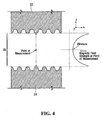
Fig. 4 shows a variation of magnetic field strength vertically across the gap in the orientation ofFig. 1 ; -
Figs. 5A-5C are, respectively, an exploded cross-sectional view, a bottom view and an exploded perspective view of the microfluidic chip, in accordance with a non-limiting embodiment of the present invention; -
Fig. 6 is a cross-sectional view of the microfluidic chip upon insertion into the gap, illustrating the presence of channels on either of two faces of the microfluidic chip; -
Fig. 7A is a perspective view of the microfluidic chip upon insertion into the gap, where the microfluidic chip in this particular figure is designed to include a channel formed of elongate traces that are aligned with lines of strong magnetic field exerted by the gap; -
Fig. 7B is a cross-sectional view through the terminal ends, the gap and the microfluidic chip ofFig. 7A , showing the presence of channels on either of two faces of the microfluidic chip; -
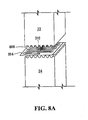
Fig. 8A is a perspective view of the microfluidic chip upon insertion into the gap, where the microfluidic chip in this particular figure is designed to include a channel formed of elongate traces that are orthogonal to lines of strong magnetic field exerted by the gap; -
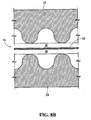
Fig. 8B is a cross-sectional view through the terminal ends, the gap and the microfluidic chip ofFig. 8A , showing the presence of channels on either of two faces of the microfluidic chip; -
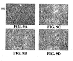
Fig. 9A shows an optical image of a test sample before separation by a microfluidic chip in accordance with an embodiment of the present invention; -
Figs. 9B-9C show optical images of the test sample ofFig. 9A after separation by the microfluidic chip at various flow rates; -
Fig. 10 is a perspective view of a microfluidic chip illustrating an alternative design with four angularly distributed channels; -
Fig. 11 is a perspective view of a magnetic separator designed to accommodate the microfluidic chip ofFig. 10 ; -
Figs. 12A-12C show various possibilities for a microfluidic chip in accordance with alternative embodiments of the present invention, wherein a container is provided for supplying a test sample to the chip; and -
Figs. 13A-13D illustrate purity of the test sample illustrated inFigs. 9A-9D , respectively, obtained by flow cytometry. - With reference to
Fig. 1 , there is shown amicrofluidic separation system 10, which includes amagnetic separator 12 and amicrofluidic chip 14. Themagnetic separator 12 includes a first magneticallyconductive member 16 and a second magneticallyconductive member 18. Also provided is amagnetic energy source 20 that is connected to the first andsecond members magnetic energy source 20 may be a permanent magnet or an arrangement (e.g., a stack) of permanent magnets. Non-limiting examples of suitable permanent magnets are those made from a rare earth material, such as Nd-Fe-B. In other non-limiting embodiments, themagnetic energy source 20 may be an electromagnet subjected to direct current (DC) or alternating current (AC). The strength of themagnetic energy source 20 is not particularly limited. For example, a suitable minimum value for the maximum magnetic energy is 40 MGOe (mega giga oersteds), although other values for the magnetic energy are within the scope of the present invention. - In a specific non-limiting embodiment, the first and
second members first member 16 and thesecond member 18 are coupled to themagnetic energy source 20. Where themagnetic energy source 20 exhibits a pair of poles, each of themembers members magnetic energy source 20. Themembers gap 26. By virtue of the magnetic conductivity of themembers magnetic energy source 20, a magnetic field will be applied across thegap 26 due to themagnetic energy source 20. - In some embodiments, such as the one shown in
Fig. 1 , either or each of the first andsecond members second members second members magnetic energy source 20. In other embodiments, the first andsecond members second members magnetic energy source 20. - Furthermore, an
alignment spacer 5 may be provided to properly separate the first andsecond members gap 26 from closing - under the force arising from the magnetic field applied across thegap 26. - To achieve a stronger magnetic field gradient within the
gap 26, and therefore improved particle separation of a test sample (e.g., in liquid, gaseous or gel form) circulating within themicrofluidic chip 14 when the latter is placed within thegap 26, the terminal end of at least one of themembers relief elements 31. Specifically,Figs. 2A-2F show example surface profiles for the terminal end of at least one of themembers relief elements 31 are of course possible without departing from the scope of the present invention. It should be appreciated that the terminal ends 22, 24 of bothmembers relief elements 31 that are mirror images of one another (vis-à-vis a horizontal plane passing through the gap 26). - It will be noted that the cross-sectional area of the terminal ends 22, 24, which is already smaller than the surface area of the
members magnetic energy source 20, is even smaller at the tips of therelief elements 31. As a result, the applied magnetic field is focused, i.e., the field across thegap 26 is stronger in the area of the peaks and weaker in the area of the valleys.Fig. 3 shows a cross-sectional view (along the x-z plane) of a simulation of magnetic field strength across thegap 26, from which it can be observed that the magnetic field is markedly stronger where thegap 26 is narrower (i.e., between opposing peaks on the surface of the terminal ends 22, 24) than where thegap 26 is wider (i.e., between opposing valleys on the surface of the terminal ends 22, 24). In particular,lines 310 of strong magnetic field are created between opposite peaks of therelief elements 31 on the surfaces of the terminal ends 22, 24. - Thus, the strength of the applied magnetic field varies laterally (in the x- and y-directions, see
Fig. 1 ) due to the existence of a pattern ofrelief elements 31 on one or both of the terminal ends 22, 24, which leads to sharper variations of the magnetic field within the gap 26 (i.e., a stronger magnetic field gradient) than in the case of flat terminal ends 22, 24. In addition, the strength of the applied magnetic field also varies according to where in thegap 26 themicrofluidic chip 14 is placed in the z-direction, i.e., as a function of distance from the terminal ends 22, 24. Specifically, with reference toFig. 4 , the magnetic field along the z-direction for a particular point in thegap 26 is seen to decrease from maximum values near the top and bottom of thegap 26, to a minimum value at the center of thegap 26. Therefore, the applied magnetic field will be weakest towards the middle of the gap 26 (in the z-direction) and strongest towards either of the terminal ends 22, 24. - Referring again to
Fig. 1 , and with additional reference toFigs. 5A-5C , themicrofluidic chip 14 is now described. Thechip 14 includes abody 30 defining a plurality of channels on respective faces of thebody 30. Thebody 30 may be made of a material having high magnetic conductivity (e.g., low carbine steel, silicon steel), although this is not a requirement of the present invention, since other materials (e.g., polymeric material such as polycarbonate or polymethyl methacrylate plastic, as well as glass or silicon) can also be used with success. In a specific non-limiting embodiment, thebody 30 may have two opposite planar faces 32, 34, withrespective channels channel 36 is onface 32 andchannel 38 is onface 34. Thechannels channels body 30 from either face or they may be built up (e.g., grown or deposited) onto the surface of thebody 30. Still other techniques are within the scope of the present invention. - An
exterior lining channels channels chip 14. Theexterior lining exterior lining exterior lining body 30 or it may be composed of separate components, each of which seals a respective one of thechannels exterior lining exterior lining - Each of the
channels inlet ports outlet ports channels body 30 may, but need not be, mirror images of one another. - A test sample can be supplied to a particular one of the
channels channel 36 viainlet port 41 and draw the test sample fromoutlet port 46. In addition, a test sample can be pumped intochannel 38 viainlet port 42 and drawn fromoutlet port 48. - In another example, the test samples can be loaded into the
channels 36, 39 by gravity. Specifically, with reference toFigs. 12A-12C , there is provided a respective contained 1202A, 1202B, 1202C that supplied, by gravity, a test sample to a channel formed in the body of a respectivemicrofluidic chip respective outlet port magnetic separator 12 ofFig. 1 if it were rotated a quatter-tum to orient thegap 26 horizontally rather than vertically. - In an embodiment, two test samples from the same source are circulated through the two
channels outlet port 46 is connected to inlet port 42 (e.g., using a via through the body 30) such that the same test sample will circulate throughchannel 36 and then throughchannel 38. - In some cases, the
channels - In other cases, the
channels respective inlet port respective outlet port 46, 48 (such as in the embodiment ofFig. 12A ). Here, a given test sample in a given one of thechannels respective inlet port respective outlet port 44,46. Thechannels - In operation, the
chip 14 is inserted into thegap 26. Of course, thegap 26 has to be sufficiently wide to accommodate thechip 14. in some embodiments, thegap 26 and thechip 14 are dimensioned so that when thechip 14 is placed into thegap 26, the exterior lining 40 of thechip 14 contacts the terminal ends 22, 24 of themembers chip 14 to be retained within thegap 26 by therelief elements 31 at the terminal ends 22, 24 of themembers gap 26 can be wider than thechip 14, and a holder external to themagnetic separator 12 can be provides. Thechip 14 is slid into thegap 26 until it reaches and engages the holder; when thechip 14 is released it will be held within thegap 26 by the holder. - With reference now to
Fig. 6 , it will be observed that once thechip 14 is inserted into thegap 26,channel 36 will be offset from the center of the gap 26 (in the z-direction) such that it is closer toterminal end 22, whilechannel 38 will also be offset from the center ofgap 26, but will be closer toterminal end 24. Thus, the test sample inchannel 36 will be confined to circulating closer toterminal end 22, while the test sample inchannel 38 will be confined to circulating closer toterminal end 24. It is noted that since there is little or no test sample volume circulating at the center of the gap 26 (in the z-direction), this means that little or no test sample volume will circulate in a plane of the z-direction where the applied magnetic field is weakest. Instead, most of the test sample is forced to circulate in planes of the z-direction where the applied where magnetic field is above its minimum value. Those skilled in the art will appreciate that where one wishes to achieve a requirement where at least X percentage of the test sample volume is to be exposed to a magnetic field of no less than Y times its minimum value, for particular values of X and Y, then techniques such as analytical modeling, simulation and/or experiment can be employed to determine suitable dimensions and configurations of thechip 14,relief elements 31 and applied magnetic field. - It should be appreciated that in the special case where a given one (or both) of the
channels lines 310 of strong magnetic field. - For example, with reference to
Fig. 7A , there is shown insertion into themagnetic separator 12 of thechip 714 that is generally planar and is generally in the center of the gap 26 (in the z-axis). Thechip 714 has been designed withelongate traces 706 in a plane of flow. Certain ones of thesetraces 706 are aligned with thelines 310 of strong magnetic field as projected onto the plane of flow. -
Fig. 7B illustrates a cross-section through the terminal ends 22, 24, thegap 26 and thebody 30, showing the twochannels body 30. It is noted that the test sample volumes in bothchannels body 30. - A similar effect may be achieved using the
microfluidic chips Figs. 12A and 12B , winch has been designed with respectiveelongate traces lines 310 of strong magnetic field as projected onto the respective plane of flow. - In an alternate embodiment, with reference, to
Fig. 8A , there is shown insertion into themagnetic separator 12 of achip 814 that is also generally planar. Thechip 814 has been designed withelongate traces 806 in a plane of flow. Certain ones of thetraces 806 cross multiple ones of tholines 310 of strong magnetic field as projected onto the plane of flow. -
Fig. 8B illustrates a cross-section through the terminal ends 22, 24, thegap 26 and thebody 30, showing the twochannels body 30. It is noted that despite the different orientation of the traces inFig. 8A when compared to those ofFig. 7A orFig. 12A , The test sample volumes in bothchannels body 30. - A similar effect may be achieved using the
chip 1214C ofFig. 12C , which has been designed withelongate traces 1236C in a plane of flow, certain ones of which cross multiple ones of thelines 310 of strong magnetic field as projected onto the plane of flow. - Non-limiting examples of application of the
microfluidic separation system 12 include the separation and/or enrichment of target material from biological test samples such as blood samples, bacterial and/or cell suspensions or extracts, protein or antibody solutions and various buffers. - In a specific example of application, the cultured Human Hepatocellular Carcinoma cell (HepG2) was used as the target cell for a cell separation experiment. The cell was labeled with magnetic nanoparticles with a diameter of 10nm. These nanoparticles fluoresce in nature. The labeled HepG2 was mixed with non-labeled fresh human red blood cells. The ratio of HepG2 to red blood cells was 10%. The cell mixture was suspended in a separation buffer containing 2% fetal bovine serum and 1mM EDTA in phosphate buffered saline (PBS). The final total cell concentration is adjusted to 1×10⁷ cell/ml. The separation results are analysed by using flow cytometry.
- For the separation efficiency study, flow rates of 100-500µl/min controlled by syringe pump were used. A chip in accordance with an embodiment of the present invention was inserted to the gap (previously labeled 26). The cell mixture was supplied to the chip. The target cells (labeled with magnetic nanoparticles) were trapped inside the channels (previously labeled as 36, 38) due to the high-intensity / high-gradient magnetic field, while non-labeled "debris cells" flowed out the separation chip. After the cell mixture fully passed through the separation chip, 5ml of 1 × PBS was used to flush the separation channel at a flow rate of 500µl/min. This process washes out the un-trapped cells in the channel of the chip. Finally, the chip was taken out from the separation gap. The trapped cells were flushed out by using 1 × PBS at a flow rate of 1ml/min.
-
Fig. 9A shows the optical image of cells before separation under fluorescence microscope under 365 nm UV light excitation. The target cells (i.e., those labeled with magnetic nanoparticles) are easy to identify under the microscope because of their fluorescence, and some are labeled as 900 inFig. 9A for convenience. It is noted that the target cells are present among a greater number of non-target cells. In contrast,Figs. 9B-9D show the optical image of cells after separation under the same optical conditions, demonstrating a certain degree of purity of the target cells. The difference betweenFigs. 9B, 9C and 9D is the flow rate through the chip, which was 200µl/min, 300µl/min and 400µl/min, respectively. - The purity of the separated target cells was analyzed by flow cytometry and is illustrated in
Figs. 13A-13D . Specifically, the result for the original cell mixture (refer toFig. 9A ) is shown inFig. 13A , recalling that the percentage of HepG2 cells was 10% before separation.Figs. 13B, 13C and 13D show the separation results for the above mentioned flow rates of 200µl/min, 300µl/min and 400µl/min, respectively (refer toFigs. 9B, 9C and 9D ). - Those skilled in the art will appreciate that although the
chip 14 has been described whosebody 30 is generally planar, it is nevertheless possible to design other chip shapes without departing from the scope of the present invention. In particular,Fig. 10 shows amicrofluidic chip 1014 designed as a cylinder with abody 1030 defining four (4) angularly distributedchannels body 1030, although the faces need not be curved (and therefore thebody 1030 need not be cylindrical) in all embodiments. Anexterior lining 1040 forms a sheath of the cylinder. The fourchannels chip 1014. Such an arrangement may be particularly useful where, as shown inFig. 11 , the magnetic separator 1112 is designed to have a four-pole design, namely, with two pairs of opposite-ended poles (1102 / 1106 and 1104 / 1108) arranged in such a way as to leave a passageway for insertion of thechip 1014. In this way, up to four individual test sample volumes can be subjected to magnetic separation simultaneously. - Those skilled in the art will appreciate that strong magnetic forces may be obtainable because of the comparatively higher field density and gradient of field density provided by certain embodiments of the microfluidic separation system of the present invention. This allows improved separation and/or extraction to be achieved with finer magnetic particles such as magnetic nanoparticles and magnetic quantum dots. Moreover, the
microfluidic chip 14 has a simple structure, offering lower costs and higher efficiency when compared to conventional technologies. Also, theplanar channels body 30 provide themicrofluidic chip 14 with a small dead volume, thus enabling the processing of smaller test sample volumes and making the system suitable for the purification of rare or costly samples, such as stem cells for example. - While specific embodiments of the present invention have been described and illustrated, it will be apparent to those skilled in the art that numerous modifications and variations can be made without departing from the scope of the invention as defined in the appended claims.
Claims (15)
- A system (10) comprising:a magnetic separator (12) comprising a first pole end (22, 24, 1102, 1104, 1106, 1108) and an opposing second pole end (22, 24, 1102, 1104, 1106, 1108) separated by a gap (26), for applying a magnetic field across said gap, said magnetic field decreasing from said pole ends towards an area of minimum field between said pole ends; anda microfluidic chip (14, 714, 814, 1014, 1214A, 1214B, 1214C) having a first face (32, 34) and an opposite second face (32, 34), defining a first fluid channel (36, 38, 706, 806, 1036A, 1036B, 1036C, 1036D, 1236A, 1236B, 1236C) adjacent said first face and a second fluid channel (36, 38, 706, 806, 1036A, 1036B, 1036C, 1036D, 1236A, 1236B, 1236C) adjacent said second face, said chip inserted into said gap with said area of minimum field being positioned between, and offset from, said first and second channels.
- The system of claim 1, wherein at least one of said pole ends has a surface pattern of peaks and valleys.
- The system of claim 1 or claim 2, wherein at least one of said pole ends has a corrugated surface.
- The system of claim 3, wherein said corrugated surface has tips (31) and at least one of said first and second channels comprises traces patterned to align with said tips.
- The system of claim 4, wherein said tips and said traces are elongate and generally parallel to one another.
- The system of claim 5, wherein selected ones of said traces are connected by bends, to establish a meandrous flow path.
- The system of any one of claims 1 to 6, wherein
said magnetic separator comprises:a magnetic energy source (20);first and second magnetically conductive members (16, 18, 1102, 1104, 1106, 1108) leading from the magnetic energy source and having respective terminal ends forming said first and second pole ends (22, 24, 1102, 1104, 1106, 1108); andthe terminal ends of the first and second members being separated by said gapover which said magnetic field is applied due to the magnetic energy source; and said microfluidic chip comprises:wherein upon insertion of the microfluidic chip into the gap, the area of minimum field is positioned between, and offset from, a first channel on a first face of the body and a second channel on a second face of the body, and a first one of the test sample volumes in the first channel is confined to circulating closer to the terminal end of the first member and a second one of the test sample volumes in the second channel is confined to circulating closer to the terminal end of the second member.a body (30, 1030) defining a plurality of channels (36, 38, 706, 806, 1036A, 1036B, 1036C, 1036D, 1236A, 1236B, 1236C) on respective faces of the body;andan exterior lining (40A, 40B, 1040) that seals the plurality of channels to allow separate test sample volumes to circulate in at least two of the channels; - The system defined in claim 7, wherein at least two of the channels are mirror images of one another on respective faces of the body.
- The system defined in claim 7 or claim 8, wherein each of the first and second members comprises a respective first yoke connected to a respective second yoke, the respective first yoke having a cross-sectional area and being connected to the source of magnetic energy, the respective second yoke exhibiting the respective terminal end of the respective member, the respective terminal end of the respective member having a cross-sectional area less than the cross-sectional area of the respective first yoke.
- The system defined in any one of claims 1 to 9, wherein the microfluidic chip includes a respective inlet port (41, 42) and a respective outlet port (46, 48, 1246A, 1246B, 1246C) for each of the channels.
- The system defined in any one of claims 1 to 10, wherein the microfluidic chip comprises a container (1202A, 1202B, 1202C) for supplying at least one of the test sample volumes into the respective at least one of the channels by gravity.
- The system defined in any one of claims 1 to 11, wherein said pole ends exhibit respective patterns of relief elements (31).
- The system defined in claim 12, wherein the patterns of relief elements are mirror images of one another.
- The system defined in any one of claims 1 to 13, wherein at least two of the channels include respective sets of generally parallel elongate traces.
- The system defined in any one of claims 1 to 14, further comprising a holder external to the magnetic separator and configured to retain the micro fluidic chip within the gap.
Applications Claiming Priority (2)
| Application Number | Priority Date | Filing Date | Title |
|---|---|---|---|
| US93544307P | 2007-08-13 | 2007-08-13 | |
| PCT/SG2008/000300 WO2009022994A1 (en) | 2007-08-13 | 2008-08-13 | Microfluidic separation system |
Publications (3)
| Publication Number | Publication Date |
|---|---|
| EP2185289A1 EP2185289A1 (en) | 2010-05-19 |
| EP2185289A4 EP2185289A4 (en) | 2013-11-27 |
| EP2185289B1 true EP2185289B1 (en) | 2015-02-25 |
Family
ID=40350927
Family Applications (1)
| Application Number | Title | Priority Date | Filing Date |
|---|---|---|---|
| EP08794205.8A Not-in-force EP2185289B1 (en) | 2007-08-13 | 2008-08-13 | Microfluidic separation system |
Country Status (3)
| Country | Link |
|---|---|
| US (1) | US8268177B2 (en) |
| EP (1) | EP2185289B1 (en) |
| WO (1) | WO2009022994A1 (en) |
Families Citing this family (17)
| Publication number | Priority date | Publication date | Assignee | Title |
|---|---|---|---|---|
| CN102470373B (en) * | 2009-07-17 | 2014-11-26 | 皇家飞利浦电子股份有限公司 | Apparatus for the enrichment of magnetic particles |
| EP2701850B1 (en) * | 2011-04-27 | 2018-08-15 | Becton Dickinson and Company | Devices and methods for separating magnetically labeled moieties in a sample |
| US11931740B2 (en) | 2012-02-13 | 2024-03-19 | Neumodx Molecular, Inc. | System and method for processing and detecting nucleic acids |
| US9637775B2 (en) | 2012-02-13 | 2017-05-02 | Neumodx Molecular, Inc. | System and method for processing biological samples |
| US9604213B2 (en) | 2012-02-13 | 2017-03-28 | Neumodx Molecular, Inc. | System and method for processing and detecting nucleic acids |
| EP2814942A4 (en) | 2012-02-13 | 2015-09-23 | Neumodx Molecular Inc | Microfluidic cartridge for processing and detecting nucleic acids |
| US11485968B2 (en) | 2012-02-13 | 2022-11-01 | Neumodx Molecular, Inc. | Microfluidic cartridge for processing and detecting nucleic acids |
| CN102854304B (en) * | 2012-07-06 | 2015-09-16 | 武汉大学 | A kind of pathogen detection method based on micro-fluidic chip |
| WO2014062719A2 (en) | 2012-10-15 | 2014-04-24 | Nanocellect Biomedical, Inc. | Systems, apparatus, and methods for sorting particles |
| US20140120544A1 (en) | 2012-10-25 | 2014-05-01 | Neumodx Molecular, Inc. | Method and materials for isolation of nucleic acid materials |
| WO2015058206A1 (en) * | 2013-10-18 | 2015-04-23 | The General Hosptial Corporation | Microfluidic sorting using high gradient magnetic fields |
| EP3314123B1 (en) * | 2015-06-23 | 2024-04-03 | NanoCellect Biomedical, Inc. | Systems, apparatuses, and methods for cell sorting and flow cytometry |
| KR101583017B1 (en) * | 2015-07-17 | 2016-01-06 | 주식회사 지노바이오 | MIP(Magnetic Iron Particles) Discrimination System |
| US10625272B2 (en) * | 2015-11-18 | 2020-04-21 | Industrial Technology Research Institute | Magnetic separator |
| US20190126288A1 (en) * | 2016-05-12 | 2019-05-02 | University Of Florida Research Foundation, Inc. | Magnetic separation system and devices |
| KR101888636B1 (en) * | 2017-06-02 | 2018-08-14 | 지트로닉스 주식회사 | Magnetophoresis biochip |
| EP3710167A4 (en) * | 2017-11-14 | 2021-08-18 | University of Florida Research Foundation | Magnetic separation system and devices |
Family Cites Families (19)
| Publication number | Priority date | Publication date | Assignee | Title |
|---|---|---|---|---|
| US3567026A (en) | 1968-09-20 | 1971-03-02 | Massachusetts Inst Technology | Magnetic device |
| US3676337A (en) | 1970-07-09 | 1972-07-11 | Massachusetts Inst Technology | Process for magnetic separation |
| US3902994A (en) | 1973-05-16 | 1975-09-02 | Emanuel Maxwell | High gradient type magnetic separator with continuously moving matrix |
| US4663029A (en) | 1985-04-08 | 1987-05-05 | Massachusetts Institute Of Technology | Method and apparatus for continuous magnetic separation |
| US5200084A (en) | 1990-09-26 | 1993-04-06 | Immunicon Corporation | Apparatus and methods for magnetic separation |
| US5186827A (en) | 1991-03-25 | 1993-02-16 | Immunicon Corporation | Apparatus for magnetic separation featuring external magnetic means |
| US5466574A (en) | 1991-03-25 | 1995-11-14 | Immunivest Corporation | Apparatus and methods for magnetic separation featuring external magnetic means |
| US6036857A (en) | 1998-02-20 | 2000-03-14 | Florida State University Research Foundation, Inc. | Apparatus for continuous magnetic separation of components from a mixture |
| ES2279600T3 (en) | 1998-03-12 | 2007-08-16 | Miltenyi Biotec Gmbh | MICROCOLUMN SYSTEM FOR MAGNETIC SEPARATION. |
| US6361749B1 (en) | 1998-08-18 | 2002-03-26 | Immunivest Corporation | Apparatus and methods for magnetic separation |
| US6939032B2 (en) * | 2001-10-25 | 2005-09-06 | Erie Scientific Company | Cover slip mixing apparatus |
| EP1331035A1 (en) | 2002-01-23 | 2003-07-30 | F. Hoffmann-La Roche AG | Apparatus for retaining magnetic particles within a flow-through cell |
| WO2003072227A1 (en) * | 2002-02-15 | 2003-09-04 | President And Fellows Of Harvard College | Fluidics systems including magnetic or electric fields and methods of using the same |
| US20050148064A1 (en) * | 2003-12-29 | 2005-07-07 | Intel Corporation | Microfluid molecular-flow fractionator and bioreactor with integrated active/passive diffusion barrier |
| US8173078B2 (en) | 2004-04-28 | 2012-05-08 | Industrial Technology Research Institute | Gravity-driven micropump |
| US20050274650A1 (en) | 2004-06-09 | 2005-12-15 | Georgia Tech Research Corporation | Blood separation systems in micro device format and fabrication methods |
| WO2006054991A1 (en) | 2004-11-17 | 2006-05-26 | Immunivest Corporation | Magnetic enrichment of circulating cells, fragments and debris for enabling hts proteomics and genomics in disease detection |
| US20060223178A1 (en) | 2005-04-05 | 2006-10-05 | Tom Barber | Devices and methods for magnetic enrichment of cells and other particles |
| US9220831B2 (en) | 2005-10-06 | 2015-12-29 | Children's Medical Center Corporation | Device and method for combined microfluidic-micromagnetic separation of material in continuous flow |
-
2008
- 2008-08-13 EP EP08794205.8A patent/EP2185289B1/en not_active Not-in-force
- 2008-08-13 WO PCT/SG2008/000300 patent/WO2009022994A1/en active Application Filing
- 2008-08-13 US US12/673,160 patent/US8268177B2/en not_active Expired - Fee Related
Also Published As
| Publication number | Publication date |
|---|---|
| US20120024770A1 (en) | 2012-02-02 |
| EP2185289A4 (en) | 2013-11-27 |
| WO2009022994A1 (en) | 2009-02-19 |
| EP2185289A1 (en) | 2010-05-19 |
| US8268177B2 (en) | 2012-09-18 |
| WO2009022994A8 (en) | 2009-04-16 |
Similar Documents
| Publication | Publication Date | Title |
|---|---|---|
| EP2185289B1 (en) | Microfluidic separation system | |
| US10444125B2 (en) | Devices and methods for separating magnetically labeled moieties in a sample | |
| Zhu et al. | Continuous-flow ferrohydrodynamic sorting of particles and cells in microfluidic devices | |
| Gijs et al. | Microfluidic applications of magnetic particles for biological analysis and catalysis | |
| EP2864051B1 (en) | Sorting particles using high gradient magnetic fields | |
| Xia et al. | Combined microfluidic-micromagnetic separation of living cells in continuous flow | |
| US8292083B2 (en) | Method and apparatus for separating particles, cells, molecules and particulates | |
| US9220831B2 (en) | Device and method for combined microfluidic-micromagnetic separation of material in continuous flow | |
| Qu et al. | A glass microfluidic chip for continuous blood cell sorting by a magnetic gradient without labeling | |
| JP4331591B2 (en) | Method, element and apparatus for wet separation of magnetic fine particles | |
| EP0975744A1 (en) | Fractional cell sorter | |
| Afshar et al. | Magnetic particle dosing and size separation in a microfluidic channel | |
| Alves et al. | Trends in analytical separations of magnetic (nano) particles | |
| WO2008007270A2 (en) | A method for manipulating magnetic particles in a liquid medium | |
| Zhou et al. | Multiphase ferrofluid flows for micro-particle focusing and separation | |
| CN114100704B (en) | Magnetic separation micro-fluidic chip and manufacturing method thereof | |
| CN110621313B (en) | Methods and systems for pulling DNA, RNA, and other biomolecules through nanopores using soft magnetic structures | |
| Mekkaoui et al. | Nanonewton magnetophoretic microtrap array for microsystems | |
| US20210170423A1 (en) | Magnetic separation system and devices | |
| Saeed et al. | Hydrodynamic Assists Magnetophoreses Rare Cancer cells Separation in Microchannel Simulation and Experimental Verifications | |
| Hosseini | DESIGN, FABRICATION, AND CHARACTERIZATION OF MICRO-ELECTROMAGNETIC DEVICES FOR MANIPULATION OF MAGNETIC PARTICLES | |
| Sinha | Characterizing magnetic particle transport for microfluidic applications | |
| Zeng | Magnetic manipulation of particles and cells in ferrofluid flow through straight microchannels using two magnets |
Legal Events
| Date | Code | Title | Description |
|---|---|---|---|
| PUAI | Public reference made under article 153(3) epc to a published international application that has entered the european phase |
Free format text: ORIGINAL CODE: 0009012 |
|
| 17P | Request for examination filed |
Effective date: 20100304 |
|
| AK | Designated contracting states |
Kind code of ref document: A1 Designated state(s): AT BE BG CH CY CZ DE DK EE ES FI FR GB GR HR HU IE IS IT LI LT LU LV MC MT NL NO PL PT RO SE SI SK TR |
|
| AX | Request for extension of the european patent |
Extension state: AL BA MK RS |
|
| DAX | Request for extension of the european patent (deleted) | ||
| A4 | Supplementary search report drawn up and despatched |
Effective date: 20131030 |
|
| RIC1 | Information provided on ipc code assigned before grant |
Ipc: G01N 33/50 20060101ALN20131024BHEP Ipc: G01N 27/00 20060101ALN20131024BHEP Ipc: B03C 1/035 20060101AFI20131024BHEP Ipc: B03C 1/00 20060101ALI20131024BHEP Ipc: B03C 1/28 20060101ALI20131024BHEP Ipc: G01N 35/00 20060101ALN20131024BHEP Ipc: B81B 1/00 20060101ALN20131024BHEP Ipc: B03C 1/32 20060101ALI20131024BHEP |
|
| GRAP | Despatch of communication of intention to grant a patent |
Free format text: ORIGINAL CODE: EPIDOSNIGR1 |
|
| RIC1 | Information provided on ipc code assigned before grant |
Ipc: G01N 33/50 20060101ALN20140702BHEP Ipc: G01N 27/00 20060101ALN20140702BHEP Ipc: B81B 1/00 20060101ALN20140702BHEP Ipc: B03C 1/01 20060101ALI20140702BHEP Ipc: G01N 35/00 20060101ALN20140702BHEP Ipc: B03C 1/035 20060101AFI20140702BHEP Ipc: B03C 1/32 20060101ALI20140702BHEP Ipc: B03C 1/00 20060101ALI20140702BHEP Ipc: B03C 1/033 20060101ALN20140702BHEP Ipc: B03C 1/28 20060101ALI20140702BHEP |
|
| INTG | Intention to grant announced |
Effective date: 20140725 |
|
| RIC1 | Information provided on ipc code assigned before grant |
Ipc: B03C 1/033 20060101ALN20140714BHEP Ipc: B81B 1/00 20060101ALN20140714BHEP Ipc: B03C 1/035 20060101AFI20140714BHEP Ipc: G01N 27/00 20060101ALN20140714BHEP Ipc: B03C 1/32 20060101ALI20140714BHEP Ipc: G01N 33/50 20060101ALN20140714BHEP Ipc: B03C 1/00 20060101ALI20140714BHEP Ipc: B03C 1/28 20060101ALI20140714BHEP Ipc: G01N 35/00 20060101ALN20140714BHEP Ipc: B03C 1/01 20060101ALI20140714BHEP |
|
| GRAP | Despatch of communication of intention to grant a patent |
Free format text: ORIGINAL CODE: EPIDOSNIGR1 |
|
| RIC1 | Information provided on ipc code assigned before grant |
Ipc: B03C 1/28 20060101ALI20141016BHEP Ipc: G01N 27/00 20060101ALN20141016BHEP Ipc: G01N 35/00 20060101ALN20141016BHEP Ipc: B03C 1/00 20060101ALI20141016BHEP Ipc: B03C 1/32 20060101ALI20141016BHEP Ipc: B03C 1/033 20060101ALN20141016BHEP Ipc: B81B 1/00 20060101ALN20141016BHEP Ipc: G01N 33/50 20060101ALN20141016BHEP Ipc: B03C 1/035 20060101AFI20141016BHEP Ipc: B03C 1/01 20060101ALI20141016BHEP |
|
| INTG | Intention to grant announced |
Effective date: 20141029 |
|
| GRAS | Grant fee paid |
Free format text: ORIGINAL CODE: EPIDOSNIGR3 |
|
| GRAA | (expected) grant |
Free format text: ORIGINAL CODE: 0009210 |
|
| AK | Designated contracting states |
Kind code of ref document: B1 Designated state(s): AT BE BG CH CY CZ DE DK EE ES FI FR GB GR HR HU IE IS IT LI LT LU LV MC MT NL NO PL PT RO SE SI SK TR |
|
| REG | Reference to a national code |
Ref country code: GB Ref legal event code: FG4D |
|
| REG | Reference to a national code |
Ref country code: CH Ref legal event code: EP |
|
| REG | Reference to a national code |
Ref country code: IE Ref legal event code: FG4D |
|
| REG | Reference to a national code |
Ref country code: DE Ref legal event code: R096 Ref document number: 602008036827 Country of ref document: DE Effective date: 20150409 |
|
| REG | Reference to a national code |
Ref country code: AT Ref legal event code: REF Ref document number: 711459 Country of ref document: AT Kind code of ref document: T Effective date: 20150415 |
|
| REG | Reference to a national code |
Ref country code: NL Ref legal event code: VDEP Effective date: 20150225 |
|
| REG | Reference to a national code |
Ref country code: AT Ref legal event code: MK05 Ref document number: 711459 Country of ref document: AT Kind code of ref document: T Effective date: 20150225 |
|
| REG | Reference to a national code |
Ref country code: LT Ref legal event code: MG4D |
|
| PG25 | Lapsed in a contracting state [announced via postgrant information from national office to epo] |
Ref country code: NO Free format text: LAPSE BECAUSE OF FAILURE TO SUBMIT A TRANSLATION OF THE DESCRIPTION OR TO PAY THE FEE WITHIN THE PRESCRIBED TIME-LIMIT Effective date: 20150525 Ref country code: SE Free format text: LAPSE BECAUSE OF FAILURE TO SUBMIT A TRANSLATION OF THE DESCRIPTION OR TO PAY THE FEE WITHIN THE PRESCRIBED TIME-LIMIT Effective date: 20150225 Ref country code: HR Free format text: LAPSE BECAUSE OF FAILURE TO SUBMIT A TRANSLATION OF THE DESCRIPTION OR TO PAY THE FEE WITHIN THE PRESCRIBED TIME-LIMIT Effective date: 20150225 Ref country code: FI Free format text: LAPSE BECAUSE OF FAILURE TO SUBMIT A TRANSLATION OF THE DESCRIPTION OR TO PAY THE FEE WITHIN THE PRESCRIBED TIME-LIMIT Effective date: 20150225 Ref country code: ES Free format text: LAPSE BECAUSE OF FAILURE TO SUBMIT A TRANSLATION OF THE DESCRIPTION OR TO PAY THE FEE WITHIN THE PRESCRIBED TIME-LIMIT Effective date: 20150225 Ref country code: LT Free format text: LAPSE BECAUSE OF FAILURE TO SUBMIT A TRANSLATION OF THE DESCRIPTION OR TO PAY THE FEE WITHIN THE PRESCRIBED TIME-LIMIT Effective date: 20150225 |
|
| REG | Reference to a national code |
Ref country code: FR Ref legal event code: PLFP Year of fee payment: 8 |
|
| PG25 | Lapsed in a contracting state [announced via postgrant information from national office to epo] |
Ref country code: IS Free format text: LAPSE BECAUSE OF FAILURE TO SUBMIT A TRANSLATION OF THE DESCRIPTION OR TO PAY THE FEE WITHIN THE PRESCRIBED TIME-LIMIT Effective date: 20150625 Ref country code: LV Free format text: LAPSE BECAUSE OF FAILURE TO SUBMIT A TRANSLATION OF THE DESCRIPTION OR TO PAY THE FEE WITHIN THE PRESCRIBED TIME-LIMIT Effective date: 20150225 Ref country code: GR Free format text: LAPSE BECAUSE OF FAILURE TO SUBMIT A TRANSLATION OF THE DESCRIPTION OR TO PAY THE FEE WITHIN THE PRESCRIBED TIME-LIMIT Effective date: 20150526 Ref country code: AT Free format text: LAPSE BECAUSE OF FAILURE TO SUBMIT A TRANSLATION OF THE DESCRIPTION OR TO PAY THE FEE WITHIN THE PRESCRIBED TIME-LIMIT Effective date: 20150225 |
|
| PG25 | Lapsed in a contracting state [announced via postgrant information from national office to epo] |
Ref country code: NL Free format text: LAPSE BECAUSE OF FAILURE TO SUBMIT A TRANSLATION OF THE DESCRIPTION OR TO PAY THE FEE WITHIN THE PRESCRIBED TIME-LIMIT Effective date: 20150225 |
|
| PG25 | Lapsed in a contracting state [announced via postgrant information from national office to epo] |
Ref country code: CZ Free format text: LAPSE BECAUSE OF FAILURE TO SUBMIT A TRANSLATION OF THE DESCRIPTION OR TO PAY THE FEE WITHIN THE PRESCRIBED TIME-LIMIT Effective date: 20150225 Ref country code: SK Free format text: LAPSE BECAUSE OF FAILURE TO SUBMIT A TRANSLATION OF THE DESCRIPTION OR TO PAY THE FEE WITHIN THE PRESCRIBED TIME-LIMIT Effective date: 20150225 Ref country code: DK Free format text: LAPSE BECAUSE OF FAILURE TO SUBMIT A TRANSLATION OF THE DESCRIPTION OR TO PAY THE FEE WITHIN THE PRESCRIBED TIME-LIMIT Effective date: 20150225 Ref country code: RO Free format text: LAPSE BECAUSE OF FAILURE TO SUBMIT A TRANSLATION OF THE DESCRIPTION OR TO PAY THE FEE WITHIN THE PRESCRIBED TIME-LIMIT Effective date: 20150225 Ref country code: EE Free format text: LAPSE BECAUSE OF FAILURE TO SUBMIT A TRANSLATION OF THE DESCRIPTION OR TO PAY THE FEE WITHIN THE PRESCRIBED TIME-LIMIT Effective date: 20150225 |
|
| PGFP | Annual fee paid to national office [announced via postgrant information from national office to epo] |
Ref country code: GB Payment date: 20150818 Year of fee payment: 8 |
|
| REG | Reference to a national code |
Ref country code: DE Ref legal event code: R097 Ref document number: 602008036827 Country of ref document: DE |
|
| PG25 | Lapsed in a contracting state [announced via postgrant information from national office to epo] |
Ref country code: PL Free format text: LAPSE BECAUSE OF FAILURE TO SUBMIT A TRANSLATION OF THE DESCRIPTION OR TO PAY THE FEE WITHIN THE PRESCRIBED TIME-LIMIT Effective date: 20150225 |
|
| PGFP | Annual fee paid to national office [announced via postgrant information from national office to epo] |
Ref country code: FR Payment date: 20150828 Year of fee payment: 8 |
|
| PG25 | Lapsed in a contracting state [announced via postgrant information from national office to epo] |
Ref country code: IT Free format text: LAPSE BECAUSE OF FAILURE TO SUBMIT A TRANSLATION OF THE DESCRIPTION OR TO PAY THE FEE WITHIN THE PRESCRIBED TIME-LIMIT Effective date: 20150225 |
|
| PLBE | No opposition filed within time limit |
Free format text: ORIGINAL CODE: 0009261 |
|
| STAA | Information on the status of an ep patent application or granted ep patent |
Free format text: STATUS: NO OPPOSITION FILED WITHIN TIME LIMIT |
|
| 26N | No opposition filed |
Effective date: 20151126 |
|
| PG25 | Lapsed in a contracting state [announced via postgrant information from national office to epo] |
Ref country code: SI Free format text: LAPSE BECAUSE OF FAILURE TO SUBMIT A TRANSLATION OF THE DESCRIPTION OR TO PAY THE FEE WITHIN THE PRESCRIBED TIME-LIMIT Effective date: 20150225 |
|
| PG25 | Lapsed in a contracting state [announced via postgrant information from national office to epo] |
Ref country code: LU Free format text: LAPSE BECAUSE OF FAILURE TO SUBMIT A TRANSLATION OF THE DESCRIPTION OR TO PAY THE FEE WITHIN THE PRESCRIBED TIME-LIMIT Effective date: 20150813 Ref country code: MC Free format text: LAPSE BECAUSE OF FAILURE TO SUBMIT A TRANSLATION OF THE DESCRIPTION OR TO PAY THE FEE WITHIN THE PRESCRIBED TIME-LIMIT Effective date: 20150225 |
|
| REG | Reference to a national code |
Ref country code: CH Ref legal event code: PL |
|
| PG25 | Lapsed in a contracting state [announced via postgrant information from national office to epo] |
Ref country code: CH Free format text: LAPSE BECAUSE OF NON-PAYMENT OF DUE FEES Effective date: 20150831 Ref country code: LI Free format text: LAPSE BECAUSE OF NON-PAYMENT OF DUE FEES Effective date: 20150831 |
|
| PG25 | Lapsed in a contracting state [announced via postgrant information from national office to epo] |
Ref country code: BE Free format text: LAPSE BECAUSE OF FAILURE TO SUBMIT A TRANSLATION OF THE DESCRIPTION OR TO PAY THE FEE WITHIN THE PRESCRIBED TIME-LIMIT Effective date: 20150225 |
|
| REG | Reference to a national code |
Ref country code: IE Ref legal event code: MM4A |
|
| PG25 | Lapsed in a contracting state [announced via postgrant information from national office to epo] |
Ref country code: IE Free format text: LAPSE BECAUSE OF NON-PAYMENT OF DUE FEES Effective date: 20150813 |
|
| PGFP | Annual fee paid to national office [announced via postgrant information from national office to epo] |
Ref country code: DE Payment date: 20160824 Year of fee payment: 9 |
|
| PG25 | Lapsed in a contracting state [announced via postgrant information from national office to epo] |
Ref country code: MT Free format text: LAPSE BECAUSE OF FAILURE TO SUBMIT A TRANSLATION OF THE DESCRIPTION OR TO PAY THE FEE WITHIN THE PRESCRIBED TIME-LIMIT Effective date: 20150225 |
|
| GBPC | Gb: european patent ceased through non-payment of renewal fee |
Effective date: 20160813 |
|
| REG | Reference to a national code |
Ref country code: FR Ref legal event code: ST Effective date: 20170428 |
|
| PG25 | Lapsed in a contracting state [announced via postgrant information from national office to epo] |
Ref country code: HU Free format text: LAPSE BECAUSE OF FAILURE TO SUBMIT A TRANSLATION OF THE DESCRIPTION OR TO PAY THE FEE WITHIN THE PRESCRIBED TIME-LIMIT; INVALID AB INITIO Effective date: 20080813 Ref country code: BG Free format text: LAPSE BECAUSE OF FAILURE TO SUBMIT A TRANSLATION OF THE DESCRIPTION OR TO PAY THE FEE WITHIN THE PRESCRIBED TIME-LIMIT Effective date: 20150225 |
|
| PG25 | Lapsed in a contracting state [announced via postgrant information from national office to epo] |
Ref country code: CY Free format text: LAPSE BECAUSE OF FAILURE TO SUBMIT A TRANSLATION OF THE DESCRIPTION OR TO PAY THE FEE WITHIN THE PRESCRIBED TIME-LIMIT Effective date: 20150225 |
|
| PG25 | Lapsed in a contracting state [announced via postgrant information from national office to epo] |
Ref country code: GB Free format text: LAPSE BECAUSE OF NON-PAYMENT OF DUE FEES Effective date: 20160813 Ref country code: FR Free format text: LAPSE BECAUSE OF NON-PAYMENT OF DUE FEES Effective date: 20160831 |
|
| PG25 | Lapsed in a contracting state [announced via postgrant information from national office to epo] |
Ref country code: TR Free format text: LAPSE BECAUSE OF FAILURE TO SUBMIT A TRANSLATION OF THE DESCRIPTION OR TO PAY THE FEE WITHIN THE PRESCRIBED TIME-LIMIT Effective date: 20150225 |
|
| REG | Reference to a national code |
Ref country code: DE Ref legal event code: R082 Ref document number: 602008036827 Country of ref document: DE |
|
| REG | Reference to a national code |
Ref country code: DE Ref legal event code: R119 Ref document number: 602008036827 Country of ref document: DE |
|
| PG25 | Lapsed in a contracting state [announced via postgrant information from national office to epo] |
Ref country code: PT Free format text: LAPSE BECAUSE OF FAILURE TO SUBMIT A TRANSLATION OF THE DESCRIPTION OR TO PAY THE FEE WITHIN THE PRESCRIBED TIME-LIMIT Effective date: 20150225 |
|
| PG25 | Lapsed in a contracting state [announced via postgrant information from national office to epo] |
Ref country code: DE Free format text: LAPSE BECAUSE OF NON-PAYMENT OF DUE FEES Effective date: 20180301 |