EP2814677B1 - Dispositif pour éviter le mouvement de roulis et de tangage d'un véhicule industriel - Google Patents
Dispositif pour éviter le mouvement de roulis et de tangage d'un véhicule industriel Download PDFInfo
- Publication number
- EP2814677B1 EP2814677B1 EP13709057.7A EP13709057A EP2814677B1 EP 2814677 B1 EP2814677 B1 EP 2814677B1 EP 13709057 A EP13709057 A EP 13709057A EP 2814677 B1 EP2814677 B1 EP 2814677B1
- Authority
- EP
- European Patent Office
- Prior art keywords
- vehicle
- wheel
- supporting
- floor
- roll
- Prior art date
- Legal status (The legal status is an assumption and is not a legal conclusion. Google has not performed a legal analysis and makes no representation as to the accuracy of the status listed.)
- Active
Links
- 230000000694 effects Effects 0.000 claims description 39
- 230000001133 acceleration Effects 0.000 claims description 22
- 230000007246 mechanism Effects 0.000 claims description 18
- 238000005259 measurement Methods 0.000 claims description 16
- 238000001514 detection method Methods 0.000 claims description 8
- 230000008713 feedback mechanism Effects 0.000 claims description 8
- 238000012545 processing Methods 0.000 claims description 8
- 230000009897 systematic effect Effects 0.000 claims description 3
- 230000033001 locomotion Effects 0.000 description 69
- 238000000034 method Methods 0.000 description 34
- 230000006870 function Effects 0.000 description 23
- 239000000725 suspension Substances 0.000 description 12
- 238000012546 transfer Methods 0.000 description 8
- 238000012937 correction Methods 0.000 description 7
- 238000013459 approach Methods 0.000 description 6
- 230000035939 shock Effects 0.000 description 6
- 238000010586 diagram Methods 0.000 description 5
- 239000006096 absorbing agent Substances 0.000 description 4
- 238000010276 construction Methods 0.000 description 4
- 230000008901 benefit Effects 0.000 description 3
- 238000011217 control strategy Methods 0.000 description 3
- 230000004044 response Effects 0.000 description 3
- 238000010521 absorption reaction Methods 0.000 description 2
- 230000008859 change Effects 0.000 description 2
- 238000006243 chemical reaction Methods 0.000 description 2
- 238000012986 modification Methods 0.000 description 2
- 230000004048 modification Effects 0.000 description 2
- 238000012544 monitoring process Methods 0.000 description 2
- 230000007935 neutral effect Effects 0.000 description 2
- 230000003287 optical effect Effects 0.000 description 2
- 230000002085 persistent effect Effects 0.000 description 2
- 101150103244 ACT1 gene Proteins 0.000 description 1
- 241000167854 Bourreria succulenta Species 0.000 description 1
- 101150023061 acpP gene Proteins 0.000 description 1
- 239000000956 alloy Substances 0.000 description 1
- 229910045601 alloy Inorganic materials 0.000 description 1
- 230000003466 anti-cipated effect Effects 0.000 description 1
- 230000009286 beneficial effect Effects 0.000 description 1
- 230000005540 biological transmission Effects 0.000 description 1
- 238000004364 calculation method Methods 0.000 description 1
- 239000000969 carrier Substances 0.000 description 1
- 235000019693 cherries Nutrition 0.000 description 1
- 230000001186 cumulative effect Effects 0.000 description 1
- 230000001934 delay Effects 0.000 description 1
- 238000013461 design Methods 0.000 description 1
- 239000013013 elastic material Substances 0.000 description 1
- 238000001914 filtration Methods 0.000 description 1
- 230000004927 fusion Effects 0.000 description 1
- 230000010354 integration Effects 0.000 description 1
- 238000012886 linear function Methods 0.000 description 1
- 230000009467 reduction Effects 0.000 description 1
- 230000004043 responsiveness Effects 0.000 description 1
- 238000005096 rolling process Methods 0.000 description 1
- 230000035945 sensitivity Effects 0.000 description 1
- 230000000087 stabilizing effect Effects 0.000 description 1
Images


Classifications
-
- B—PERFORMING OPERATIONS; TRANSPORTING
- B60—VEHICLES IN GENERAL
- B60G—VEHICLE SUSPENSION ARRANGEMENTS
- B60G17/00—Resilient suspensions having means for adjusting the spring or vibration-damper characteristics, for regulating the distance between a supporting surface and a sprung part of vehicle or for locking suspension during use to meet varying vehicular or surface conditions, e.g. due to speed or load
- B60G17/015—Resilient suspensions having means for adjusting the spring or vibration-damper characteristics, for regulating the distance between a supporting surface and a sprung part of vehicle or for locking suspension during use to meet varying vehicular or surface conditions, e.g. due to speed or load the regulating means comprising electric or electronic elements
- B60G17/016—Resilient suspensions having means for adjusting the spring or vibration-damper characteristics, for regulating the distance between a supporting surface and a sprung part of vehicle or for locking suspension during use to meet varying vehicular or surface conditions, e.g. due to speed or load the regulating means comprising electric or electronic elements characterised by their responsiveness, when the vehicle is travelling, to specific motion, a specific condition, or driver input
- B60G17/0165—Resilient suspensions having means for adjusting the spring or vibration-damper characteristics, for regulating the distance between a supporting surface and a sprung part of vehicle or for locking suspension during use to meet varying vehicular or surface conditions, e.g. due to speed or load the regulating means comprising electric or electronic elements characterised by their responsiveness, when the vehicle is travelling, to specific motion, a specific condition, or driver input to an external condition, e.g. rough road surface, side wind
-
- B—PERFORMING OPERATIONS; TRANSPORTING
- B60—VEHICLES IN GENERAL
- B60G—VEHICLE SUSPENSION ARRANGEMENTS
- B60G2300/00—Indexing codes relating to the type of vehicle
- B60G2300/02—Trucks; Load vehicles
- B60G2300/022—Fork lift trucks, Clark
-
- B—PERFORMING OPERATIONS; TRANSPORTING
- B60—VEHICLES IN GENERAL
- B60G—VEHICLE SUSPENSION ARRANGEMENTS
- B60G2400/00—Indexing codes relating to detected, measured or calculated conditions or factors
- B60G2400/80—Exterior conditions
- B60G2400/82—Ground surface
Definitions
- the invention relates generally to a vehicle, in particular an industrial vehicle and more particularly to a vehicle comprising a system for reducing roll and/or pitch movement of the vehicle when the vehicle is traveling over a surface having surface unevenness.
- WO 2005/014315 A1 to Continental Aktiengesellschaft discloses shock absorbers that are adjusted to pavement conditions.
- the pavement conditions are registered by a sensor placed at the front end of the vehicle.
- each wheel has a dedicated sensor for determining bumps and recesses in the road surface in front of the wheel.
- the vehicle has means for individually raising each wheel when it encounters a bump, and for lowering each wheel when it encounters a recess.
- EP 1 449 688 A2 to Bose Corporation discloses an active suspension system for a vehicle, including elements for developing and executing a trajectory plan responsive to the path on which the vehicle is traveling.
- Road surface information may be stored in memory on board the vehicle, or may be obtained wirelessly from an external database.
- the location of the vehicle is determined by use of a global positioning system, by dead reckoning, or a combination of the two.
- the electric circuit is only provided for sensing the transverse orientation of the vehicle at the supporting locations of the supporting wheels of the vehicle. Therefore, future roll and/or pitch movements of the vehicle cannot be taken into account and therefore a sufficient avoidance of roll and/or pitch movements of the vehicle can only be obtained when the vehicle is either driving relatively slow or when it is stationery. It is however often required that industrial vehicles drive at higher speeds. Moreover, it has been found that rolling movement causes, especially at higher speeds of the vehicle, the vehicle load to move transversally and can even cause the load lifted by the vehicle to move according to an eigenfrequency, which can even be dangerous as it may cause the load, or even the vehicle, to tip over, which is much undesired.
- the second kinematic effect is designed to counteract the first kinematic effect.
- the actuator responds by imparting to the wheel a velocity -V w , that is, a velocity of equal magnitude but opposite in sign (i.e., downward).
- the processing means predicts an upward acceleration of the wheel a w
- the actuator responds by imparting to the wheel a downward acceleration - a w .
- the senor prefferably registers a surface characteristic of the traveling surface that is a first derivative or a second derivative of a vertical profile of the traveling surface.
- Another aspect of the invention comprises a method for reducing roll and pitch in a moving vehicle.
- the vehicle comprises a chassis; at least one wheel in contact with a traveling surface, and a detection means for detecting a surface characteristic of the traveling surface.
- a data processing means calculates from the surface characteristic a first kinematic effect being exerted or about to be exerted on the at least one wheel by the traveling surface.
- the actuator exerts a second kinematic effect on the at least one wheel, which is designed to counteract the first kinematic effect.
- the present invention relates to vehicles of any kind. It is particularly suitable for industrial vehicles, in particular industrial vehicles that have great height relative to the wheel base. Examples include scissor lifts; aerial lifts; aerial work platforms; cherry pickers; cranes, in particular straddle cranes; straddle carriers; access platforms; and the like.
- the invention will be illustrated specifically with reference to industrial vehicles, more particularly to fork lift trucks, and still more specifically to Narrow Aisle and Very Narrow Aisle trucks.
- Narrow Aisle trucks and Very Narrow Aisle (VNA) trucks are used in warehouses in which goods are stored on pallets in very tall (17 meters or higher) racks. VNA trucks, move back and forth between the racks at speeds up to 12 kilometers per hour or even higher. It will be understood that even small imperfections in the surface of the warehouse floor will cause the chassis of a VNA truck to tilt. Even a modest amount of chassis tilt causes a major inclination of the tall mast of a VNA truck. The movement of the mast is amplified when the truck carries a heavy load with the fork in a high position. As the truck operates in close proximity to the storage racks even modest chassis movements may cause the mast to slam into the racks.
- the present invention provides a system for stabilizing the ride of a vehicle when the vehicle is traveling on a surface. Imperfections in the surface of the traveling surface will at times be referred to as "undulations", which is a good description of surface imperfections in a concrete industrial floor. It will be understood that the system is equally suitable for dealing with other types of surface imperfections.
- the surface undulations are sensed by a sensor, and are electronically transmitted to a compensation means. It has been found that such transmittal of measured undulations can be done quickly such that compensation of the undulations can also be done at higher vehicle speeds.
- the sensor when the vehicle is travelling the sensor periodically determines a characteristic representing the surface of the floor at the supporting location of the supporting wheel along the supporting path.
- the compensation means compensates a roll and/or pitch movement caused by movement of the vehicle over a surface as determined by the characteristic for the surface of the floor.
- the senor comprises measuring means determining the characteristic at a measuring location along the supporting path at a predetermined distance along the supporting path from the supporting location of the supporting wheel. It has been found that the predetermined distance allows to sense future undulations in a relative easy way.
- the measuring location is located in front of the supporting location when driving the vehicle. It has been found that such a configuration allows an improved indication of future undulations of the floor. Such a configuration is however not critical for the invention and the measuring location can also be located behind the supporting location of the supporting wheel as it has been found that such a configuration also, although to a lesser degree, allows to predict the undulations in the surface of the floor.
- the characteristic periodically determined by the sensor is a derivative, for example the first derivate, of the surface of the floor at the supporting location of the supporting wheel along the supporting path.
- a derivative for example the first derivate
- the derivative of the surface of the floor at the supporting location of the supporting wheel along the supporting path can be determined with respect to for example the distance along the supporting path and preferably is used, together with the speed of the vehicle along the supporting path, to steer the compensation means such as to compensate a roll and/or pitch movement caused by driving the vehicle over the derivative of the surface of the floor.
- the measuring means measures, while driving, a parameter indicative of the height difference with respect to the supporting location of the supporting wheel at the measuring location along the supporting path at the predetermined distance along the supporting path from the supporting location of the supporting wheel and in that the parameter is used to approximate the derivative of the surface of the floor at the supporting location of the supporting wheel.
- the senor comprises second measuring means measuring, while driving, a second parameter indicative of the height difference with respect to the supporting location of the supporting wheel at a second measuring location along the supporting path at a second predetermined distance along the supporting path from the supporting location of the supporting wheel and in that the first and second parameter are used to approximate the derivative, for example the first derivative, of the surface of the floor at the supporting location of the supporting wheel.
- the second predetermined distance opposed to the first predetermined distance, can be zero, for example to approximate the supporting location, but preferably is larger than zero.
- the derivative for example the first derivative
- the derivative is approximated by a line interconnecting the surface of the floor at the first and the second measuring location. It has been found that such an approximation of the derivative, for example the first derivative, of the surface of the floor can be easily done using the first and the second parameter determined by the sensor based on the predetermined distance from the supporting location.
- a rotary encoder can be used to determine the angle of rotation of the attachment member rotating around the axle with respect to the predetermined reference when following up and down movement of the floor surface contact element when moving over the surface, this is not critical for the invention and preferably the angle of rotation is determined by measuring the distance between the surface contact element and, for example, the chassis, for example using optical or acoustical distance measuring means, the distance between the surface contact element and the chassis changing when the contact element follows up and down movement of the floor surface contact element when moving over the surface. It has been found that such distance measuring means are often more accurate than rotary encoder.
- the floor surface contact element is a measurement wheel, more preferably attached to the attachment member if present.
- a measurement wheel more preferably attached to the attachment member if present.
- the second parameter indicative of the height difference with respect to the supporting location of the supporting wheel at the second measuring location along the supporting path at the second predetermined distance along the supporting path from the supporting location of the supporting wheel for example is the angle of rotation of, for example, a second attachment member rotating around, for example, a second axle with respect to a predetermined reference when following up and down movement of the second floor surface contact element when moving over the surface.
- the second floor surface contact element is a second measurement wheel more preferably attached to the second attachment member if present.
- Such a configuration has been found more accurate as a wheel moves relatively easy over a surface by rotating over the surface.
- the compensation means comprise means for adjusting the height position, with respect to the chassis of the vehicle, of a supporting wheel supporting the vehicle on the floor while driving.
- the roll and/or pitch adjustment supporting wheel is the supporting wheel at the supporting location.
- the means adjusting the height position of the roll and/or pitch adjustment supporting wheel supporting the vehicle on the floor with respect to the chassis of the vehicle while driving comprise a lever, for example a linear actuator driven lever, hydraulic lever, etc. It has been found that such a lever allows an easy manipulation of the supporting wheel.
- a lever for adjusting the position of the roll and/or pitch adjustment supporting wheel supporting the vehicle is preferred as it allows adjusting the adjustment supporting wheel with less force, the use of a lever is not critical for the invention and the adjustment supporting wheel may also be adjusted without the use of the lever by, for example, a linear actuator, hydraulics, etc.
- the chassis has at least a second supporting wheel supporting the vehicle on the floor at a second supporting location along a second supporting path and a second sensor for sensing undulations in the floor in the second supporting path of the second supporting wheel while travelling over the undulating floor.
- Such a configuration allows to further decrease roll and/or pitch movement, and especially roll movement, of the industrial vehicle, especially when first and the second supporting wheel at the respective first and second supporting location and the first and second supporting path are positioned along opposing sides of the vehicle, more in particular when the second supporting wheel and the first supporting wheel form a pair of supporting wheels, even more in particular when having substantially the same axis of rotation as in such configuration undulations occurring at both supporting locations can be compensated to decrease roll movements of the vehicle which is especially effective when the supporting locations are situated at sides opposing each other with respect to the travelling direction of the vehicle.
- first and second roll and/or pitch adjustment supporting wheels are the first and second supporting wheels at the respective first and second supporting location, for example the first roll and/or pitch adjustment supporting wheel being the first supporting wheel at the first supporting location and the second roll and/or pitch adjustment supporting wheel being the second supporting wheel at the second supporting location or vice-versa.
- the vehicle additionally comprises means for elastically absorbing relatively high-frequency vibrations. It has been found that such means allow to further decrease unwanted vibrations and/or noises as it has been found that such means allow to absorb relatively high frequent undulations in the surface of the floor.
- the supporting wheel has an elastic floor contacting surface. It has been found that such an elastic floor contacting surface allows to further decrease unwanted vibrations and/or noises as it has been found that such an elastic floor contacting surface of the wheel allows to absorb relatively high frequent undulations in the surface of the floor.
- elastic floor contacting surfaces for wheels have been avoided in industrial vehicles, especially in industrial vehicles lifting loads to relative high locations such as for example narrow aisle lifting trucks, as they compromise the stability of the trucks, it has now surprisingly been found that in combination with the method according to the invention, the stability can be sufficiently improved to allow the use of wheels having elastic floor contacting surfaces.
- the means for elastically absorbing relatively high-frequency vibrations comprise at least one, preferably elastomeric, bushing as a bearing for the supporting wheel or supporting wheels of the vehicle, while driving the vehicle, elastically absorbing relatively high frequent undulations in the surface of the floor.
- the vehicle has at least three supporting wheels, of which one pair of supporting wheels is situated along opposing sides of the vehicle with respect to the travelling direction. More preferably, one, or more preferably both wheels of the pair of supporting wheels is located at a first or second supporting location. Even more preferably, such a pair of supporting wheels located at the first and/or second supporting location, is located near, preferably nearest, the location of the centre of mass of the vehicle, preferably when loaded, preferably with respect to the other supporting wheels or pair of supporting wheels of the vehicle, more preferably.
- the vehicle is used indoors and/or the industrial vehicle is an industrial lifting vehicle, such as for example a stage lift, a scissor lift, a forklift, such as for example a fork lift truck, such as for example a narrow aisle forklift truck, order picking truck, reach truck, stacker truck, etc.
- an industrial lifting vehicle such as for example a stage lift, a scissor lift, a forklift, such as for example a fork lift truck, such as for example a narrow aisle forklift truck, order picking truck, reach truck, stacker truck, etc.
- the vehicle comprises means for sensing vibrations, allowing the compensation means to compensate for vibrations that are insufficiently corrected by the sensor, for example substantially constant vibrations which are insufficiently sensed by the sensor.
- the principle of the present invention is based on the recognition that surface imperfections, such as undulations, cause a kinematic effect to be exerted on a supporting wheel of a travelling vehicle.
- the essence of the method of the present invention is that it determines the magnitude and the direction of the kinematic effect, and creates a counteracting kinematic effect that has (close to) equal magnitude, but the opposite direction (i.e., the opposite sign).
- a vehicle may be equipped with sensors that determine or approximate the slope of a travelling surface at the supporting position of the supporting wheel.
- the slope is upward in the direction of travel of the vehicle, which is defined as the positive direction for the purpose of this example.
- the slope has a magnitude of Z [m/m]. If the vehicle is travelling at a speed of V m/s, the slope exerts an upward speed on the support wheel of V x Z m/s. This is a kinematic effect exerted on the support wheel by the travelling surface, and is referred to as the first kinematic effect. It is also referred to as a surface speed. Its direction is upward, and therefore the surface speed has a positive sign.
- acceleration has predictive properties, in that surface acceleration predicts the surface speed that the support wheel will have in the next time interval. It will be understood that the term "time interval" in this context refers to very brief intervals, for example 1 ms (millisecond).
- accelerometers are compact and relatively inexpensive.
- the vehicle is equipped with both an accelerometer and a sensor, or sensors, for determining a slope in the support path.
- This technique is also known as sensor fusion.
- the system determines both a first derivative and a second derivative of the travelling surface.
- a controller determines a weighted average of the two input parameters, such that the first derivative is given greater weight at low vehicle speeds, the second derivative is given greater weight at higher vehicle speeds, and both parameters are given equal weight at an intermediate vehicle speed. It is also possible to apply more sophisticated algorithms to deal with measurement uncertainties like e.g. the Kalman filter or linear quadratic estimation.
- the vehicle comprises a safety mechanism that monitors the compensation system and/or a tilt angle of the vehicle chassis.
- the safety mechanism monitors the compensation system for its proper functioning. In case the safety mechanism determines that the compensation mechanism is not functioning properly it blocks the compensation mechanism and/or moves the support wheel to a default position, typically a neutral position. In case of a catastrophic failure of the compensation mechanism, the safety mechanism may block all functions of the vehicle, to prevent accidents. Alternatively or additionally, the safety mechanism may monitor a tilt angle of the chassis of the vehicle, and block the compensation mechanism if the tilt angle exceeds a predetermined value.
- Figure 1 shows a side view of a preferred embodiment of an industrial vehicle 1 according to the present invention.
- the vehicle 1 shown in figure 1 is provided for carrying out the method according to the invention.
- the industrial vehicle 1 shown is an indoors industrial lifting vehicle, more in particular a fork lift truck, even more in particular a narrow aisle fork lift truck 1.
- the truck 1 comprises a chassis 3 with at least one supporting wheel 4 supporting the vehicle 1 on the floor 2 at a supporting location 5 along a supporting path 6.
- the truck 1 also comprises a sensor 8 for sensing undulations in the floor 2 in the supporting path 6 of the supporting wheel 4 when vehicle 1 is travelling over the undulating floor 2; and roll and/or pitch compensation means 7 for compensating the roll and/or pitch movement of the vehicle 1 caused by the undulations in the floor 2.
- the sensor 8 is provided to sense undulations in the floor 2 in the supporting path 6 with respect to the surface of the floor 2 at the supporting location 5 of the supporting wheel 4.
- Compensation means 7 are provided to compensate an anticipated roll and/or pitch movement to be caused by the undulations encountered in the supporting path 6.
- the sensor 8 preferably comprises measuring means 9 for determining the characteristic at a measuring location 10 along the supporting path 6 at a predetermined distance along the supporting path 6 from the supporting location 5 of the supporting wheel 4.
- the measuring location 10 shown in figure 1 is for example in front of the supporting wheel 4.
- the characteristic periodically determined by the sensor 8 shown in figure 1 is a derivative, for example the first derivate, of the surface of the floor 2 at the supporting location 5 of the supporting wheel 4 along the supporting path 6.
- the measuring means 9 preferably measure a parameter indicative of the height difference with respect to the supporting location 5 of the supporting wheel 4 at the measuring location 10 along the supporting path 6 at the predetermined distance along the supporting path 6 from the supporting location 5 of the supporting wheel 4.
- the parameter is preferably used to approximate the derivative of the surface of the floor 2 at the supporting location 5 of the supporting wheel 4.
- the sensor 8 may comprise further second measuring means 17 measuring a second parameter indicative of the height difference with respect to the supporting location 5 of the supporting wheel 4 at a second measuring location 18 along the supporting path 6 at a second predetermined distance along the supporting path from the supporting location 5 of the supporting wheel 4.
- the second measuring location 18 is located behind the supporting wheel 4, although this is not critical for the invention.
- the first and second parameters preferably are used to approximate the derivative of the surface of the floor 2 at the supporting location 5 of the supporting wheel 4. In such a configuration, the derivative is approximated by a line interconnecting the surface of the floor 2 at the first and the second measuring locations 10,18.
- the senor 8 preferably comprises a floor surface contact element 11 attached to the vehicle 1 and following the surface of the floor 2 at the measuring location 10 as vehicle 1 travels over floor 2 Measuring means 9 measuring the up and down movements of the floor 2 surface contact element 11 the movement of the floor 2 surface contact element 11 being indicative of the undulations of the surface of the floor 2.
- the sensor 8 comprises two measuring means 9,17
- the sensor comprises two surface contact elements 11,19 attached to the vehicle 1.
- a first contact element 11 being attached to the chassis 3 and moving over the surface in an up and down movement, preferably without rotating, a second contact element 19 attached to the first contact element 11 through a rod 13.
- the angle of rotation of an attachment member 12 rotating around the axle 13 with respect to a predetermined reference when following up and down movement of the floor 2 surface contact element 11 when moving over the surface of the floor 2 is the second parameter indicative of the height difference with respect to the supporting location 5 of the supporting wheel 4 at the second measuring location 18 along the supporting path 6 at the second predetermined distance along the supporting path 6 from the supporting location 5 of the supporting wheel 4.
- the derivative is preferably approximated by a line interconnecting the surface of the floor 2 at the first and the second measuring location 10,18. More preferably, the first measuring location 10 is located in front of the supporting location 5 and in that the second measuring location 18 is located behind the supporting location 5 along the direction of travel of the vehicle 1.
- the sensed surface characteristic differs from the surface characteristic of the wheel track, but because the sensed track lies in the near vicinity of the wheel track - e.g. right next to the wheel - it generally differs very little form the wheel track itself.
- the first and the second parameters can be mutually measured by measuring the angle of rotation of the attachment member 12, as shown in figure 1 , by distance measuring means 20 measuring the distance between the attachment member 12 and the chassis 3 such that the distance measuring means 20 measures both information relating to the first and to the second parameter.
- the compensation means 7 preferably comprise means 14 adjusting the height position of a roll and/or pitch adjustment supporting wheel 15 supporting the vehicle 1 on the floor 2 with respect to the chassis 3 of the vehicle 1.
- the means 14 adjusting the height position of the roll and/or pitch adjustment supporting wheel 15 supporting the vehicle 1 on the floor 2 with respect to the chassis 3 of the vehicle 1 while driving comprise a linear actuator-driven lever 16.
- the roll and/or pitch adjustment supporting wheel 15 is the supporting wheel 4 at the supporting location 5.
- the chassis 3 has at least a second supporting wheel supporting the vehicle 1 on the floor 2 at a second supporting location along a second supporting path and a second sensor for sensing undulations in the floor in the second supporting path of the second supporting wheel while driving over the undulating floor 2.
- the first 4 and the second supporting wheel at the respective first 5 and second supporting locations and the first 6 and second supporting paths preferably are positioned along opposing sides of the vehicle 1, more in particular the second supporting wheel and the first supporting wheel 4 form a pair of supporting wheels, even more in particular having substantially the same axis of rotation.
- a first 15 and a second, roll and/or pitch adjustment supporting wheel on opposing sides of the vehicle 1 with respect to the travelling direction of the vehicle 1 are present, preferably forming a pair of roll and/or pitch adjustment supporting wheels, more preferably having substantially the same axis of rotation, wherein the first 4 and second roll and/or pitch adjustment supporting wheel of the pair are the first 4 and second supporting wheel at the respective first 5 and second supporting location.
- the vehicle 1 preferably comprises means for elastically absorbing relatively high-frequency vibrations.
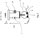
- FIG. 2 is a schematic representation of the compensation system.
- Supporting wheel 4 follows support path 6 as the vehicle travels along floor 2.
- Sensor 8 measures the height difference ⁇ Z FL of the surface of floor 2.
- the distance Z act between wheel 4 and chassis 3 is adjustable by means of compensation means 7.
- the goal is to avoid vertical movement of the chassis, that is, to keep Z ch unchanged.
- the vehicle has a traveling speed ⁇ (t) (m/s).
- sensor 8 provides a signal corresponding to, or convertible to, the derivative of Z FL , that is, the slope of supporting path at supporting location 5.
- This slope expressed for example as the change in Z FL (mm) per distance traveled (mm) along supporting path 6 is a dimensionless number.
- Multiplication of the slope with ⁇ (t) yields surface speed V FL .
- the surface speed can be considered the vertical speed imparted to supporting wheel by floor surface 6.
- V PL is the kinematic effect exerted on supporting wheel 4 by traveling surface 6.
- V FL is the same as that of the slope when ⁇ (t) has a positive sign.
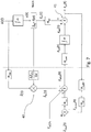
- Figure 3 shows a block diagram of the control circuit.
- Input parameters are Z FL and ⁇ (t).
- ⁇ Z FL is determined as explained above.
- the traveling speed of the vehicle ⁇ (t) can be determined by any suitable means, such as the speed of rotation of one of the (driven) wheels, etc.
- the first derivative of Z FL is multiplied by ⁇ (t) to yield surface speed V FL . Sign inversion yields V act,d .
- Power is supplied to compensation means 7 to generate the desired V act,d .
- compensation means 7 is controlled so as to produce a desired speed, as distinguished from generating a desired force, for example. This is particularly important in the context of industrial vehicles such as fork lift trucks, which may carry loads of considerably varying weights, or no load at all.
- the control mechanism for compensation means 7 contains a feedback loop that compares the obtained speed (V act ) with the desired speed (V act,d ), and allows for the power supplied to compensation means 7 to be adjusted until the desired speed is obtained. In this manner the control mechanism automatically adjusts for weight differences resulting from the presence or absence of a load.
- Block H MF in Figure 3 denotes a transfer function for the optional presence of a mechanical low pass filter.
- a mechanical low pass filter can be provided in the form of a degree of elasticity of supporting wheel 4.
- Such elasticity may be provided in the form of a wheel construction from a slightly elastic material, provision of a rubber bushing around the axis of wheel 4, a rubber ring around the circumference of wheel 4, and other such measures known in the art.
- wheel 4 can be considered perfectly rigid the value of transfer function H MP can be put at 1; if wheel 4 has elastic properties the value of H MF is less than 1 at higher frequency values (e.g. 10 Hz and up). The actual value can be determined experimentally, and pre-programmed into the control software depicted by Figure 3 .
- Block H meas denotes an absolute level measurement, such as a construction laser and a precision measuring laser detector. A persistent deviation from level is fed to block H v,act as a correction of the calculated V act.d .
- a precision measuring laser detector is highly accurate, but relatively slow.
- the feedback loop of Figure 3 may operate at a frequency on the order of 0.1 Hz, whereas the control circuit may operate at a frequency of 5 Hz or higher.
- a frequency of 0.1 Hz may be high enough for the control circuit.
- a precision measuring laser detector could be used for the control circuit.
- a constant velocity drift can be observed as the average misalignment with respect to the horizontal reference measured by an electronic carpenter's level.
- Figure 4 shows an alternate suspension for supporting wheel 4.
- the compensation means 7 supports the weight of the chassis (including any loads).
- the weight is curried by spring 22, reducing the task of compensation means 7 to providing the kinematic effects for counteracting the kinematic effects of supporting path 6.
- the compensation means of Figure 4 can be much lighter than that of Figure 2 .
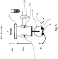
- Figure 5 shows an arrangement similar to that of Figure 4 , except that coil spring 22 is replaced with pneumatic spring 23.
- pneumatic spring a hydraulic spring or equivalent construction can be used.
- Figures 2 , 4 and 5 also show an arrangement to block the compensation means in case of catastrophic failure.
- Mechanical clamping device 24 creates a fixed connection between wheel 4 and chassis 3 when activated.
- Valve 25 blocks the oil flow of a hydropneumatic spring element 23 when activated and fixes in this way wheel 4 to chassis 3.
- Figure 6C shows a method for determining the second derivative of f(x).
- the system of figure 6C has a third sensor, located for example below the axis of wheel 4.
- the signals of the three sensors can be used to calculate ⁇ 2 Z FL /Ax 2 , which is an approximation of f"(x).
- Figure 7 is a schematic diagram of an embodiment of the invention.
- the diagram relates to a vehicle having one wheel equipped with a measuring system and an actuator.
- the vehicle may have additional wheels.
- the vehicle may be a fork lift or a very narrow aisle truck having three wheels or four wheels. In this example, only one of the wheels is provided with pitch and/or roll compensation.
- Input variables are the speed of the vehicle which is the first derivative of the vehicle's position along the travel path, ⁇ (t); and the slope of the floor surface ⁇ Z PL / ⁇ x, which can be measured as explained with reference to Figure 6B .
- Transfer function H VM represents any inaccuracies in the determination of vehicle speed x(t).
- the two input variables are multiplied with each other to yield the estimated surface speed z ⁇ ⁇ FL t .
- This surface speed can conceptually be seen as a kinematic effect (speed) being exerted on the supporting wheel.
- the sign of the surface speed is invented to yield (after correction by the feedback loop explained below) an actuator desired speed ⁇ act,d (t).
- a controller controls power provided to an actuator such that the actuator develops speed ⁇ act (t).
- the actuator speed is equal to (disregarding any corrections resulting from the feedback loop) but opposite in sign to the estimated surface speed z ⁇ ⁇ FL t .
- the feedback loop contains a measuring device providing a position measurement relative to a frame of reference that is external to the vehicle.
- a measuring device providing a position measurement relative to a frame of reference that is external to the vehicle.
- this can be an absolute height measurement system, for example comprising a construction laser and a precision measuring laser detector.
- an inclinometer can be used, which conceptually is an electronic carpenter's level.
- the inclinometer provides a signal that represents the tilt of the chassis relative to a virtual horizontal plane.
- the time average of the inclinometer reading should be zero, that is, over time the average position of the chassis should be horizontal.
- Transfer function H ZF filters out high frequency vibrations, for example vibrations having a frequency greater than 0.5 Hz.
- Figure 9 describes an embodiment having two wheels sharing an axis, wherein both wheels are provided with sensors for detecting surface imperfections, and only one wheel (wheel 1) having a compensation mechanism, such as an actuator.
- This embodiment is particularly suited for compensating roll movements of a traveling vehicle.
- Figure 9A is a diagrammatic representation of the control mechanism.
- the portion of Figure 9A above the dotted line represents the feed forward portion of the control mechanism.
- Input parameters are ⁇ (t) (the travel speed of the vehicle);
- Roll movement is caused by a difference between Z' 1 and Z' 2 .
- Figure 9B is a schematic representation of this truck, showing wheel 1 supported by track 1, wheel 2 supported by track 2. Track width L w , and the actuator associated with wheel 1.
- Figure 9C shows the truck of Figure 9B with wheel 1 encountering a bump, causing the actuator to retract.
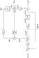
- Figure 10 is a diagrammatic representation of the control mechanism of a vehicle having two wheels provided with sensors and an actuator. This vehicle is similar to that of Figure 9 , but is different in that the second wheel also has an actuator.
- the compensation mechanisms of wheel 1 and wheel 2 operate independently from each other, each compensating for surface irregularities encountered in its respective travel path.
- the feedback mechanism comprises an inclinometer, which is used to determine any deviations from the desired roll angel of zero.
- the correction signal is split evenly between the two actuators, with opposite signs.
- this embodiment is particularly suited for compensating roll movements, but can also partially compensate pitch movements.
- the embodiment of Figure 11 has a feedback loop to correct for drift.
- This feedback loop comprises an inclinometer, which reports a pitch angle ⁇ pitch,ch .
- This value is compared to the desired pitch angle ⁇ pitch,ch,d , which typically is equal to zero. Any deviation is converted to a pitch angle velocity (rad/s), which is converted to a pitch velocity by multiplication with the wheel base L WB , i.e., the distance between the axis of the third wheel and the axis shared by the first and second wheels.
- the outcome is used to correct the signals to the actuators of the first and second wheels.
- no sign inversion is applied in this case.
- the invention also provides for a learning strategy to estimate some of these inaccuracies.
- a constant velocity drift can be observed as the average position error over time when implementing a proportional feedback control strategy as transfer function H CP .
- Compensating the drift velocity by the estimated average drift velocity has the advantage that the position error of the controlled system is substantially smaller. Applying this strategy repeatedly over time ensures that the drift is optimally compensated over time and yields a good average position (height) accuracy.
- FIG 12 presents the simplified scheme of the controlled system.
- V err (t) represents a velocity disturbance signal
- K P is the proportional feedback controller
- z(t) is the controlled position signal (chassis height or actuator position).
- the steady state velocity disturbance or constant velocity drift is calculated as the observed position error multiplied by the proportional feedback constant.
- This calculated velocity disturbance can be integrated in the control scheme of figure 7 as V offs .
- a constant velocity drift can be observed as the average misalignment with respect to the horizontal reference measured by an electronic carpenter's level.
- the inclinometer reading can be used to compensate any chassis tilt at standstill.
- a wheel actuator is used to put the chassis of the vehicle in a horizontal position when the vehicle is standing still.
- the controller can be programmed to anticipate standstill. For example, when the speed is below a predetermined threshold value, and the vehicle is decelerating, the controller selects a compensation protocol for leveling the chassis, whereas at speeds above the predetermined threshold value the controller selects a protocol for compensating roll and/or pitch.
- the inclinometer may be employed in a feedback loop, as described above.
- the two different protocols can be selected, for example, by adjusting the control parameters H CP and/or the filter parameters H IF
Claims (15)
- Un véhicule (1) comprenant un châssis (3) ; au moins une roue (4) en contact avec une surface de déplacement (2) ; caractérisé en ce que le véhicule (1) comprend en outre un moyen de détection (8) pour détecter une caractéristique de surface de la surface de déplacement (2) ; un moyen de traitement de données pour calculer, à partir de la caractéristique de surface, un premier effet cinématique exercé ou sur le point d'être exercé sur l'au moins une roue (4) par la surface de déplacement (2) ; un actionneur (7) pour exercer un deuxième effet cinématique sur l'au moins une roue (4), ledit deuxième effet cinématique étant conçu pour neutraliser le premier effet cinématique.
- Le véhicule (1) selon la revendication 1, comprenant en outre un moyen pour déterminer une vitesse de déplacement du véhicule (1), et dans lequel le moyen de traitement de données utilise la vitesse de déplacement du véhicule (1) pour calculer le premier effet cinématique.
- Le véhicule (1) selon la revendication 1 ou 2, dans lequel le premier effet cinématique est une vélocité ou une composante verticale d'une vélocité.
- Le véhicule (1) selon la revendication 1 ou 2, dans lequel le premier effet cinématique est une accélération ou une composante verticale d'une accélération.
- Le véhicule (1) selon l'une quelconque des revendications précédentes, dans lequel la caractéristique de surface est une première dérivée d'un profil vertical de la surface de déplacement (2).
- Le véhicule (1) selon l'une quelconque des revendications 1 à 4, dans lequel la caractéristique de surface est une deuxième dérivée d'un profil vertical de la surface de déplacement (2).
- Le véhicule (1) selon l'une quelconque des revendications précédentes, dans lequel le deuxième effet cinématique est égal ou approximativement égal, et de signe opposé, au premier effet cinématique.
- Le véhicule (1) selon l'une quelconque des revendications précédentes, comprenant en outre un mécanisme de rétroaction pour corriger des erreurs systématiques dans le premier effet cinématique.
- Le véhicule (1) selon la revendication 8, dans lequel le mécanisme de rétroaction comprend une mesure relative à une référence externe au véhicule (1).
- Le véhicule (1) selon l'une quelconque des revendications précédentes, comprenant une deuxième roue en contact avec la surface de déplacement (2), et un deuxième moyen de détection pour détecter une caractéristique de surface associée à la surface de déplacement (2), ledit deuxième moyen de détection étant associé à ladite deuxième roue.
- Le véhicule (1) selon la revendication 10, comprenant en outre un deuxième actionneur agissant sur ladite deuxième roue.
- Le véhicule (1) selon la revendication 10 ou 11, dans lequel la première roue (4) et la deuxième roue ont un axe commun.
- Le véhicule (1) selon l'une quelconque des revendications 10 à 12, comprenant une troisième roue en contact avec la surface de déplacement (2), et un troisième moyen de détection pour détecter une caractéristique de surface associée à la surface de déplacement (2), ledit troisième moyen de détection étant associé à ladite troisième roue.
- Le véhicule (1) selon la revendication 13, dans lequel la première roue (4) et la deuxième roue ont un axe commun, et la troisième roue a un axe différent de l'axe commun.
- Le véhicule (1) selon l'une quelconque des revendications précédentes, comprenant en outre un mécanisme de sécurité pour primer l'actionneur (7) ou des actionneurs (7).
Priority Applications (1)
| Application Number | Priority Date | Filing Date | Title |
|---|---|---|---|
| EP13709057.7A EP2814677B1 (fr) | 2012-02-15 | 2013-02-15 | Dispositif pour éviter le mouvement de roulis et de tangage d'un véhicule industriel |
Applications Claiming Priority (3)
| Application Number | Priority Date | Filing Date | Title |
|---|---|---|---|
| EP12155657 | 2012-02-15 | ||
| PCT/EP2013/053129 WO2013121022A1 (fr) | 2012-02-15 | 2013-02-15 | Système de réduction de roulement et de pas dans un véhicule mobile |
| EP13709057.7A EP2814677B1 (fr) | 2012-02-15 | 2013-02-15 | Dispositif pour éviter le mouvement de roulis et de tangage d'un véhicule industriel |
Publications (2)
| Publication Number | Publication Date |
|---|---|
| EP2814677A1 EP2814677A1 (fr) | 2014-12-24 |
| EP2814677B1 true EP2814677B1 (fr) | 2017-01-11 |
Family
ID=47877997
Family Applications (1)
| Application Number | Title | Priority Date | Filing Date |
|---|---|---|---|
| EP13709057.7A Active EP2814677B1 (fr) | 2012-02-15 | 2013-02-15 | Dispositif pour éviter le mouvement de roulis et de tangage d'un véhicule industriel |
Country Status (4)
| Country | Link |
|---|---|
| US (1) | US9463678B2 (fr) |
| EP (1) | EP2814677B1 (fr) |
| DE (1) | DE202013103503U1 (fr) |
| WO (1) | WO2013121022A1 (fr) |
Families Citing this family (7)
| Publication number | Priority date | Publication date | Assignee | Title |
|---|---|---|---|---|
| DE102012106626B3 (de) | 2012-07-20 | 2013-09-26 | Krauss-Maffei Wegmann Gmbh & Co. Kg | Waffenplattform, militärisches Fahrzeug mit einer Waffenplattform und Verfahren zum Betrieb einer Waffenplattform |
| DE102016119418A1 (de) | 2016-10-12 | 2018-04-12 | Kion Warehouse Systems Gmbh | Flurförderzeug |
| DE102016119417A1 (de) | 2016-10-12 | 2018-04-12 | Kion Warehouse Systems Gmbh | Flurförderzeug |
| US10569612B2 (en) * | 2017-12-11 | 2020-02-25 | Cnh Industrial America Llc | Suspension control system providing tire height corrections for an agricultural machine |
| US11364920B2 (en) * | 2018-05-01 | 2022-06-21 | Ford Global Technologies, Llc | Methods and apparatus to compensate for body roll in vehicle weight calculations |
| CN110716542A (zh) * | 2019-10-09 | 2020-01-21 | 重庆特斯联智慧科技股份有限公司 | 机器人移动控制方法及装置、电子设备及介质 |
| DE102020205606A1 (de) | 2020-05-04 | 2021-11-04 | Jungheinrich Aktiengesellschaft | Flurförderzeug |
Citations (2)
| Publication number | Priority date | Publication date | Assignee | Title |
|---|---|---|---|---|
| CN201696921U (zh) * | 2010-05-13 | 2011-01-05 | 深圳市旭翔光电科技有限公司 | Led照明灯泡 |
| KR101017349B1 (ko) * | 2009-12-03 | 2011-02-28 | 테크룩스 주식회사 | 벌브타입의 엘이디램프 |
Family Cites Families (39)
| Publication number | Priority date | Publication date | Assignee | Title |
|---|---|---|---|---|
| US3937339A (en) | 1971-10-29 | 1976-02-10 | Koehring Company | Vehicle having transverse leveling means |
| DE3930517A1 (de) | 1989-06-29 | 1991-01-10 | Bosch Gmbh Robert | Vorrichtung zur fahrbahnabhaengigen fahrwerksregelung |
| JP2541353B2 (ja) | 1990-09-18 | 1996-10-09 | 三菱自動車工業株式会社 | 車両用アクティブサスペンション装置 |
| JPH0624333A (ja) | 1992-04-17 | 1994-02-01 | Masuda Denki Kk | 遠隔制御管内歩行装置 |
| JPH0624233A (ja) | 1992-07-09 | 1994-02-01 | Nissan Motor Co Ltd | サスペンション制御装置 |
| EP1439372A1 (fr) * | 1996-11-25 | 2004-07-21 | Toyota Jidosha Kabushiki Kaisha | Dispositif de navigation pour véhicule et préparation de données de configuration de la route utilisées avec ce dispositif |
| US7195250B2 (en) | 2000-03-27 | 2007-03-27 | Bose Corporation | Surface vehicle vertical trajectory planning |
| US7109856B2 (en) * | 2000-09-25 | 2006-09-19 | Ford Global Technologies, Llc | Wheel lifted and grounded identification for an automotive vehicle |
| US6904350B2 (en) * | 2000-09-25 | 2005-06-07 | Ford Global Technologies, Llc | System for dynamically determining the wheel grounding and wheel lifting conditions and their applications in roll stability control |
| US7676307B2 (en) * | 2001-11-05 | 2010-03-09 | Ford Global Technologies | System and method for controlling a safety system of a vehicle in response to conditions sensed by tire sensors related applications |
| DE10157426A1 (de) | 2001-11-25 | 2003-06-12 | Joachim Broetz | Vorrichtung zur aktiven Fahrwerksregelung |
| US6804584B2 (en) * | 2002-03-20 | 2004-10-12 | Ford Global Technologies, Llc | Method for determining the roll angle of a vehicle using an estimation of road bank angle |
| DE60334877D1 (de) * | 2002-08-01 | 2010-12-23 | Ford Global Tech Llc | Radabhebeerkennung für ein Kraftfahrzeug mit passiver und aktiver Erkennung |
| US7079928B2 (en) * | 2002-08-01 | 2006-07-18 | Ford Global Technologies, Llc | System and method for determining a wheel departure angle for a rollover control system with respect to road roll rate and loading misalignment |
| EP1549462B1 (fr) | 2002-10-04 | 2009-11-18 | Alphaplan International | Dispositif pour niveler des sols |
| US7136731B2 (en) * | 2003-06-11 | 2006-11-14 | Ford Global Technologies, Llc | System for determining vehicular relative roll angle during a potential rollover event |
| DE10337006A1 (de) | 2003-08-12 | 2005-03-10 | Continental Ag | Verfahren und Vorrichtung zur Verbesserung des Fahrkomforts von Kraftfahrzeugen |
| US7647148B2 (en) * | 2003-12-12 | 2010-01-12 | Ford Global Technologies, Llc | Roll stability control system for an automotive vehicle using coordinated control of anti-roll bar and brakes |
| US7222007B2 (en) * | 2004-01-07 | 2007-05-22 | Ford Global Technologies, Llc | Attitude sensing system for an automotive vehicle relative to the road |
| US7401871B2 (en) * | 2004-03-18 | 2008-07-22 | Ford Global Technologies, Llc | Method of controlling an automotive vehicle having a trailer using rear axle slip angle |
| US7185855B2 (en) * | 2004-04-30 | 2007-03-06 | Honeywell International, Inc. | Method and system for steering a momentum control system |
| US7668645B2 (en) * | 2004-10-15 | 2010-02-23 | Ford Global Technologies | System and method for dynamically determining vehicle loading and vertical loading distance for use in a vehicle dynamic control system |
| FR2890901B1 (fr) * | 2005-09-22 | 2007-12-14 | Peugeot Citroen Automobiles Sa | Dispositif de commande de suspension, vehicule muni de celui-ci, procede d'obtention et programme. |
| FR2890904B1 (fr) * | 2005-09-22 | 2007-12-14 | Peugeot Citroen Automobiles Sa | Dispositif de commande de suspension, vehicule muni de celui-ci, procede d'obtention et programme |
| FR2890900B1 (fr) * | 2005-09-22 | 2007-12-14 | Peugeot Citroen Automobiles Sa | Dispositif de commande de suspension, vehicule muni de celui-ci, procede d'obtention et programme. |
| FR2890902B1 (fr) * | 2005-09-22 | 2007-12-14 | Peugeot Citroen Automobiles Sa | Dispositif de commande de suspension, vehicule muni de celui-ci, procede d'obtention et programme |
| FR2890903B1 (fr) * | 2005-09-22 | 2008-12-05 | Peugeot Citroen Automobiles Sa | Dispositif de commande de suspension, vehicule muni de celui-ci, procede d'obtention et programme. |
| DE102006001436B4 (de) | 2006-01-10 | 2009-08-13 | Zf Friedrichshafen Ag | Verfahren zum Bestimmen wenigstens eines Bewegungszustands eines Fahrzeugaufbaus |
| US7739014B2 (en) * | 2006-08-30 | 2010-06-15 | Ford Global Technolgies | Integrated control system for stability control of yaw, roll and lateral motion of a driving vehicle using an integrated sensing system to determine a final linear lateral velocity |
| US7970512B2 (en) * | 2006-08-30 | 2011-06-28 | Ford Global Technologies | Integrated control system for stability control of yaw, roll and lateral motion of a driving vehicle using an integrated sensing system with pitch information |
| US7885750B2 (en) * | 2006-08-30 | 2011-02-08 | Ford Global Technologies | Integrated control system for stability control of yaw, roll and lateral motion of a driving vehicle using an integrated sensing system to determine a sideslip angle |
| US8321088B2 (en) * | 2006-08-30 | 2012-11-27 | Ford Global Technologies | Integrated control system for stability control of yaw, roll and lateral motion of a driving vehicle using an integrated sensing system to determine lateral velocity |
| US8712639B2 (en) * | 2006-08-30 | 2014-04-29 | Ford Global Technologies | Integrated control system for stability control of yaw, roll and lateral motion of a driving vehicle using an integrated sensing system to determine longitudinal velocity |
| US8108104B2 (en) * | 2006-11-16 | 2012-01-31 | Ford Global Technologies, Llc | Tripped rollover mitigation and prevention systems and methods |
| US8032281B2 (en) * | 2007-03-29 | 2011-10-04 | Ford Global Technologies | Vehicle control system with advanced tire monitoring |
| JP4567034B2 (ja) * | 2007-08-08 | 2010-10-20 | 本田技研工業株式会社 | 減衰力可変ダンパの制御装置 |
| JP4968006B2 (ja) * | 2007-11-13 | 2012-07-04 | トヨタ自動車株式会社 | サスペンション制御装置 |
| CN102307739B (zh) * | 2009-02-16 | 2014-03-26 | 丰田自动车株式会社 | 车辆的稳定器控制装置 |
| US9702349B2 (en) * | 2013-03-15 | 2017-07-11 | ClearMotion, Inc. | Active vehicle suspension system |
-
2013
- 2013-02-15 WO PCT/EP2013/053129 patent/WO2013121022A1/fr active Application Filing
- 2013-02-15 DE DE202013103503U patent/DE202013103503U1/de not_active Expired - Lifetime
- 2013-02-15 EP EP13709057.7A patent/EP2814677B1/fr active Active
- 2013-02-15 US US14/373,987 patent/US9463678B2/en active Active
Patent Citations (2)
| Publication number | Priority date | Publication date | Assignee | Title |
|---|---|---|---|---|
| KR101017349B1 (ko) * | 2009-12-03 | 2011-02-28 | 테크룩스 주식회사 | 벌브타입의 엘이디램프 |
| CN201696921U (zh) * | 2010-05-13 | 2011-01-05 | 深圳市旭翔光电科技有限公司 | Led照明灯泡 |
Also Published As
| Publication number | Publication date |
|---|---|
| US9463678B2 (en) | 2016-10-11 |
| DE202013103503U1 (de) | 2013-08-28 |
| EP2814677A1 (fr) | 2014-12-24 |
| WO2013121022A1 (fr) | 2013-08-22 |
| US20150039184A1 (en) | 2015-02-05 |
Similar Documents
| Publication | Publication Date | Title |
|---|---|---|
| EP2814677B1 (fr) | Dispositif pour éviter le mouvement de roulis et de tangage d'un véhicule industriel | |
| JP5171594B2 (ja) | 電動車両及びそのピッチング制御装置 | |
| CN104045029B (zh) | 升降叉车系统 | |
| CN110872088B (zh) | 用于升降装卸车的动态稳定性确定系统 | |
| US8140228B2 (en) | System and method for dynamically maintaining the stability of a material handling vehicle having a vertical lift | |
| US20100023220A1 (en) | Vehicle and control method of the same | |
| US20060267296A1 (en) | Electronic control of vehicle air suspension | |
| US9302893B2 (en) | Vibration control systems and methods for industrial lift trucks | |
| CN107257747B (zh) | 用于补偿竖直运动的方法 | |
| US20140379198A1 (en) | Mobile Object | |
| EP2511111B1 (fr) | Dispositif de commande de véhicule | |
| US20210379954A1 (en) | Method and apparatus for operating suspension systems | |
| CN110901327A (zh) | 主动悬挂系统、自动导引运输车及其压力调节方法 | |
| JP5675405B2 (ja) | 軌道系交通車両及びその車体姿勢制御装置 | |
| JP5487252B2 (ja) | 電動車両及びそのピッチング制御装置 | |
| KR101410631B1 (ko) | 연료탱크를 이용한 차량 수평 유지장치 | |
| CN113374822A (zh) | 装卸车辆的振动抑制系统及装卸车辆 | |
| CN115023355A (zh) | 车辆系统的前瞻控制 | |
| JP2020029155A (ja) | 走行区間判別方法及び鉄道車両の走行制御方法 |
Legal Events
| Date | Code | Title | Description |
|---|---|---|---|
| PUAI | Public reference made under article 153(3) epc to a published international application that has entered the european phase |
Free format text: ORIGINAL CODE: 0009012 |
|
| 17P | Request for examination filed |
Effective date: 20140915 |
|
| AK | Designated contracting states |
Kind code of ref document: A1 Designated state(s): AL AT BE BG CH CY CZ DE DK EE ES FI FR GB GR HR HU IE IS IT LI LT LU LV MC MK MT NL NO PL PT RO RS SE SI SK SM TR |
|
| AX | Request for extension of the european patent |
Extension state: BA ME |
|
| DAX | Request for extension of the european patent (deleted) | ||
| 17Q | First examination report despatched |
Effective date: 20151103 |
|
| GRAP | Despatch of communication of intention to grant a patent |
Free format text: ORIGINAL CODE: EPIDOSNIGR1 |
|
| INTG | Intention to grant announced |
Effective date: 20160729 |
|
| RAP1 | Party data changed (applicant data changed or rights of an application transferred) |
Owner name: FLOOR MASTER |
|
| GRAS | Grant fee paid |
Free format text: ORIGINAL CODE: EPIDOSNIGR3 |
|
| STAA | Information on the status of an ep patent application or granted ep patent |
Free format text: STATUS: GRANT OF PATENT IS INTENDED |
|
| GRAA | (expected) grant |
Free format text: ORIGINAL CODE: 0009210 |
|
| STAA | Information on the status of an ep patent application or granted ep patent |
Free format text: STATUS: THE PATENT HAS BEEN GRANTED |
|
| AK | Designated contracting states |
Kind code of ref document: B1 Designated state(s): AL AT BE BG CH CY CZ DE DK EE ES FI FR GB GR HR HU IE IS IT LI LT LU LV MC MK MT NL NO PL PT RO RS SE SI SK SM TR |
|
| REG | Reference to a national code |
Ref country code: GB Ref legal event code: FG4D |
|
| REG | Reference to a national code |
Ref country code: CH Ref legal event code: EP |
|
| REG | Reference to a national code |
Ref country code: AT Ref legal event code: REF Ref document number: 860913 Country of ref document: AT Kind code of ref document: T Effective date: 20170115 |
|
| REG | Reference to a national code |
Ref country code: IE Ref legal event code: FG4D |
|
| REG | Reference to a national code |
Ref country code: FR Ref legal event code: PLFP Year of fee payment: 5 |
|
| REG | Reference to a national code |
Ref country code: DE Ref legal event code: R096 Ref document number: 602013016434 Country of ref document: DE |
|
| REG | Reference to a national code |
Ref country code: SE Ref legal event code: TRGR |
|
| REG | Reference to a national code |
Ref country code: LT Ref legal event code: MG4D |
|
| REG | Reference to a national code |
Ref country code: NL Ref legal event code: MP Effective date: 20170111 |
|
| PG25 | Lapsed in a contracting state [announced via postgrant information from national office to epo] |
Ref country code: BE Free format text: LAPSE BECAUSE OF NON-PAYMENT OF DUE FEES Effective date: 20170228 |
|
| REG | Reference to a national code |
Ref country code: AT Ref legal event code: MK05 Ref document number: 860913 Country of ref document: AT Kind code of ref document: T Effective date: 20170111 |
|
| PG25 | Lapsed in a contracting state [announced via postgrant information from national office to epo] |
Ref country code: NL Free format text: LAPSE BECAUSE OF FAILURE TO SUBMIT A TRANSLATION OF THE DESCRIPTION OR TO PAY THE FEE WITHIN THE PRESCRIBED TIME-LIMIT Effective date: 20170111 |
|
| PG25 | Lapsed in a contracting state [announced via postgrant information from national office to epo] |
Ref country code: HR Free format text: LAPSE BECAUSE OF FAILURE TO SUBMIT A TRANSLATION OF THE DESCRIPTION OR TO PAY THE FEE WITHIN THE PRESCRIBED TIME-LIMIT Effective date: 20170111 Ref country code: FI Free format text: LAPSE BECAUSE OF FAILURE TO SUBMIT A TRANSLATION OF THE DESCRIPTION OR TO PAY THE FEE WITHIN THE PRESCRIBED TIME-LIMIT Effective date: 20170111 Ref country code: LT Free format text: LAPSE BECAUSE OF FAILURE TO SUBMIT A TRANSLATION OF THE DESCRIPTION OR TO PAY THE FEE WITHIN THE PRESCRIBED TIME-LIMIT Effective date: 20170111 Ref country code: GR Free format text: LAPSE BECAUSE OF FAILURE TO SUBMIT A TRANSLATION OF THE DESCRIPTION OR TO PAY THE FEE WITHIN THE PRESCRIBED TIME-LIMIT Effective date: 20170412 Ref country code: NO Free format text: LAPSE BECAUSE OF FAILURE TO SUBMIT A TRANSLATION OF THE DESCRIPTION OR TO PAY THE FEE WITHIN THE PRESCRIBED TIME-LIMIT Effective date: 20170411 Ref country code: IS Free format text: LAPSE BECAUSE OF FAILURE TO SUBMIT A TRANSLATION OF THE DESCRIPTION OR TO PAY THE FEE WITHIN THE PRESCRIBED TIME-LIMIT Effective date: 20170511 |
|
| PG25 | Lapsed in a contracting state [announced via postgrant information from national office to epo] |
Ref country code: RS Free format text: LAPSE BECAUSE OF FAILURE TO SUBMIT A TRANSLATION OF THE DESCRIPTION OR TO PAY THE FEE WITHIN THE PRESCRIBED TIME-LIMIT Effective date: 20170111 Ref country code: AT Free format text: LAPSE BECAUSE OF FAILURE TO SUBMIT A TRANSLATION OF THE DESCRIPTION OR TO PAY THE FEE WITHIN THE PRESCRIBED TIME-LIMIT Effective date: 20170111 Ref country code: PL Free format text: LAPSE BECAUSE OF FAILURE TO SUBMIT A TRANSLATION OF THE DESCRIPTION OR TO PAY THE FEE WITHIN THE PRESCRIBED TIME-LIMIT Effective date: 20170111 Ref country code: BG Free format text: LAPSE BECAUSE OF FAILURE TO SUBMIT A TRANSLATION OF THE DESCRIPTION OR TO PAY THE FEE WITHIN THE PRESCRIBED TIME-LIMIT Effective date: 20170411 Ref country code: ES Free format text: LAPSE BECAUSE OF FAILURE TO SUBMIT A TRANSLATION OF THE DESCRIPTION OR TO PAY THE FEE WITHIN THE PRESCRIBED TIME-LIMIT Effective date: 20170111 Ref country code: PT Free format text: LAPSE BECAUSE OF FAILURE TO SUBMIT A TRANSLATION OF THE DESCRIPTION OR TO PAY THE FEE WITHIN THE PRESCRIBED TIME-LIMIT Effective date: 20170511 Ref country code: LV Free format text: LAPSE BECAUSE OF FAILURE TO SUBMIT A TRANSLATION OF THE DESCRIPTION OR TO PAY THE FEE WITHIN THE PRESCRIBED TIME-LIMIT Effective date: 20170111 |
|
| REG | Reference to a national code |
Ref country code: CH Ref legal event code: PL |
|
| REG | Reference to a national code |
Ref country code: DE Ref legal event code: R097 Ref document number: 602013016434 Country of ref document: DE |
|
| PG25 | Lapsed in a contracting state [announced via postgrant information from national office to epo] |
Ref country code: CH Free format text: LAPSE BECAUSE OF NON-PAYMENT OF DUE FEES Effective date: 20170228 Ref country code: RO Free format text: LAPSE BECAUSE OF FAILURE TO SUBMIT A TRANSLATION OF THE DESCRIPTION OR TO PAY THE FEE WITHIN THE PRESCRIBED TIME-LIMIT Effective date: 20170111 Ref country code: CZ Free format text: LAPSE BECAUSE OF FAILURE TO SUBMIT A TRANSLATION OF THE DESCRIPTION OR TO PAY THE FEE WITHIN THE PRESCRIBED TIME-LIMIT Effective date: 20170111 Ref country code: SK Free format text: LAPSE BECAUSE OF FAILURE TO SUBMIT A TRANSLATION OF THE DESCRIPTION OR TO PAY THE FEE WITHIN THE PRESCRIBED TIME-LIMIT Effective date: 20170111 Ref country code: LI Free format text: LAPSE BECAUSE OF NON-PAYMENT OF DUE FEES Effective date: 20170228 Ref country code: EE Free format text: LAPSE BECAUSE OF FAILURE TO SUBMIT A TRANSLATION OF THE DESCRIPTION OR TO PAY THE FEE WITHIN THE PRESCRIBED TIME-LIMIT Effective date: 20170111 |
|
| PLBE | No opposition filed within time limit |
Free format text: ORIGINAL CODE: 0009261 |
|
| STAA | Information on the status of an ep patent application or granted ep patent |
Free format text: STATUS: NO OPPOSITION FILED WITHIN TIME LIMIT |
|
| REG | Reference to a national code |
Ref country code: IE Ref legal event code: MM4A |
|
| PG25 | Lapsed in a contracting state [announced via postgrant information from national office to epo] |
Ref country code: MC Free format text: LAPSE BECAUSE OF FAILURE TO SUBMIT A TRANSLATION OF THE DESCRIPTION OR TO PAY THE FEE WITHIN THE PRESCRIBED TIME-LIMIT Effective date: 20170111 Ref country code: SM Free format text: LAPSE BECAUSE OF FAILURE TO SUBMIT A TRANSLATION OF THE DESCRIPTION OR TO PAY THE FEE WITHIN THE PRESCRIBED TIME-LIMIT Effective date: 20170111 Ref country code: DK Free format text: LAPSE BECAUSE OF FAILURE TO SUBMIT A TRANSLATION OF THE DESCRIPTION OR TO PAY THE FEE WITHIN THE PRESCRIBED TIME-LIMIT Effective date: 20170111 |
|
| 26N | No opposition filed |
Effective date: 20171012 |
|
| PG25 | Lapsed in a contracting state [announced via postgrant information from national office to epo] |
Ref country code: LU Free format text: LAPSE BECAUSE OF NON-PAYMENT OF DUE FEES Effective date: 20170215 |
|
| REG | Reference to a national code |
Ref country code: FR Ref legal event code: PLFP Year of fee payment: 6 |
|
| REG | Reference to a national code |
Ref country code: BE Ref legal event code: MM Effective date: 20170228 |
|
| PG25 | Lapsed in a contracting state [announced via postgrant information from national office to epo] |
Ref country code: SI Free format text: LAPSE BECAUSE OF FAILURE TO SUBMIT A TRANSLATION OF THE DESCRIPTION OR TO PAY THE FEE WITHIN THE PRESCRIBED TIME-LIMIT Effective date: 20170111 Ref country code: IE Free format text: LAPSE BECAUSE OF NON-PAYMENT OF DUE FEES Effective date: 20170215 |
|
| REG | Reference to a national code |
Ref country code: FR Ref legal event code: CA Effective date: 20180619 |
|
| PG25 | Lapsed in a contracting state [announced via postgrant information from national office to epo] |
Ref country code: MT Free format text: LAPSE BECAUSE OF NON-PAYMENT OF DUE FEES Effective date: 20170215 |
|
| PG25 | Lapsed in a contracting state [announced via postgrant information from national office to epo] |
Ref country code: HU Free format text: LAPSE BECAUSE OF FAILURE TO SUBMIT A TRANSLATION OF THE DESCRIPTION OR TO PAY THE FEE WITHIN THE PRESCRIBED TIME-LIMIT; INVALID AB INITIO Effective date: 20130215 |
|
| PG25 | Lapsed in a contracting state [announced via postgrant information from national office to epo] |
Ref country code: CY Free format text: LAPSE BECAUSE OF FAILURE TO SUBMIT A TRANSLATION OF THE DESCRIPTION OR TO PAY THE FEE WITHIN THE PRESCRIBED TIME-LIMIT Effective date: 20170111 |
|
| PG25 | Lapsed in a contracting state [announced via postgrant information from national office to epo] |
Ref country code: MK Free format text: LAPSE BECAUSE OF FAILURE TO SUBMIT A TRANSLATION OF THE DESCRIPTION OR TO PAY THE FEE WITHIN THE PRESCRIBED TIME-LIMIT Effective date: 20170111 |
|
| PG25 | Lapsed in a contracting state [announced via postgrant information from national office to epo] |
Ref country code: TR Free format text: LAPSE BECAUSE OF FAILURE TO SUBMIT A TRANSLATION OF THE DESCRIPTION OR TO PAY THE FEE WITHIN THE PRESCRIBED TIME-LIMIT Effective date: 20170111 |
|
| PG25 | Lapsed in a contracting state [announced via postgrant information from national office to epo] |
Ref country code: AL Free format text: LAPSE BECAUSE OF FAILURE TO SUBMIT A TRANSLATION OF THE DESCRIPTION OR TO PAY THE FEE WITHIN THE PRESCRIBED TIME-LIMIT Effective date: 20170111 |
|
| PGFP | Annual fee paid to national office [announced via postgrant information from national office to epo] |
Ref country code: SE Payment date: 20230223 Year of fee payment: 11 Ref country code: IT Payment date: 20230223 Year of fee payment: 11 Ref country code: GB Payment date: 20230223 Year of fee payment: 11 Ref country code: DE Payment date: 20230227 Year of fee payment: 11 |
|
| P01 | Opt-out of the competence of the unified patent court (upc) registered |
Effective date: 20230527 |
|
| PGFP | Annual fee paid to national office [announced via postgrant information from national office to epo] |
Ref country code: FR Payment date: 20231220 Year of fee payment: 12 |