EP2814103B1 - Ensemble électrode et cellule de batterie secondaire polymère comprenant celui-ci - Google Patents
Ensemble électrode et cellule de batterie secondaire polymère comprenant celui-ci Download PDFInfo
- Publication number
- EP2814103B1 EP2814103B1 EP14752035.7A EP14752035A EP2814103B1 EP 2814103 B1 EP2814103 B1 EP 2814103B1 EP 14752035 A EP14752035 A EP 14752035A EP 2814103 B1 EP2814103 B1 EP 2814103B1
- Authority
- EP
- European Patent Office
- Prior art keywords
- separator
- electrode
- radical
- unit
- auxiliary unit
- Prior art date
- Legal status (The legal status is an assumption and is not a legal conclusion. Google has not performed a legal analysis and makes no representation as to the accuracy of the status listed.)
- Active
Links
Images


Classifications
-
- H—ELECTRICITY
- H01—ELECTRIC ELEMENTS
- H01M—PROCESSES OR MEANS, e.g. BATTERIES, FOR THE DIRECT CONVERSION OF CHEMICAL ENERGY INTO ELECTRICAL ENERGY
- H01M50/00—Constructional details or processes of manufacture of the non-active parts of electrochemical cells other than fuel cells, e.g. hybrid cells
- H01M50/50—Current conducting connections for cells or batteries
- H01M50/528—Fixed electrical connections, i.e. not intended for disconnection
- H01M50/529—Intercell connections through partitions, e.g. in a battery casing
-
- H—ELECTRICITY
- H01—ELECTRIC ELEMENTS
- H01M—PROCESSES OR MEANS, e.g. BATTERIES, FOR THE DIRECT CONVERSION OF CHEMICAL ENERGY INTO ELECTRICAL ENERGY
- H01M10/00—Secondary cells; Manufacture thereof
- H01M10/04—Construction or manufacture in general
- H01M10/0413—Large-sized flat cells or batteries for motive or stationary systems with plate-like electrodes
-
- H—ELECTRICITY
- H01—ELECTRIC ELEMENTS
- H01M—PROCESSES OR MEANS, e.g. BATTERIES, FOR THE DIRECT CONVERSION OF CHEMICAL ENERGY INTO ELECTRICAL ENERGY
- H01M10/00—Secondary cells; Manufacture thereof
- H01M10/04—Construction or manufacture in general
- H01M10/0436—Small-sized flat cells or batteries for portable equipment
-
- H—ELECTRICITY
- H01—ELECTRIC ELEMENTS
- H01M—PROCESSES OR MEANS, e.g. BATTERIES, FOR THE DIRECT CONVERSION OF CHEMICAL ENERGY INTO ELECTRICAL ENERGY
- H01M10/00—Secondary cells; Manufacture thereof
- H01M10/04—Construction or manufacture in general
- H01M10/0468—Compression means for stacks of electrodes and separators
-
- H—ELECTRICITY
- H01—ELECTRIC ELEMENTS
- H01M—PROCESSES OR MEANS, e.g. BATTERIES, FOR THE DIRECT CONVERSION OF CHEMICAL ENERGY INTO ELECTRICAL ENERGY
- H01M10/00—Secondary cells; Manufacture thereof
- H01M10/05—Accumulators with non-aqueous electrolyte
- H01M10/056—Accumulators with non-aqueous electrolyte characterised by the materials used as electrolytes, e.g. mixed inorganic/organic electrolytes
- H01M10/0564—Accumulators with non-aqueous electrolyte characterised by the materials used as electrolytes, e.g. mixed inorganic/organic electrolytes the electrolyte being constituted of organic materials only
- H01M10/0565—Polymeric materials, e.g. gel-type or solid-type
-
- H—ELECTRICITY
- H01—ELECTRIC ELEMENTS
- H01M—PROCESSES OR MEANS, e.g. BATTERIES, FOR THE DIRECT CONVERSION OF CHEMICAL ENERGY INTO ELECTRICAL ENERGY
- H01M10/00—Secondary cells; Manufacture thereof
- H01M10/05—Accumulators with non-aqueous electrolyte
- H01M10/058—Construction or manufacture
- H01M10/0585—Construction or manufacture of accumulators having only flat construction elements, i.e. flat positive electrodes, flat negative electrodes and flat separators
-
- H—ELECTRICITY
- H01—ELECTRIC ELEMENTS
- H01M—PROCESSES OR MEANS, e.g. BATTERIES, FOR THE DIRECT CONVERSION OF CHEMICAL ENERGY INTO ELECTRICAL ENERGY
- H01M10/00—Secondary cells; Manufacture thereof
- H01M10/60—Heating or cooling; Temperature control
- H01M10/61—Types of temperature control
- H01M10/615—Heating or keeping warm
-
- H—ELECTRICITY
- H01—ELECTRIC ELEMENTS
- H01M—PROCESSES OR MEANS, e.g. BATTERIES, FOR THE DIRECT CONVERSION OF CHEMICAL ENERGY INTO ELECTRICAL ENERGY
- H01M4/00—Electrodes
- H01M4/02—Electrodes composed of, or comprising, active material
- H01M4/04—Processes of manufacture in general
- H01M4/0471—Processes of manufacture in general involving thermal treatment, e.g. firing, sintering, backing particulate active material, thermal decomposition, pyrolysis
-
- H—ELECTRICITY
- H01—ELECTRIC ELEMENTS
- H01M—PROCESSES OR MEANS, e.g. BATTERIES, FOR THE DIRECT CONVERSION OF CHEMICAL ENERGY INTO ELECTRICAL ENERGY
- H01M4/00—Electrodes
- H01M4/02—Electrodes composed of, or comprising, active material
- H01M4/13—Electrodes for accumulators with non-aqueous electrolyte, e.g. for lithium-accumulators; Processes of manufacture thereof
-
- H—ELECTRICITY
- H01—ELECTRIC ELEMENTS
- H01M—PROCESSES OR MEANS, e.g. BATTERIES, FOR THE DIRECT CONVERSION OF CHEMICAL ENERGY INTO ELECTRICAL ENERGY
- H01M50/00—Constructional details or processes of manufacture of the non-active parts of electrochemical cells other than fuel cells, e.g. hybrid cells
- H01M50/10—Primary casings, jackets or wrappings of a single cell or a single battery
- H01M50/102—Primary casings, jackets or wrappings of a single cell or a single battery characterised by their shape or physical structure
- H01M50/105—Pouches or flexible bags
-
- H—ELECTRICITY
- H01—ELECTRIC ELEMENTS
- H01M—PROCESSES OR MEANS, e.g. BATTERIES, FOR THE DIRECT CONVERSION OF CHEMICAL ENERGY INTO ELECTRICAL ENERGY
- H01M50/00—Constructional details or processes of manufacture of the non-active parts of electrochemical cells other than fuel cells, e.g. hybrid cells
- H01M50/40—Separators; Membranes; Diaphragms; Spacing elements inside cells
- H01M50/409—Separators, membranes or diaphragms characterised by the material
- H01M50/431—Inorganic material
-
- H—ELECTRICITY
- H01—ELECTRIC ELEMENTS
- H01M—PROCESSES OR MEANS, e.g. BATTERIES, FOR THE DIRECT CONVERSION OF CHEMICAL ENERGY INTO ELECTRICAL ENERGY
- H01M50/00—Constructional details or processes of manufacture of the non-active parts of electrochemical cells other than fuel cells, e.g. hybrid cells
- H01M50/40—Separators; Membranes; Diaphragms; Spacing elements inside cells
- H01M50/409—Separators, membranes or diaphragms characterised by the material
- H01M50/446—Composite material consisting of a mixture of organic and inorganic materials
-
- H—ELECTRICITY
- H01—ELECTRIC ELEMENTS
- H01M—PROCESSES OR MEANS, e.g. BATTERIES, FOR THE DIRECT CONVERSION OF CHEMICAL ENERGY INTO ELECTRICAL ENERGY
- H01M50/00—Constructional details or processes of manufacture of the non-active parts of electrochemical cells other than fuel cells, e.g. hybrid cells
- H01M50/40—Separators; Membranes; Diaphragms; Spacing elements inside cells
- H01M50/409—Separators, membranes or diaphragms characterised by the material
- H01M50/449—Separators, membranes or diaphragms characterised by the material having a layered structure
-
- H—ELECTRICITY
- H01—ELECTRIC ELEMENTS
- H01M—PROCESSES OR MEANS, e.g. BATTERIES, FOR THE DIRECT CONVERSION OF CHEMICAL ENERGY INTO ELECTRICAL ENERGY
- H01M50/00—Constructional details or processes of manufacture of the non-active parts of electrochemical cells other than fuel cells, e.g. hybrid cells
- H01M50/40—Separators; Membranes; Diaphragms; Spacing elements inside cells
- H01M50/46—Separators, membranes or diaphragms characterised by their combination with electrodes
-
- H—ELECTRICITY
- H01—ELECTRIC ELEMENTS
- H01M—PROCESSES OR MEANS, e.g. BATTERIES, FOR THE DIRECT CONVERSION OF CHEMICAL ENERGY INTO ELECTRICAL ENERGY
- H01M50/00—Constructional details or processes of manufacture of the non-active parts of electrochemical cells other than fuel cells, e.g. hybrid cells
- H01M50/40—Separators; Membranes; Diaphragms; Spacing elements inside cells
- H01M50/463—Separators, membranes or diaphragms characterised by their shape
-
- H—ELECTRICITY
- H01—ELECTRIC ELEMENTS
- H01M—PROCESSES OR MEANS, e.g. BATTERIES, FOR THE DIRECT CONVERSION OF CHEMICAL ENERGY INTO ELECTRICAL ENERGY
- H01M50/00—Constructional details or processes of manufacture of the non-active parts of electrochemical cells other than fuel cells, e.g. hybrid cells
- H01M50/40—Separators; Membranes; Diaphragms; Spacing elements inside cells
- H01M50/489—Separators, membranes, diaphragms or spacing elements inside the cells, characterised by their physical properties, e.g. swelling degree, hydrophilicity or shut down properties
- H01M50/491—Porosity
-
- H—ELECTRICITY
- H01—ELECTRIC ELEMENTS
- H01M—PROCESSES OR MEANS, e.g. BATTERIES, FOR THE DIRECT CONVERSION OF CHEMICAL ENERGY INTO ELECTRICAL ENERGY
- H01M2300/00—Electrolytes
- H01M2300/0017—Non-aqueous electrolytes
- H01M2300/0065—Solid electrolytes
- H01M2300/0082—Organic polymers
-
- Y—GENERAL TAGGING OF NEW TECHNOLOGICAL DEVELOPMENTS; GENERAL TAGGING OF CROSS-SECTIONAL TECHNOLOGIES SPANNING OVER SEVERAL SECTIONS OF THE IPC; TECHNICAL SUBJECTS COVERED BY FORMER USPC CROSS-REFERENCE ART COLLECTIONS [XRACs] AND DIGESTS
- Y02—TECHNOLOGIES OR APPLICATIONS FOR MITIGATION OR ADAPTATION AGAINST CLIMATE CHANGE
- Y02E—REDUCTION OF GREENHOUSE GAS [GHG] EMISSIONS, RELATED TO ENERGY GENERATION, TRANSMISSION OR DISTRIBUTION
- Y02E60/00—Enabling technologies; Technologies with a potential or indirect contribution to GHG emissions mitigation
- Y02E60/10—Energy storage using batteries
-
- Y—GENERAL TAGGING OF NEW TECHNOLOGICAL DEVELOPMENTS; GENERAL TAGGING OF CROSS-SECTIONAL TECHNOLOGIES SPANNING OVER SEVERAL SECTIONS OF THE IPC; TECHNICAL SUBJECTS COVERED BY FORMER USPC CROSS-REFERENCE ART COLLECTIONS [XRACs] AND DIGESTS
- Y02—TECHNOLOGIES OR APPLICATIONS FOR MITIGATION OR ADAPTATION AGAINST CLIMATE CHANGE
- Y02P—CLIMATE CHANGE MITIGATION TECHNOLOGIES IN THE PRODUCTION OR PROCESSING OF GOODS
- Y02P70/00—Climate change mitigation technologies in the production process for final industrial or consumer products
- Y02P70/50—Manufacturing or production processes characterised by the final manufactured product
Definitions
- the present invention relates to an electrode assembly and a polymer secondary battery cell including the same, and more particularly, to an electrode assembly having a novel structure that is distinguished from a stack-type or a stack/folding type structure and a polymer secondary battery cell including the same.
- Secondary batteries such as the ones of EP 2 802 025 , EP 2 808 933 , EP 2 772 978 (said European patent applications are relevant to the question of novelty under Art 54(3) EPC) may be classified into various types according to the structure of an electrode assembly. Typically, secondary batteries may be classified into a stack-type, a wrapping-type (a jelly-roll type), or a stack/folding type according to the structure of an electrode assembly. US 2006/115718 relates to a stack-type secondary battery and is considered to disclose an electrode assembly according to the preamble of independent claim 1 of the present document.
- the stack-type structure may be obtained by separately stacking electrode units (a cathode, a separator, and an anode) constituting the electrode assembly, and thus an accurate alignment of the electrode assembly is very difficult.
- the stack/folding type structure is generally manufactured by using two lamination apparatuses and one folding apparatus, and thus the manufacture of the electrode assembly is very complicated.
- full cells or bi-cells are stacked through folding, and thus the alignment of the full cells or the bi-cells is difficult.
- An aspect of the present disclosure provides an electrode assembly that is enabled to perform an accurate alignment and simple process through a novel structure that is distinguished from a stack-type or a stack/folding type structure, and a polymer secondary battery cell including the same.
- an electrode assembly as defined in the set of claims.
- the present disclosure may provide an electrode assembly that is enabled to perform an accurate alignment and simple process through a novel structure that is distinguished from a stack-type or a stack/folding type structure, and a polymer secondary battery cell including the same.
- An electrode assembly according to the present disclosure basically includes a cell stack part.
- the cell stack part will be explained first.
- the cell stack part has a structure obtained by repeatedly disposing one kind of radical units or a structure obtained by disposing at least two kinds of radical units in a predetermined order, for example, alternately. This will be described below in more detail.
- a radical unit is formed by alternately disposing electrodes and separators.
- the same number of electrodes and separators are disposed.
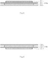
- a radical unit 110a may be formed by stacking two electrodes 111 and 113 and two separators 112 and 114.
- a cathode and an anode may naturally face each other through the separator.
- an electrode 111 is positioned at one end of the radical unit (see the electrode 111 in FIGS. 1 and 2 ) and a separator 114 is positioned at the other end of the radical unit (see the separator 114 in FIGS. 1 and 2 ).
- the electrode assembly according to the present disclosure is basically characterized in that the cell stack part or electrode assembly is formed by only stacking the radical units. That is, the present disclosure has a basic characteristic in that the cell stack part is formed by repeatedly stacking one kind of radical unit or by stacking at least two kinds of radical units in a predetermined order. To realize the above-described characteristic, the radical unit may have the following structure.
- the radical unit may be formed by stacking a first electrode, a first separator, a second electrode, and a second separator in sequence.
- a first electrode 111, a first separator 112, a second electrode 113, and a second separator 114 may be stacked in sequence from an upper side to a lower side, as illustrated in FIG. 1 , or from the lower side to the upper side, as illustrated in FIG. 2 , to form radical units 110a and 110b.
- the radical unit having the above-described structure may be referred to as a first radical unit.
- the first electrode 111 and the second electrode 113 may be opposite types of electrodes .
- the second electrode 113 may be an anode.
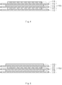
- a cell stack part 100a may be formed by only repeatedly stacking the one kind of radical units 110a, as illustrated in FIG. 3 .
- the radical unit may have an eight-layered structure or twelve-layered structure in addition to a four-layered structure. That is, the radical unit may have a repeating structure in which the four-layered structure is repeatedly disposed.
- the radical unit may be formed by stacking the first electrode 111, the first separator 112, the second electrode 113, the second separator 114, the first electrode 111, the first separator 112, the second electrode 113, and the second separator 114 in sequence.
- the radical unit may be formed by stacking the first electrode 111, the first separator 112, the second electrode 113, the second separator 114, the first electrode 111, and the first separator 112 in sequence, or by stacking the second electrode 113, the second separator 114, the first electrode 111, the first separator 112, the second electrode 113, and the second separator 114 in sequence.
- the radical unit having the former structure may be referred to as a second radical unit and the radical unit having the latter structure may be referred to as a third radical unit.
- the second radical unit 100c may be formed by stacking the first electrode 111, the first separator 112, the second electrode 113, the second separator 114, the first electrode 111, and the first separator 112 in sequence from the upper side to the lower side, as illustrated in FIG. 4 .
- the third radical structure 110d may be formed by stacking the second electrode 113, the second separator 114, the first electrode 111, the first separator 112, the second electrode 113, and the second separator 114 in sequence from the upper side to the lower side, as illustrated in FIG. 5 . As noted above, the stacking may be conducted in sequence from the lower side to the upper side.
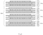
- the cell stack part 100b may be formed by stacking only the second and third radical units, as illustrated in FIG. 6 .
- the cell stack part may be formed by stacking the radical units in a predetermined order, for example, the first radical unit, the second radical unit, the third radical unit, the first radical unit again, the second radical unit, and the third radical unit.
- the one kind of radical unit in the present disclosure has a four-layered structure in which a first electrode, a first separator, a second electrode and a second separator are sequentially stacked, or has a repeating structure in which the four-layered structure is repeatedly stacked.
- at least two kinds of radical units in the present disclosure are stacked only by ones in a predetermined order to form the four-layered structure or the repeating structure in which the four-layered structure is repeatedly disposed.
- the first radical unit forms a four-layered structure by itself
- the second radical unit and the third radical unit form a twelve-layered structure by stacking one of each, that is, two radical units in total.
- the cell stack part or electrode assembly may be formed only by stacking, that is, by repeatedly stacking one kind of radical unit or by stacking at least two kinds of radical units in a predetermined order.
- the cell stack part of the present disclosure may be formed by stacking the radical units one by one. That is, the cell stack part may be manufactured by forming the radical units and then stacking the radical units repeatedly or in a predetermined order. As described above, the cell stack part of the present disclosure may be formed by only stacking the radical units. Therefore, the radical units of the present disclosure may be very accurately aligned. When the radical unit is accurately aligned, the electrode and the separator may also be accurately aligned in the cell stack part. In addition, the cell stack part or electrode assembly may be improved in productivity. This is done because the manufacturing process is very simple.
- a manufacturing process of the first radical unit will be exemplarily described with reference to FIG. 7 .
- a first electrode material 121, a first separator material 122, a second electrode material 123 and a second separator material 124 are prepared.
- the first separator material 122 and the second separator material 124 may be the same.
- the first electrode material 121 is cut into a certain size through a cutter C1
- the second electrode material 123 is cut into a certain size through a cutter C2.
- the first electrode material 121 is stacked on the first separator material 122
- the second electrode material 123 is stacked on the second separator material 124.
- the electrode materials and the separator materials are attached to each other through laminators L1 and L2.
- a radical unit in which the electrodes and the separators are integrally combined may be formed.
- the combining method may be diverse.
- the laminators L1 and L2 may apply pressure to the materials or apply pressure and heat to the materials to attach the materials to each other.
- the stacking of the radical units may be more easily performed while manufacturing the cell stack part.
- the alignment of the radical units may be also easily accomplished because of the attachment.
- the first separator material 122 and the second separator material 124 are cut into a certain size through a cutter C3 to manufacture the radical unit 110a.During this process, the edges of the separators are not joined with each other.
- the electrode is attached to the adjacent separator in the radical unit.
- the electrode may be stably fixed to the separator.
- the electrode has a size less than that of the separator.
- an adhesive may be applied to the separator.
- the adhesive it is necessary to apply the adhesive over an adhesion surface of the separator in a mesh or dot shape. This is because if the adhesive is closely applied to the entire adhesion surface, reactive ions such as lithium ions may not pass through the separator. Thus, when the adhesive is used, it is difficult to allow the overall surface of the electrode to closely attach to the adjacent separator.
- the separator may include a porous separator base material such as a polyolefin-based separator base material and a porous coating layer that is generally applied to one side or both sides of the separator base material.
- the coating layer may be formed of a mixture of inorganic particles and a binder polymer that binds and fixes the inorganic particles to each other.
- the inorganic particles may improve thermal stability of the separator. That is, the inorganic particles may prevent the separator from being contracted at a high temperature.
- the binder polymer may fix the inorganic particles to improve mechanical stability of the separator.
- the binder polymer may attach the electrode to the separator. Since the binder polymer is generally distributed in the coating layer, the electrode may closely adhere to the entire adhesion surface of the separator, unlike the foregoing adhesive. Thus, when the separator is used as described above, the electrode may be more stably fixed to the separator. To enhance the adhesion, the above-described laminators may be used.
- the inorganic particles may have a densely packed structure to form interstitial volumes between the inorganic particles over the overall coating layer.
- a pore structure may be formed in the coating layer by the interstitial volumes that are defined by the inorganic particles. Due to the pore structure, even though the coating layer is formed on the separator, the lithium ions may smoothly pass through the separator.
- the interstitial volume defined by the inorganic particles may be blocked by the binder polymer according to a position thereof.
- the densely packed structure may be explained as a structure in which gravels are contained in a glass bottle.
- the inorganic particles form the densely packed structure
- the interstitial volumes between the inorganic particles are not locally formed in the coating layer, but generally formed in the coating layer.
- the pore formed by the interstitial volume also increases in size. Due the above-described densely packed structure, the lithium ions may smoothly pass through the separator over the entire surface of the separator.
- the radical units may also adhere to each other in the cell stack part. For example, if the adhesive or the above-described coating layer is applied to a bottom surface of the second separator 114 in FIG. 1 , the other radical unit may adhere to the bottom surface of the second separator 114.
- the adhesive strength between the electrode and the separator in the radical unit is greater than that between the radical units in the cell stack part. It is understood, that the adhesive strength between the radical units may not be provided. In this case, when the electrode assembly or the cell stack part is disassembled, the electrode assembly may be separated into the radical units due to a difference in the adhesive strength.
- the adhesive strength may be expressed as delamination strength.
- the adhesive strength between the electrode and the separator may be expressed as a force required for separating the electrode from the separator.
- the radical unit may not be bonded to the adjacent radical unit in the cell stack part, or may be bonded to the adjacent radical unit in the cell stack part by means of a bonding strength differing from a bonding strength between the electrode and the separator.
- the separator when the separator includes the above-described coating layer, it is not preferable to perform ultrasonic welding on the separator.
- the separator has a size greater than that of the electrode.
- the separator may adhere to the horn due to the coating layer having the adhesive strength. As a result, the welding apparatus may be broken down.
- radical units having the same size have been explained.
- the radical units of the present invention have different sizes.
- cell stack parts having various shapes may be manufactured.
- the size of the radical unit is explained with reference to the size of the separator, because, typically, the separator is larger than the electrode.
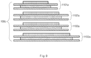
- a plurality of radical units is prepared and may be classified into at least two groups having different sizes (see reference numerals 1101a, 1102a and 1103a in FIG. 9 ).
- a cell stack part 100c having a structure of a plurality of steps is formed.
- FIGS. 8 and 9 illustrate an embodiment in which the cell stack part includes three steps obtained by stacking the radical units 1101a, 1102a and 1103a classified into three groups, in which the radical units having the same size are stacked together, is illustrated.
- the cell stack part 100c in FIGS. 8 and 9 have a structure including three steps.
- the radical units included in one group may form two or more steps .
- the radical unit has a structure of the first radical unit, that is, the above-described four-layered structure or the repeating structure in which the four-layered structure is repeatedly stacked.
- the radical units are considered to be included in one kind of radical unit even though the radical units have the same stacked structures of the but have different sizes.
- the same number of cathodes and the anodes are stacked in one step. Also, it is preferable that opposite electrodes face each other through a separator between one step and another step.
- the second and third radical units two kinds of the radical units are necessary for forming one step.
- the radical unit has the four-layered structure or the repeating structure in which the four-layered structure is repeatedly stacked, number of kinds of radical units may decrease even though a plurality of the steps is formed.
- the one step may have at least a twelve-layered structure.
- the first radical unit only one kind of radical unit is necessary to be stacked to form one step.
- one step may have at least a four-layered structure.
- the radical units may have not only different sizes but also different geometric shapes.
- the radical units may have different sizes and different edge shapes, and may or may not have a through hole as illustrated in FIG. 10 .
- a plurality of radical units classified into three groups may form three steps by stacking the radical units having the same geometric shapes.
- the radical units may be classified into at least two groups (each of the groups has different geometric shape).
- the radical unit may preferably have the four-layered structure or the repeating structure in which the four-layered structures are repeatedly stacked, that is, the structure of the first radical unit. (Herein, the radical units are considered to be included in one kind of radical unit even though the radical units have the same stacked structure but have different geometric shapes.)
- the electrode assembly according to the present disclosure may further include an auxiliary unit stacked on at least one among the uppermost part or the lowermost part of the cell stack part.
- the auxiliary unit may include a first auxiliary unit and a second auxiliary unit.
- first auxiliary unit will be described below.
- an electrode is positioned at one end of the radical unit, and a separator is positioned at the other end of the radical unit.
- the electrode may be positioned at the uppermost portion or at the lowermost portion of the cell stack part (see reference numeral 116 in FIG. 11 , and this electrode may be referred to as a terminal electrode 116) .
- the first auxiliary unit is additionally stacked on the terminal electrode.
- the first auxiliary unit 130a may be formed by stacking outward from the terminal electrode 116, a separator 114, an anode 113, a separator 112, and a cathode 111 in sequence, as illustrated in FIG. 11 .
- the terminal electrode 116 is an anode
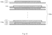
- the first auxiliary unit 130b may be formed by stacking outward from the terminal electrode 116, the separator 114, and the cathode 113 in sequence, as illustrated in FIG. 12 .
- a separator may be further stacked on the outer side of the first auxiliary unit as occasion demands.
- a cathode may be positioned at the outermost portion of a terminal electrode through the first auxiliary units 130a and 130b stacked in the cell stack parts 100d and 100e, as illustrated in FIGS. 11 and 12 .
- an active material layer is preferably coated on only one side facing the radical unit (one side facing downward in FIG. 11 ) among both sides of the current collector.
- the active material layer is not positioned at the outermost portion of the cell stack part. Thus, waste of the active material layer may be prevented.
- the cathode emits, for example, lithium ions, when the cathode is positioned at the outermost portion, the capacity of a battery may be improved.
- the second auxiliary unit performs the same function as the first auxiliary unit, which will be described below in more detail.
- an electrode is positioned at one end of the radical unit, and a separator is positioned at the other end of the radical unit.
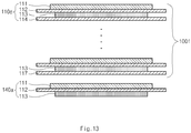
- the separator may be positioned at the uppermost portion or at the lowermost portion of the cell stack part (see reference numeral 117 in FIG. 13 , and this separator may be referred to as a terminal separator 117) .
- the second auxiliary unit is additionally stacked on the terminal separator.
- the second auxiliary unit 140a when the electrode 113 contacting the terminal separator 117 is a cathode in the radical unit, the second auxiliary unit 140a may be formed by stacking from the terminal separator 117, an anode 111, a separator 112, and a cathode 113 in sequence, as illustrated in FIG. 13 .
- the second auxiliary unit 140b when the electrode 113 contacting the terminal separator 117 is an anode in the radical unit, the second auxiliary unit 140b may be formed as the cathode 111, as illustrated in FIG. 14 .
- a cathode may be positioned at the outermost portion of a terminal separator through the second auxiliary units 140a and 140b stacked in the cell stack parts 100f and 100g, as illustrated in FIGS. 13 and 14 .
- an active material layer is preferably coated on only one side facing the radical unit (one side facing upward in FIG. 13 ) among both sides of the current collector, as similar to the cathode of the first auxiliary unit.
- the first auxiliary unit and the second auxiliary unit may have different structures from those described above.
- the first auxiliary unit will be described below.
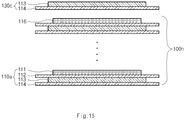
- the terminal electrode 116 is a cathode as illustrated in FIG. 15
- the first auxiliary unit 130c may be formed by stacking from the terminal electrode 116, a separator 114, and an anode 113 in sequence.
- the terminal electrode 116 is an anode as illustrated in FIG. 16
- the first auxiliary unit 130d may be formed by stacking from the terminal electrode 116, a separator 114, a cathode 113, a separator 112, and an anode 111 in sequence.
- an anode may be positioned at the outermost portion of the terminal electrode through the first auxiliary units 130c and 130d stacked in the cell stack parts 100h and 100i as illustrated in FIGS. 15 and 16 .
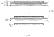
- the second auxiliary unit 140c when the electrode 113 contacting the terminal separator 117 is a cathode in the radical unit, the second auxiliary unit 140c may be formed as an anode 111. As illustrated in FIG. 18 , when the electrode 113 contacting the terminal separator 117 is an anode in the radical unit, the second auxiliary unit 140d may be formed by stacking from the terminal separator 117, the cathode 111, the separator 112, and the anode 113 in sequence.
- an anode may be positioned at the outermost portion of the terminal separator through the second auxiliary units 140c and 140d stacked in the cell stack parts 100j and 100k, as illustrated in FIGS. 17 and 18 .
- an anode may make a reaction with an aluminum layer of a battery case (for example, a pouch-type case) due to potential difference.
- the anode is preferably insulated from the battery case by means of a separator.
- the first and second auxiliary units in FIGS. 15 to 18 may further include a separator at the outer portion of the anode.
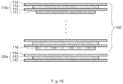
- the first auxiliary unit 130e in FIG. 19 may further include a separator 112 at the outermost portion thereof when compared with the first auxiliary unit 130c in FIG. 15 .
- the auxiliary unit includes the separator, the alignment of the auxiliary units in the radical unit may be easily performed.
- a cell stack part 100m and an electrode assembly in which first and second auxiliary units 130f and 140e are stacked on the cell stack part 100m may be formed as illustrated in FIG. 20 .
- a radical unit 110b may be formed by stacking from the lower portion to the upper portion, a first electrode 111, a first separator 112, a second electrode 113, and a second separator 114 in sequence.
- the first electrode 111 may be a cathode
- the second electrode 113 may be an anode.
- a first auxiliary unit 130f may be formed by stacking from the terminal electrode 116, the separator 114, the anode 113, the separator 112 and the cathode 111 in sequence. In this case, in the cathode 111 of the first auxiliary unit 130f, only one side of a current collector facing the radical unit 110b among both sides of the current collector may be coated with an active material layer.
- a second auxiliary unit 140e may be formed by stacking from the terminal separator 117, the cathode 111 (the first cathode), the separator 112, the anode 113, the separator 114, and the cathode 118 (the second cathode) in sequence.
- the cathode 118 the (second cathode) of the second auxiliary unit 140e positioned at the outermost portion, only one side of a current collector facing the radical unit 110b among both sides of the current collector may be coated with an active material layer.
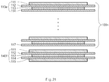
- a cell stack part 100n and an electrode assembly in which a second auxiliary unit 140f is stacked on the lowermost part of the cell stack part 100n may be formed as illustrated in FIG. 21 .
- a radical unit 110e may be formed by stacking from the upper portion to the lower portion, a first electrode 111, a first separator 112, a second electrode 113, and a second separator 114 in sequence.
- the first electrode 111 may be an anode
- the second electrode 113 may be a cathode.
- a second auxiliary unit 140f may be formed by stacking from the terminal separator 117, the anode 111, the separator 112, the cathode 113, the separator 114, and the anode 119 in sequence.
- a polymer secondary battery cell including the above-described electrode assembly may be manufactured.
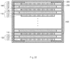
- the polymer secondary battery cell according to the present disclosure may include an electrode assembly including a cell stack part 100 and an auxiliary unit, a fixing part 200 for fixing the cell stack part 100 and the auxiliary unit, and a pouch case 300 for accommodating the fixing part 200 and the electrode assembly, as illustrated in FIGS. 22 .
- the auxiliary unit may include first and second auxiliary units 130 and 140.
- As the fixing part 200 a polymer tape exhibiting adhesive property when soaked in water may be used.
- the electrode assembly including the cell stack part 100 may include first and second auxiliary units 130 and 140 stacked on the uppermost part or the lowermost part of the cell stack part 100, respectively and the fixing part 200 may fix the cell stack part 100b and the first and second auxiliary units 130 and 140.
- the polymer secondary battery cell according to the present disclosure includes an electrode assembly having a novel structure that is distinguished from a stack-type or a stack/folding type structure.
- the stacking method of the electrode assembly may be simplified, and commercial value of a product may be improved.
Claims (20)
- Ensemble d'électrodes, comprenant :une partie d'empilement de cellules (100) ayant (a) une structure dans laquelle une sorte d'unité radicale est disposée de façon répétée, ladite sorte d'unité radicale (110) ayant un même nombre d'électrodes et de séparateurs qui sont disposés en alternance et combinés d'un seul tenant, ou (b) une structure dans laquelle au moins deux sortes d'unités radicales sont disposées dans un ordre prédéterminé, les au moins deux sortes d'unités radicales ayant chacune un même nombre d'électrodes et de séparateurs qui sont disposés en alternance et combinés d'un seul tenant ;une unité auxiliaire (130, 140) disposée sur au moins l'une parmi une partie la plus haute ou une partie la plus basse de la partie d'empilement de cellules (100) ; etune partie de fixation (200) pour fixer la partie d'empilement de cellules (100) et l'unité auxiliaire (130a, 140),dans lequel ladite sorte d'unité radicale de (a) a une structure à quatre couches dans laquelle une première électrode (111), un premier séparateur (112), une seconde électrode (113) et un second séparateur (114) sont empilés séquentiellement ensemble ou une structure répétitive dans laquelle la structure à quatre couches est empilée de façon répétée ; etdans lequel chacune des au moins deux sortes d'unités radicales de (b) est empilée une à une dans l'ordre prédéterminé pour former la structure à quatre couches ou la structure répétitive dans laquelle la structure à quatre couches est empilée de façon répétée, etchacune des électrodes est attachée à un séparateur adjacent dans chaque unité radicale,une force d'adhésion entre chacune des électrodes et le séparateur adjacent dans l'unité radicale est supérieure à une force d'adhésion entre les unités radicales dans la partie d'empilement de cellules (100),caractérisé en ce queles séparateurs comportent une couche de revêtement ayant une force d'adhésion pour attacher les électrodes aux séparateurs,les unités radicales de ladite sorte d'unité radicale de (a) ou des au moins deux sortes d'unités radicales de (b) ont des tailles différentes, etla partie d'empilement de cellules (100) a une structure dans laquelle une pluralité de décrochements est formée en empilant les unités radicales ayant des tailles différentes.
- Ensemble d'électrodes selon la revendication 1, dans lequel un bord du séparateur n'est pas joint à un bord d'un séparateur adjacent.
- Ensemble d'électrodes selon la revendication 1,
dans lequel les au moins deux sortes d'unités radicales de (b) comprennent :une deuxième unité radicale (110c) ayant la première électrode (111), le premier séparateur (112), la seconde électrode (113), le second séparateur (114), la première électrode (111), et le premier séparateur (112), qui sont disposés séquentiellement et combinés d'un seul tenant ; etune troisième unité radicale (110d) ayant la seconde électrode (113), le second séparateur (114), la première électrode (111), le premier séparateur (112), la seconde électrode (113), et le second séparateur (114), qui sont disposés séquentiellement et combinés d'un seul tenant, etdans lequel la partie d'empilement de cellules (100) a une structure dans laquelle la deuxième unité radicale et la troisième unité radicale sont disposées en alternance. - Ensemble d'électrodes selon la revendication 1,
dans lequel ladite sorte d'unité radicale de (a) est prévue en pluralité et la pluralité de ladite sorte d'unités radicales est classée en au moins deux groupes ayant des formes géométriques différentes, et
dans lequel la partie d'empilement de cellules (100) a une structure dans laquelle une pluralité de décrochements est formée en empilant ladite sorte d'unités radicales de (a) selon leur forme géométrique. - Ensemble d'électrodes selon la revendication 1, dans lequel une surface entière de chacune des électrodes faisant face au séparateur adjacent, est attachée au séparateur adjacent.
- Ensemble d'électrodes selon la revendication 1,
dans lequel le séparateur comprend un matériau de base de séparateur poreux et une couche de revêtement poreuse qui est appliquée à une surface entière d'un côté ou des deux côtés du matériau de base de séparateur,
dans lequel la couche de revêtement poreuse comprend un mélange de particules inorganiques et d'un polymère liant, dans lequel le polymère liant lie et fixe les particules inorganiques les unes aux autres, et
dans lequel chacune des électrodes est attachée au séparateur adjacent par la couche de revêtement. - Ensemble d'électrodes selon la revendication 6,
dans lequel les particules inorganiques de la couche de revêtement poreuse ont une structure à garnissage dense pour former des volumes interstitiels entre les particules inorganiques par-dessus la couche de revêtement globale, et
dans lequel une structure de pore est formée dans la couche de revêtement par les volumes interstitiels qui sont définis par les particules inorganiques. - Ensemble d'électrodes selon la revendication 1,
dans lequel l'unité auxiliaire comprend une première unité auxiliaire (130a ; 130b)) empilée sur une électrode terminale qui est une électrode la plus haute ou la plus basse de la partie d'empilement de cellules (100),
dans lequel, lorsque l'électrode terminale est une cathode, la première unité auxiliaire (130a) est formée en empilant à partir de l'électrode terminale (116), un séparateur (114), une anode (113), un séparateur (112), et une cathode (111) en séquence, et
dans lequel, lorsque l'électrode terminale est une anode, la première unité auxiliaire (130b) est formée en empilant à partir de l'électrode terminale (116), un séparateur (114) et une cathode (113) en séquence. - Ensemble d'électrodes selon la revendication 8, dans lequel la cathode de la première unité auxiliaire comprend :un collecteur de courant ; etun matériau actif revêtu sur uniquement un côté faisant face à l'unité radicale parmi les deux côtés du collecteur de courant.
- Ensemble d'électrodes selon la revendication 8,
dans lequel l'unité auxiliaire comprend une seconde unité auxiliaire (140a, 140b) sur un séparateur terminal qui est un séparateur le plus haut ou le plus bas de la partie d'empilement de cellules (100),
dans lequel, lorsque l'électrode entrant en contact avec le séparateur terminal est une cathode dans l'unité radicale, la seconde unité auxiliaire (140a) est formée en empilant à partir du séparateur terminal (117), une anode (111), un séparateur (112) et une cathode (113) en séquence, et
dans lequel, lorsque l'électrode entrant en contact avec le séparateur terminal est une anode dans l'unité radicale, la seconde unité auxiliaire (140b) est formée en tant que cathode (111). - Ensemble d'électrodes selon la revendication 10, dans lequel la cathode de la seconde unité auxiliaire comprend :un collecteur de courant ; etun matériau actif revêtu sur uniquement un côté faisant face à l'unité radicale parmi les deux côtés du collecteur de courant.
- Ensemble d'électrodes selon la revendication 1,
dans lequel l'unité auxiliaire comprend une première unité auxiliaire (130c, 130d) empilée sur une électrode terminale disposée sur une électrode la plus haute ou la plus basse de la partie d'empilement de cellules (100),
dans lequel, lorsque l'électrode terminale est une cathode, la première unité auxiliaire (130c) est formée en empilant à partir de l'électrode terminale (116), un séparateur (114) et une anode (113) en séquence, et
dans lequel, lorsque l'électrode terminale est une anode, la première unité auxiliaire (130d) est formée en empilant à partir de l'électrode terminale (116), un séparateur (114), une cathode (113), un séparateur (112) et une anode (111) en séquence. - Ensemble d'électrodes selon la revendication 12, dans lequel la première unité auxiliaire comprend en outre un séparateur au niveau d'un côté externe de l'anode.
- Ensemble d'électrodes selon la revendication 8,
dans lequel l'unité auxiliaire comprend une seconde unité auxiliaire (140c, 140d) sur un séparateur terminal qui est un séparateur le plus haut ou le plus bas de la partie d'empilement de cellules (100),
dans lequel, lorsque l'électrode entrant en contact avec le séparateur terminal est une cathode dans l'unité radicale, la seconde unité auxiliaire (140c) est formée en tant qu'anode (111), et
dans lequel, lorsque l'électrode entrant en contact avec le séparateur terminal est une anode dans l'unité radicale, la seconde unité auxiliaire (140d) est formée en empilant à partir du séparateur terminal (117), une cathode (111), un séparateur (112), et une anode (113) en séquence. - Ensemble d'électrodes selon la revendication 14, dans lequel la seconde unité auxiliaire comprend en outre un séparateur au niveau d'un côté externe de l'anode.
- Ensemble d'électrodes selon la revendication 8,
dans lequel l'unité auxiliaire comprend une seconde unité auxiliaire (140e) empilée sur un séparateur terminal qui est un séparateur le plus haut ou le plus bas de la partie d'empilement de cellules, et
dans lequel, lorsque l'électrode entrant en contact avec le séparateur terminal dans l'unité radicale est une anode, la seconde unité auxiliaire est formée en empilant à partir du séparateur terminal (117), une première cathode (111), un séparateur (112), une anode (113), un séparateur (114), et une seconde cathode (118) en séquence. - Ensemble d'électrodes selon la revendication 16, dans lequel la seconde cathode de la seconde unité auxiliaire comprend :un collecteur de courant ; etun matériau actif revêtu sur uniquement un côté faisant face à l'unité radicale parmi les deux côtés du collecteur de courant.
- Ensemble d'électrodes selon la revendication 8,
dans lequel l'unité auxiliaire comprend une seconde unité auxiliaire (140f) empilée sur un séparateur terminal qui est un séparateur le plus haut ou le plus bas de la partie d'empilement de cellules, et
dans lequel, lorsque l'électrode entrant en contact avec le séparateur terminal est une cathode dans l'unité radicale, la seconde unité auxiliaire est formée en empilant à partir du séparateur terminal (117), une première anode (111), un séparateur (112), une cathode (113), un séparateur (114), et une seconde anode (119) en séquence. - Cellule de batterie secondaire à polymère, comprenant :l'ensemble d'électrodes selon la revendication 1 ; etun étui logeant l'ensemble d'électrodes.
- Procédé de fabrication d'un ensemble d'électrodes selon la revendication 1, le procédé comprenant :une première étape de formation d'une sorte d'une unité radicale ayant une structure empilée en alternance d'un même nombre d'électrodes et de séparateurs, ou d'au moins deux sortes d'unités radicales ayant une structure empilée en alternance d'un même nombre d'électrodes et de séparateurs ;une deuxième étape de formation d'une partie d'empilement de cellules (100) en empilant de façon répétée ladite sorte des unités radicales, ou en empilant les au moins deux sortes des unités radicales dans un ordre prédéterminé ;une troisième étape d'empilement d'une unité auxiliaire (130, 140) sur au moins l'une parmi une partie la plus haute ou une partie la plus basse de la partie d'empilement de cellules (100) ; etune quatrième étape de fixation de la partie d'empilement de cellules (100) et de l'unité auxiliaire (130, 140) par une partie de fixation (200) qui est une bande en polymère présentant une propriété d'adhésion lorsqu'elle est trempée dans l'eau,dans lequel ladite sorte d'unité radicale a une structure à quatre couches dans laquelle une première électrode, un premier séparateur, une seconde électrode et un second séparateur sont empilés séquentiellement ensemble ou une structure répétitive dans laquelle la structure à quatre couches est empilée de façon répétée ; etdans lequel chacune des au moins deux sortes d'unités radicales est empilée une à une dans l'ordre prédéterminé pour former la structure à quatre couches ou la structure répétitive dans laquelle la structure à quatre couches est empilée de façon répétée.
Applications Claiming Priority (2)
| Application Number | Priority Date | Filing Date | Title |
|---|---|---|---|
| KR20130016510 | 2013-02-15 | ||
| PCT/KR2014/001264 WO2014126430A1 (fr) | 2013-02-15 | 2014-02-17 | Ensemble électrode et cellule de batterie secondaire polymère comprenant celui-ci |
Publications (3)
| Publication Number | Publication Date |
|---|---|
| EP2814103A1 EP2814103A1 (fr) | 2014-12-17 |
| EP2814103A4 EP2814103A4 (fr) | 2015-06-03 |
| EP2814103B1 true EP2814103B1 (fr) | 2017-12-06 |
Family
ID=51747583
Family Applications (1)
| Application Number | Title | Priority Date | Filing Date |
|---|---|---|---|
| EP14752035.7A Active EP2814103B1 (fr) | 2013-02-15 | 2014-02-17 | Ensemble électrode et cellule de batterie secondaire polymère comprenant celui-ci |
Country Status (7)
| Country | Link |
|---|---|
| US (3) | US10418609B2 (fr) |
| EP (1) | EP2814103B1 (fr) |
| JP (2) | JP2015527709A (fr) |
| KR (1) | KR101567675B1 (fr) |
| CN (1) | CN104221201B (fr) |
| TW (1) | TWI520403B (fr) |
| WO (1) | WO2014126430A1 (fr) |
Families Citing this family (12)
| Publication number | Priority date | Publication date | Assignee | Title |
|---|---|---|---|---|
| CN104662725B (zh) | 2013-05-23 | 2020-07-03 | 株式会社Lg 化学 | 电极组件及用于该电极组件的基本单体 |
| KR101561735B1 (ko) | 2013-09-25 | 2015-10-19 | 주식회사 엘지화학 | 전극조립체 제조방법 |
| KR101619604B1 (ko) * | 2013-09-26 | 2016-05-10 | 주식회사 엘지화학 | 전극조립체 및 이차전지의 제조방법 |
| KR101609424B1 (ko) | 2013-09-26 | 2016-04-05 | 주식회사 엘지화학 | 전극조립체의 제조방법 |
| JP6946295B2 (ja) * | 2016-07-28 | 2021-10-06 | 三洋電機株式会社 | 二次電池の製造方法 |
| JP6787241B2 (ja) * | 2017-04-28 | 2020-11-18 | トヨタ自動車株式会社 | 電極積層体及び電池の製造方法 |
| KR102217447B1 (ko) | 2017-07-06 | 2021-02-22 | 주식회사 엘지화학 | 이차전지 |
| US11264641B2 (en) | 2018-01-10 | 2022-03-01 | Samsung Electronics Co., Ltd. | All-solid secondary battery, multilayered all-solid secondary battery, and method of manufacturing all-solid secondary battery |
| KR102328527B1 (ko) * | 2018-12-24 | 2021-11-18 | 주식회사 엘지에너지솔루션 | 벤딩 현상이 개선된 스택형 전극 조립체 및 이의 제조방법 |
| CN110391449A (zh) * | 2019-07-16 | 2019-10-29 | 蜂巢能源科技有限公司 | 模切叠片系统及方法 |
| KR20210065655A (ko) * | 2019-11-27 | 2021-06-04 | 주식회사 엘지화학 | 전극조립체 및 그 제조방법 |
| EP4343904A1 (fr) * | 2021-08-18 | 2024-03-27 | LG Energy Solution, Ltd. | Ensemble électrode et batterie secondaire le comprenant |
Family Cites Families (42)
| Publication number | Priority date | Publication date | Assignee | Title |
|---|---|---|---|---|
| US6224995B1 (en) * | 1997-03-06 | 2001-05-01 | Mitsubishi Chemical Corporation | Three dimensional free form battery apparatus |
| JP3829398B2 (ja) | 1997-03-28 | 2006-10-04 | 株式会社ジーエス・ユアサコーポレーション | 電池の製造方法 |
| JP4271756B2 (ja) * | 1998-12-02 | 2009-06-03 | 日東電工株式会社 | 電池用接着剤又は粘着剤もしくは粘着テープ・シート |
| JP2001028275A (ja) * | 1999-06-25 | 2001-01-30 | Mitsubishi Chemicals Corp | 立体自由形状バッテリー装置 |
| JP3611765B2 (ja) * | 1999-12-09 | 2005-01-19 | シャープ株式会社 | 二次電池及びそれを用いた電子機器 |
| KR100515571B1 (ko) | 2000-02-08 | 2005-09-20 | 주식회사 엘지화학 | 중첩 전기 화학 셀 |
| KR100515572B1 (ko) * | 2000-02-08 | 2005-09-20 | 주식회사 엘지화학 | 중첩 전기화학 셀 및 그의 제조 방법 |
| JP4644899B2 (ja) | 2000-02-23 | 2011-03-09 | ソニー株式会社 | 電極及び電池、並びにそれらの製造方法 |
| JP2002151159A (ja) | 2000-09-01 | 2002-05-24 | Nisshinbo Ind Inc | リチウム系電池 |
| US7332242B2 (en) | 2000-09-01 | 2008-02-19 | Itochu Corporation | Lithium-based battery having extensible, ion-impermeable polymer covering on the battery container |
| KR100406690B1 (ko) * | 2001-03-05 | 2003-11-21 | 주식회사 엘지화학 | 다성분계 복합 필름을 이용한 전기화학소자 |
| JP2002342004A (ja) * | 2001-05-11 | 2002-11-29 | Sony Corp | 文字入力方法及び文字入力装置 |
| KR100467690B1 (ko) * | 2001-11-06 | 2005-01-24 | 삼성에스디아이 주식회사 | 이차전지의 전극 젤리 롤용 마감 테이프를 구비한 이차전지의 전극 조합체 |
| US6844109B2 (en) * | 2001-12-18 | 2005-01-18 | Ngk Spark Plug Co., Ltd. | Li-ion and/or Li-ion polymer battery with edge protectors |
| KR100440934B1 (ko) * | 2002-02-06 | 2004-07-21 | 삼성에스디아이 주식회사 | 이차전지 |
| JP4281382B2 (ja) * | 2002-04-19 | 2009-06-17 | ソニー株式会社 | 生成水処理システム及び発電装置 |
| US20060011571A1 (en) * | 2002-11-08 | 2006-01-19 | Silver Brian H | Artificial nipple with reinforcement |
| KR100513645B1 (ko) * | 2003-03-20 | 2005-09-07 | 주식회사 엘지화학 | 최외곽 전극이 분리막에 의해 포켓팅된 적층형 전지 |
| KR100895196B1 (ko) * | 2004-09-02 | 2009-04-24 | 주식회사 엘지화학 | 유/무기 복합 다공성 필름 및 이를 이용한 전기 화학 소자 |
| EP1784876B1 (fr) | 2004-09-02 | 2018-01-24 | LG Chem, Ltd. | Film poreux composite organique/mineral et dispositif electrochimique prepare au moyen de ce film |
| JP4846717B2 (ja) | 2004-09-02 | 2011-12-28 | エルジー・ケム・リミテッド | 有無機複合多孔性フィルム及びこれを用いる電気化学素子 |
| US20060115718A1 (en) * | 2004-11-30 | 2006-06-01 | Delphi Technologies, Inc. | Lithium ion polymer multi-cell and method of making |
| KR100758482B1 (ko) | 2004-12-07 | 2007-09-12 | 주식회사 엘지화학 | 표면 처리된 다공성 필름 및 이를 이용한 전기 화학 소자 |
| KR100775310B1 (ko) | 2004-12-22 | 2007-11-08 | 주식회사 엘지화학 | 유/무기 복합 다공성 분리막 및 이를 이용한 전기 화학소자 |
| TW200743245A (en) | 2006-05-01 | 2007-11-16 | Antig Tech Co Ltd | Assembly method used in the assembly of flat-plate type membrane electrode assembled layer and its structure |
| KR100874387B1 (ko) | 2006-06-13 | 2008-12-18 | 주식회사 엘지화학 | 둘 이상의 작동 전압을 제공하는 중첩식 이차전지 |
| KR100878700B1 (ko) | 2006-06-26 | 2009-01-14 | 주식회사 엘지화학 | 전지셀 제조용 전극판 및 그것의 제조방법 |
| KR100894408B1 (ko) * | 2006-07-10 | 2009-04-24 | 주식회사 엘지화학 | 향상된 안전성의 스택/폴딩형 전극조립체 및 이를 포함하는전기화학 셀 |
| TW200812138A (en) | 2006-08-18 | 2008-03-01 | Antig Technology Corp | Flat type membrane electrode layer structure |
| WO2009014388A2 (fr) * | 2007-07-25 | 2009-01-29 | Lg Chem, Ltd. | Dispositif électrochimique et son procédé de fabrication |
| US20120022534A1 (en) * | 2008-09-17 | 2012-01-26 | Skeletal Dynamics Llc | Intramedullary arthrodesis nail and method of use |
| CN102138244B (zh) | 2009-03-31 | 2014-05-28 | 三菱重工业株式会社 | 二次电池及电池系统 |
| US20110024430A1 (en) * | 2009-08-03 | 2011-02-03 | Meissen Cynthia R | Reusable waste container |
| KR101103499B1 (ko) | 2009-10-07 | 2012-01-06 | 에스케이이노베이션 주식회사 | 전지용 전극조립체 및 그 제조방법 |
| CN101771165B (zh) * | 2010-02-08 | 2012-07-25 | 中南大学 | 一种圆柱形锂离子动力电池及其制备方法 |
| JP2011210524A (ja) * | 2010-03-30 | 2011-10-20 | Sanyo Electric Co Ltd | 積層式電池 |
| KR101163053B1 (ko) * | 2010-04-06 | 2012-07-05 | 주식회사 엘지화학 | 스택 타입 셀, 개선된 바이-셀, 이들을 이용한 이차 전지용 전극 조립체 및 그 제조 방법 |
| CN102760905A (zh) * | 2011-04-28 | 2012-10-31 | 迪吉亚节能科技股份有限公司 | 高容量锂电池 |
| CN202585648U (zh) * | 2012-02-20 | 2012-12-05 | 宁德新能源科技有限公司 | 软包装叠片式电池结构 |
| KR20130113301A (ko) * | 2012-04-05 | 2013-10-15 | 주식회사 엘지화학 | 계단 구조의 전지셀 |
| EP2772978B1 (fr) * | 2012-05-23 | 2018-12-26 | LG Chem, Ltd. | Ensemble d'électrodes et dispositif électrochimique comportant un tel ensemble |
| JP6247232B2 (ja) * | 2012-05-23 | 2017-12-13 | エルジー・ケム・リミテッド | 電極組立体の製造方法及びこれにより製造される電極組立体を含む電気化学素子 |
-
2014
- 2014-02-17 EP EP14752035.7A patent/EP2814103B1/fr active Active
- 2014-02-17 WO PCT/KR2014/001264 patent/WO2014126430A1/fr active Application Filing
- 2014-02-17 KR KR1020140017698A patent/KR101567675B1/ko active IP Right Grant
- 2014-02-17 CN CN201480000983.7A patent/CN104221201B/zh active Active
- 2014-02-17 JP JP2015524207A patent/JP2015527709A/ja active Pending
- 2014-02-17 TW TW103105131A patent/TWI520403B/zh active
- 2014-08-27 US US14/469,851 patent/US10418609B2/en active Active
-
2017
- 2017-01-03 JP JP2017000010A patent/JP6467440B2/ja active Active
-
2019
- 2019-08-07 US US16/534,771 patent/US10804520B2/en active Active
-
2020
- 2020-09-01 US US17/009,272 patent/US11476546B2/en active Active
Non-Patent Citations (1)
| Title |
|---|
| None * |
Also Published As
| Publication number | Publication date |
|---|---|
| TW201501385A (zh) | 2015-01-01 |
| EP2814103A1 (fr) | 2014-12-17 |
| US20200395591A1 (en) | 2020-12-17 |
| US10804520B2 (en) | 2020-10-13 |
| CN104221201B (zh) | 2016-08-31 |
| WO2014126430A1 (fr) | 2014-08-21 |
| US10418609B2 (en) | 2019-09-17 |
| JP2017103237A (ja) | 2017-06-08 |
| US20190379026A1 (en) | 2019-12-12 |
| TWI520403B (zh) | 2016-02-01 |
| US11476546B2 (en) | 2022-10-18 |
| JP6467440B2 (ja) | 2019-02-13 |
| KR20140103084A (ko) | 2014-08-25 |
| JP2015527709A (ja) | 2015-09-17 |
| US20140363725A1 (en) | 2014-12-11 |
| CN104221201A (zh) | 2014-12-17 |
| EP2814103A4 (fr) | 2015-06-03 |
| KR101567675B1 (ko) | 2015-11-10 |
Similar Documents
| Publication | Publication Date | Title |
|---|---|---|
| EP2814103B1 (fr) | Ensemble électrode et cellule de batterie secondaire polymère comprenant celui-ci | |
| EP2882027B1 (fr) | Ensemble d'électrodes et son corps unitaire de base | |
| EP2816656B1 (fr) | Ensemble électrode et cellule de batterie secondaire polymère comprenant celui-ci | |
| EP2882028B1 (fr) | Procédé de fabrication d'un ensemble électrode | |
| US10971751B2 (en) | Electrode assembly | |
| EP2863466B1 (fr) | Ensemble électrode et procédé de production | |
| KR101807354B1 (ko) | 전극 조립체 | |
| CN111628227B (zh) | 电极组件 | |
| KR101747514B1 (ko) | 전극 조립체 |
Legal Events
| Date | Code | Title | Description |
|---|---|---|---|
| PUAI | Public reference made under article 153(3) epc to a published international application that has entered the european phase |
Free format text: ORIGINAL CODE: 0009012 |
|
| 17P | Request for examination filed |
Effective date: 20140909 |
|
| AK | Designated contracting states |
Kind code of ref document: A1 Designated state(s): AL AT BE BG CH CY CZ DE DK EE ES FI FR GB GR HR HU IE IS IT LI LT LU LV MC MK MT NL NO PL PT RO RS SE SI SK SM TR |
|
| AX | Request for extension of the european patent |
Extension state: BA ME |
|
| RA4 | Supplementary search report drawn up and despatched (corrected) |
Effective date: 20150504 |
|
| RIC1 | Information provided on ipc code assigned before grant |
Ipc: H01M 10/0585 20100101AFI20150424BHEP Ipc: H01M 10/0565 20100101ALN20150424BHEP Ipc: H01M 10/04 20060101ALN20150424BHEP Ipc: H01M 2/10 20060101ALN20150424BHEP |
|
| 17Q | First examination report despatched |
Effective date: 20160119 |
|
| DAX | Request for extension of the european patent (deleted) | ||
| RIC1 | Information provided on ipc code assigned before grant |
Ipc: H01M 2/10 20060101ALN20170406BHEP Ipc: H01M 10/0565 20100101ALN20170406BHEP Ipc: H01M 10/0585 20100101AFI20170406BHEP Ipc: H01M 10/04 20060101ALN20170406BHEP |
|
| GRAP | Despatch of communication of intention to grant a patent |
Free format text: ORIGINAL CODE: EPIDOSNIGR1 |
|
| RIC1 | Information provided on ipc code assigned before grant |
Ipc: H01M 10/0565 20100101ALN20170810BHEP Ipc: H01M 10/04 20060101ALN20170810BHEP Ipc: H01M 10/0585 20100101AFI20170810BHEP Ipc: H01M 2/10 20060101ALN20170810BHEP |
|
| INTG | Intention to grant announced |
Effective date: 20170914 |
|
| GRAJ | Information related to disapproval of communication of intention to grant by the applicant or resumption of examination proceedings by the epo deleted |
Free format text: ORIGINAL CODE: EPIDOSDIGR1 |
|
| REG | Reference to a national code |
Ref country code: DE Ref legal event code: R079 Ref document number: 602014018211 Country of ref document: DE Free format text: PREVIOUS MAIN CLASS: H01M0010040000 Ipc: H01M0010058500 |
|
| GRAR | Information related to intention to grant a patent recorded |
Free format text: ORIGINAL CODE: EPIDOSNIGR71 |
|
| GRAS | Grant fee paid |
Free format text: ORIGINAL CODE: EPIDOSNIGR3 |
|
| GRAA | (expected) grant |
Free format text: ORIGINAL CODE: 0009210 |
|
| INTC | Intention to grant announced (deleted) | ||
| RIC1 | Information provided on ipc code assigned before grant |
Ipc: H01M 2/10 20060101ALN20171017BHEP Ipc: H01M 10/04 20060101ALN20171017BHEP Ipc: H01M 10/0565 20100101ALN20171017BHEP Ipc: H01M 10/0585 20100101AFI20171017BHEP |
|
| AK | Designated contracting states |
Kind code of ref document: B1 Designated state(s): AL AT BE BG CH CY CZ DE DK EE ES FI FR GB GR HR HU IE IS IT LI LT LU LV MC MK MT NL NO PL PT RO RS SE SI SK SM TR |
|
| INTG | Intention to grant announced |
Effective date: 20171031 |
|
| REG | Reference to a national code |
Ref country code: GB Ref legal event code: FG4D |
|
| REG | Reference to a national code |
Ref country code: AT Ref legal event code: REF Ref document number: 953155 Country of ref document: AT Kind code of ref document: T Effective date: 20171215 Ref country code: CH Ref legal event code: EP |
|
| REG | Reference to a national code |
Ref country code: IE Ref legal event code: FG4D |
|
| REG | Reference to a national code |
Ref country code: DE Ref legal event code: R096 Ref document number: 602014018211 Country of ref document: DE |
|
| REG | Reference to a national code |
Ref country code: FR Ref legal event code: PLFP Year of fee payment: 5 |
|
| REG | Reference to a national code |
Ref country code: NL Ref legal event code: MP Effective date: 20171206 |
|
| REG | Reference to a national code |
Ref country code: LT Ref legal event code: MG4D |
|
| PG25 | Lapsed in a contracting state [announced via postgrant information from national office to epo] |
Ref country code: FI Free format text: LAPSE BECAUSE OF FAILURE TO SUBMIT A TRANSLATION OF THE DESCRIPTION OR TO PAY THE FEE WITHIN THE PRESCRIBED TIME-LIMIT Effective date: 20171206 Ref country code: NO Free format text: LAPSE BECAUSE OF FAILURE TO SUBMIT A TRANSLATION OF THE DESCRIPTION OR TO PAY THE FEE WITHIN THE PRESCRIBED TIME-LIMIT Effective date: 20180306 Ref country code: ES Free format text: LAPSE BECAUSE OF FAILURE TO SUBMIT A TRANSLATION OF THE DESCRIPTION OR TO PAY THE FEE WITHIN THE PRESCRIBED TIME-LIMIT Effective date: 20171206 Ref country code: LT Free format text: LAPSE BECAUSE OF FAILURE TO SUBMIT A TRANSLATION OF THE DESCRIPTION OR TO PAY THE FEE WITHIN THE PRESCRIBED TIME-LIMIT Effective date: 20171206 Ref country code: SE Free format text: LAPSE BECAUSE OF FAILURE TO SUBMIT A TRANSLATION OF THE DESCRIPTION OR TO PAY THE FEE WITHIN THE PRESCRIBED TIME-LIMIT Effective date: 20171206 |
|
| REG | Reference to a national code |
Ref country code: AT Ref legal event code: MK05 Ref document number: 953155 Country of ref document: AT Kind code of ref document: T Effective date: 20171206 |
|
| PG25 | Lapsed in a contracting state [announced via postgrant information from national office to epo] |
Ref country code: HR Free format text: LAPSE BECAUSE OF FAILURE TO SUBMIT A TRANSLATION OF THE DESCRIPTION OR TO PAY THE FEE WITHIN THE PRESCRIBED TIME-LIMIT Effective date: 20171206 Ref country code: GR Free format text: LAPSE BECAUSE OF FAILURE TO SUBMIT A TRANSLATION OF THE DESCRIPTION OR TO PAY THE FEE WITHIN THE PRESCRIBED TIME-LIMIT Effective date: 20180307 Ref country code: BG Free format text: LAPSE BECAUSE OF FAILURE TO SUBMIT A TRANSLATION OF THE DESCRIPTION OR TO PAY THE FEE WITHIN THE PRESCRIBED TIME-LIMIT Effective date: 20180306 Ref country code: LV Free format text: LAPSE BECAUSE OF FAILURE TO SUBMIT A TRANSLATION OF THE DESCRIPTION OR TO PAY THE FEE WITHIN THE PRESCRIBED TIME-LIMIT Effective date: 20171206 Ref country code: RS Free format text: LAPSE BECAUSE OF FAILURE TO SUBMIT A TRANSLATION OF THE DESCRIPTION OR TO PAY THE FEE WITHIN THE PRESCRIBED TIME-LIMIT Effective date: 20171206 |
|
| PG25 | Lapsed in a contracting state [announced via postgrant information from national office to epo] |
Ref country code: NL Free format text: LAPSE BECAUSE OF FAILURE TO SUBMIT A TRANSLATION OF THE DESCRIPTION OR TO PAY THE FEE WITHIN THE PRESCRIBED TIME-LIMIT Effective date: 20171206 |
|
| PG25 | Lapsed in a contracting state [announced via postgrant information from national office to epo] |
Ref country code: EE Free format text: LAPSE BECAUSE OF FAILURE TO SUBMIT A TRANSLATION OF THE DESCRIPTION OR TO PAY THE FEE WITHIN THE PRESCRIBED TIME-LIMIT Effective date: 20171206 Ref country code: SK Free format text: LAPSE BECAUSE OF FAILURE TO SUBMIT A TRANSLATION OF THE DESCRIPTION OR TO PAY THE FEE WITHIN THE PRESCRIBED TIME-LIMIT Effective date: 20171206 Ref country code: CZ Free format text: LAPSE BECAUSE OF FAILURE TO SUBMIT A TRANSLATION OF THE DESCRIPTION OR TO PAY THE FEE WITHIN THE PRESCRIBED TIME-LIMIT Effective date: 20171206 |
|
| PG25 | Lapsed in a contracting state [announced via postgrant information from national office to epo] |
Ref country code: RO Free format text: LAPSE BECAUSE OF FAILURE TO SUBMIT A TRANSLATION OF THE DESCRIPTION OR TO PAY THE FEE WITHIN THE PRESCRIBED TIME-LIMIT Effective date: 20171206 Ref country code: AT Free format text: LAPSE BECAUSE OF FAILURE TO SUBMIT A TRANSLATION OF THE DESCRIPTION OR TO PAY THE FEE WITHIN THE PRESCRIBED TIME-LIMIT Effective date: 20171206 Ref country code: IT Free format text: LAPSE BECAUSE OF FAILURE TO SUBMIT A TRANSLATION OF THE DESCRIPTION OR TO PAY THE FEE WITHIN THE PRESCRIBED TIME-LIMIT Effective date: 20171206 Ref country code: PL Free format text: LAPSE BECAUSE OF FAILURE TO SUBMIT A TRANSLATION OF THE DESCRIPTION OR TO PAY THE FEE WITHIN THE PRESCRIBED TIME-LIMIT Effective date: 20171206 Ref country code: SM Free format text: LAPSE BECAUSE OF FAILURE TO SUBMIT A TRANSLATION OF THE DESCRIPTION OR TO PAY THE FEE WITHIN THE PRESCRIBED TIME-LIMIT Effective date: 20171206 |
|
| REG | Reference to a national code |
Ref country code: DE Ref legal event code: R097 Ref document number: 602014018211 Country of ref document: DE |
|
| REG | Reference to a national code |
Ref country code: CH Ref legal event code: PL |
|
| PG25 | Lapsed in a contracting state [announced via postgrant information from national office to epo] |
Ref country code: MC Free format text: LAPSE BECAUSE OF FAILURE TO SUBMIT A TRANSLATION OF THE DESCRIPTION OR TO PAY THE FEE WITHIN THE PRESCRIBED TIME-LIMIT Effective date: 20171206 |
|
| PLBE | No opposition filed within time limit |
Free format text: ORIGINAL CODE: 0009261 |
|
| STAA | Information on the status of an ep patent application or granted ep patent |
Free format text: STATUS: NO OPPOSITION FILED WITHIN TIME LIMIT |
|
| 26N | No opposition filed |
Effective date: 20180907 |
|
| REG | Reference to a national code |
Ref country code: IE Ref legal event code: MM4A |
|
| REG | Reference to a national code |
Ref country code: BE Ref legal event code: MM Effective date: 20180228 |
|
| PG25 | Lapsed in a contracting state [announced via postgrant information from national office to epo] |
Ref country code: DK Free format text: LAPSE BECAUSE OF FAILURE TO SUBMIT A TRANSLATION OF THE DESCRIPTION OR TO PAY THE FEE WITHIN THE PRESCRIBED TIME-LIMIT Effective date: 20171206 Ref country code: LU Free format text: LAPSE BECAUSE OF NON-PAYMENT OF DUE FEES Effective date: 20180217 Ref country code: SI Free format text: LAPSE BECAUSE OF FAILURE TO SUBMIT A TRANSLATION OF THE DESCRIPTION OR TO PAY THE FEE WITHIN THE PRESCRIBED TIME-LIMIT Effective date: 20171206 Ref country code: CH Free format text: LAPSE BECAUSE OF NON-PAYMENT OF DUE FEES Effective date: 20180228 Ref country code: LI Free format text: LAPSE BECAUSE OF NON-PAYMENT OF DUE FEES Effective date: 20180228 |
|
| PG25 | Lapsed in a contracting state [announced via postgrant information from national office to epo] |
Ref country code: IE Free format text: LAPSE BECAUSE OF NON-PAYMENT OF DUE FEES Effective date: 20180217 |
|
| PG25 | Lapsed in a contracting state [announced via postgrant information from national office to epo] |
Ref country code: BE Free format text: LAPSE BECAUSE OF NON-PAYMENT OF DUE FEES Effective date: 20180228 |
|
| PG25 | Lapsed in a contracting state [announced via postgrant information from national office to epo] |
Ref country code: MT Free format text: LAPSE BECAUSE OF NON-PAYMENT OF DUE FEES Effective date: 20180217 |
|
| PG25 | Lapsed in a contracting state [announced via postgrant information from national office to epo] |
Ref country code: TR Free format text: LAPSE BECAUSE OF FAILURE TO SUBMIT A TRANSLATION OF THE DESCRIPTION OR TO PAY THE FEE WITHIN THE PRESCRIBED TIME-LIMIT Effective date: 20171206 |
|
| PG25 | Lapsed in a contracting state [announced via postgrant information from national office to epo] |
Ref country code: PT Free format text: LAPSE BECAUSE OF FAILURE TO SUBMIT A TRANSLATION OF THE DESCRIPTION OR TO PAY THE FEE WITHIN THE PRESCRIBED TIME-LIMIT Effective date: 20171206 Ref country code: HU Free format text: LAPSE BECAUSE OF FAILURE TO SUBMIT A TRANSLATION OF THE DESCRIPTION OR TO PAY THE FEE WITHIN THE PRESCRIBED TIME-LIMIT; INVALID AB INITIO Effective date: 20140217 |
|
| PG25 | Lapsed in a contracting state [announced via postgrant information from national office to epo] |
Ref country code: MK Free format text: LAPSE BECAUSE OF NON-PAYMENT OF DUE FEES Effective date: 20171206 Ref country code: CY Free format text: LAPSE BECAUSE OF FAILURE TO SUBMIT A TRANSLATION OF THE DESCRIPTION OR TO PAY THE FEE WITHIN THE PRESCRIBED TIME-LIMIT Effective date: 20171206 |
|
| PG25 | Lapsed in a contracting state [announced via postgrant information from national office to epo] |
Ref country code: AL Free format text: LAPSE BECAUSE OF FAILURE TO SUBMIT A TRANSLATION OF THE DESCRIPTION OR TO PAY THE FEE WITHIN THE PRESCRIBED TIME-LIMIT Effective date: 20171206 Ref country code: IS Free format text: LAPSE BECAUSE OF FAILURE TO SUBMIT A TRANSLATION OF THE DESCRIPTION OR TO PAY THE FEE WITHIN THE PRESCRIBED TIME-LIMIT Effective date: 20180406 |
|
| PGFP | Annual fee paid to national office [announced via postgrant information from national office to epo] |
Ref country code: FR Payment date: 20230119 Year of fee payment: 10 |
|
| PGFP | Annual fee paid to national office [announced via postgrant information from national office to epo] |
Ref country code: GB Payment date: 20230119 Year of fee payment: 10 Ref country code: DE Payment date: 20230119 Year of fee payment: 10 |
|
| P01 | Opt-out of the competence of the unified patent court (upc) registered |
Effective date: 20230512 |
|
| REG | Reference to a national code |
Ref country code: DE Ref legal event code: R081 Ref document number: 602014018211 Country of ref document: DE Owner name: LG ENERGY SOLUTION, LTD., KR Free format text: FORMER OWNER: LG CHEM. LTD., SEOUL, KR |
|
| REG | Reference to a national code |
Ref country code: GB Ref legal event code: 732E Free format text: REGISTERED BETWEEN 20230824 AND 20230831 |