EP2813831A1 - Physical quantity sensor and method for manufacturing physical quantity sensor - Google Patents
Physical quantity sensor and method for manufacturing physical quantity sensor Download PDFInfo
- Publication number
- EP2813831A1 EP2813831A1 EP13746930.0A EP13746930A EP2813831A1 EP 2813831 A1 EP2813831 A1 EP 2813831A1 EP 13746930 A EP13746930 A EP 13746930A EP 2813831 A1 EP2813831 A1 EP 2813831A1
- Authority
- EP
- European Patent Office
- Prior art keywords
- nut portion
- concave part
- physical quantity
- quantity sensor
- screw portion
- Prior art date
- Legal status (The legal status is an assumption and is not a legal conclusion. Google has not performed a legal analysis and makes no representation as to the accuracy of the status listed.)
- Granted
Links
Images







Classifications
-
- G—PHYSICS
- G01—MEASURING; TESTING
- G01L—MEASURING FORCE, STRESS, TORQUE, WORK, MECHANICAL POWER, MECHANICAL EFFICIENCY, OR FLUID PRESSURE
- G01L19/00—Details of, or accessories for, apparatus for measuring steady or quasi-steady pressure of a fluent medium insofar as such details or accessories are not special to particular types of pressure gauges
- G01L19/14—Housings
-
- G—PHYSICS
- G01—MEASURING; TESTING
- G01P—MEASURING LINEAR OR ANGULAR SPEED, ACCELERATION, DECELERATION, OR SHOCK; INDICATING PRESENCE, ABSENCE, OR DIRECTION, OF MOVEMENT
- G01P15/00—Measuring acceleration; Measuring deceleration; Measuring shock, i.e. sudden change of acceleration
- G01P15/02—Measuring acceleration; Measuring deceleration; Measuring shock, i.e. sudden change of acceleration by making use of inertia forces using solid seismic masses
- G01P15/08—Measuring acceleration; Measuring deceleration; Measuring shock, i.e. sudden change of acceleration by making use of inertia forces using solid seismic masses with conversion into electric or magnetic values
-
- B—PERFORMING OPERATIONS; TRANSPORTING
- B23—MACHINE TOOLS; METAL-WORKING NOT OTHERWISE PROVIDED FOR
- B23K—SOLDERING OR UNSOLDERING; WELDING; CLADDING OR PLATING BY SOLDERING OR WELDING; CUTTING BY APPLYING HEAT LOCALLY, e.g. FLAME CUTTING; WORKING BY LASER BEAM
- B23K10/00—Welding or cutting by means of a plasma
- B23K10/02—Plasma welding
-
- B—PERFORMING OPERATIONS; TRANSPORTING
- B23—MACHINE TOOLS; METAL-WORKING NOT OTHERWISE PROVIDED FOR
- B23K—SOLDERING OR UNSOLDERING; WELDING; CLADDING OR PLATING BY SOLDERING OR WELDING; CUTTING BY APPLYING HEAT LOCALLY, e.g. FLAME CUTTING; WORKING BY LASER BEAM
- B23K26/00—Working by laser beam, e.g. welding, cutting or boring
- B23K26/20—Bonding
-
- B—PERFORMING OPERATIONS; TRANSPORTING
- B32—LAYERED PRODUCTS
- B32B—LAYERED PRODUCTS, i.e. PRODUCTS BUILT-UP OF STRATA OF FLAT OR NON-FLAT, e.g. CELLULAR OR HONEYCOMB, FORM
- B32B37/00—Methods or apparatus for laminating, e.g. by curing or by ultrasonic bonding
- B32B37/12—Methods or apparatus for laminating, e.g. by curing or by ultrasonic bonding characterised by using adhesives
-
- B—PERFORMING OPERATIONS; TRANSPORTING
- B32—LAYERED PRODUCTS
- B32B—LAYERED PRODUCTS, i.e. PRODUCTS BUILT-UP OF STRATA OF FLAT OR NON-FLAT, e.g. CELLULAR OR HONEYCOMB, FORM
- B32B38/00—Ancillary operations in connection with laminating processes
- B32B38/0008—Electrical discharge treatment, e.g. corona, plasma treatment; wave energy or particle radiation
-
- B—PERFORMING OPERATIONS; TRANSPORTING
- B32—LAYERED PRODUCTS
- B32B—LAYERED PRODUCTS, i.e. PRODUCTS BUILT-UP OF STRATA OF FLAT OR NON-FLAT, e.g. CELLULAR OR HONEYCOMB, FORM
- B32B38/00—Ancillary operations in connection with laminating processes
- B32B38/18—Handling of layers or the laminate
-
- G—PHYSICS
- G01—MEASURING; TESTING
- G01L—MEASURING FORCE, STRESS, TORQUE, WORK, MECHANICAL POWER, MECHANICAL EFFICIENCY, OR FLUID PRESSURE
- G01L19/00—Details of, or accessories for, apparatus for measuring steady or quasi-steady pressure of a fluent medium insofar as such details or accessories are not special to particular types of pressure gauges
- G01L19/0007—Fluidic connecting means
- G01L19/0038—Fluidic connecting means being part of the housing
-
- G—PHYSICS
- G01—MEASURING; TESTING
- G01L—MEASURING FORCE, STRESS, TORQUE, WORK, MECHANICAL POWER, MECHANICAL EFFICIENCY, OR FLUID PRESSURE
- G01L19/00—Details of, or accessories for, apparatus for measuring steady or quasi-steady pressure of a fluent medium insofar as such details or accessories are not special to particular types of pressure gauges
- G01L19/14—Housings
- G01L19/142—Multiple part housings
- G01L19/143—Two part housings
-
- G—PHYSICS
- G01—MEASURING; TESTING
- G01L—MEASURING FORCE, STRESS, TORQUE, WORK, MECHANICAL POWER, MECHANICAL EFFICIENCY, OR FLUID PRESSURE
- G01L19/00—Details of, or accessories for, apparatus for measuring steady or quasi-steady pressure of a fluent medium insofar as such details or accessories are not special to particular types of pressure gauges
- G01L19/14—Housings
- G01L19/145—Housings with stress relieving means
-
- G—PHYSICS
- G01—MEASURING; TESTING
- G01P—MEASURING LINEAR OR ANGULAR SPEED, ACCELERATION, DECELERATION, OR SHOCK; INDICATING PRESENCE, ABSENCE, OR DIRECTION, OF MOVEMENT
- G01P1/00—Details of instruments
- G01P1/02—Housings
- G01P1/023—Housings for acceleration measuring devices
Definitions
- the present invention relates to a physical quantity sensor, such as a pressure sensor and an acceleration sensor, and a method of manufacturing the physical quantity sensor.
- Physical quantity sensors are used for automobiles and industrial apparatuses.
- Physical quantity sensors include pressure sensors and acceleration sensors, which are often used in harsh environments exhibiting high temperatures and high humidities. First a conventional pressure sensor is described.
- Figs. 7A and 7B are a plan view and a cross-sectional view of a main part of a first conventional pressure sensor 500.
- the pressure sensor 500 is constituted by a socket portion 51, a hexagonal nut portion 52, a screw portion 56, and a sense element 57, and the hexagonal nut portion 52 and the screw portion 56 are integrated.
- the socket portion 51 where a signal terminal 60 for extracting sensor signals is installed, is formed by resin molding.
- the sense element 57 is sandwiched by the resin socket portion 51 and the metal screw portion 56, and the socket portion 51 is caulked by a caulking portion 52a that is attached to the hexagonal nut portion 52, so that the sense element 57 is secured.
- This structure is the same as the structure of Patent Document 1.
- Figs. 8A and 8B are a plan view and a cross-sectional view of a main part of a second conventional pressure sensor 600.
- a difference from the pressure sensor 500 in Figs. 7A and 7B is that a metal hexagonal nut portion 62 and a screw portion 66 are separated, and a socket portion 61, the screw portion 66 and the hexagonal nut portion 62 are formed independently from one another.
- the screw portion 66 is separated from the hexagonal nut portion 62 because the material of the screw portion 66 may be different in some cases depending on intended use.
- the sense element 57, the resin socket portion 61 and the metal screw portion 66 are held together by the hexagonal nut portion 62, and are caulked respectively by the caulking portion 62a that is attached to the upper part and the lower part of the hexagonal nut portion 62.
- Figs. 9A and 9B are a plan view and a cross-sectional view of a main part of a third conventional pressure sensor 700.
- a difference from the pressure sensor 600 in Figs. 8A and 8B is that a metal screw portion 76 and a metal hexagonal nut portion 72 are separated but integrated by brazing or welding. This configuration is for transferring the rotational force of the hexagonal nut portion 72 to the screw portion 76 with certainty.
- the socket portion 71, the sense element 57 and the screw portion 76 are secured by caulking a caulking portion 72a, attached to the upper part of the hexagonal nut portion 72, toward the socket portion 71.
- Fig. 10 is a cross-sectional view of a main part of each sense element 57 in Figs. 7B , 8B and 9B .
- the sense element 57 in Fig. 10 has a configuration for use in a semiconductor type pressure sensor.
- This sense element 57 is constituted by a semiconductor strain gauge type pressure sensor element 67, a metal housing box 63 which houses the pressure sensor element 67 and has a diaphragm 69, an external lead-out terminal (terminal for external connection) 60 that passes through the housing box 63, and an insulating resin 83 that blocks a through hole 82 where the external lead-out terminal 60 passes through.
- the pressure sensor element 67 and the external lead-out terminal 60 are connected by a bonding wire 70.
- a capacitor type pressure sensor may be used, although this is not illustrated.
- rotational torque rotational force
- metal screw portion 56, 66 or 76 male screw
- a pressure medium via the hexagonal nut portion 52, 62 or 72
- a screw female screw
- a commercial torque wrench for example, is used as a tool for this operation.
- the rotational torque is applied to the screw portion 56, 66 or 76 and the hexagonal nut portion 52, 62 or 72 when the pressure sensor 500, 600 or 700 is mounted.
- the screw portion 56, 66 or 76 no longer rotates, and the rotation of the screw portion 56, 66 or 76 stops.
- further rotational torque is applied to the hexagonal nut portion 52, 62 or 72 via the torque wrench, and as a result a large rotational force is applied to the screw portion 56, 66 or 76 and the hexagonal nut portion 52, 62 or 72.
- the pressure sensor disclosed in Patent Document 1 includes a metal body (the hexagonal nut portion integrated with the screw portion) where a through hole is created, and a sense element is installed on the body.
- the sense element includes a resin base and a metal pressure introduction pipe which has an inflow port where measurement target fluid flows in, and is fixed to the base such that the base end of the pressure introduction pipe is disposed on one side of the through hole.
- the sense element includes a pressure sensor element that is tightly fixed to the end face of the base end of the pressure introduction pipe and converts the pressure into an electric signal by blocking the inflow port.
- the sense element also has a terminal which is electrically connected with the pressure sensor element, and is fixed to the base.
- the pressure sensor disclosed in Patent Document 1 is a pressure sensor that includes a sense element having this configuration, and which measures the pressure of the fluid, wherein a side wall of the through hole and the outer periphery of the pressure introduction pipe are joined airtight (joint portion). Thereby a pressure sensor which can decrease the temperature characteristic measuring time of the pressure sensor element required for temperature compensation can be provided.
- the socket portion (connector portion) is made of resin
- the hexagonal nut portion (body) is made of metal.
- Patent Document 1 corresponds to Figs. 7A and 7B .
- Patent Document 1 Japanese Patent Application Laid-Open No. H9-178595
- the sense element 57 is sandwiched by the socket portion 51, 61 or 71 and the screw portion 56, 66 or 76, and the sense element 57 is secured by caulking performed by the caulking portion 52a, 62a or 72a of the metal hexagonal nut portion 52, 62 or 72.
- the force to hold the sense element 57 depends on the fabrication dimensions of the caulking portion 52a, 62a or 72a formed by bending the upper edge or upper and lower edges (hereafter called "edge") of the hexagonal nut portion 52, 62 or 72, inward.
- the dimensional accuracy of the caulking is low, which means that holding the sense element 57 with a stable force is difficult. This causes a quality dispersion of the pressure sensor 500, 600 or 700.
- the caulking portion 52a, 62a or 72a of the metal hexagonal nut portion 52, 62 or 72 is contacted with the resin socket portion 51, 61 or 71 by caulking the edge of the hexagonal nut portion 52, 62 or 72, but the sealability inside the package enclosed by the socket portion 51, 61 or 71, the hexagonal nut portion 52, 62 or 72 and the screw portion 56, 66 or 76 constituting the package, is low. Therefore a case may arise in which such liquid as water enters into the package from the outer environment. As the dotted line 80 in Fig.
- the housing box 63 corrodes, and when the liquid adheres to an area of the housing box 63 where the external lead-out terminal 60 passes through, insulation between the external lead-out terminal 60 and the metal housing box 63 becomes difficult.
- the sealability inside the package is improved by coating the contact area of the caulking portion 52a, 62a or 72a with resin, or by disposing O-rings in a gap between the hexagonal nut portion 52, 62 or 72 and the socket portion 51, 61 or 71, or between the hexagonal nut portion 52, 62 or 72 and the screw portion 56, 66 or 76, as shown in Figs. 7B , 8B and 9B using dotted lines 81, manufacturing cost increases.
- Patent Document 1 In the configuration of Patent Document 1 as well, the resin socket portion and the metal hexagonal nut portion are separated, therefore sealability inside the package is low, and manufacturing cost is high since metal is used for the hexagonal nut portion and the screw portion.
- a physical quantity sensor has: a package that includes a socket portion, a nut portion and a screw portion; and a sense element, and has the following characteristics.
- the socket portion is a portion of connection with external wiring. Rotational force, that is a mounting torque, is transferred from a tool to the nut portion. And the rotational force is transferred from the nut portion to the screw portion.
- the screw portion has an introduction hole introducing pressure measurement target gas or pressure measurement target liquid, and has a pedestal on one end of the introduction hole.
- the sense element is fixed to the pedestal so as to block the introduction hole, and is housed in a concave part of the nut portion.
- the socket portion and the nut portion are an integrated resin member. And the screw portion is a metal member. An inner side wall of the concave part of the nut portion and a side wall of the pedestal are bonded with adhesive.
- the sense element includes an element that senses pressure or acceleration, a housing box which houses the element, and a terminal which is electrically connected with the element, and is disposed passing through the housing box.
- the side wall of the pedestal has a rough surface.
- a groove extending in a direction from an opening edge on the side opposite to a base toward the base, is provided on the inner side wall face of the concave part of the nut portion.
- a convex part or a concave part is provided on the side wall of the pedestal, and a concave part or a convex part, to which the convex part or the concave part on the side wall of the pedestal is fitted, is provided on an inner side wall face of the concave part of the nut portion.
- a planar shape of the concave part of the nut portion is a polygon
- a planar shape of the pedestal is a polygon that is fitted to the concave part of the nut portion.
- a planar shape is a polygon from the opening edge on the side opposite to the base of the concave part of the nut portion to a predetermined depth
- a planar shape of the sense element is a polygon that is fitted to the area of the concave part of the nut portion where the planar shape is the polygon.
- the nut portion and the sense element are bonded by fitting the concave part of the nut portion to at least a part of the sense element, and filling adhesive into a gap formed in the fitted portion.
- a physical quantity sensor has: a package including a socket portion, a nut portion and a screw portion; and a sense element, and has the following characteristics.
- the socket portion is a portion of connection with external wiring. Rotational force, that is a mounting torque, is transferred from a tool to the nut portion. The rotational force is transferred from the nut portion to the screw portion, and the screw portion has a pedestal on one end thereof.
- the sense element is disposed on the pedestal.
- the socket portion and the nut portion are an integrated resin member.
- the screw portion is a metal member. An inner side wall of the concave part of the nut portion and a side wall of the pedestal are bonded with adhesive.
- the screw portion has an introduction hole introducing pressure measurement target gas or pressure measurement target liquid.
- the sense element includes a metal diaphragm, a metal housing box and an element housed in the housing box.
- the diaphragm is welded to the pedestal so as to block the introduction hole.
- the housing box is welded to the diaphragm so as to form a space inside the sense element.
- the space may be filled with liquid.
- the side wall of the pedestal has a rough surface.
- a groove extending in a direction from the opening-edge on the side opposite to a base toward the base, exists on the inner side wall face of the concave part of the nut portion.
- a step is formed on the inner side wall of the concave part of the nut portion at the opening edge on the side opposite to the base on the socket portion side, and the step makes the opening width of the opening edge on the side opposite to the base of the concave part of the nut portion to be wider than the opening width on the base side.
- the upper surface of the sense element is bonded to the step with adhesive.
- a step is formed on the inner side wall of the concave part of the nut portion at the opening edge on the side opposite to the base on the socket portion side, and the step makes the opening width of the opening edge on the side opposite to the base of the concave part of the nut portion to be wider than the opening width on the base side.
- the upper surface of the sense element is bonded to the step with adhesive.
- a method of manufacturing the physical quantity sensor according to this invention has the following characteristics. First a step of integrally molding the socket portion and the nut portion with resin is performed. Then a step of fixing the sense element to the surface of the metal screw portion is performed. Then a step of fitting the screw portion to the concave part of the nut portion, and bonding the screw portion and the nut portion with adhesive is performed.
- the sense element is fixed to the surface of the screw portion by laser welding or plasma welding.
- a method of manufacturing the physical quantity sensor according to this invention has the following characteristics. First a step of integrally molding the socket portion and the nut portion with resin is performed. Then a step of fixing the diaphragm and the housing box to the screw portion by welding the screw portion, the diaphragm and the housing box in a state where the housing box is stacked onto the surface of the screw portion via the diaphragm is performed. Then a step of fitting the screw portion to the concave part of the nut portion, and bonding the screw portion and the nut portion with adhesive is performed.
- the socket portion and the nut portion are integrally molded with resin, and the screw portion and the nut portion are bonded with adhesive, whereby physical quantity sensors, such as a pressure sensor and an acceleration sensor, with better sealability inside a package, can be provided at low cost.
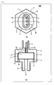
- Figs. 1A and 1B are diagrams depicting a configuration of a pressure sensor 100 according to Embodiment 1 of this invention.
- FIGs. 1A and 1B are diagrams depicting a configuration of the pressure sensor 100 according to Embodiment 1 of this invention.
- Fig. 1A is a plan view of a main part
- Fig. 1B is a cross-sectional view of the main part sectioned at the X-X line in Fig. 1A .
- This pressure sensor 100 has a socket portion 1 and a nut portion 2 having a hexagonal planar shape, which are integrally molded with resin, a screw portion 6 which is tightly bonded to a side wall 4 of an opening of a concave part 3 of the nut portion 2 with the adhesive 5, and a sense element 7 which is fixed to a pedestal 24 of the screw portion 6, and is disposed in the concave part 3 of the nut portion 2.
- the socket portion 1, the nut portion 2 and the screw portion 6 constitute a package 8.
- the socket portion 1 is a portion of connection with external wiring (not illustrated).
- a through hole 9 to introduce pressure measurement target fluid is formed in the screw portion 6, and an external lead-out terminal 10 is fixed to the sense element 7.
- the external lead-out terminal 10 passes through a through hole 11 which is formed from a base 3a of the concave part 3 to the socket portion 1, and is tightly fixed to the socket portion 1 with the adhesive 12, so as to be a connection terminal to connect the external wiring (not illustrated).
- Fig. 2 is a cross-sectional view of a main part of the sense element 7 in Fig. 1B .
- the sense element 7 has a metal support portion 15, a semiconductor strain gauge type pressure sensor element 17, a metal diaphragm 19, the above-mentioned external lead-out terminal 10, and liquid 21 that transfers pressure to the pressure sensor element 17.
- the support portion 15 has a concave part 14 constituting a housing box 13 (hereafter called "concave part of the housing box 13").
- the pressure sensor element 17, which senses pressure is an element that is supported by a glass substrate 16.
- the glass substrate 16 is fixed to a base 14a of the concave part 14 of the housing box 13.
- the external lead-out terminal 10 is connected with the pressure sensor element 17 via a bonding wire 20, and passes through the housing box 13. Further, the external lead-out terminal 10 is fixed to the housing box 13 by an insulating member 23 that blocks a through hole 22.
- the insulating member 23 is made of glass, for example.
- the diaphragm 19 blocks an opening 18 of the concave part 14 of the housing box 13, and constitutes the housing box 13.
- the diaphragm 19 is a wavy thin metal plate.
- the liquid 21 fills the concave part 14 of the housing box 13.
- the pressure sensor element 17 may be a capacitor type.
- the sealability inside the package 8 improves by integrally molding the socket portion 1 and the nut portion 2 constituting the package 8 with resin, and bonding the screw portion 6 and the nut portion 2 with the adhesive 5. Improvement of the sealability inside the package 8 enhances the reliability of the sense element 7 disposed inside the package 8, and implements a highly reliable pressure sensor 100.
- the nut portion 2 and the screw portion 6 are bonded with the adhesive 5, therefore the fixing strength between the nut portion 2 and the screw portion 6 with the adhesive 5 is stably secured.
- the gap M between the nut portion 2 and the screw portion 6 is filled with the adhesive 5
- the gap N between the external lead-out terminal 10 and the socket portion 1 is filled with the adhesive 12, hence the entry of water or the like into the gaps M and N is prevented, and a highly reliable pressure sensor 100 can be implemented.
- the socket portion 1 and the nut portion 2 are integrally molded, which decreases the manufacturing man-hours and reduces the manufacturing cost of the pressure sensor 100. Since the nut portion 2 is made of resin, the number of metal members decreases, cost is reduced, and the influence of market price fluctuations can be mitigated.
- the planar shape of the nut portion 2 is a hexagon, assuming that a commercial tool is used, but shape is not limited to a hexagon. If a dedicated tool is used, the planar shape of the nut portion 2 may be any polygonal shape, such as a square or pentagon. Any planar shape can be easily formed since the nut portion 2 is molded with resin.
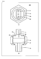
- Figs. 3A and 3B are diagrams depicting a first method to prevent slipping between the nut portion 2 and the screw portion 6 in Figs. 1A and 1B in the rotation direction.
- Fig. 3A is a cross-sectional view of a main part where the rough surface 25 is formed on the pedestal 24 of the screw portion 6 by knurling
- Fig. 3B is a perspective view of the main part where concave parts 26 are formed on the side wall 4 of the opening of the concave part 3 of the nut portion 2.
- the concave part (groove) 26 illustrated in Fig. 3B is formed vertical to the opening surface of the opening of the concave part 3 of the nut portion 2, but the form is not limited to this, and a plurality of concave parts, which are inclined from the opening surface of the opening of the concave part 3 in one direction at a predetermined angle, or a screw structure, may be used.
- the adhesive 5 enters the knurled rough surface 25 on the side face of the pedestal 24, which is disposed on one end of the screw portion 6, and the concave parts 26 formed on the side wall 4 of the opening of the concave part 3 of the nut portion 2, whereby the bonding of the adhesive 5 and the nut portion 2 increases.
- slip-rotation of the nut portion 2 when the nut portion 2 is rotated, can be prevented, and the rotational force applied to the nut portion 2 is transferred to the screw portion 6 with certainty.
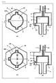
- Figs. 4A to 4D are diagrams depicting a second method to prevent slipping between the nut portion 2 and the screw portion 6 in Figs. 1A and 1B in the rotation direction.
- Figs. 4A and 4B are a plan view and a cross-sectional view depicting a configuration where convex parts 27 are formed on a side wall of the pedestal 24 of the screw portion 6.
- Figs. 4C and 4D are a plan view and a cross-sectional view depicting a configuration where convex parts 29 are formed on the side wall of the sense element 7.
- Figs. 4B and 4D are cross-sectional views of the entire sensor sectioned in the X-X line in Figs. 4A and 4C respectively.
- the convex parts 27 are formed on the side wall of the pedestal 24 of the screw portion 6, and the concave parts 28, to which the convex part 27 are fitted, are formed on the side wall 4 of the opening of the concave part 3 of the nut portion 2, whereby the rotational force applied to the nut portion 2 can be transferred to the screw portion 6 with certainty.
- the convex parts 29 are formed on the side wall of the sense element 7, and the concave parts 28a, to which the convex parts 29 are fitted, are formed on the side wall 4 of the opening of the concave part 3 of the nut portion 2. Since the sense element 7 is firmly fixed to the screw portion 6 by welding or the like, the rotational force applied to the nut portion 2 via the sense element 7 can be transferred to the screw portion 6 with certainty. In this example, three convex parts 27 or 29 are formed, but the present invention is not limited to this number. Further, in the Figs.
- the convex parts 29 are formed only around the opening of the concave part 14 of the housing box 13 of the sense element 7 illustrated in Fig. 2 , but the convex parts 29 may be formed from the opening of the concave part 14 of the housing box 13 to the base 14a of the housing box 13.
- Figs. 5A to 5D are diagrams depicting a third method to prevent slipping between the nut portion 2 and the screw portion 6 in Figs. 1A and 1B in the rotation direction.
- Fig. 5A is a plan view of a main part where the planar shape of the pedestal 24 of the screw portion 6 is a hexagon
- Fig. 5C is a plan view of a main part where the planar shape of the convex part 30 in the lower part of the side wall of the sense element 7 is a hexagon
- Figs. 5B and 5D are cross-sectional views of the entire sensor sectioned in the X-X line in Figs. 5A and 5C respectively.
- the planar shape of the pedestal 24 of the screw portion 6 is a hexagon
- the planar shape of the concave part 3 of the nut portion 2 is a hexagon so as to fit with the pedestal 24.
- the planar shape of the convex part 30 in the lower part of the side wall of the sense element 7 is a hexagon
- the planar shape of the concave part 3 of the nut portion 2 is a hexagon, so as to fit with the convex part 30.
- Figs. 5C and 5D only the planar shape around the opening of the concave part 14 of the housing box 13 of the sense element 7 illustrated in Fig. 2 is a hexagon, but the planar shape of the entire housing box 13 may be a hexagon.
- the planar shape is not limited to a hexagon, but may be such a polygon as a pentagon or an octagon to acquire a similar effect.
- the fixing strength of the screw portion and the nut portion, and the sealability inside the package improve by bonding the screw portion and the nut portion with adhesive, whereby reliability can be enhanced.
- the socket portion and the nut portion are integrally molded, hence manufacturing man-hours can be decreased and manufacturing cost can be reduced.
- the nut portion is made of resin, hence the number of metal members decreases, and cost is reduced compared to the prior art.
- FIGS. 6A to 6C are cross-sectional views of the main part manufacturing steps, depicting the method of manufacturing the pressure sensor 100 according to Embodiment 2 of this invention in sequence.
- the socket portion 1 and the nut portion 2 are integrally molded with resin.
- the resin is, for example, a plastic called PPS (Poly Phenylene Sulfide) or an engineered plastic, and is preferably a material of which mechanical strength is close to metal and has non-thermoplasticity, which does not deform even at a temperature of around 150°C.
- the sense element 7 is fixed to the pedestal 24 of the metal screw portion 6.
- the sense element 7 is fixed to the pedestal 24 of the screw portion 6 by laser welding or plasma welding, for example.
- the external lead-out terminal 10 is fixed in advance.
- the screw portion 6 is inserted into the concave part 3 of the nut portion 2, so that the external lead-out terminal 10 passes through the through hole 11 of the socket portion 1, and the screw portion 6 is fitted to the concave part 3 of the nut portion 2.
- the side face of the pedestal 24 of the screw portion 6 and the side wall 4 of the opening of the concave part 3 of the nut portion 2 are tightly fixed with the adhesive 5.
- the adhesive 12 is filled in the through hole 11 of the socket portion 1, so as to tightly fix the external lead-out terminal 10.
- Embodiment 2 As described above, according to Embodiment 2, an effect similar to the case of Embodiment 1 can be obtained.
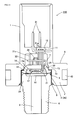
- Fig. 11 is a cross-sectional view depicting a configuration of a pressure sensor 110 according to Embodiment 3.
- Figs. 12A and 12B are perspective views depicting a pre-assembly state of the pressure sensor 110 in Fig. 11 .
- Figs. 13A and 13B are perspective views depicting a configuration of the socket portion 1 of the pressure sensor 110 in Fig. 11 .
- Fig. 14 is a perspective view depicting an internal configuration of the socket portion 1 of the pressure sensor 110 in Fig. 11 .
- a difference of the pressure sensor 110 according to Embodiment 3 from the pressure sensor according to Embodiment 1 is that the concave part 3 of the nut portion 2 includes a base 3a, and an adhesive injection portion (groove) 34 to inject the adhesive 5 is formed from the side wall 4 of the opening of the concave part 3 to the base 3a.
- the plurality of adhesive injection portions 34 are disposed on the side wall 4 of the opening of the concave part 3 of the nut portion 2, so that when the screw portion 6 is inserted into the concave part 3 of the nut portion 2, a gap is generated between the side wall 4 of the opening of the concave part 3 of the nut portion 2, and the pedestal 24 of the screw portion 6 and the housing box 13 fixed to the screw portion 6.
- the adhesive injection portion 34 is a groove that extends from an opening edge on the side opposite to the base 3a of the concave part 3 of the nut portion 2 toward the base 3a.
- the adhesive 5 injected into the adhesive injection portion 34 can reach the base 3a of the concave part 3 of the nut portion 2 after the screw portion 6 is inserted into the concave part 3 of the nut portion 2. Thereby the base 3a of the concave part 3 and the upper surface of the housing box 13 can be bonded. As a result, the area of adhesion between the concave part 3 of the nut portion 2 and the pedestal 24 of the screw portion 6 and the housing box 13 by the adhesive 5 after solidification can be enlarged, and the fixing strength between the nut portion 2 and the screw portion 6 can be improved.
- the fixing strength between the nut portion 2 and the screw portion 6 determines the fixing strength of the sense element 7 with respect to the tightening torque of the screw portion 6.
- the sense element 7 can be attached to the measurement object body with certainty, and leakage of the pressure medium can be prevented.
- the nut portion 2, which is molded with resin has a thick wall part, then pits and cavities may form in the nut portion 2. Therefore a groove 35 of which depth is the height direction of the nut portion 2 may be formed, or a groove 40 may be formed on each surface of the nut portion 2, so that a thick wall part is not formed in the nut portion 2 when the nut portion 2 is molded.
- Terminals 31a connected to the pressure sensor element 17 are a power supply terminal, a ground terminal and an output terminal. Each terminal 31a is connected to each external lead-out terminal 31 disposed in the socket portion 1 respectively, thereby forming an external lead-out terminal. In Fig. 11 , one external lead-out terminal 31 is not illustrated, but a same number of external lead-out terminals 31 as the number of terminals 31a are disposed according to this embodiment.
- the terminals 31b and 31c connected to the pressure sensor element 17 are a characteristic adjustment terminal and a trimming terminal respectively. The terminal 31b is shorter than the terminal 31a, for example.
- a noise countermeasure substrate 33 having a chip capacitor 36 may be disposed between the pressure sensor element 17 and the socket portion 1.
- a terminal 31c having approximately the same length as the terminals 31a may be disposed to pass through the through hole 37 of the chip capacitor 36.
- the terminal 31c has a function to fix the position of the noise countermeasure substrate 33 and to determine the position of the noise countermeasure substrate 33 with respect to the socket portion 1.
- the chip capacitor 36 is connected to the terminal 31a via a wiring pattern 38 of the noise countermeasure substrate 33.
- the reference numeral 32 denotes a sealing copper wire to block a hole, which is used for injecting such liquid 21 as oil into the sense element 7, by welding.
- the insulating member 23 is formed by melting a glass tube.
- the diaphragm 19 and the pedestal 24 of the screw portion 6 the diaphragm 19 is sandwiched between the pedestal 24 of the screw portion 6 and the housing box 13, and an area around the stacked part of the housing box 13, the diaphragm 19 and the pedestal 24 of the screw portion 6 is welded, for example.
- the distance between the pedestal 24 of the screw portion 6 and the housing box 13 may increase in the outward direction when the diaphragm 19 is sandwiched between the pedestal 24 and the housing box 13, and is secured.
- the pressure sensor element 17 and the glass substrate 16 are joined by electrostatic joining.
- the pressure sensor element 17 is fixed to the base 14a of the concave part 14 by adhesive (not illustrated) constituting the housing box 13.
- the rough surface shown in Fig. 3A may be formed on the side wall of the pedestal 24.
- FIG. 15 is a cross-sectional view depicting a configuration of an acceleration sensor 120 according to Embodiment 4.
- the physical quantity sensor according to Embodiment 4 is the acceleration sensor 120, to which the configuration of the pressure sensor 100 of Embodiment 1 is applied.
- a difference of the acceleration sensor 120 of Embodiment 4 from the pressure sensor 100 of Embodiment 1 is that the through hole, to introduce pressure to a screw portion 46 for fixing the sense element 47, is not formed in a concave part 43 of the nut portion 42.
- the other configuration of a package 48 of the acceleration sensor 120 of Embodiment 4 constituted by the socket portion 41, the nut portion 42 and the screw portion 46, and the internal configuration of the sense element 47 (not illustrated) are the same as the package and the sense element of the pressure sensors according to Embodiments 1 to 3.
- the reference numeral 49 denotes an external lead-out terminal
- the reference numerals 43a and 44 denote a base and a side wall of the opening of the concave part 43 of the nut portion 42 respectively
- the reference numeral 45 denotes adhesive.
- the physical quantity sensor and the method of manufacturing the physical sensor according to this invention are useful for physical quantity sensors including pressure sensors and acceleration sensors, which are used for automobiles and industrial apparatuses.
Landscapes
- Physics & Mathematics (AREA)
- General Physics & Mathematics (AREA)
- Engineering & Computer Science (AREA)
- Plasma & Fusion (AREA)
- Mechanical Engineering (AREA)
- Optics & Photonics (AREA)
- Health & Medical Sciences (AREA)
- Child & Adolescent Psychology (AREA)
- Thermal Sciences (AREA)
- Measuring Fluid Pressure (AREA)
Abstract
Description
- The present invention relates to a physical quantity sensor, such as a pressure sensor and an acceleration sensor, and a method of manufacturing the physical quantity sensor.
- Many physical quantity sensors are used for automobiles and industrial apparatuses. Physical quantity sensors include pressure sensors and acceleration sensors, which are often used in harsh environments exhibiting high temperatures and high humidities. First a conventional pressure sensor is described.
-
Figs. 7A and 7B are a plan view and a cross-sectional view of a main part of a firstconventional pressure sensor 500. Thepressure sensor 500 is constituted by asocket portion 51, ahexagonal nut portion 52, ascrew portion 56, and asense element 57, and thehexagonal nut portion 52 and thescrew portion 56 are integrated. - The
socket portion 51, where asignal terminal 60 for extracting sensor signals is installed, is formed by resin molding. Thesense element 57 is sandwiched by theresin socket portion 51 and themetal screw portion 56, and thesocket portion 51 is caulked by acaulking portion 52a that is attached to thehexagonal nut portion 52, so that thesense element 57 is secured. This structure is the same as the structure ofPatent Document 1. -
Figs. 8A and 8B are a plan view and a cross-sectional view of a main part of a secondconventional pressure sensor 600. A difference from thepressure sensor 500 inFigs. 7A and 7B is that a metalhexagonal nut portion 62 and ascrew portion 66 are separated, and asocket portion 61, thescrew portion 66 and thehexagonal nut portion 62 are formed independently from one another. Thescrew portion 66
is separated from thehexagonal nut portion 62 because the material of thescrew portion 66 may be different in some cases depending on intended use. Thesense element 57, theresin socket portion 61 and themetal screw portion 66 are held together by thehexagonal nut portion 62, and are caulked respectively by thecaulking portion 62a that is attached to the upper part and the lower part of thehexagonal nut portion 62. -
Figs. 9A and 9B are a plan view and a cross-sectional view of a main part of a thirdconventional pressure sensor 700. A difference from thepressure sensor 600 inFigs. 8A and 8B is that ametal screw portion 76 and a metalhexagonal nut portion 72 are separated but integrated by brazing or welding. This configuration is for transferring the rotational force of thehexagonal nut portion 72 to thescrew portion 76 with certainty. Thesocket portion 71, thesense element 57 and thescrew portion 76 are secured by caulking acaulking portion 72a, attached to the upper part of thehexagonal nut portion 72, toward thesocket portion 71. -
Fig. 10 is a cross-sectional view of a main part of eachsense element 57 inFigs. 7B ,8B and9B . Thesense element 57 inFig. 10 has a configuration for use in a semiconductor type pressure sensor. Thissense element 57 is constituted by a semiconductor strain gauge typepressure sensor element 67, ametal housing box 63 which houses thepressure sensor element 67 and has adiaphragm 69, an external lead-out terminal (terminal for external connection) 60 that passes through thehousing box 63, and aninsulating resin 83 that blocks a throughhole 82 where the external lead-outterminal 60 passes through. Thepressure sensor element 67 and the external lead-outterminal 60 are connected by abonding wire 70. For thepressure sensor element 67, a capacitor type pressure sensor may be used, although this is not illustrated. - To mount the
pressure sensor metal screw portion hexagonal nut portion - In this way, the rotational torque is applied to the
screw portion hexagonal nut portion pressure sensor screw portion screw portion screw portion hexagonal nut portion screw portion hexagonal nut portion screw portion hexagonal nut portion metal screw portion hexagonal nut portion - To fabricate the
metal screw portion hexagonal nut portion screw portion hexagonal nut portion - The pressure sensor disclosed in
Patent Document 1 includes a metal body (the hexagonal nut portion integrated with the screw portion) where a through hole is created, and a sense element is installed on the body. The sense element includes a resin base and a metal pressure introduction pipe which has an inflow port where measurement target fluid flows in, and is fixed to the base such that the base end of the pressure introduction pipe is disposed on one side of the through hole. Further, the sense element includes a pressure sensor element that is tightly fixed to the end face of the base end of the pressure introduction pipe and converts the pressure into an electric signal by blocking the inflow port. The sense element also has a terminal which is electrically connected with the pressure sensor element, and is fixed to the base. The pressure sensor disclosed inPatent Document 1 is a pressure sensor that includes a sense element having this configuration, and which measures the pressure of the fluid, wherein a side wall of the through hole and the outer periphery of the pressure introduction pipe are joined airtight (joint portion). Thereby a pressure sensor which can decrease the temperature characteristic measuring time of the pressure sensor element required for temperature compensation can be provided. InPatent Document 1, the socket portion (connector portion) is made of resin, and the hexagonal nut portion (body) is made of metal. In other words,Patent Document 1 corresponds toFigs. 7A and 7B . - Patent Document 1: Japanese Patent Application Laid-Open No.
H9-178595 - However, as described above, expensive metal (brass and stainless steel) is often used as a material of the
hexagonal nut portion screw portion pressure sensor Figs. 7A to 9B . Therefore it is very difficult to stabilize material cost due to the influence of market price fluctuations of metal materials. - Further, in fabrication of the
hexagonal nut portion screw portion - Moreover, according to the configuration of the
pressure sensor Figs. 7A to 9B , thesense element 57 is sandwiched by thesocket portion screw portion sense element 57 is secured by caulking performed by thecaulking portion hexagonal nut portion sense element 57 depends on the fabrication dimensions of thecaulking portion hexagonal nut portion sense element 57 with a stable force is difficult. This causes a quality dispersion of thepressure sensor - The
caulking portion hexagonal nut portion resin socket portion hexagonal nut portion socket portion hexagonal nut portion screw portion dotted line 80 inFig. 10 indicates, when such liquid as water adheres to themetal housing box 63 constituting thesense element 57, thehousing box 63 corrodes, and when the liquid adheres to an area of thehousing box 63 where the external lead-outterminal 60 passes through, insulation between the external lead-outterminal 60 and themetal housing box 63 becomes difficult. - On the other hand, if the sealability inside the package is improved by coating the contact area of the
caulking portion hexagonal nut portion socket portion hexagonal nut portion screw portion Figs. 7B ,8B and9B using dottedlines 81, manufacturing cost increases. - In the configuration of
Patent Document 1 as well, the resin socket portion and the metal hexagonal nut portion are separated, therefore sealability inside the package is low, and manufacturing cost is high since metal is used for the hexagonal nut portion and the screw portion. - To solve the above problems of the prior art, it is an object of the present invention to provide a physical quantity sensor that can reduce cost, and a method of manufacturing the physical quantity sensor.
- To solve the above-mentioned problems and to achieve the object of the present invention, a physical quantity sensor according to this invention has: a package that includes a socket portion, a nut portion and a screw portion; and a sense element, and has the following characteristics. The socket portion is a portion of connection with external wiring. Rotational force, that is a mounting torque, is transferred from a tool to the nut portion. And the rotational force is transferred from the nut portion to the screw portion. The screw portion has an introduction hole introducing pressure measurement target gas or pressure measurement target liquid, and has a pedestal on one end of the introduction hole. The sense element is fixed to the pedestal so as to block the introduction hole, and is housed in a concave part of the nut portion. The socket portion and the nut portion are an integrated resin member. And the screw portion is a metal member. An inner side wall of the concave part of the nut portion and a side wall of the pedestal are bonded with adhesive.
- In the physical quantity sensor according to this invention, it is preferable that the sense element includes an element that senses pressure or acceleration, a housing box which houses the element, and a terminal which is electrically connected with the element, and is disposed passing through the housing box.
- In the physical quantity sensor according to this invention, it is preferable that the side wall of the pedestal has a rough surface. In the physical quantity sensor according to this invention, it is preferable that a groove, extending in a direction from an opening edge on the side opposite to a base toward the base, is provided on the inner side wall face of the concave part of the nut portion.
- In the physical quantity sensor according to this invention, it is preferable that a convex part or a concave part is provided on the side wall of the pedestal, and a concave part or a convex part, to which the convex part or the concave part on the side wall of the pedestal is fitted, is provided on an inner side wall face of the concave part of the nut portion.
- In the physical quantity sensor according to this invention, it is preferable that a planar shape of the concave part of the nut portion is a polygon, and a planar shape of the pedestal is a polygon that is fitted to the concave part of the nut portion.
- In the physical quantity sensor according to this invention, it is preferable that a planar shape is a polygon from the opening edge on the side opposite to the base of the concave part of the nut portion to a predetermined depth, and a planar shape of the sense element is a polygon that is fitted to the area of the concave part of the nut portion where the planar shape is the polygon.
- In the physical quantity sensor according to this invention, it is preferable that the nut portion and the sense element are bonded by fitting the concave part of the nut portion to at least a part of the sense element, and filling adhesive into a gap formed in the fitted portion.
- To solve the above-mentioned problems and to achieve the object of the present invention, a physical quantity sensor according to this invention has: a package including a socket portion, a nut portion and a screw portion; and a sense element, and has the following characteristics. The socket portion is a portion of connection with external wiring. Rotational force, that is a mounting torque, is transferred from a tool to the nut portion. The rotational force is transferred from the nut portion to the screw portion, and the screw portion has a pedestal on one end thereof. The sense element is disposed on the pedestal. The socket portion and the nut portion are an integrated resin member. The screw portion is a metal member. An inner side wall of the concave part of the nut portion and a side wall of the pedestal are bonded with adhesive.
- In the physical quantity sensor according to the invention, it is preferable that the screw portion has an introduction hole introducing pressure measurement target gas or pressure measurement target liquid. The sense element includes a metal diaphragm, a metal housing box and an element housed in the housing box. The diaphragm is welded to the pedestal so as to block the introduction hole. The housing box is welded to the diaphragm so as to form a space inside the sense element. Suitably, the space may be filled with liquid.
- In the physical quantity sensor according to this invention, it is preferable that the side wall of the pedestal has a rough surface. In the physical quantity sensor according to this invention, it is preferable that a groove, extending in a direction from the opening-edge on the side opposite to a base toward the base, exists on the inner side wall face of the concave part of the nut portion.
- In the physical quantity sensor according to this invention, it is preferable that a step is formed on the inner side wall of the concave part of the nut portion at the opening edge on the side opposite to the base on the socket portion side, and the step makes the opening width of the opening edge on the side opposite to the base of the concave part of the nut portion to be wider than the opening width on the base side. In the physical quantity sensor according to this invention, it is preferable that the upper surface of the sense element is bonded to the step with adhesive.
- In the physical quantity sensor according to this invention, it is preferable that a step is formed on the inner side wall of the concave part of the nut portion at the opening edge on the side opposite to the base on the socket portion side, and the step makes the opening width of the opening edge on the side opposite to the base of the concave part of the nut portion to be wider than the opening width on the base side. In the physical quantity sensor according to this invention, it is preferable that the upper surface of the sense element is bonded to the step with adhesive.
- To solve the above-mentioned problems and to achieve the object of the present invention, a method of manufacturing the physical quantity sensor according to this invention has the following characteristics. First a step of integrally molding the socket portion and the nut portion with resin is performed. Then a step of fixing the sense element to the surface of the metal screw portion is performed. Then a step of fitting the screw portion to the concave part of the nut portion, and bonding the screw portion and the nut portion with adhesive is performed.
- In the method of manufacturing the physical quantity sensor according to this invention, it is preferable that the sense element is fixed to the surface of the screw portion by laser welding or plasma welding.
- To solve the above-mentioned problems and to achieve the object of the present invention, a method of manufacturing the physical quantity sensor according to this invention has the following characteristics. First a step of integrally molding the socket portion and the nut portion with resin is performed. Then a step of fixing the diaphragm and the housing box to the screw portion by welding the screw portion, the diaphragm and the housing box in a state where the housing box is stacked onto the surface of the screw portion via the diaphragm is performed. Then a step of fitting the screw portion to the concave part of the nut portion, and bonding the screw portion and the nut portion with adhesive is performed.
- According to the physical quantity sensor and the method of manufacturing the physical quantity sensor according to this invention, the socket portion and the nut portion are integrally molded with resin, and the screw portion and the nut portion are bonded with adhesive, whereby physical quantity sensors, such as a pressure sensor and an acceleration sensor, with better sealability inside a package, can be provided at low cost.
-
Figs. 1A and 1B are diagrams depicting a configuration of apressure sensor 100 according toEmbodiment 1 of this invention; -
Fig. 2 is a cross-sectional view of a main part of asense element 7 inFig. 1B ; -
Figs. 3A and 3B are diagrams depicting a first method to prevent slipping between thenut portion 2 and thescrew portion 6 inFigs. 1A and 1B in the rotation direction; -
Figs. 4A to 4D are diagrams depicting a second method to prevent slipping between thenut portion 2 and thescrew portion 6 inFigs. 1A and 1B in the rotation direction; -
Figs. 5A to 5D are diagrams depicting a third method to prevent slipping between thenut portion 2 and thescrew portion 6 inFigs. 1A and 1B in the rotation direction; -
Figs. 6A to 6C are cross-sectional views of main part manufacturing steps depicting the method of manufacturing thepressure sensor 100 according toEmbodiment 2 of this invention in sequence; -
Figs. 7A and 7B are a plan view and a cross-sectional view of a main part of a firstconventional pressure sensor 500; -
Figs. 8A and 8B are a plan view and a cross-sectional view of a main part of a secondconventional pressure sensor 600; -
Figs. 9A and 9B are a plan view and a cross-sectional view of a main part of a thirdconventional pressure sensor 700; -
Fig. 10 is a cross-sectional view of a main part of thesense element 57 inFigs. 7B ,8B and9B ; -
Fig. 11 is a cross-sectional view depicting a configuration of apressure sensor 110 according toEmbodiment 3 of this invention; -
Figs. 12A and 12B are perspective views depicting a pre-assembly state of thepressure sensor 110 inFig. 11 ; -
Figs. 13A and 13B are perspective views depicting a configuration of thesocket portion 1 of thepressure sensor 110 inFig. 11 ; -
Fig. 14 is a perspective view depicting an internal configuration of thesocket portion 1 of thepressure sensor 110 inFig. 11 ; and -
Fig. 15 is a cross-sectional view depicting a configuration of anacceleration sensor 120 according toEmbodiment 4 of this invention. - Preferred embodiments of a physical quantity sensor and a method of manufacturing the physical quantity sensor according to this invention will now be described with reference to the accompanying drawings. In the following description of the embodiments and the accompanying drawings, the same composing elements are denoted with the same reference symbols, and redundant description thereof is omitted. In the following description, a pressure sensor is described as an example of the physical quantity sensor, but the present invention can be applied to an acceleration sensor or the like as well.
- A physical quantity sensor according to
Embodiment 1 will be described using a pressure sensor as an example.Figs. 1A and 1B are diagrams depicting a configuration of thepressure sensor 100 according toEmbodiment 1 of this invention.Fig. 1A is a plan view of a main part, andFig. 1B is a cross-sectional view of the main part sectioned at the X-X line inFig. 1A . - This
pressure sensor 100 has asocket portion 1 and anut portion 2 having a hexagonal planar shape, which are integrally molded with resin, ascrew portion 6 which is tightly bonded to aside wall 4 of an opening of aconcave part 3 of thenut portion 2 with the adhesive 5, and asense element 7 which is fixed to apedestal 24 of thescrew portion 6, and is disposed in theconcave part 3 of thenut portion 2. Thesocket portion 1, thenut portion 2 and thescrew portion 6 constitute apackage 8. Thesocket portion 1 is a portion of connection with external wiring (not illustrated). A throughhole 9 to introduce pressure measurement target fluid is formed in thescrew portion 6, and an external lead-outterminal 10 is fixed to thesense element 7. The external lead-out terminal 10 passes through a throughhole 11 which is formed from abase 3a of theconcave part 3 to thesocket portion 1, and is tightly fixed to thesocket portion 1 with the adhesive 12, so as to be a connection terminal to connect the external wiring (not illustrated). -
Fig. 2 is a cross-sectional view of a main part of thesense element 7 inFig. 1B . Thesense element 7 has ametal support portion 15, a semiconductor strain gauge typepressure sensor element 17, ametal diaphragm 19, the above-mentioned external lead-out terminal 10, and liquid 21 that transfers pressure to thepressure sensor element 17. Thesupport portion 15 has aconcave part 14 constituting a housing box 13 (hereafter called "concave part of thehousing box 13"). Thepressure sensor element 17, which senses pressure, is an element that is supported by aglass substrate 16. Theglass substrate 16 is fixed to abase 14a of theconcave part 14 of thehousing box 13. - The external lead-out
terminal 10 is connected with thepressure sensor element 17 via abonding wire 20, and passes through thehousing box 13. Further, the external lead-outterminal 10 is fixed to thehousing box 13 by an insulatingmember 23 that blocks a throughhole 22. The insulatingmember 23 is made of glass, for example. Thediaphragm 19 blocks anopening 18 of theconcave part 14 of thehousing box 13, and constitutes thehousing box 13. Thediaphragm 19 is a wavy thin metal plate. The liquid 21 fills theconcave part 14 of thehousing box 13. Thepressure sensor element 17 may be a capacitor type. - As mentioned above, the sealability inside the
package 8 improves by integrally molding thesocket portion 1 and thenut portion 2 constituting thepackage 8 with resin, and bonding thescrew portion 6 and thenut portion 2 with the adhesive 5. Improvement of the sealability inside thepackage 8 enhances the reliability of thesense element 7 disposed inside thepackage 8, and implements a highlyreliable pressure sensor 100. - Further, the
nut portion 2 and thescrew portion 6 are bonded with the adhesive 5, therefore the fixing strength between thenut portion 2 and thescrew portion 6 with the adhesive 5 is stably secured. Moreover, the gap M between thenut portion 2 and thescrew portion 6 is filled with the adhesive 5, and the gap N between the external lead-outterminal 10 and thesocket portion 1 is filled with the adhesive 12, hence the entry of water or the like into the gaps M and N is prevented, and a highlyreliable pressure sensor 100 can be implemented. - Furthermore, the
socket portion 1 and thenut portion 2 are integrally molded, which decreases the manufacturing man-hours and reduces the manufacturing cost of thepressure sensor 100. Since thenut portion 2 is made of resin, the number of metal members decreases, cost is reduced, and the influence of market price fluctuations can be mitigated. - The planar shape of the
nut portion 2 is a hexagon, assuming that a commercial tool is used, but shape is not limited to a hexagon. If a dedicated tool is used, the planar shape of thenut portion 2 may be any polygonal shape, such as a square or pentagon. Any planar shape can be easily formed since thenut portion 2 is molded with resin. -
Figs. 3A and 3B are diagrams depicting a first method to prevent slipping between thenut portion 2 and thescrew portion 6 inFigs. 1A and 1B in the rotation direction. -
Fig. 3A is a cross-sectional view of a main part where the rough surface 25 is formed on thepedestal 24 of thescrew portion 6 by knurling, andFig. 3B is a perspective view of the main part whereconcave parts 26 are formed on theside wall 4 of the opening of theconcave part 3 of thenut portion 2. The concave part (groove) 26 illustrated inFig. 3B is formed vertical to the opening surface of the opening of theconcave part 3 of thenut portion 2, but the form is not limited to this, and a plurality of concave parts, which are inclined from the opening surface of the opening of theconcave part 3 in one direction at a predetermined angle, or a screw structure, may be used. - The adhesive 5 enters the knurled rough surface 25 on the side face of the
pedestal 24, which is disposed on one end of thescrew portion 6, and theconcave parts 26 formed on theside wall 4 of the opening of theconcave part 3 of thenut portion 2, whereby the bonding of the adhesive 5 and thenut portion 2 increases. As a result, slip-rotation of thenut portion 2, when thenut portion 2 is rotated, can be prevented, and the rotational force applied to thenut portion 2 is transferred to thescrew portion 6 with certainty. -
Figs. 4A to 4D are diagrams depicting a second method to prevent slipping between thenut portion 2 and thescrew portion 6 inFigs. 1A and 1B in the rotation direction.Figs. 4A and 4B are a plan view and a cross-sectional view depicting a configuration whereconvex parts 27 are formed on a side wall of thepedestal 24 of thescrew portion 6.Figs. 4C and 4D are a plan view and a cross-sectional view depicting a configuration whereconvex parts 29 are formed on the side wall of thesense element 7.Figs. 4B and 4D are cross-sectional views of the entire sensor sectioned in the X-X line inFigs. 4A and 4C respectively. - In
Figs. 4A and 4B , theconvex parts 27 are formed on the side wall of thepedestal 24 of thescrew portion 6, and theconcave parts 28, to which theconvex part 27 are fitted, are formed on theside wall 4 of the opening of theconcave part 3 of thenut portion 2, whereby the rotational force applied to thenut portion 2 can be transferred to thescrew portion 6 with certainty. - In
Figs. 4C and 4D , theconvex parts 29 are formed on the side wall of thesense element 7, and theconcave parts 28a, to which theconvex parts 29 are fitted, are formed on theside wall 4 of the opening of theconcave part 3 of thenut portion 2. Since thesense element 7 is firmly fixed to thescrew portion 6 by welding or the like, the rotational force applied to thenut portion 2 via thesense element 7 can be transferred to thescrew portion 6 with certainty. In this example, threeconvex parts Figs. 4C and 4D , theconvex parts 29 are formed only around the opening of theconcave part 14 of thehousing box 13 of thesense element 7 illustrated inFig. 2 , but theconvex parts 29 may be formed from the opening of theconcave part 14 of thehousing box 13 to thebase 14a of thehousing box 13. -
Figs. 5A to 5D are diagrams depicting a third method to prevent slipping between thenut portion 2 and thescrew portion 6 inFigs. 1A and 1B in the rotation direction.Fig. 5A is a plan view of a main part where the planar shape of thepedestal 24 of thescrew portion 6 is a hexagon, andFig. 5C is a plan view of a main part where the planar shape of theconvex part 30 in the lower part of the side wall of thesense element 7 is a hexagon.Figs. 5B and 5D are cross-sectional views of the entire sensor sectioned in the X-X line inFigs. 5A and 5C respectively. - In
Figs. 5A and 5B , the planar shape of thepedestal 24 of thescrew portion 6 is a hexagon, and the planar shape of theconcave part 3 of thenut portion 2 is a hexagon so as to fit with thepedestal 24. By this configuration, the rotational force applied to thenut portion 2 can be transferred to thescrew portion 6 with certainty. - In
Figs. 5C and 5D , the planar shape of theconvex part 30 in the lower part of the side wall of thesense element 7 is a hexagon, and the planar shape of theconcave part 3 of thenut portion 2 is a hexagon, so as to fit with theconvex part 30. By this configuration, the rotational force applied to thenut portion 2 can be transferred to thescrew portion 6 with certainty. - In
Figs. 5C and 5D , only the planar shape around the opening of theconcave part 14 of thehousing box 13 of thesense element 7 illustrated inFig. 2 is a hexagon, but the planar shape of theentire housing box 13 may be a hexagon. - In
Figs. 5A to 5D , the planar shape is not limited to a hexagon, but may be such a polygon as a pentagon or an octagon to acquire a similar effect. - As described above, according to
Embodiment 1, the fixing strength of the screw portion and the nut portion, and the sealability inside the package improve by bonding the screw portion and the nut portion with adhesive, whereby reliability can be enhanced. Further, according toEmbodiment 1, the socket portion and the nut portion are integrally molded, hence manufacturing man-hours can be decreased and manufacturing cost can be reduced. Furthermore, according toEmbodiment 1, the nut portion is made of resin, hence the number of metal members decreases, and cost is reduced compared to the prior art. - A manufacturing method of a physical quantity sensor according to
Embodiment 2 will be described using a case of manufacturing thepressure sensor 100 illustrated inFigs. 1A and 1B as an example.Figs. 6A to 6C are cross-sectional views of the main part manufacturing steps, depicting the method of manufacturing thepressure sensor 100 according toEmbodiment 2 of this invention in sequence. - First in
Fig. 6A , thesocket portion 1 and thenut portion 2 are integrally molded with resin. The resin is, for example, a plastic called PPS (Poly Phenylene Sulfide) or an engineered plastic, and is preferably a material of which mechanical strength is close to metal and has non-thermoplasticity, which does not deform even at a temperature of around 150°C. - Then in
Fig. 6B , thesense element 7 is fixed to thepedestal 24 of themetal screw portion 6. Thesense element 7 is fixed to thepedestal 24 of thescrew portion 6 by laser welding or plasma welding, for example. In thesense element 7, the external lead-outterminal 10 is fixed in advance. Then inFig. 6C , thescrew portion 6 is inserted into theconcave part 3 of thenut portion 2, so that the external lead-out terminal 10 passes through the throughhole 11 of thesocket portion 1, and thescrew portion 6 is fitted to theconcave part 3 of thenut portion 2. Then the side face of thepedestal 24 of thescrew portion 6 and theside wall 4 of the opening of theconcave part 3 of thenut portion 2 are tightly fixed with the adhesive 5. Further, the adhesive 12 is filled in the throughhole 11 of thesocket portion 1, so as to tightly fix the external lead-outterminal 10. Thereby the manufacture of thepressure sensor 100 shown inFigs. 1A and 1B is completed. - As described above, according to
Embodiment 2, an effect similar to the case ofEmbodiment 1 can be obtained. - Now a configuration of a physical quantity sensor according to
Embodiment 3 of this invention will be described.Fig. 11 is a cross-sectional view depicting a configuration of apressure sensor 110 according toEmbodiment 3.Figs. 12A and 12B are perspective views depicting a pre-assembly state of thepressure sensor 110 inFig. 11 .Figs. 13A and 13B are perspective views depicting a configuration of thesocket portion 1 of thepressure sensor 110 inFig. 11 .Fig. 14 is a perspective view depicting an internal configuration of thesocket portion 1 of thepressure sensor 110 inFig. 11 . A difference of thepressure sensor 110 according toEmbodiment 3 from the pressure sensor according toEmbodiment 1 is that theconcave part 3 of thenut portion 2 includes abase 3a, and an adhesive injection portion (groove) 34 to inject the adhesive 5 is formed from theside wall 4 of the opening of theconcave part 3 to thebase 3a. - The plurality of
adhesive injection portions 34 are disposed on theside wall 4 of the opening of theconcave part 3 of thenut portion 2, so that when thescrew portion 6 is inserted into theconcave part 3 of thenut portion 2, a gap is generated between theside wall 4 of the opening of theconcave part 3 of thenut portion 2, and thepedestal 24 of thescrew portion 6 and thehousing box 13 fixed to thescrew portion 6. Theadhesive injection portion 34 is a groove that extends from an opening edge on the side opposite to thebase 3a of theconcave part 3 of thenut portion 2 toward thebase 3a. By forming theadhesive injection portion 34, the adhesive 5 injected into theadhesive injection portion 34 can reach thebase 3a of theconcave part 3 of thenut portion 2 after thescrew portion 6 is inserted into theconcave part 3 of thenut portion 2. Thereby thebase 3a of theconcave part 3 and the upper surface of thehousing box 13 can be bonded. As a result, the area of adhesion between theconcave part 3 of thenut portion 2 and thepedestal 24 of thescrew portion 6 and thehousing box 13 by the adhesive 5 after solidification can be enlarged, and the fixing strength between thenut portion 2 and thescrew portion 6 can be improved. - The fixing strength between the
nut portion 2 and thescrew portion 6 determines the fixing strength of thesense element 7 with respect to the tightening torque of thescrew portion 6. By improving the fixing strength between thenut portion 2 and thescrew portion 6 by forming theadhesive injection portion 34 as described above, thesense element 7 can be attached to the measurement object body with certainty, and leakage of the pressure medium can be prevented. Further, if thenut portion 2, which is molded with resin, has a thick wall part, then pits and cavities may form in thenut portion 2. Therefore agroove 35 of which depth is the height direction of thenut portion 2 may be formed, or agroove 40 may be formed on each surface of thenut portion 2, so that a thick wall part is not formed in thenut portion 2 when thenut portion 2 is molded. -
Terminals 31a connected to thepressure sensor element 17 are a power supply terminal, a ground terminal and an output terminal. Each terminal 31a is connected to each external lead-out terminal 31 disposed in thesocket portion 1 respectively, thereby forming an external lead-out terminal. InFig. 11 , one external lead-outterminal 31 is not illustrated, but a same number of external lead-outterminals 31 as the number ofterminals 31a are disposed according to this embodiment. Theterminals pressure sensor element 17 are a characteristic adjustment terminal and a trimming terminal respectively. The terminal 31b is shorter than the terminal 31a, for example. Anoise countermeasure substrate 33 having achip capacitor 36 may be disposed between thepressure sensor element 17 and thesocket portion 1. - Through
holes 37 for the terminal 31a to pass through are formed in thenoise countermeasure substrate 33, and thenoise countermeasure substrate 33 and theterminals 31a that pass through the throughholes 37 are soldered. A terminal 31c having approximately the same length as theterminals 31a may be disposed to pass through the throughhole 37 of thechip capacitor 36. The terminal 31c has a function to fix the position of thenoise countermeasure substrate 33 and to determine the position of thenoise countermeasure substrate 33 with respect to thesocket portion 1. Thechip capacitor 36 is connected to the terminal 31a via awiring pattern 38 of thenoise countermeasure substrate 33. Thereference numeral 32 denotes a sealing copper wire to block a hole, which is used for injecting such liquid 21 as oil into thesense element 7, by welding. - The insulating
member 23 is formed by melting a glass tube. To join thehousing box 13, thediaphragm 19 and thepedestal 24 of thescrew portion 6, thediaphragm 19 is sandwiched between thepedestal 24 of thescrew portion 6 and thehousing box 13, and an area around the stacked part of thehousing box 13, thediaphragm 19 and thepedestal 24 of thescrew portion 6 is welded, for example. To easily perform welding, the distance between thepedestal 24 of thescrew portion 6 and thehousing box 13 may increase in the outward direction when thediaphragm 19 is sandwiched between thepedestal 24 and thehousing box 13, and is secured. Thereby thehousing box 13, thediaphragm 19 and thepedestal 24 of thescrew portion 6 can be joined by performing welding only once. Thepressure sensor element 17 and theglass substrate 16 are joined by electrostatic joining. Thepressure sensor element 17 is fixed to thebase 14a of theconcave part 14 by adhesive (not illustrated) constituting thehousing box 13. - The rough surface shown in
Fig. 3A may be formed on the side wall of thepedestal 24. - As described above, according to
Embodiment 3, an effect similar to the case ofEmbodiment 1 can be obtained. - Now a configuration of a physical quantity sensor according to
Embodiment 4 of this invention will be described.Fig. 15 is a cross-sectional view depicting a configuration of anacceleration sensor 120 according toEmbodiment 4. The physical quantity sensor according toEmbodiment 4 is theacceleration sensor 120, to which the configuration of thepressure sensor 100 ofEmbodiment 1 is applied. A difference of theacceleration sensor 120 ofEmbodiment 4 from thepressure sensor 100 ofEmbodiment 1 is that the through hole, to introduce pressure to ascrew portion 46 for fixing thesense element 47, is not formed in aconcave part 43 of thenut portion 42. The other configuration of apackage 48 of theacceleration sensor 120 ofEmbodiment 4 constituted by thesocket portion 41, thenut portion 42 and thescrew portion 46, and the internal configuration of the sense element 47 (not illustrated) are the same as the package and the sense element of the pressure sensors according toEmbodiments 1 to 3. Thereference numeral 49 denotes an external lead-out terminal, and thereference numerals concave part 43 of thenut portion 42 respectively, and thereference numeral 45 denotes adhesive. - As described above, according to
Embodiment 4, an effect similar to the cases ofEmbodiments 1 to 3 can be obtained. - As described above, the physical quantity sensor and the method of manufacturing the physical sensor according to this invention are useful for physical quantity sensors including pressure sensors and acceleration sensors, which are used for automobiles and industrial apparatuses.
-
- 1, 41
- socket portion
- 2, 42
- nut portion
- 3, 43
- concave part of nut portion
- 3a, 43a
- bottom of concave part of nut portion
- 4, 44
- side wall of opening
- 5, 12, 45
- adhesive
- 6, 46
- screw portion
- 7, 47
- sense element
- 8, 48
- package
- 9, 11, 22
- through hole
- 10, 31, 49
- external lead-out terminal
- 13
- housing box
- 14
- concave part constituting housing box
- 14a
- base of concave part constituting housing box
- 15
- support portion
- 16
- glass substrate
- 17
- pressure sensor element
- 18
- opening of concave part constituting housing box
- 19
- diaphragm
- 20
- bonding wire
- 21
- liquid
- 23
- insulating member
- 24
- pedestal of screw portion
- 25
- rough surface of pedestal of screw portion
- 26, 28, 28a
- concave part of side wall of opening of concave part of nut portion
- 27
- convex part of side wall of pedestal of screw portion
- 29
- convex part of side wall of sense element
- 30
- convex part in lower part of side wall of sense element
- 100, 110
- pressure sensor
- 31a to 31c
- terminal
- 33
- noise countermeasure substrate
- 34
- adhesive injection portion
- 35
- groove
- 36
- chip capacitor
- 37
- through hole of noise countermeasure substrate
- 38
- wiring pattern of noise countermeasure substrate
- 100
- pressure sensor
- 120
- acceleration sensor
Claims (19)
- A physical quantity sensor, comprising:a package including a socket portion which is a portion of connection with an external wiring, a nut portion to which rotation force that is a mounting torque is transferred from a tool, and a screw portion which has an introduction hole introducing pressure measurement target gas or pressure measurement target liquid and has a pedestal on one end of the introduction hole, and to which the rotation force is transferred from the nut portion; anda sense element which is fixed on the pedestal so as to block the introduction hole, and is housed in a concave part of the nut portion, whereinthe socket portion and the nut portion are an integrated resin member,the screw portion is a metal member, andan inner side wall of the concave part of the nut portion and a side wall of the pedestal are bonded with adhesive.
- The physical quantity sensor according to Claim 1, wherein
the sense element includes:an element that senses pressure or acceleration;a housing box that houses the element; anda terminal that is electrically connected with the element and is disposed penetrating the housing box. - The physical quantity sensor according to Claim 1, wherein the side wall of the pedestal has a rough surface.
- The physical quantity sensor according to Claim 1, wherein a groove, extending in a direction from an opening edge on the opposite side face of a base toward the base, is provided on the inner side wall of the concave part of the nut portion.
- The physical quantity sensor according to Claim 1, wherein
a convex part or a concave part is provided on the side wall of the pedestal, and
a concave part or a convex part, to which the convex part or the concave part on the side wall of the pedestal is fitted, is provided on an inner side wall face of the concave part of the nut portion. - The physical quantity sensor according to Claim 1, wherein
a planar shape of the concave part of the nut portion is a polygon, and
a planar shape of the pedestal is a polygon that is fitted to the concave part of the nut portion. - The physical quantity sensor according to Claim 1, wherein
a planar shape is a polygon from the opening edge on the side opposite to the base of the concave part of the nut portion to a predetermined depth, and
a planar shape of the sense element is a polygon that is fitted to an area of the concave part of the nut portion where the planar shape is the polygon. - The physical quantity sensor according to Claim 7, wherein
the nut portion and the sense element are bonded by fitting the concave part of the nut portion to at least a part of the sense element, and filling an adhesive into a gap formed in the fitted portion. - A physical quantity sensor, comprising:a package including a socket portion which is a portion of connection with an external wiring; a nut portion to which rotation force that is a mounting torque is transferred from a tool; and a screw portion which has a pedestal on one end and to which the rotation force is transferred from the nut portion; anda sense element which is disposed on the pedestal, whereinthe socket portion and the nut portion are an integrated resin member,the screw portion is a metal member, andan inner side wall of the concave part of the nut portion and a side wall of the pedestal are bonded with adhesive.
- The physical quantity sensor according to Claim 9, wherein
the screw portion has an introduction hole introducing pressure measurement target gas or pressure measurement target liquid, and
the sense element includes:a metal diaphragm that is welded to the pedestal so as to block the introduction hole;a metal housing box that is welded to the diaphragm so as to form a space inside the sense element;an element that is housed in the housing box; andliquid that is filled in the space. - The physical quantity sensor according to Claim 10, wherein
the side wall of the pedestal has a rough surface. - The physical quantity sensor according to Claim 10, wherein
a groove, extending in a direction from the opening edge on the side opposite to a base toward the base, is provided on the inner side wall face of the concave part of the nut portion. - The physical quantity sensor according to Claim 4, wherein
a step is formed on the inner side wall of the concave part of the nut portion at the opening edge on the side opposite to the base on the socket portion side, and
the step makes the opening width of the opening edge on the side opposite to the base of the concave part of the nut portion to be wider than the opening width on the base side. - The physical quantity sensor according to Claim 13, wherein
the upper surface of the sense element is bonded to the step with adhesive. - The physical quantity sensor according to Claim 12, wherein
a step is formed on the inner side wall of the concave part of the nut portion at the opening edge on the side opposite to the base on the socket portion side, and
the step makes the opening width of the opening edge on the side opposite to the base of the concave part of the nut portion to be wider than the opening width on the base side. - The physical quantity sensor according to Claim 15, wherein
the upper surface of the sense element is bonded to the step with adhesive. - A method of manufacturing the physical quantity sensor according to any one of Claims 1 to 16, comprising:a step of integrally molding the socket portion and the nut portion with resin;a step of fixing the sense element to the surface of the metal screw portion; anda step of fitting the screw portion to the concave part of the nut portion, and bonding the screw portion and the nut portion with adhesive.
- The method of manufacturing the physical quantity sensor according to Claim 17, wherein the sense element is fixed to the surface of the screw portion by laser welding or plasma welding.
- A method of manufacturing the physical quantity sensor according to Claim 10, comprising:a step of integrally molding the socket portion and the nut portion with resin;a step of fixing the diagram and the housing box to the screw portion by welding the screw portion, the diaphragm and the housing box in a state where the housing box is stacked onto the surface of the screw portion via the diaphragm; anda step of fitting the screw portion to the concave part of the nut portion, and bonding the screw portion and the nut portion with adhesive.
Applications Claiming Priority (2)
| Application Number | Priority Date | Filing Date | Title |
|---|---|---|---|
| JP2012026335 | 2012-02-09 | ||
| PCT/JP2013/052948 WO2013118843A1 (en) | 2012-02-09 | 2013-02-07 | Physical quantity sensor and method for manufacturing physical quantity sensor |
Publications (3)
| Publication Number | Publication Date |
|---|---|
| EP2813831A1 true EP2813831A1 (en) | 2014-12-17 |
| EP2813831A4 EP2813831A4 (en) | 2015-09-30 |
| EP2813831B1 EP2813831B1 (en) | 2018-04-18 |
Family
ID=48947598
Family Applications (1)
| Application Number | Title | Priority Date | Filing Date |
|---|---|---|---|
| EP13746930.0A Not-in-force EP2813831B1 (en) | 2012-02-09 | 2013-02-07 | Physical quantity sensor and method for manufacturing physical quantity sensor |
Country Status (5)
| Country | Link |
|---|---|
| US (1) | US9874487B2 (en) |
| EP (1) | EP2813831B1 (en) |
| JP (1) | JP5935812B2 (en) |
| CN (1) | CN104126107B (en) |
| WO (1) | WO2013118843A1 (en) |
Cited By (2)
| Publication number | Priority date | Publication date | Assignee | Title |
|---|---|---|---|---|
| EP2873960A1 (en) * | 2013-11-15 | 2015-05-20 | Nagano Keiki Co., Ltd. | Physical quantity measurement sensor |
| EP3070451A1 (en) * | 2015-03-12 | 2016-09-21 | Sensata Technologies, Inc. | Pressure transducer |
Families Citing this family (21)
| Publication number | Priority date | Publication date | Assignee | Title |
|---|---|---|---|---|
| JPH0662250B2 (en) | 1986-10-04 | 1994-08-17 | 三井東圧化学株式会社 | Method of folding a cylindrical synthetic resin film into a bellows shape |
| US9903777B2 (en) | 2015-03-12 | 2018-02-27 | Sensata Technologies, Inc. | Pressure transducer |
| CN107290099B (en) | 2016-04-11 | 2021-06-08 | 森萨塔科技公司 | Pressure sensor, plug for a pressure sensor and method for producing a plug |
| EP3236226B1 (en) | 2016-04-20 | 2019-07-24 | Sensata Technologies, Inc. | Method of manufacturing a pressure sensor |
| JP6471118B2 (en) * | 2016-05-24 | 2019-02-13 | 日本電産トーソク株式会社 | Pressure detecting device and electric hydraulic pump storing pressure detecting device |
| DE102016209479A1 (en) | 2016-05-31 | 2017-11-30 | Robert Bosch Gmbh | Wrench adapter for a screwed into a threaded opening component |
| JP6834405B2 (en) * | 2016-11-25 | 2021-02-24 | 日本電産トーソク株式会社 | Hydraulic sensor mounting structure |
| JP6564358B2 (en) * | 2016-12-08 | 2019-08-21 | 長野計器株式会社 | Physical quantity measuring device |
| JP6809285B2 (en) | 2017-02-23 | 2021-01-06 | 富士電機株式会社 | Manufacturing method of physical quantity sensor device and physical quantity sensor device |
| JP6809284B2 (en) | 2017-02-23 | 2021-01-06 | 富士電機株式会社 | Manufacturing method of physical quantity sensor device and physical quantity sensor device |
| US10545064B2 (en) | 2017-05-04 | 2020-01-28 | Sensata Technologies, Inc. | Integrated pressure and temperature sensor |
| US10323998B2 (en) | 2017-06-30 | 2019-06-18 | Sensata Technologies, Inc. | Fluid pressure sensor |
| US10724907B2 (en) | 2017-07-12 | 2020-07-28 | Sensata Technologies, Inc. | Pressure sensor element with glass barrier material configured for increased capacitive response |
| US10557770B2 (en) | 2017-09-14 | 2020-02-11 | Sensata Technologies, Inc. | Pressure sensor with improved strain gauge |
| DE102017216533A1 (en) * | 2017-09-19 | 2019-03-21 | Robert Bosch Gmbh | Holder for a sensor unit |
| JP2019190954A (en) * | 2018-04-24 | 2019-10-31 | 株式会社荏原計器製作所 | Pressure gauge |
| CN109239164B (en) * | 2018-08-01 | 2021-07-27 | 南京艾伊科技有限公司 | Tool for packaging electrochemical oxygen sensor and packaging protection method |
| CN209857926U (en) * | 2019-02-12 | 2019-12-27 | 精量电子(深圳)有限公司 | Sensor with a sensor element |
| IT202000018202A1 (en) * | 2020-07-28 | 2022-01-28 | Tecna Spa | WELDING EQUIPMENT. |
| JP7360375B2 (en) * | 2020-11-13 | 2023-10-12 | 株式会社鷺宮製作所 | Sensor unit, pressure sensor unit, and pressure detection device |
| CN113932916B (en) * | 2021-10-25 | 2024-04-02 | 中国舰船研究设计中心 | Device and method for installing vibration sensor of ship outboard composite material structure |
Family Cites Families (25)
| Publication number | Priority date | Publication date | Assignee | Title |
|---|---|---|---|---|
| GB1482494A (en) * | 1975-08-08 | 1977-08-10 | Tyco Laboratories Inc | Pressure transducers |
| US4193647A (en) * | 1978-09-11 | 1980-03-18 | Telex Communications, Inc. | Piezoelectric ceramic transducers with uniform resonant frequency |
| US4382377A (en) * | 1980-05-16 | 1983-05-10 | Siemens Aktiengesellschaft | Pressure sensor for an internal combustion engine |
| JPH0220650Y2 (en) * | 1984-11-27 | 1990-06-05 | ||
| JPS63298129A (en) * | 1987-05-29 | 1988-12-05 | Nippon Denso Co Ltd | Semiconductor type pressure transducer |
| DE3918780C2 (en) * | 1988-06-10 | 1994-04-07 | Mitsubishi Electric Corp | Accelerometer |
| KR930009516B1 (en) * | 1990-04-27 | 1993-10-06 | 미쓰비시덴키 가부시키가이샤 | Vibration detector |
| US5212421A (en) * | 1990-12-05 | 1993-05-18 | Eaton Corporation | Vibration transducer assembly |
| US5329819A (en) * | 1993-05-06 | 1994-07-19 | Kavlico Corporation | Ultra-high pressure transducer |
| JPH09178595A (en) | 1995-12-25 | 1997-07-11 | Matsushita Electric Works Ltd | Pressure sensor |
| JPH09243655A (en) * | 1996-03-08 | 1997-09-19 | Ngk Spark Plug Co Ltd | Mechanical quantity sensor |
| DE19612964A1 (en) * | 1996-04-01 | 1997-10-02 | Bosch Gmbh Robert | Pressure sensor and method for manufacturing a pressure sensor |
| US5822173A (en) * | 1996-05-29 | 1998-10-13 | Texas Instruments Incorporated | Condition responsive electrical apparatus having improved low cost housing |
| US6006164A (en) * | 1997-07-22 | 1999-12-21 | Skf Condition Monitoring, Inc. | Portable vibration monitor |
| EP1162468A3 (en) * | 2000-06-05 | 2002-05-29 | Matsushita Electric Industrial Co., Ltd. | Acceleration sensor |
| US20040129078A1 (en) * | 2001-06-18 | 2004-07-08 | Kicher Thomas P. | Acceleration transducer and method |
| DE10228000A1 (en) * | 2002-06-22 | 2004-01-08 | Robert Bosch Gmbh | Pressure measuring device |
| JP2004069564A (en) * | 2002-08-07 | 2004-03-04 | Denso Corp | Adhesive structure |
| US6742395B1 (en) | 2002-12-20 | 2004-06-01 | Texas Instruments Incorporated | Hermetic pressure transducer |
| JP2006145468A (en) * | 2004-11-24 | 2006-06-08 | Nagano Keiki Co Ltd | Sensor sealing structure and sensor sealing method |
| US7197937B2 (en) * | 2005-01-26 | 2007-04-03 | Sensata Technologies, Inc. | Hermetic pressure sensing device |
| US7000478B1 (en) * | 2005-01-31 | 2006-02-21 | Texas Instruments Incorporated | Combined pressure and temperature transducer |
| JP2008241456A (en) * | 2007-03-27 | 2008-10-09 | Denso Corp | Sensor device |
| JP5010395B2 (en) * | 2007-08-24 | 2012-08-29 | パナソニック株式会社 | Pressure sensor |
| DE102008043175A1 (en) | 2008-10-24 | 2010-04-29 | Endress + Hauser Gmbh + Co. Kg | Relative pressure sensor |
-
2013
- 2013-02-07 JP JP2013557580A patent/JP5935812B2/en not_active Expired - Fee Related
- 2013-02-07 WO PCT/JP2013/052948 patent/WO2013118843A1/en not_active Ceased
- 2013-02-07 CN CN201380008703.2A patent/CN104126107B/en not_active Expired - Fee Related
- 2013-02-07 EP EP13746930.0A patent/EP2813831B1/en not_active Not-in-force
-
2014
- 2014-08-05 US US14/451,684 patent/US9874487B2/en not_active Expired - Fee Related
Cited By (2)
| Publication number | Priority date | Publication date | Assignee | Title |
|---|---|---|---|---|
| EP2873960A1 (en) * | 2013-11-15 | 2015-05-20 | Nagano Keiki Co., Ltd. | Physical quantity measurement sensor |
| EP3070451A1 (en) * | 2015-03-12 | 2016-09-21 | Sensata Technologies, Inc. | Pressure transducer |
Also Published As
| Publication number | Publication date |
|---|---|
| JPWO2013118843A1 (en) | 2015-05-11 |
| CN104126107B (en) | 2016-08-24 |
| CN104126107A (en) | 2014-10-29 |
| US20140338448A1 (en) | 2014-11-20 |
| WO2013118843A1 (en) | 2013-08-15 |
| JP5935812B2 (en) | 2016-06-15 |
| EP2813831A4 (en) | 2015-09-30 |
| US9874487B2 (en) | 2018-01-23 |
| EP2813831B1 (en) | 2018-04-18 |
Similar Documents
| Publication | Publication Date | Title |
|---|---|---|
| EP2813831B1 (en) | Physical quantity sensor and method for manufacturing physical quantity sensor | |
| US9397431B2 (en) | Electrical connector and a method of manufacturing the same | |
| JP5840172B2 (en) | Pressure sensor and method of manufacturing pressure sensor | |
| KR102266018B1 (en) | Physical quantity measurement sensor | |
| CN100390516C (en) | Pressure Sensor | |
| KR20050014871A (en) | High-pressure sensor comprising silicon membrane and solder layer | |
| KR20150083029A (en) | Sensor for detecting a temperature and a pressure of a fluid medium | |
| CN105424260A (en) | Pressure Sensor Device And Pressure Sensor Device Manufacturing Method | |
| US11293825B2 (en) | Pressure sensor with improved sealing | |
| US11402274B2 (en) | Temperature sensor device | |
| US10260978B2 (en) | Pressure detection unit and pressure sensor using the same | |
| JP5278143B2 (en) | Pressure sensor | |
| CN107407604A (en) | Temperature sensor and its installation constitution | |
| US10651609B2 (en) | Method of manufacturing physical quantity sensor device and physical quantity sensor device | |
| US7284435B2 (en) | Pressure sensor | |
| CN103487198B (en) | The manufacture method of pressure transducer and pressure transducer | |
| US10852318B2 (en) | Method of manufacturing physical quantity sensor device and physical quantity sensor device | |
| CN215296282U (en) | Sensor with a sensor element | |
| US10041852B2 (en) | Device for sensing a pressure of a fluid medium | |
| US20050250371A1 (en) | Sealing structure for connector | |
| JP2006145468A (en) | Sensor sealing structure and sensor sealing method | |
| JP2008185334A (en) | Pressure sensor | |
| JP4935588B2 (en) | Pressure sensor | |
| JP6483015B2 (en) | Pressure detection device | |
| JP6531078B2 (en) | Pressure sensor |
Legal Events
| Date | Code | Title | Description |
|---|---|---|---|
| PUAI | Public reference made under article 153(3) epc to a published international application that has entered the european phase |
Free format text: ORIGINAL CODE: 0009012 |
|
| 17P | Request for examination filed |
Effective date: 20140909 |
|
| AK | Designated contracting states |
Kind code of ref document: A1 Designated state(s): AL AT BE BG CH CY CZ DE DK EE ES FI FR GB GR HR HU IE IS IT LI LT LU LV MC MK MT NL NO PL PT RO RS SE SI SK SM TR |
|
| AX | Request for extension of the european patent |
Extension state: BA ME |
|
| DAX | Request for extension of the european patent (deleted) | ||
| RA4 | Supplementary search report drawn up and despatched (corrected) |
Effective date: 20150831 |
|
| RIC1 | Information provided on ipc code assigned before grant |
Ipc: G01L 19/00 20060101ALI20150825BHEP Ipc: G01P 15/08 20060101ALI20150825BHEP Ipc: G01L 19/14 20060101AFI20150825BHEP |
|
| 17Q | First examination report despatched |
Effective date: 20160503 |
|
| STAA | Information on the status of an ep patent application or granted ep patent |
Free format text: STATUS: EXAMINATION IS IN PROGRESS |
|
| REG | Reference to a national code |
Ref country code: DE Ref legal event code: R079 Ref document number: 602013036101 Country of ref document: DE Free format text: PREVIOUS MAIN CLASS: G01L0019140000 Ipc: B23K0010020000 |
|
| GRAP | Despatch of communication of intention to grant a patent |
Free format text: ORIGINAL CODE: EPIDOSNIGR1 |
|
| STAA | Information on the status of an ep patent application or granted ep patent |
Free format text: STATUS: GRANT OF PATENT IS INTENDED |
|
| RIC1 | Information provided on ipc code assigned before grant |
Ipc: G01L 19/00 20060101ALI20170925BHEP Ipc: G01P 15/08 20060101ALI20170925BHEP Ipc: G01P 1/02 20060101ALI20170925BHEP Ipc: B23K 26/20 20140101ALI20170925BHEP Ipc: G01L 19/14 20060101ALI20170925BHEP Ipc: B23K 10/02 20060101AFI20170925BHEP |
|
| INTG | Intention to grant announced |
Effective date: 20171024 |
|
| GRAS | Grant fee paid |
Free format text: ORIGINAL CODE: EPIDOSNIGR3 |
|
| GRAA | (expected) grant |
Free format text: ORIGINAL CODE: 0009210 |
|
| STAA | Information on the status of an ep patent application or granted ep patent |
Free format text: STATUS: THE PATENT HAS BEEN GRANTED |
|
| RAP1 | Party data changed (applicant data changed or rights of an application transferred) |
Owner name: FUJI ELECTRIC CO., LTD. |
|
| RIN1 | Information on inventor provided before grant (corrected) |
Inventor name: ASHINO, KIMIHIRO |
|
| AK | Designated contracting states |
Kind code of ref document: B1 Designated state(s): AL AT BE BG CH CY CZ DE DK EE ES FI FR GB GR HR HU IE IS IT LI LT LU LV MC MK MT NL NO PL PT RO RS SE SI SK SM TR |
|
| REG | Reference to a national code |
Ref country code: GB Ref legal event code: FG4D |
|
| RIN1 | Information on inventor provided before grant (corrected) |
Inventor name: ASHINO, KIMIHIRO |
|
| REG | Reference to a national code |
Ref country code: CH Ref legal event code: EP |
|
| REG | Reference to a national code |
Ref country code: AT Ref legal event code: REF Ref document number: 989905 Country of ref document: AT Kind code of ref document: T Effective date: 20180515 |
|
| REG | Reference to a national code |
Ref country code: IE Ref legal event code: FG4D |
|
| REG | Reference to a national code |
Ref country code: DE Ref legal event code: R096 Ref document number: 602013036101 Country of ref document: DE |
|
| REG | Reference to a national code |
Ref country code: NL Ref legal event code: MP Effective date: 20180418 |
|
| REG | Reference to a national code |
Ref country code: LT Ref legal event code: MG4D |
|
| PG25 | Lapsed in a contracting state [announced via postgrant information from national office to epo] |
Ref country code: NL Free format text: LAPSE BECAUSE OF FAILURE TO SUBMIT A TRANSLATION OF THE DESCRIPTION OR TO PAY THE FEE WITHIN THE PRESCRIBED TIME-LIMIT Effective date: 20180418 |
|
| PG25 | Lapsed in a contracting state [announced via postgrant information from national office to epo] |
Ref country code: NO Free format text: LAPSE BECAUSE OF FAILURE TO SUBMIT A TRANSLATION OF THE DESCRIPTION OR TO PAY THE FEE WITHIN THE PRESCRIBED TIME-LIMIT Effective date: 20180718 Ref country code: FI Free format text: LAPSE BECAUSE OF FAILURE TO SUBMIT A TRANSLATION OF THE DESCRIPTION OR TO PAY THE FEE WITHIN THE PRESCRIBED TIME-LIMIT Effective date: 20180418 Ref country code: BG Free format text: LAPSE BECAUSE OF FAILURE TO SUBMIT A TRANSLATION OF THE DESCRIPTION OR TO PAY THE FEE WITHIN THE PRESCRIBED TIME-LIMIT Effective date: 20180718 Ref country code: PL Free format text: LAPSE BECAUSE OF FAILURE TO SUBMIT A TRANSLATION OF THE DESCRIPTION OR TO PAY THE FEE WITHIN THE PRESCRIBED TIME-LIMIT Effective date: 20180418 Ref country code: SE Free format text: LAPSE BECAUSE OF FAILURE TO SUBMIT A TRANSLATION OF THE DESCRIPTION OR TO PAY THE FEE WITHIN THE PRESCRIBED TIME-LIMIT Effective date: 20180418 Ref country code: AL Free format text: LAPSE BECAUSE OF FAILURE TO SUBMIT A TRANSLATION OF THE DESCRIPTION OR TO PAY THE FEE WITHIN THE PRESCRIBED TIME-LIMIT Effective date: 20180418 Ref country code: ES Free format text: LAPSE BECAUSE OF FAILURE TO SUBMIT A TRANSLATION OF THE DESCRIPTION OR TO PAY THE FEE WITHIN THE PRESCRIBED TIME-LIMIT Effective date: 20180418 Ref country code: LT Free format text: LAPSE BECAUSE OF FAILURE TO SUBMIT A TRANSLATION OF THE DESCRIPTION OR TO PAY THE FEE WITHIN THE PRESCRIBED TIME-LIMIT Effective date: 20180418 |
|
| PG25 | Lapsed in a contracting state [announced via postgrant information from national office to epo] |
Ref country code: LV Free format text: LAPSE BECAUSE OF FAILURE TO SUBMIT A TRANSLATION OF THE DESCRIPTION OR TO PAY THE FEE WITHIN THE PRESCRIBED TIME-LIMIT Effective date: 20180418 Ref country code: GR Free format text: LAPSE BECAUSE OF FAILURE TO SUBMIT A TRANSLATION OF THE DESCRIPTION OR TO PAY THE FEE WITHIN THE PRESCRIBED TIME-LIMIT Effective date: 20180719 Ref country code: HR Free format text: LAPSE BECAUSE OF FAILURE TO SUBMIT A TRANSLATION OF THE DESCRIPTION OR TO PAY THE FEE WITHIN THE PRESCRIBED TIME-LIMIT Effective date: 20180418 Ref country code: RS Free format text: LAPSE BECAUSE OF FAILURE TO SUBMIT A TRANSLATION OF THE DESCRIPTION OR TO PAY THE FEE WITHIN THE PRESCRIBED TIME-LIMIT Effective date: 20180418 |
|
| REG | Reference to a national code |
Ref country code: AT Ref legal event code: MK05 Ref document number: 989905 Country of ref document: AT Kind code of ref document: T Effective date: 20180418 |
|
| PG25 | Lapsed in a contracting state [announced via postgrant information from national office to epo] |
Ref country code: PT Free format text: LAPSE BECAUSE OF FAILURE TO SUBMIT A TRANSLATION OF THE DESCRIPTION OR TO PAY THE FEE WITHIN THE PRESCRIBED TIME-LIMIT Effective date: 20180820 |
|
| REG | Reference to a national code |
Ref country code: DE Ref legal event code: R097 Ref document number: 602013036101 Country of ref document: DE |
|
| PG25 | Lapsed in a contracting state [announced via postgrant information from national office to epo] |
Ref country code: DK Free format text: LAPSE BECAUSE OF FAILURE TO SUBMIT A TRANSLATION OF THE DESCRIPTION OR TO PAY THE FEE WITHIN THE PRESCRIBED TIME-LIMIT Effective date: 20180418 Ref country code: AT Free format text: LAPSE BECAUSE OF FAILURE TO SUBMIT A TRANSLATION OF THE DESCRIPTION OR TO PAY THE FEE WITHIN THE PRESCRIBED TIME-LIMIT Effective date: 20180418 Ref country code: EE Free format text: LAPSE BECAUSE OF FAILURE TO SUBMIT A TRANSLATION OF THE DESCRIPTION OR TO PAY THE FEE WITHIN THE PRESCRIBED TIME-LIMIT Effective date: 20180418 Ref country code: CZ Free format text: LAPSE BECAUSE OF FAILURE TO SUBMIT A TRANSLATION OF THE DESCRIPTION OR TO PAY THE FEE WITHIN THE PRESCRIBED TIME-LIMIT Effective date: 20180418 Ref country code: RO Free format text: LAPSE BECAUSE OF FAILURE TO SUBMIT A TRANSLATION OF THE DESCRIPTION OR TO PAY THE FEE WITHIN THE PRESCRIBED TIME-LIMIT Effective date: 20180418 Ref country code: SK Free format text: LAPSE BECAUSE OF FAILURE TO SUBMIT A TRANSLATION OF THE DESCRIPTION OR TO PAY THE FEE WITHIN THE PRESCRIBED TIME-LIMIT Effective date: 20180418 |
|
| PLBE | No opposition filed within time limit |
Free format text: ORIGINAL CODE: 0009261 |
|
| STAA | Information on the status of an ep patent application or granted ep patent |
Free format text: STATUS: NO OPPOSITION FILED WITHIN TIME LIMIT |
|
| PG25 | Lapsed in a contracting state [announced via postgrant information from national office to epo] |
Ref country code: SM Free format text: LAPSE BECAUSE OF FAILURE TO SUBMIT A TRANSLATION OF THE DESCRIPTION OR TO PAY THE FEE WITHIN THE PRESCRIBED TIME-LIMIT Effective date: 20180418 Ref country code: IT Free format text: LAPSE BECAUSE OF FAILURE TO SUBMIT A TRANSLATION OF THE DESCRIPTION OR TO PAY THE FEE WITHIN THE PRESCRIBED TIME-LIMIT Effective date: 20180418 |
|
| 26N | No opposition filed |
Effective date: 20190121 |
|
| PG25 | Lapsed in a contracting state [announced via postgrant information from national office to epo] |
Ref country code: SI Free format text: LAPSE BECAUSE OF FAILURE TO SUBMIT A TRANSLATION OF THE DESCRIPTION OR TO PAY THE FEE WITHIN THE PRESCRIBED TIME-LIMIT Effective date: 20180418 |
|
| REG | Reference to a national code |
Ref country code: CH Ref legal event code: PL |
|
| GBPC | Gb: european patent ceased through non-payment of renewal fee |
Effective date: 20190207 |
|
| PG25 | Lapsed in a contracting state [announced via postgrant information from national office to epo] |
Ref country code: LU Free format text: LAPSE BECAUSE OF NON-PAYMENT OF DUE FEES Effective date: 20190207 Ref country code: MC Free format text: LAPSE BECAUSE OF FAILURE TO SUBMIT A TRANSLATION OF THE DESCRIPTION OR TO PAY THE FEE WITHIN THE PRESCRIBED TIME-LIMIT Effective date: 20180418 |
|
| REG | Reference to a national code |
Ref country code: BE Ref legal event code: MM Effective date: 20190228 |
|
| REG | Reference to a national code |
Ref country code: IE Ref legal event code: MM4A |
|
| PG25 | Lapsed in a contracting state [announced via postgrant information from national office to epo] |
Ref country code: LI Free format text: LAPSE BECAUSE OF NON-PAYMENT OF DUE FEES Effective date: 20190228 Ref country code: CH Free format text: LAPSE BECAUSE OF NON-PAYMENT OF DUE FEES Effective date: 20190228 |
|
| PG25 | Lapsed in a contracting state [announced via postgrant information from national office to epo] |
Ref country code: IE Free format text: LAPSE BECAUSE OF NON-PAYMENT OF DUE FEES Effective date: 20190207 Ref country code: GB Free format text: LAPSE BECAUSE OF NON-PAYMENT OF DUE FEES Effective date: 20190207 |
|
| PG25 | Lapsed in a contracting state [announced via postgrant information from national office to epo] |
Ref country code: FR Free format text: LAPSE BECAUSE OF NON-PAYMENT OF DUE FEES Effective date: 20190228 Ref country code: BE Free format text: LAPSE BECAUSE OF NON-PAYMENT OF DUE FEES Effective date: 20190228 |
|
| PG25 | Lapsed in a contracting state [announced via postgrant information from national office to epo] |
Ref country code: TR Free format text: LAPSE BECAUSE OF FAILURE TO SUBMIT A TRANSLATION OF THE DESCRIPTION OR TO PAY THE FEE WITHIN THE PRESCRIBED TIME-LIMIT Effective date: 20180418 |
|
| PG25 | Lapsed in a contracting state [announced via postgrant information from national office to epo] |
Ref country code: MT Free format text: LAPSE BECAUSE OF NON-PAYMENT OF DUE FEES Effective date: 20190207 |
|
| PG25 | Lapsed in a contracting state [announced via postgrant information from national office to epo] |
Ref country code: CY Free format text: LAPSE BECAUSE OF FAILURE TO SUBMIT A TRANSLATION OF THE DESCRIPTION OR TO PAY THE FEE WITHIN THE PRESCRIBED TIME-LIMIT Effective date: 20180418 |
|
| PG25 | Lapsed in a contracting state [announced via postgrant information from national office to epo] |
Ref country code: IS Free format text: LAPSE BECAUSE OF FAILURE TO SUBMIT A TRANSLATION OF THE DESCRIPTION OR TO PAY THE FEE WITHIN THE PRESCRIBED TIME-LIMIT Effective date: 20180818 |
|
| PG25 | Lapsed in a contracting state [announced via postgrant information from national office to epo] |
Ref country code: HU Free format text: LAPSE BECAUSE OF FAILURE TO SUBMIT A TRANSLATION OF THE DESCRIPTION OR TO PAY THE FEE WITHIN THE PRESCRIBED TIME-LIMIT; INVALID AB INITIO Effective date: 20130207 |
|
| PGFP | Annual fee paid to national office [announced via postgrant information from national office to epo] |
Ref country code: DE Payment date: 20211230 Year of fee payment: 10 |
|
| PG25 | Lapsed in a contracting state [announced via postgrant information from national office to epo] |
Ref country code: MK Free format text: LAPSE BECAUSE OF FAILURE TO SUBMIT A TRANSLATION OF THE DESCRIPTION OR TO PAY THE FEE WITHIN THE PRESCRIBED TIME-LIMIT Effective date: 20180418 |
|
| REG | Reference to a national code |
Ref country code: DE Ref legal event code: R119 Ref document number: 602013036101 Country of ref document: DE |
|
| PG25 | Lapsed in a contracting state [announced via postgrant information from national office to epo] |
Ref country code: DE Free format text: LAPSE BECAUSE OF NON-PAYMENT OF DUE FEES Effective date: 20230901 |