EP2813799A1 - System and method for dimensional control of connector tubes - Google Patents
System and method for dimensional control of connector tubes Download PDFInfo
- Publication number
- EP2813799A1 EP2813799A1 EP20130853873 EP13853873A EP2813799A1 EP 2813799 A1 EP2813799 A1 EP 2813799A1 EP 20130853873 EP20130853873 EP 20130853873 EP 13853873 A EP13853873 A EP 13853873A EP 2813799 A1 EP2813799 A1 EP 2813799A1
- Authority
- EP
- European Patent Office
- Prior art keywords
- bipartite
- cavity
- cooperating
- connecting tube
- moving part
- Prior art date
- Legal status (The legal status is an assumption and is not a legal conclusion. Google has not performed a legal analysis and makes no representation as to the accuracy of the status listed.)
- Withdrawn
Links
- 238000000034 method Methods 0.000 title claims description 12
- 238000005259 measurement Methods 0.000 claims abstract description 27
- 238000004519 manufacturing process Methods 0.000 claims description 10
- 210000000078 claw Anatomy 0.000 claims description 5
- 230000000694 effects Effects 0.000 claims description 4
- 230000000007 visual effect Effects 0.000 claims description 4
- 230000008878 coupling Effects 0.000 claims description 3
- 238000010168 coupling process Methods 0.000 claims description 3
- 238000005859 coupling reaction Methods 0.000 claims description 3
- 238000007789 sealing Methods 0.000 description 4
- 238000005057 refrigeration Methods 0.000 description 3
- RYGMFSIKBFXOCR-UHFFFAOYSA-N Copper Chemical compound [Cu] RYGMFSIKBFXOCR-UHFFFAOYSA-N 0.000 description 2
- 229910052802 copper Inorganic materials 0.000 description 2
- 239000010949 copper Substances 0.000 description 2
- 238000006467 substitution reaction Methods 0.000 description 2
- 238000010276 construction Methods 0.000 description 1
- 238000006073 displacement reaction Methods 0.000 description 1
- 238000009434 installation Methods 0.000 description 1
- 238000012986 modification Methods 0.000 description 1
- 230000004048 modification Effects 0.000 description 1
- 239000003507 refrigerant Substances 0.000 description 1
- 238000005070 sampling Methods 0.000 description 1
- 238000012800 visualization Methods 0.000 description 1
- 239000002699 waste material Substances 0.000 description 1
Images


Classifications
-
- G—PHYSICS
- G01—MEASURING; TESTING
- G01B—MEASURING LENGTH, THICKNESS OR SIMILAR LINEAR DIMENSIONS; MEASURING ANGLES; MEASURING AREAS; MEASURING IRREGULARITIES OF SURFACES OR CONTOURS
- G01B5/00—Measuring arrangements characterised by the use of mechanical techniques
- G01B5/08—Measuring arrangements characterised by the use of mechanical techniques for measuring diameters
-
- B—PERFORMING OPERATIONS; TRANSPORTING
- B07—SEPARATING SOLIDS FROM SOLIDS; SORTING
- B07C—POSTAL SORTING; SORTING INDIVIDUAL ARTICLES, OR BULK MATERIAL FIT TO BE SORTED PIECE-MEAL, e.g. BY PICKING
- B07C5/00—Sorting according to a characteristic or feature of the articles or material being sorted, e.g. by control effected by devices which detect or measure such characteristic or feature; Sorting by manually actuated devices, e.g. switches
- B07C5/04—Sorting according to size
- B07C5/06—Sorting according to size measured mechanically
- B07C5/07—Sorting according to size measured mechanically by calipering using relatively moving article-engaging means, e.g. clamps
-
- G—PHYSICS
- G01—MEASURING; TESTING
- G01B—MEASURING LENGTH, THICKNESS OR SIMILAR LINEAR DIMENSIONS; MEASURING ANGLES; MEASURING AREAS; MEASURING IRREGULARITIES OF SURFACES OR CONTOURS
- G01B5/00—Measuring arrangements characterised by the use of mechanical techniques
- G01B5/0002—Arrangements for supporting, fixing or guiding the measuring instrument or the object to be measured
- G01B5/0004—Supports
Definitions
- the present invention refers to a dimensional control system for mechanically formed tubes, more specifically connecting tubes (also known as passing tubes) mainly intended to be used in compressors, wherein said systems more particularly aims at carrying out an automated measurement of the flange diameter of said passing tubes to predict automatic discard of parts which do not meet the pre-established standards and thereby to provide more accuracy and agility to the production process.
- compressors are equipments used in refrigeration systems generally for circulation of refrigerant through refrigeration system pipe, which couples with the compressors by means of suction and discharge connecting tubes (or passing tubes).
- Such connecting tubes are usually made of copper and are highly important elements because in addition to allowing for connection of a system tube to the compressor inner region they are also responsible for ensuring a suitable sealing of an installation, which directly interferes in the performance thereof.
- the method of producing said connecting tubes comprises forming copper cylindrical tubes in sections having specific diameters and a flange segment, which, in order to permit perfect sealing of the compressor, should have diameter within a specific range of values varying according to compressor capacity.
- one of the objects of the present invention is to provide a system to automatically effect dimensional control of a specific portion - particularly of a flange diameter - of connecting tubes mainly intended to be used in hermetic compressors.
- Yet one object of the present invention is to provide an automatic system for dimensional checking which may operate in conjunction or integrated to equipments to form connecting tubes for hermetic compressors.
- Another object of the present invention is to provide a dimensional control system which allows for dimensional checking the totality of produced connecting tubes, thus eliminating the possibilities of using parts which do not meet the standards required for safe and efficient operation of equipments with which they will be used; in this case hermetic compressors.
- a further object of the present invention is to provide a dimensional control system which due to its automation eliminates manual checking which would cause operator workforce waste, in addition to increasing agility and rapidity in the production process.
- Still another object of the present invention is to provide a dimensional control method for mechanically formed tubes which may confer to this production process more automation, accuracy, agility and quality.
- a dimensional control system for connecting tubes which are defined by substantially cylindrical bodies provided with a flange region, characterized in that said dimensional control system comprises:
- said dimensional control system further comprises means to determine the discharge of connecting tubes produced with a flange region having a diameter out of the predetermined dimensions.
- said at least one moving part cooperating with at least an actuator that effects horizontal, vertical, or rotational movement to close the bipartite cavity when reading is being conducted.
- the objects proposed by the present invention comprise a dimensional control method for connecting tubes defined by substantially cylindrical bodies provided with a flange region, said method comprises the following steps of:
- the dimensional control system of the present invention is intended to dimensionally evaluate a determined region of a mechanically formed tube. More specifically, said system carries out the measurement of connecting tubes 1 defined by substantially cylindrical bodies 2 provided with a flange region 3, as can be seen from Fig. 1 wherein the region to be measured will be the flange region 3 of the connecting tube 1, which will correspond to the closing diameter of the bipartite cavity 5 since this element will aid in appropriately sealing a refrigeration system.
- said dimensional control system 4 comprises a bipartite cavity 5 preferably defined by a moving part 51 and by a fixed part 52, wherein said bipartite cavity 5 - specifically its moving part 51 - cooperating with an actuator 6 with actuation axis coincident with the displacement axis of said moving part 51.
- the functioning system of the actuator 6 can be electronic, pneumatic, hydraulic, mechanical or driven by another system, and the movement of said moving part of the bipartite cavity 5 can be in horizontal, rotational or angulated direction without, however, departing from the presently claimed scope of protection.
- the system of the present invention further comprises sensors 7 cooperating with the bipartite cavity 5, and a measurement device 8 cooperating with said sensors 7.
- the formed connecting tube 1 is transferred to the inside of the bipartite cavity 5 using a system of claws or other similar means such that same is positioned with the flange region 3 coincident with the inner diameter of said bipartite cavity 5.
- the actuator 6 is driven which causes the bipartite cavity 5 to close.
- said sensor 7, or potentiometric rule, or also potentiometric pen which can be disposed at any place that permits to read the closing diameter of the bipartite cavity 5, sends the read data to a measurement device 8 that in the preferred embodiment of the invention is a measurement column programmed with variation limits acceptable for flange region 3.
- a measurement device 8 that in the preferred embodiment of the invention is a measurement column programmed with variation limits acceptable for flange region 3.
- an electronic, visual and/or sonorous signal will be emitted, and the connecting tube 1 will be automatically segregated from the other produced parts.
- the mode of segregating the equipment can be defined by several manners such as, for example, simply releasing the tube to the lower surface of the system so that same is directed to a collecting container, or by a specific plan designed to the system of claws.
- the disclosed dimensional control system 4 further comprises means to determine the discharge of connecting tubes 1 produced with incompatibly acceptable dimensional parameters, that is, not within the predetermined dimensions.
- the dimensional control method for connecting tubes 1, in accordance with the present invention comprises, therefore, the following steps of:
Landscapes
- Physics & Mathematics (AREA)
- General Physics & Mathematics (AREA)
- Engineering & Computer Science (AREA)
- Mechanical Engineering (AREA)
- Automatic Assembly (AREA)
- Length Measuring Devices By Optical Means (AREA)
- Compressor (AREA)
Abstract
Description
- The present invention refers to a dimensional control system for mechanically formed tubes, more specifically connecting tubes (also known as passing tubes) mainly intended to be used in compressors, wherein said systems more particularly aims at carrying out an automated measurement of the flange diameter of said passing tubes to predict automatic discard of parts which do not meet the pre-established standards and thereby to provide more accuracy and agility to the production process.
- It is known from the art that compressors are equipments used in refrigeration systems generally for circulation of refrigerant through refrigeration system pipe, which couples with the compressors by means of suction and discharge connecting tubes (or passing tubes).
- Such connecting tubes are usually made of copper and are highly important elements because in addition to allowing for connection of a system tube to the compressor inner region they are also responsible for ensuring a suitable sealing of an installation, which directly interferes in the performance thereof. To this effect, the method of producing said connecting tubes comprises forming copper cylindrical tubes in sections having specific diameters and a flange segment, which, in order to permit perfect sealing of the compressor, should have diameter within a specific range of values varying according to compressor capacity.
- It occurs that devices and/or systems specifically intended to carry out this step of dimensionally controlling connecting tubes to be used in hermetic compressors are not presently known and therefore such procedure has been made manually by an operator specific for this function. Such fact causes a significant increase in production time and costs or, in some cases it happens that such checking is only made by sampling which results in an elevated risk that off-specification formed parts are unduly sent for use.
- Therefore, it is observed that the present state of the art lacks solutions that:
- would allow for automation of dimensional control of flange regions of connecting tubes for compressors;
- could be used with known equipments and or already under operation to form connecting tubes; or
- could be integrated to new equipments for production of connecting tubes mainly intended for use in hermetic compressors.
- Therefore, one of the objects of the present invention is to provide a system to automatically effect dimensional control of a specific portion - particularly of a flange diameter - of connecting tubes mainly intended to be used in hermetic compressors.
- Yet one object of the present invention is to provide an automatic system for dimensional checking which may operate in conjunction or integrated to equipments to form connecting tubes for hermetic compressors.
- Another object of the present invention is to provide a dimensional control system which allows for dimensional checking the totality of produced connecting tubes, thus eliminating the possibilities of using parts which do not meet the standards required for safe and efficient operation of equipments with which they will be used; in this case hermetic compressors.
- Consequently, a further object of the present invention is to provide a dimensional control system which due to its automation eliminates manual checking which would cause operator workforce waste, in addition to increasing agility and rapidity in the production process.
- Still another object of the present invention is to provide a dimensional control method for mechanically formed tubes which may confer to this production process more automation, accuracy, agility and quality.
- The objects above are achieved by means of a dimensional control system for connecting tubes, which are defined by substantially cylindrical bodies provided with a flange region, characterized in that said dimensional control system comprises:
- at least one bipartite cavity defined by at least a moving part, said bipartite cavity cooperating with the connecting tube, wherein the inner diameter of the bipartite cavity corresponds to the outer diameter of the connecting tube flange region;
- at least one cooperating actuator having at least one moving part of at least a bipartite cavity;
- at least one sensor cooperating with at least a bipartite cavity; and
- at least one measuring device cooperating with said at least one sensor.
- Furthermore, said dimensional control system further comprises means to determine the discharge of connecting tubes produced with a flange region having a diameter out of the predetermined dimensions.
- According to a preferred embodiment of the invention, said at least one moving part cooperating with at least an actuator that effects horizontal, vertical, or rotational movement to close the bipartite cavity when reading is being conducted.
- The objects proposed by the present invention comprise a dimensional control method for connecting tubes defined by substantially cylindrical bodies provided with a flange region, said method comprises the following steps of:
- transferring the connecting tube to a dimensional control system by means of a system of claws or other similar device;
- coupling the connecting tube with a bipartite cavity defined by at least one moving part, said bipartite cavity cooperating with the flange region of the connecting tube;
- driving an actuator cooperating with said at least one moving part of said at least one bipartite cavity until same closes;
- reading, by means of at least one sensor, potentiometric pen or potentiometric rule, data relative to a diameter resulting from the closing of the bipartite cavity;
- receiving by means of a measurement device data emitted by the sensor;
- comparing, by means of the measurement device, date emitted by the sensor to data of the variation limits programmed in the measurement device for the connecting tube;
- in the case that the measurement identifies that the flange diameter of the connecting tube is not within the accepted limits, an electronic, visual and/or sonorous signal will be emitted, and then there will be driven the actuator cooperating with said at least one moving part of the at least one bipartite cavity until same opens such that another actuator acts to remove the connecting tube which does not meet the standard requirements;
- in the case that the measurement result is within the accepted dimensional limits, there will be driven the actuator cooperating with the at least one moving part of the at least one bipartite cavity until same opens, and the connecting tube will fall over a mat or trough to be transported to the next step of the production process or to a container for storage and transportation;
- returning the system to the initial position to start a new measurement procedure.
- The present invention will be described in detail based on the drawings, wherein:
-
Figs. 1.1 and 1.2 are elevation views of two possible embodiments for already formed connecting tubes, comprising a flange region which will be the main object of the system of the present invention; -
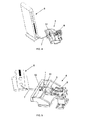
Fig. 2 is a perspective view of the dimensional control system for mechanically formed tubes made in accordance with a preferred embodiment of the present invention; -
Fig. 3 is a perspective view of a generic equipment of forming connecting tubes in which the system illustrated inFig. 2 is duly integrated to the production process. -
Fig. 4 is a perspective view of a system illustrated inFig. 2 duly connected to the measurement device; and -
Fig. 5 is an amplified detail of the interconnection between the system ofFig. 2 and the measurement device illustrated inFig. 4 , thus providing for a detailed visualization of a sensor responsible for emitting data from the readings performed. - The invention will be described in detail based on the attached drawings, to which reference numerals will be given to facilitate their comprehension.
- The dimensional control system of the present invention is intended to dimensionally evaluate a determined region of a mechanically formed tube. More specifically, said system carries out the measurement of connecting
tubes 1 defined by substantiallycylindrical bodies 2 provided with aflange region 3, as can be seen fromFig. 1 wherein the region to be measured will be theflange region 3 of theconnecting tube 1, which will correspond to the closing diameter of thebipartite cavity 5 since this element will aid in appropriately sealing a refrigeration system. - It is important to clarify that after the steps of producing the formed connecting
tube 1, measurement is carried out by said system that can be jointly or removably coupled to an M-forming machine as illustrated inFig.3 . - In the preferred embodiment of the invention illustrated in
Fig. 2 , it is possible to observe that saiddimensional control system 4 comprises abipartite cavity 5 preferably defined by a movingpart 51 and by afixed part 52, wherein said bipartite cavity 5 - specifically its moving part 51 - cooperating with anactuator 6 with actuation axis coincident with the displacement axis of said movingpart 51. It should be pointed out that the functioning system of theactuator 6 can be electronic, pneumatic, hydraulic, mechanical or driven by another system, and the movement of said moving part of thebipartite cavity 5 can be in horizontal, rotational or angulated direction without, however, departing from the presently claimed scope of protection. - The system of the present invention further comprises
sensors 7 cooperating with thebipartite cavity 5, and ameasurement device 8 cooperating withsaid sensors 7. - It is worth to mention that the formed connecting
tube 1 is transferred to the inside of thebipartite cavity 5 using a system of claws or other similar means such that same is positioned with theflange region 3 coincident with the inner diameter of saidbipartite cavity 5. When being positioned, theactuator 6 is driven which causes thebipartite cavity 5 to close. - After closing, said
sensor 7, or potentiometric rule, or also potentiometric pen, which can be disposed at any place that permits to read the closing diameter of thebipartite cavity 5, sends the read data to ameasurement device 8 that in the preferred embodiment of the invention is a measurement column programmed with variation limits acceptable forflange region 3. In the case that the measurement detects that the diameter offlange 3 of the connectingtube 1 is not within the accepted limits, an electronic, visual and/or sonorous signal will be emitted, and the connectingtube 1 will be automatically segregated from the other produced parts. Thus, in a totally computerized mode and without requiring an operator, only those tubes whose dimensional features are accepted to impart good sealing conditions and performance to hermetic compressors are sent to the next production step. - In this sense, it is worth to mention that the mode of segregating the equipment can be defined by several manners such as, for example, simply releasing the tube to the lower surface of the system so that same is directed to a collecting container, or by a specific plan designed to the system of claws.
- Hence, in addition to being conducted in a totally computerized way, a dimensional control of the
flange region 3, the discloseddimensional control system 4 further comprises means to determine the discharge of connectingtubes 1 produced with incompatibly acceptable dimensional parameters, that is, not within the predetermined dimensions. - The dimensional control method for connecting
tubes 1, in accordance with the present invention, comprises, therefore, the following steps of: - transferring the connecting
tube 1 to adimensional control system 4 by means of a system of claws or other similar device; - coupling said connecting
tube 1 to abipartite cavity 5 defined by the at least one movingpart 51, wherein saidbipartite cavity 5 is cooperating with theflange region 3 of the connectingtube 1; - driving an
actuator 6 cooperating with the at least one movingpart 51 of the at least onebipartite cavity 5 until same closes; - reading by means of at least one
sensor 7 data relative to the diameter resulting from the closing of thebipartite cavity 5; - receiving, by means of a
measurement device 8, data emitted by saidsensor 7; - comparing, by means of a
measurement device 8, data emitted by saidsensor 7 to the data of the acceptable variation limits programmed in saidmeasurement device 8 for thetube connecting tube 1; - in the case that the measurement detects that the diameter of
flange 3 of the connectingtube 1 does not fall within the accepted limits, an electronic, visual and/or sonorous signal will be emitted and then theactuator 6 cooperating with said at least one movingpart 51 of the at least onebipartite cavity 5 is driven until same opens such that the other cylinder acts to remove the connectingtube 1 which does not meet the required standards, preferably said connectingtube 1 falls over mat E and the other actuator displaces the flawed tube to a discharge compartment. - in the case that the measurement result is within the accepted dimensional limits, the
actuator 6 cooperating with said at least one moving part of said at least one bipartite cavity is driven until same opens and the connectingtube 1 falls over a met to be transported to the next step of the production process or into a storage and transport container, as necessary. - returning the system to the initial position to eventually start a new measurement procedure.
- It should be emphasized that although the preferred embodiments of the present invention have been shown, it is understood that eventual omissions, substitutions, electric pole inversion, and construction modifications can be made by a person skilled in the art without departing from the spirit and claimed scope of protection. It is also expressly predicted that all combinations of elements that perform the same function substantially in the same form to achieve the same results are within the scope of the invention. Substitution of elements of a described embodiment by others are also fully intended and contemplated.
- However, attention should be drawn to the fact that the given description based on the figures above only refers to some possible embodiments for the system of the present invention, wherein the real scope is, therefore, provided by the appended claims.
Claims (3)
- Dimensional control system for connecting tubes, wherein said connecting tubes 1 are defined by substantially cylindrical bodies 2 provided with a flange region 3, CHARACTERIZED in that said dimensional control system comprises:- at least one bipartite cavity 5 defined by at least one moving part 51, said bipartite cavity 5 cooperating with the connecting tube, wherein the inner diameter of the bipartite cavity 5 corresponds to the outer diameter of the flange region 3 of the connecting tube;- at least one actuator 6 cooperating with at least one moving part 51 of said at least one bipartite cavity 5;- at least one sensor cooperating with said at least one bipartite cavity; and- at least one measuring device 8 cooperating with said at least one sensor 7;
wherein said dimensional control system 4 further comprises means to determine discharge of the connecting tubes 1 produced with the flange region 3 having its diameter outside the predetermined dimensions. - System, in accordance with claim 1, CHARACTERIZED in that said at least one moving part 51 cooperating with said at least one actuator 6 effects at least one of the following movements: horizontal, vertical and rotational.
- Dimensional control method for connecting tubes 1 defined by substantially cylindrical bodies 2 provided with a flange region 3, CHARACTERIZED in that said dimensional control method comprises the following steps of:- transferring the connecting tube 1 to a dimensional control system 4 by means of a system of claws or another similar device;- coupling the connecting tube 1 to a bipartite cavity 5 defined by at least one moving part 51.said bipartite cavity cooperating with the flange region 3 of said connecting tube 1;- driving an actuator 6 cooperating with said at least one moving part 51 of said at least one bipartite cavity 5 until same closes;- reading, by means of a sensor 7, data relative to the diameter resulting from the closing of said bipartite cavity 5;- receiving, by means of a measurement device 8, data emitted by said sensor 7;- comparing, by means of said measuring device 8, data emitted by the sensor 7 to data of the accepted variation limits programmed in the measurement device 8 for the connecting tube 1;- in the case that the measurement detects that the diameter of flange 3 of the connecting tube 1 does not fall within the accepted limits, an electronic, visual and/or sonorous signal will be emitted and then the actuator 6 cooperating with said at least one moving part 51 of the at least one bipartite cavity 5 is driven until same opens such that the other cylinder acts to remove a connecting tube 1 which does not meet the required standards; preferably said connecting tube 1 falls over a mat and the other actuator displaces the flawed tube to a discharge compartment.- in the case that the measurement result is within the accepted dimensional limits, the actuator 6 cooperating with said at least one moving part of said at least one bipartite cavity is driven until same opens and the connecting tube 1 falls over a mat to be transported to the next step of the production process or into a storage and transport container, as necessary.- returning the system to the initial position to eventually start a new measurement procedure.
Applications Claiming Priority (2)
| Application Number | Priority Date | Filing Date | Title |
|---|---|---|---|
| BRBR102012028900-8A BR102012028900A2 (en) | 2012-11-12 | 2012-11-12 | DIMENSIONAL CONTROL SYSTEM AND METHOD FOR CONNECTED PIPES |
| PCT/BR2013/000477 WO2014071487A1 (en) | 2012-11-12 | 2013-11-07 | System and method for dimensional control of connector tubes |
Publications (2)
| Publication Number | Publication Date |
|---|---|
| EP2813799A1 true EP2813799A1 (en) | 2014-12-17 |
| EP2813799A4 EP2813799A4 (en) | 2015-06-10 |
Family
ID=50683855
Family Applications (1)
| Application Number | Title | Priority Date | Filing Date |
|---|---|---|---|
| EP13853873.1A Withdrawn EP2813799A4 (en) | 2012-11-12 | 2013-11-07 | System and method for dimensional control of connector tubes |
Country Status (5)
| Country | Link |
|---|---|
| EP (1) | EP2813799A4 (en) |
| CN (1) | CN104024788A (en) |
| BR (1) | BR102012028900A2 (en) |
| MX (1) | MX2014008075A (en) |
| WO (1) | WO2014071487A1 (en) |
Family Cites Families (13)
| Publication number | Priority date | Publication date | Assignee | Title |
|---|---|---|---|---|
| US1623352A (en) * | 1921-05-09 | 1927-04-05 | Westinghouse Lamp Co | Automatic cut-tube-sorting machine |
| US2525050A (en) * | 1947-04-22 | 1950-10-10 | Gen Electric | Gauging apparatus for lengths of tubing or rod |
| CH647189A5 (en) * | 1982-06-03 | 1985-01-15 | Meseltron Sa | DEVICE FOR HANDLING A CYLINDRICAL OR SPHERICAL PART. |
| DE3816130A1 (en) * | 1988-05-11 | 1989-11-23 | Althaus P Gerhard Dr Ing | Device for measuring the length, the diameters, the wall thickness and the ovality of tubes (pipes), in particular of large tubes |
| DE4321261A1 (en) * | 1992-06-29 | 1994-02-24 | Strebel Engineering Kleindoett | Optical shape testing system e.g. for diameter of rotationally-symmetric screw - feeds separated components along inclined path to accelerate components under gravity and tests in free-flight path between flash lamp and high-resolution light-barrier-type camera |
| US20030079359A1 (en) * | 2001-10-30 | 2003-05-01 | Richards John E. | Tube diameter gage assembly |
| WO2005049244A2 (en) * | 2003-11-18 | 2005-06-02 | Control Gaging, Inc. | Pass-through gage and method of gaging a workpiece |
| CN2727694Y (en) * | 2004-08-29 | 2005-09-21 | 重庆宗申技术开发研究有限公司 | Piston pin detecting apparatus |
| CN200955948Y (en) * | 2006-08-04 | 2007-10-03 | 江浩 | Device for dynamically measuring geometrical size increase or decrease of object |
| CN101458075B (en) * | 2009-01-08 | 2011-05-04 | 哈尔滨工业大学 | Core rotor assembly dimension measuring device for turbo-charger |
| CN101934273A (en) * | 2010-09-29 | 2011-01-05 | 株洲硬质合金集团有限公司 | Method for automatically detecting, sorting and counting diameters of rods |
| CN202511779U (en) * | 2012-04-13 | 2012-10-31 | 河北新兴铸管有限公司 | Online automatic detection device for nodular cast iron pipe |
| CN102768021B (en) * | 2012-08-01 | 2014-11-26 | 安徽工业大学 | Contact-type cylinder diameter measurement device |
-
2012
- 2012-11-12 BR BRBR102012028900-8A patent/BR102012028900A2/en not_active IP Right Cessation
-
2013
- 2013-11-07 EP EP13853873.1A patent/EP2813799A4/en not_active Withdrawn
- 2013-11-07 WO PCT/BR2013/000477 patent/WO2014071487A1/en not_active Ceased
- 2013-11-07 MX MX2014008075A patent/MX2014008075A/en unknown
- 2013-11-07 CN CN201380004624.4A patent/CN104024788A/en active Pending
Also Published As
| Publication number | Publication date |
|---|---|
| CN104024788A (en) | 2014-09-03 |
| WO2014071487A1 (en) | 2014-05-15 |
| EP2813799A4 (en) | 2015-06-10 |
| BR102012028900A2 (en) | 2014-10-21 |
| MX2014008075A (en) | 2014-10-06 |
Similar Documents
| Publication | Publication Date | Title |
|---|---|---|
| US11887291B2 (en) | Systems and methods for inspecting pipelines using a robotic imaging system | |
| CN203385680U (en) | Inner wall surface defect image acquiring device | |
| CN103808734B (en) | Auto-parts fully-automated synthesis equipment | |
| SA516370892B1 (en) | Pipe joint structure, seal member, joining state management method for pipe joint, and joining state management device for pipe joint | |
| US9804102B2 (en) | Device for testing ducts | |
| CN105548775B (en) | A kind of outdoor machine of air-conditioner safety automatic checkout equipment and detection method | |
| US9016322B2 (en) | Device for renovating a pipe | |
| KR20170036488A (en) | Boiler tube diagnosis apparatus | |
| CN104613922B (en) | The measuring system and method for a kind of contour of object | |
| DE102012220513A1 (en) | Method and device for producing a die-cast part | |
| CN103424086A (en) | Image collection device for internal surface of long straight pipe | |
| CN107315083A (en) | The soil monitoring device worked repeatedly | |
| CN118130170A (en) | A robot and method for automatically detecting gas in transformer oil | |
| CN103567736B (en) | A kind of side window glass erecting device and installation method | |
| EP2813799A1 (en) | System and method for dimensional control of connector tubes | |
| JP6315605B2 (en) | Structure shooting system | |
| CN204495315U (en) | A kind of measuring system of contour of object | |
| US20260046504A1 (en) | Cleanliness inspection system for inspection of an inner space of mobile transport tanks | |
| US20230204346A1 (en) | Method ad Apparatus for Digital Thread Inspection | |
| CN111537439A (en) | System and method for automatically identifying and evaluating defects of pressure-bearing equipment | |
| CN208636219U (en) | A kind of full-automatic quality detecting system for fatigue test specimen | |
| CN117054253A (en) | Elastic retainer ring limit bending detection equipment and detection method | |
| EP3348827A1 (en) | Interior inspection of a wind turbine blade | |
| KR101947323B1 (en) | Method for detecting water level of heat transfer tubes and method for inspecting heat transfer tubes | |
| CN205484596U (en) | Outer machine ann rule automated inspection equipment of air conditioner |
Legal Events
| Date | Code | Title | Description |
|---|---|---|---|
| PUAI | Public reference made under article 153(3) epc to a published international application that has entered the european phase |
Free format text: ORIGINAL CODE: 0009012 |
|
| 17P | Request for examination filed |
Effective date: 20141029 |
|
| AK | Designated contracting states |
Kind code of ref document: A1 Designated state(s): AL AT BE BG CH CY CZ DE DK EE ES FI FR GB GR HR HU IE IS IT LI LT LU LV MC MK MT NL NO PL PT RO RS SE SI SK SM TR |
|
| AX | Request for extension of the european patent |
Extension state: BA ME |
|
| RA4 | Supplementary search report drawn up and despatched (corrected) |
Effective date: 20150512 |
|
| RIC1 | Information provided on ipc code assigned before grant |
Ipc: B07C 5/07 20060101ALI20150506BHEP Ipc: G01B 5/08 20060101AFI20150506BHEP Ipc: G01B 5/00 20060101ALI20150506BHEP Ipc: F25B 41/00 20060101ALI20150506BHEP |
|
| DAX | Request for extension of the european patent (deleted) | ||
| STAA | Information on the status of an ep patent application or granted ep patent |
Free format text: STATUS: THE APPLICATION IS DEEMED TO BE WITHDRAWN |
|
| 18D | Application deemed to be withdrawn |
Effective date: 20180602 |