EP2813643B1 - System zur steuerung der stabilität eines pumpwagens, steuerverfahren dafür und pumpwagen - Google Patents
System zur steuerung der stabilität eines pumpwagens, steuerverfahren dafür und pumpwagen Download PDFInfo
- Publication number
- EP2813643B1 EP2813643B1 EP12868115.2A EP12868115A EP2813643B1 EP 2813643 B1 EP2813643 B1 EP 2813643B1 EP 12868115 A EP12868115 A EP 12868115A EP 2813643 B1 EP2813643 B1 EP 2813643B1
- Authority
- EP
- European Patent Office
- Prior art keywords
- pump truck
- parameters
- stable area
- boom
- axis
- Prior art date
- Legal status (The legal status is an assumption and is not a legal conclusion. Google has not performed a legal analysis and makes no representation as to the accuracy of the status listed.)
- Not-in-force
Links
- 238000000034 method Methods 0.000 title claims description 37
- 230000005484 gravity Effects 0.000 claims description 143
- 238000005086 pumping Methods 0.000 claims description 71
- 238000010586 diagram Methods 0.000 description 11
- 238000006073 displacement reaction Methods 0.000 description 7
- 230000000694 effects Effects 0.000 description 5
- 238000010276 construction Methods 0.000 description 4
- 230000003068 static effect Effects 0.000 description 3
- 239000000463 material Substances 0.000 description 2
- 238000012986 modification Methods 0.000 description 2
- 230000004048 modification Effects 0.000 description 2
- 230000006978 adaptation Effects 0.000 description 1
- 238000013461 design Methods 0.000 description 1
- 238000012423 maintenance Methods 0.000 description 1
- 238000005259 measurement Methods 0.000 description 1
Images


Classifications
-
- B—PERFORMING OPERATIONS; TRANSPORTING
- B60—VEHICLES IN GENERAL
- B60P—VEHICLES ADAPTED FOR LOAD TRANSPORTATION OR TO TRANSPORT, TO CARRY, OR TO COMPRISE SPECIAL LOADS OR OBJECTS
- B60P1/00—Vehicles predominantly for transporting loads and modified to facilitate loading, consolidating the load, or unloading
-
- E—FIXED CONSTRUCTIONS
- E04—BUILDING
- E04G—SCAFFOLDING; FORMS; SHUTTERING; BUILDING IMPLEMENTS OR AIDS, OR THEIR USE; HANDLING BUILDING MATERIALS ON THE SITE; REPAIRING, BREAKING-UP OR OTHER WORK ON EXISTING BUILDINGS
- E04G21/00—Preparing, conveying, or working-up building materials or building elements in situ; Other devices or measures for constructional work
- E04G21/02—Conveying or working-up concrete or similar masses able to be heaped or cast
- E04G21/04—Devices for both conveying and distributing
- E04G21/0418—Devices for both conveying and distributing with distribution hose
- E04G21/0436—Devices for both conveying and distributing with distribution hose on a mobile support, e.g. truck
-
- E—FIXED CONSTRUCTIONS
- E04—BUILDING
- E04G—SCAFFOLDING; FORMS; SHUTTERING; BUILDING IMPLEMENTS OR AIDS, OR THEIR USE; HANDLING BUILDING MATERIALS ON THE SITE; REPAIRING, BREAKING-UP OR OTHER WORK ON EXISTING BUILDINGS
- E04G21/00—Preparing, conveying, or working-up building materials or building elements in situ; Other devices or measures for constructional work
- E04G21/02—Conveying or working-up concrete or similar masses able to be heaped or cast
- E04G21/04—Devices for both conveying and distributing
- E04G21/0418—Devices for both conveying and distributing with distribution hose
- E04G21/0445—Devices for both conveying and distributing with distribution hose with booms
- E04G21/0463—Devices for both conveying and distributing with distribution hose with booms with boom control mechanisms, e.g. to automate concrete distribution
-
- G—PHYSICS
- G05—CONTROLLING; REGULATING
- G05D—SYSTEMS FOR CONTROLLING OR REGULATING NON-ELECTRIC VARIABLES
- G05D15/00—Control of mechanical force or stress; Control of mechanical pressure
Definitions
- the present invention involves the technical field of concrete pump truck control, and particularly, relates to a pump truck stability control system.
- the present invention further provides a pump truck stability control method and a pump truck.
- a concrete pump truck is a typical pump truck, and to ensure safety during the construction of the concrete pump truck, a usual practice is to use a removable protruding landing leg so as to extend the length of a landing leg and then expand the support range of the concrete pump truck to reduce danger of rollover.
- external loads such as actions of a boom and pumping operation incur the vibration of the whole truck, and then result in offset of gravity centre, and also, the geographic factors of the operation environments of the concrete pump truck are complex, when an operator misestimates the state of the pump truck or misoperates the pump truck, rollover may be incurred.
- a typical stability control system in the prior art usually comprises a detecting device, a controlling device and an alarm device, and the detecting device is mainly used for detecting the current positions of the gravity centres of the parts of the concrete pump truck and transmitting gravity centre position signals to the controlling device, and the controlling device calculates a complete machine gravity centre according to a predetermined strategy and compares it with a preset balance range, when the complete machine gravity centre falls out of the balance range, the alarm device alarms.
- the detecting device in the prior art only takes into consideration several factors of turret dip angle, boom extension, the unfolding angle of the landing leg and the displacement of the landing leg to calculate the gravity centre of a concrete pump truck system and conduct anti-rollover analysis of the pump truck, as the factors as considered are few, the precision in calculating the gravity centre of the system is poor.
- the balance range in the prior art for judging the gravity centre position of the pump truck is set in advance and fixed, the error of judging is large.
- WO 2011/120396 discloses the preamble of claim 1 and claim 10.
- An object of the present invention is to provide a pump truck stability control system which has high precision in calculating gravity centre and improves safety during the operation of the pump truck.
- the other object of the present invention is provide a pump truck comprising the stability control system, and a pump truck stability control method.
- the present invention provides a pump truck stability control system according to claim 1, comprising a detecting device and a controlling device, the detecting device is used for obtaining pumping state parameters, boom posture parameters, landing leg posture parameters, pump truck body position state parameters and current numerical signals of external load parameters acting on a boom;
- the controlling device comprises a complete machine gravity centre calculating unit and a pump truck stability control unit;
- the complete machine gravity centre calculating unit is used for receiving the current numerical signals of the parameters detected by the detecting device, and first calculating the gravity center position of a boom system according to the pumping state parameters, the boom posture parameters and the external load parameters, calculating the gravity centre position of the body of the pump truck according to the landing leg posture parameters and the pump truck body position state parameters, and then calculating the complete machine gravity centre position of the concrete pump truck according to the gravity centre position of the boom system and the gravity centre position of the body of the pump truck; and the pump truck stability control unit conducts stability control over the pump truck according to the position of the complete machine gravity centre in a pump truck stable area
- the pump truck stable area comprises a first stable area, the positions of the support points of the landing legs are determined according to the landing leg posture parameters, and a first polygon boundary formed by sequentially connecting the support points of the landing legs is the boundary of the first stable area; a second stable area is provided within the boundary of the first stable area, and a second polygon boundary determined according to the first stable area and preset safe operation parameters is the boundary of the second stable area.
- the controlling device further comprises an area adjusting unit which adjusts the boundary of the second stable area in combination with the pumping state parameters.
- the controlling device further comprises a stability alarm unit
- the pumping truck stability control unit When the complete machine gravity center position is out of the second stable area, the pumping truck stability control unit sends a first stability alarm signal, and the stability alarm unit conducts a first stability alarm prompt; or, when the complete machine gravity center position is within the second stable area and the minimum distance between the complete machine gravity center and the boundary of the second stable area is smaller than or equal to a predetermined safe distance, the pump truck stability control unit sends a second stability alarm signal, and the stability alarm unit conducts a second stability alarm prompt.
- the controlling device further comprises a state locking unit
- the state locking unit sends a state lock control signal, and the pumping state controlling device and/or boom posture controlling device of the pump truck locks the current pumping state parameters and/or the boom posture parameters of the pump truck according to the state lock signal.
- the controlling device further comprises a self-adaptation adjusting unit
- the self-adaptation adjusting unit sends a self-adaptation adjustment signal, and the pumping state controlling device and/or boom posture controlling device of the pump truck adjusts the current pumping state parameters and/or the boom posture parameters of the pump truck according to the self-adaptation adjustment signal so that the complete machine gravity center is within the second stable area.
- the detecting device comprises a detecting unit for detecting the external load on the boom system, which is provided on the boom of the pump truck.
- the stability control system in the present invention takes into consideration not only the factor parameters of the concrete pump truck such as the pumping state parameters, the zoom posture parameters, the landing leg posture parameters and the pump truck body position state parameters, but also external load factors and external load parameters, that is, the influence of external factors on the stability of the concrete pump truck, and the considered factors are comprehensive, and the present invention also provides a precise method for calculating the complete machine gravity center position, improves the precision of the stability control system in calculating the gravity center, enhances the accuracy of control, and improves the safety of the concrete pump truck during construction.
- the present invention also provides a pump truck comprising any of the above pump truck stability control systems, as the concrete pump truck comprises the stability control system comprising the above technical effect, the concrete pump truck comprises the technical effect of the above stability control systems.
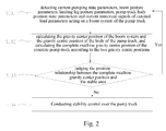
- the present invention also provides a pump truck stability control method according to claim 10, which is carried out according to following steps:
- step S103 is specifically as follow:
- step S103 is specifically as follow:
- step S103 is specifically as follow:
- a pump truck stability control method provided by the present invention is executed by the above pump truck stability control system, and thus also comprises the technical effect of the above pump truck stability control system.
- the core of the present invention is to provide a pump truck stability control system, which achieves high precision in the calculation of gravity center and improves the safety during the operation of the pump truck.
- the other core of the present invention is to provide a pump truck comprising the stability control system, and a pump truck stability control method.
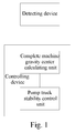
- FIG. 1 it is a block diagram of the constitution of the first embodiment of the concrete pump truck stability control system provided by the present invention.
- the present invention provides a pump truck stability control system comprising a detecting device and controlling device.
- the detecting device is used for detecting current pumping state parameters, boom posture parameters, landing leg posture parameters, pump truck body position state parameters and external load parameters acting on a pump truck boom system
- the pumping state parameters mainly refer to working state parameters of a pumping operation, such as the pressure of the hydraulic system of a pumping mechanism, the opening of an oil pump, the motion stroke of a piston, the motion speed of the piston, reversing pressure, the number of reversings and internal pressure of a master cylinder
- the boom posture parameters mainly refer to the parameters of the working positions of the booms of the boom system, such as unfolding angles and unfolding directions of the booms
- the landing leg posture parameters mainly comprise the angles between the landing legs during operation, the extension lengths of the landing legs and etc.
- the pump truck body position state parameters comprises the position parameters of the pump truck body and a predetermined plane, for example, the parameter of the angle between the pump truck body and the horizontal plane; the above parameters may refer to relevant technical materials in the prior art, which are omitted here
- the pump truck body position state parameters can be obtained through a dip angle sensor 1 mounted on the chassis body of the pump truck
- the boom posture parameters can be obtained through boom angle sensors 3 provided on respective booms for detecting the unfolding angles of the booms
- the landing leg posture parameters can be obtained through landing leg angle sensors 4 and landing leg displacement sensors 5 provided on the landing legs
- the landing leg displacement sensors 4 detect the flex displacement of a flexing landing leg
- the landing leg angle sensors 5 are used for detecting the swing angle of a swinging landing leg.
- the external load parameters mainly comprise the force applied by external environments on the concrete pump truck (for example, the influence of wind, rain and etc. on the concrete pump truck), as the influence of the external environments on the pump truck body is small, the present invention takes into consideration influence factors of external environments on the boom system.
- an external load parameter detecting part can be mounted on each boom of the boom system, or is mounted at a suitable position of a proper boom, for example, in Fig. 6 the external load parameter detecting part can be provided on the third boom.
- a wind speed sensor can be mounted on the boom system, and wind speed grades can be obtained through the wind speed sensor and is then converted into wind force, i.e., the size of external load applied by the wind on the boom.
- the controlling device comprises a complete machine gravity centre calculating unit and a pump truck stability control unit; the complete machine gravity centre calculating unit is used for receiving the parameters detected by the detecting device, and first calculating the gravity center position of a boom system according to the pumping state parameters, the boom posture parameters and the external load parameters, calculating the gravity centre position of the body of the pump truck according to the landing leg posture parameters and the pump truck body position state parameters, and then calculating the complete machine gravity centre position of the concrete pump truck according to the gravity centre position of the boom system and the gravity centre position of the body of the pump truck.
- the calculating methods in this unit can comprise a finite element method, a force system balancing method, a torque balancing method and etc., and such methods have strong adaptation and help achieve computer programming.
- the static gravity center position of the overall boom system is calculated according to the static gravity center position of a single boom in combination with the posture of the boom, then pumping state parameters (when the gravity center position of the boom system is calculated, at this moment the pumping state parameters can be pumping reversing impact parameters) and the influence of the external loads are integrated, and pumping reversing impact and external loads are integrated in the form of acting forces into the torque of the static gravity center of the boom system; in an established optimal coordinate system, the system is subjected to a force analysis through a force system balancing method and a torque balancing method, then actual gravity centre coordinates of the overall boom system are calculated through a torque balancing equation and a force system balancing equation.
- OG 2 x , OG 2 y and OG 2 z respectively represent the arms of force of the component forces of the gravity forces of the zoom connecting part and the conveying pipe at axis x, axis y and axis z; and K 1 , K 2 and K 3 respectively represent torque compensation values acting on axis x, axis y and axis z, and the torque compensation values are preset in consideration of the model of the pump truck, the length of the boom, current pumping displacement and current pumping state.
- the pump truck stability control unit in the controlling device is used for judging the position relationship between the complete machine gravity center and the pump truck stable area in the current state, and obtaining the judging result of the complete machine gravity center and the pump truck stable area in the current state, that is, whether the complete machine gravity center falls within or out of the pump truck stable area; the pump truck is subjected to stability control according to the judging result of the position relationship between the complete machine gravity center and the pump truck stable area in the current state, that is, sending a stability control signal.
- the stability control signal can be an alarm signal, an adjustment signal of a boom action and/or a pumping state, and a lock signal of the boom action and/or the pumping state;
- the alarm signal can remind an operator that the current state of the concrete pump truck is a dangerous working condition, so as to take corresponding measures to improve the current working condition of the concrete pump truck so that it is in a safe working condition, or a control signal is directly sent to an executing part of the concrete pump truck to automatically adjust the operation condition of the concrete pump truck, so that the complete machine gravity center is within the stable area to ensure the safe operation of the concrete pump truck, or a control signal is directly sent to the executing part of the concrete pump truck, and then the current operation condition of the concrete pump truck is locked automatically to avoid the rollover of the concrete pump truck.
- the stability control signal can also be the combination of the alarm signal and the adjustment signal, to adjust the working state of the concrete pump truck while remind a user of the current working state of the concrete pump truck, so that the complete machine gravity center moves towards the stable area; or, the stability control signal is the combination of the alarm signal and the lock signal, to lock the working state of the concrete pump truck while remind the user of the current working state of the concrete pump truck and then avoid the rollover of the concrete pump truck.
- the stability control system in the present invention takes into consideration not only the factor parameters of the concrete pump truck such as the pumping state parameters, the zoom posture parameters, the landing leg posture parameters and the pump truck body position state parameters, but also external load parameters, that is, the influence of external environment factors on the stability of the concrete pump truck, and the considered factors are comprehensive, and the present invention also provides a precise method for calculating the complete machine gravity center position, improves the precision of the stability control system in calculating the gravity center, enhances the accuracy of control, and improves the safety of the concrete pump truck during construction.
- Fig. 2 is a flow chart of the first embodiment of the pump truck stability control method provided by the present invention, and the control method comprises the following steps:
- the stable area can comprise a first stable area and a second stable area within the boundary of the first stable area, and the boundary of the first stable area can be determined by the support points of the landing legs determined according to the landing leg posture parameters, and a first polygon boundary formed by sequentially connecting the support points of the landing legs is the boundary of the first stable area; a second polygon boundary determined according to the first stable area and preset safe operation parameters is the boundary of the second stable area.
- a pump truck database can be established comprising pump truck model, boom length, pumping displacement, pumping master system working parameters and etc., and then preset safe operation parameters are determined according to the parameters; during specific implementation, the area ratio of the two polygons and/or the distance parameters of the sides of the two polygons can be determined according to the above parameters, for example, it is determined according to the above parameters that the area of the second polygon is 0.9 time of the area of the first polygon, and/or the distance parameters of the sides of the second polygon and the corresponding sides of the first polygon are determined.
- the stable area is divided into a first stable area and a second stable area, and more accurate control over the pump truck can be achieved and pump truck operation safety can be enhanced.
- the arrangement manner depends on the position relationship between the complete machine gravity center and the first stable area boundary and the second stable area boundary, different control solutions can be selected to achieve multi-layered control to further enhance control over the pump truck safety.
- the controlling device in the present invention can further comprise an area adjusting unit, and the area adjusting unit evaluates the stability safety of the pump truck according to the current operation parameters transmitted in real time by the detecting device and thus adjusts the boundary of the second stable area to meet needs of current pump truck operation parameters.
- the stability control system in the present invention can conduct real-time adjustment and planning to the second stable area to adapt to different working conditions of the concrete pump truck and further improve the accuracy of the control system in determining the stability of the concrete pump truck.
- control system can be further provided with a stability analyzing module which can comprise CSP (conservative support polygon) rule, ESM (energy stability margin) rule, CSSM (compliance stance stability margin) rule, ZMP (zero moment point) rule and force-angle stability measuring method and etc., to adapt to the anti-rollover measurement rule of a flexible multi-freedom concrete pump truck.
- a stability analyzing module which can comprise CSP (conservative support polygon) rule, ESM (energy stability margin) rule, CSSM (compliance stance stability margin) rule, ZMP (zero moment point) rule and force-angle stability measuring method and etc.
- Fig. 3 is a block diagram of the constitution of the second embodiment of the concrete pump truck stability control system provided by the present invention.
- the controlling device further comprises a stability alarm unit which is connected with the pump truck stability control unit.
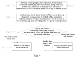
- the stability control signal sent by the pumping truck stability control unit is a first stability alarm signal, and the stability alarm unit conducts a first stability alarm prompt; or, when the complete machine gravity center position is within the second stable area and the minimum distance between the complete machine gravity center and the boundary of the second stable area is smaller than or equal to a predetermined safe distance, the pump truck stability control unit sends a second stability alarm signal, and the stability alarm unit conducts a second stability alarm prompt.
- This arrangement can improve operator's understanding of the operation condition of the concrete pump truck, and the control flexibility is high.
- Fig. 4 is a flow chart of the second embodiment of the pump truck stability control method provided by the present invention, and the control method comprises the following steps:
- the stable area can be divided into more grades of areas, and correspondingly more grades of alarm devices are provided, and the alarm devices can remind the operator in different forms of sound, light or the combination of the two, so that the operator can more conveniently get to know the operation condition of the concrete pump truck and then conduct maintenance timely.
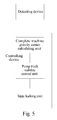
- Fig. 5 is a block diagram of the constitution of the third embodiment of the pump truck stability control system provided by the present invention.
- the controlling device further comprises a state locking unit connected with the pump truck stability control unit.
- the state locking unit sends a state lock control signal, and the pumping state controlling device and/or boom posture controlling device of the pump truck locks the current pumping state parameters and/or the boom posture parameters of the pump truck according to the state lock signal.
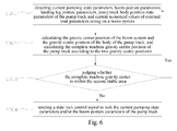
- Fig. 6 is a flow chart of the third embodiment of the pump truck stability control method provided by the present invention, and the control method comprises following steps:
- the pumping state parameters and/or boom posture parameters can be locked in a locking way to avoid further motion of the complete machine gravity center of the pump truck towards the boundary of the first stable area, thereby lowering the risk of the rollover of the pump truck.
- Fig. 7 is a block diagram of the constitution of the fourth embodiment of the concrete pump truck stability control system provided by the present invention.
- the controlling device can further comprise a self-adaptation adjusting unit connected with the pump truck stability control unit.
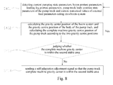
- the self-adaptation adjusting unit sends a self-adaptation adjustment signal, and the pumping state controlling device and/or boom posture controlling device of the pump truck adjusts the current pumping state parameters and/or the boom posture parameters of the pump truck according to the self-adaptation adjustment signal so that the complete machine gravity center is within the second stable area.
- the controlling device in the present invention can use advanced control theories such as self-adaptation control and robust control, and automatically adjusts parameters such as the current of a multi-way valve and pumping state according to changes of the gravity center, that is, gravity center track, boom posture and pumping impact are used as input of a controller, and the gravity center position is adjusted in real time for gravity center offset within a certain range in combination with external loads, pumping truck displacement and boom action which are deemed as interference factors to the system, and then it is ensured that the gravity center position is within the second stable area.
- advanced control theories such as self-adaptation control and robust control
- the stability control system in the present invention can adjust the pumping state parameters and/or the boom posture parameters of the concrete pump truck so that the gravity center of the concrete pump truck falls within the second stable area to enhance stability.
- Fig. 8 is a flow chart of the fourth embodiment of the pump truck stability control method provided by the present invention, and the specific control steps are as follow:
- Fig. 9 is a schematic diagram of the final assembly of the concrete pump truck provided by the present invention
- Fig. 10 is a top view of the concrete pump truck shown in Fig. 9 .
- the present invention further provides a concrete pump truck, and the stability control system is the pump truck stability control system described in the above embodiments.
- the concrete pump truck comprising the stability control system also comprises the technical effects.
Landscapes
- Engineering & Computer Science (AREA)
- Architecture (AREA)
- Mechanical Engineering (AREA)
- Civil Engineering (AREA)
- Structural Engineering (AREA)
- Physics & Mathematics (AREA)
- General Physics & Mathematics (AREA)
- Automation & Control Theory (AREA)
- Transportation (AREA)
- On-Site Construction Work That Accompanies The Preparation And Application Of Concrete (AREA)
- Jib Cranes (AREA)
Claims (14)
- Pumpfahrzeugstabilitätssteuerungssystem mit einer Erfassungseinrichtung und einer Steuereinrichtung,
dadurch gekennzeichnet, dass
die Erfassungseinrichtung zum Erfassen aktueller Pumpzustandparameter, Auslegerpositionsparameter, Abstützarmpositionsparameter, Pumpfahrzeugkarosseriepositionszustandparameter eines Pumpfahrzeugs und auf ein Pumpfahrzeugauslegersystem einwirkender äußerer Lastparameter verwendet wird;
die Steuereinrichtung eine Einheit zum Berechnen des Schwerpunkts der gesamten Maschine und eine Pumpfahrzeugstabilitätssteuerungseinheit aufweist;
die Einheit zum Berechnen des Schwerpunkts der gesamten Maschine dazu verwendet wird, die durch die Erfassungseinrichtung erfassten Parameter zu empfangen, wobei die Schwerpunktposition des Auslegersystems gemäß den Pumpzustandparametern, den Auslegerpositionsparametern und den externen Lastparametern berechnet wird, die Schwerpunktposition der Karosserie des Pumpfahrzeugs gemäß den Abstützarmpositionsparametern und den Pumpfahrzeugkarosseriepositionszustandparametern berechnet wird, und dann die Schwerpunktposition der gesamten Maschine des Pumpenfahrzeugs gemäß der Schwerpunktposition des Auslegersystems und der Schwerpunktposition der Karosserie des Pumpfahrzeugs berechnet wird; und
die Pumpfahrzeugstabilitätssteuerungseinheit eine Stabilitätssteuerung für das Pumpfahrzeug gemäß der Position des Schwerpunkts der gesamten Maschine in einem stabilen Pumpfahrzeugbereich ausführt. - System nach Anspruch 1,
dadurch gekennzeichnet, dass
der stabile Pumpfahrzeugbereich einen ersten stabilen Bereich aufweist, wobei die Positionen der Abstützpunkte der Abstützarme gemäß den Abstützarmpositionsparametern bestimmt werden und eine erste Polygongrenze, die durch sequentielles Verbinden der Abstützpunkte der Abstützarme gebildet wird, die Grenze des ersten stabilen Bereichs darstellt;
ein zweiter stabiler Bereich innerhalb der Grenze des ersten stabilen Bereichs bereitgestellt wird, wobei eine zweite Polygongrenze, die gemäß dem ersten stabilen Bereich und voreingestellten sicheren Betriebsparametern bestimmt ist, die Grenze des zweiten stabilen Bereichs darstellt. - System nach Anspruch 2, dadurch gekennzeichnet, dass die Steuereinrichtung ferner eine Bereicheinstelleinheit aufweist, die die Grenze des zweiten stabilen Bereichs in Kombination mit den Pumpzustandparametern einstellt.
- System nach Anspruch 2 oder 3,
dadurch gekennzeichnet, dass
die Steuereinheit ferner eine Stabilitätswarneinheit aufweist, wobei,
wenn die Schwerpunktposition der gesamten Maschine sich außerhalb des zweiten stabilen Bereichs befindet, die Pumpfahrzeugstabilitätssteuerungseinheit ein erstes Stabilitätswarnsignal ausgibt und die Stabilitätswarneinheit eine erste Stabilitätswarnmeldung anzeigt; oder
wenn die Schwerpunktposition der gesamten Maschine sich innerhalb des zweiten stabilen Bereichs befindet und der minimale Abstand zwischen dem Schwerpunkt der gesamten Maschine und der Grenze des zweiten stabilen Bereichs kleiner oder gleich einem voreingestellten sicheren Abstand ist, die Pumpfahrzeugstabilitätssteuerungseinheit ein zweites Stabilitätswarnsignal ausgibt und die Stabilitätswarneinheit eine zweite Stabilitätswarnmeldung anzeigt. - System nach Anspruch 2 oder 3,
dadurch gekennzeichnet, dass
die Steuereinrichtung ferner eine Zustandblockiereinheit aufweist, wobei,
wenn der Schwerpunkt der gesamten Maschine sich außerhalb des zweiten stabilen Bereichs befindet, die Zustandblockiereinheit ein Zustandblockiersteuersignal ausgibt und die Pumpzustandsteuerungseinrichtung und/oder die Auslegerpositionssteuerungseinrichtung des Pumpfahrzeugs die aktuellen Pumpzustandparameter und/oder die Auslegerpositionsparameter des Pumpfahrzeugs gemäß dem Zustandblockiersteuersignal blockieren. - System nach Anspruch 2 oder 3,
dadurch gekennzeichnet, dass
die Steuereinrichtung ferner eine Selbstadaptions-Einstelleinheit aufweist, wobei, wenn der Schwerpunkt der gesamten Maschine sich außerhalb des zweiten stabilen Bereichs befindet, die Selbstadaptions-Einstelleinheit ein Selbstadaptions-Einstellsignal ausgibt und die Pumpzustandsteuerungseinrichtung und/oder die Auslegerpositionssteuerungseinrichtung des Pumpfahrzeugs die aktuellen Pumpzustandparameter und/oder Auslegerpositionsparameter des Pumpfahrzeugs gemäß dem Selbstadaptions-Einstellsignal derart einstellen, dass der Schwerpunkt der gesamten Maschine sich innerhalb des zweiten stabilen Bereichs befindet. - System nach Anspruch 1,
dadurch gekennzeichnet, dass die Erfassungseinrichtung eine auf dem Ausleger des Pumpfahrzeugs bereitgestellte Erfassungseinheit zum Erfassen der auf das Auslegersystem einwirkenden externen Last aufweist. - System nach Anspruch 1,
dadurch gekennzeichnet, dass die Schwerpunktposition des Auslegersystems gemäß den folgenden Formeln berechnet wird:

- Pumpfahrzeug, dadurch gekennzeichnet, dass das Pumpfahrzeug das Pumpfahrzeugstabilitätssteuerungssystem nach einem der Ansprüche 1 bis 8 aufweist.
- Pumpfahrzeugstabilitätssteuerungsverfahren, gekennzeichnet durch die folgenden Schritte:S101: Erfassen aktueller Pumpzustandparameter, Auslegerpositionsparameter, Abstützarmpositionsparameter, Pumpfahrzeugkarosseriepositionszustandparameter eines Pumpfahrzeugs und äußerer Lastparameter, die auf ein Auslegersystem des Pumpfahrzeugs einwirken;S102: Berechnen der Schwerpunktposition des Auslegersystems gemäß den Pumpzustandparametern, den Auslegerpositionsparametern und den äußeren Lastparametern, Berechnen der Schwerpunktposition der Karosserie des Pumpfahrzeugs gemäß den Abstützarmpositionsparametern und den Pumpfahrzeugkarosseriepositionszustandparametern, und anschließendes Berechnen der Schwerpunktposition der gesamten Maschine des Pumpfahrzeugs gemäß der Schwerpunktposition des Auslegersystems und der Schwerpunktposition der Karosserie des Pumpfahrzeugs; undS103: Ausführen einer Stabilitätssteuerung für das Pumpfahrzeug gemäß der Positionsbeziehung des Schwerpunkts der gesamten Maschine in einem stabilen Pumpfahrzeugbereich.
- Verfahren nach Anspruch 10, dadurch gekennzeichnet, dass der stabile Pumpfahrzeugbereich einen ersten stabilen Bereich aufweist, wobei die Positionen der Abstützpunkte der Abstützarme gemäß den Abstützarmpositionsparametern bestimmt werden und eine erste Polygongrenze, die durch sequentielles Verbinden der Abstützpunkte der Abstützarme gebildet wird, die Grenze des ersten stabilen Bereichs darstellt, und ein zweiter stabiler Bereich innerhalb der Grenze des ersten stabilen Bereichs bereitgestellt wird, wobei eine zweite Polygongrenze, die gemäß dem ersten stabilen Bereich und voreingestellten sicheren Betriebsparametern bestimmt ist, die Grenze des zweiten stabilen Bereichs darstellt.
- Verfahren nach Anspruch 11, dadurch gekennzeichnet, dass Schritt S103 insbesondere folgendermaßen ausgeführt wird:wenn die Schwerpunktposition der gesamten Maschine sich außerhalb des zweiten stabilen Bereichs befindet, ein erstes Stabilitätswarnsignal ausgegeben wird, um eine erste Stabilitätswarnmeldung anzuzeigen; oderwenn die Schwerpunktposition der gesamten Maschine sich innerhalb des zweiten stabilen Bereichs befindet und der minimale Abstand zwischen dem Schwerpunkt der gesamten Maschine und der Grenze des zweiten stabilen Bereichs kleiner oder gleich dem voreingestellten sicheren Abstand ist, ein zweites Stabilitätswarnsignal ausgegeben wird, um eine zweite Stabilitätswarnmeldung anzuzeigen.
- Verfahren nach Anspruch 11, dadurch gekennzeichnet, dass Schritt S103 insbesondere folgendermaßen ausgeführt wird:wenn der Schwerpunkt der gesamten Maschine sich außerhalb des zweiten stabilen Bereichs befindet, ein Zustandblockiersteuersignal ausgegeben wird und die Pumpzustandsteuerungseinrichtung und/oder die Auslegerpositionssteuerungseinrichtung des Pumpfahrzeugs die aktuellen Pumpzustandparameter und/oder die Auslegerpositionsparameter des Pumpfahrzeugs gemäß dem Zustandblockiersteuersignal blockieren.
- Verfahren nach Anspruch 11, dadurch gekennzeichnet, dass Schritt S103 insbesondere folgendermaßen ausgeführt wird:wenn der Schwerpunkt der gesamten Maschine sich außerhalb des zweiten stabilen Bereichs befindet, ein Selbstadaptions-Einstellsignal ausgegeben wird und die Pumpzustandsteuerungseinrichtung und/oder die Auslegerpositionssteuerungseinrichtung des Pumpfahrzeugs die aktuellen Pumpzustandparameter und/oder Auslegerpositionsparameter des Pumpfahrzeugs gemäß dem Selbstadaptions-Einstellsignal derart einstellen, dass der Schwerpunkt der gesamten Maschine sich innerhalb des zweiten stabilen Bereichs befindet.
Applications Claiming Priority (2)
| Application Number | Priority Date | Filing Date | Title |
|---|---|---|---|
| CN201210025292.5A CN102588505B (zh) | 2012-02-06 | 2012-02-06 | 泵车稳定性控制系统、控制方法及泵车 |
| PCT/CN2012/074038 WO2013117046A1 (zh) | 2012-02-06 | 2012-04-14 | 泵车稳定性控制系统、控制方法及泵车 |
Publications (3)
| Publication Number | Publication Date |
|---|---|
| EP2813643A1 EP2813643A1 (de) | 2014-12-17 |
| EP2813643A4 EP2813643A4 (de) | 2015-08-26 |
| EP2813643B1 true EP2813643B1 (de) | 2016-08-17 |
Family
ID=46477592
Family Applications (1)
| Application Number | Title | Priority Date | Filing Date |
|---|---|---|---|
| EP12868115.2A Not-in-force EP2813643B1 (de) | 2012-02-06 | 2012-04-14 | System zur steuerung der stabilität eines pumpwagens, steuerverfahren dafür und pumpwagen |
Country Status (4)
| Country | Link |
|---|---|
| US (1) | US9381844B2 (de) |
| EP (1) | EP2813643B1 (de) |
| CN (1) | CN102588505B (de) |
| WO (1) | WO2013117046A1 (de) |
Cited By (3)
| Publication number | Priority date | Publication date | Assignee | Title |
|---|---|---|---|---|
| EP3705662A1 (de) | 2019-03-07 | 2020-09-09 | Liebherr-Mischtechnik GmbH | Gelenkarm-steuerung einer betonpumpe |
| EP3705664A1 (de) | 2019-03-07 | 2020-09-09 | Liebherr-Mischtechnik GmbH | Gelenkarm-steuerung einer betonpumpe |
| EP3705663A1 (de) | 2019-03-07 | 2020-09-09 | Liebherr-Mischtechnik GmbH | Gelenkarm-steuerung einer betonpumpe |
Families Citing this family (26)
| Publication number | Priority date | Publication date | Assignee | Title |
|---|---|---|---|---|
| CN102518305B (zh) * | 2011-12-13 | 2013-08-28 | 中联重科股份有限公司 | 混凝土泵车的臂架及混凝土泵车 |
| CN102514550B (zh) * | 2011-12-20 | 2014-04-30 | 长沙中联消防机械有限公司 | 工程机械以及其安全状态确定方法、装置和系统 |
| CN102774757B (zh) * | 2012-08-07 | 2015-05-06 | 三一汽车制造有限公司 | 工程机械 |
| CN102841566B (zh) * | 2012-09-18 | 2014-07-09 | 中联重科股份有限公司 | 混凝土泵车监控方法、混凝土泵车监控系统及混凝土泵车 |
| CN103345819B (zh) * | 2013-07-16 | 2015-07-15 | 中联重科股份有限公司 | 车辆倾翻预警系统、预警方法及包含该系统的工程机械 |
| CN103526939B (zh) * | 2013-10-31 | 2015-09-09 | 北汽福田汽车股份有限公司 | 一种车载式混凝土泵车 |
| DE102014215019A1 (de) | 2014-07-30 | 2016-02-04 | Putzmeister Engineering Gmbh | Autobetonpumpe und Verfahren zu deren Arbeitsbetrieb |
| CN105569338A (zh) * | 2015-12-31 | 2016-05-11 | 三一汽车制造有限公司 | 一种混凝土泵车排量提示系统和混凝土泵车 |
| CN106368435B (zh) * | 2016-09-28 | 2018-10-26 | 中国十七冶集团有限公司 | 一种框架剪力墙结构混凝土浇筑下料控制方法 |
| DE102016125450B4 (de) * | 2016-12-22 | 2025-12-31 | Schwing Gmbh | Fahrbarer Großmanipulator |
| CN107023537B (zh) * | 2017-03-27 | 2018-08-31 | 北京交通大学 | 液压系统的载荷均衡控制方法及系统 |
| DE102018104041A1 (de) * | 2018-02-22 | 2019-08-22 | Liebherr-Werk Nenzing Gmbh | Vorrichtung zur Veränderung der Bodendruckverteilung einer Arbeitsmaschine und entsprechende Arbeitsmaschine |
| US11131083B2 (en) * | 2019-10-31 | 2021-09-28 | Deere & Company | Vehicle stability warning system |
| FR3102785B1 (fr) | 2019-11-04 | 2021-10-08 | Quali Parts & Services | Pompe à béton équipée de moyens de détection de dangers |
| CN111395767A (zh) * | 2020-03-23 | 2020-07-10 | 湖南机电职业技术学院 | 一种臂架泵车防倾翻保护系统 |
| CN111608392B (zh) * | 2020-05-08 | 2022-04-12 | 中联重科股份有限公司 | 用于混凝土设备的防倾翻控制方法和系统、混凝土设备 |
| CN112049427A (zh) * | 2020-08-31 | 2020-12-08 | 三一汽车制造有限公司 | 臂架控制系统、方法和作业车辆 |
| CN112441511B (zh) * | 2020-11-17 | 2021-08-24 | 中联重科股份有限公司 | 工程机械及其支撑控制方法、装置、系统及介质 |
| CN112723201B (zh) * | 2021-01-08 | 2022-03-04 | 中联重科股份有限公司 | 获取支撑位置的方法、装置及工程机械、可读存储介质 |
| DE102021107140A1 (de) * | 2021-03-23 | 2022-09-29 | Putzmeister Engineering Gmbh | Ausfallsichere Standsicherheitsüberwachung für ein Dickstofffördersystem |
| DE102021207092A1 (de) * | 2021-07-06 | 2023-01-12 | Putzmeister Engineering Gmbh | Verfahren zum automatischen Einstellen einer veränderbaren Maststellung eines verstellbaren Verteilermasts einer Bau- und/oder Dickstoffpumpenvorrichtung und System |
| CN116065827A (zh) * | 2021-11-01 | 2023-05-05 | 河北雷萨重型工程机械有限责任公司 | 泵车布料的控制方法、装置、电子设备和泵车 |
| CN114421853B (zh) * | 2022-02-10 | 2023-11-03 | 三一汽车制造有限公司 | 电流控制方法、电流控制系统、臂架控制系统和车辆 |
| CN114753640B (zh) * | 2022-04-01 | 2023-04-07 | 中联重科股份有限公司 | 臂架末端运动规划方法、装置、控制系统及工程机械 |
| CN114772466A (zh) * | 2022-04-12 | 2022-07-22 | 浙江三一装备有限公司 | 起重机稳定性分析方法、起重机防倾覆控制方法及装置 |
| CN115771775A (zh) * | 2022-12-02 | 2023-03-10 | 中交一航局安装工程有限公司 | 一种斗轮悬臂式取料机调整上部结构平衡的方法 |
Family Cites Families (7)
| Publication number | Priority date | Publication date | Assignee | Title |
|---|---|---|---|---|
| JP3868161B2 (ja) * | 1999-09-17 | 2007-01-17 | 極東開発工業株式会社 | ラジコン通信機及びコンクリートポンプ車の遠隔操作パターン変更方法 |
| US6755212B1 (en) * | 2001-02-23 | 2004-06-29 | Schwing America, Inc. | Boom stiffening system |
| JP4045345B2 (ja) * | 2003-08-22 | 2008-02-13 | 飛島建設株式会社 | ポンプ脈動連動急結剤供給システム |
| CN102147959B (zh) * | 2010-02-08 | 2013-01-02 | 徐工集团工程机械股份有限公司建设机械分公司 | 一种倾翻报警系统及包括该系统的混凝土泵车 |
| CN101833287B (zh) * | 2010-03-30 | 2012-02-22 | 三一重工股份有限公司 | 工程机械及其稳定性控制系统 |
| CN101967883B (zh) * | 2010-09-09 | 2012-02-22 | 安徽星马汽车股份有限公司 | 一种泵车防倾翻控制电路 |
| CN102330498B (zh) * | 2011-07-14 | 2012-10-17 | 中联重科股份有限公司 | 泵车及其控制方法和装置 |
-
2012
- 2012-02-06 CN CN201210025292.5A patent/CN102588505B/zh active Active
- 2012-04-14 EP EP12868115.2A patent/EP2813643B1/de not_active Not-in-force
- 2012-04-14 WO PCT/CN2012/074038 patent/WO2013117046A1/zh not_active Ceased
- 2012-04-14 US US14/376,746 patent/US9381844B2/en not_active Expired - Fee Related
Cited By (6)
| Publication number | Priority date | Publication date | Assignee | Title |
|---|---|---|---|---|
| EP3705662A1 (de) | 2019-03-07 | 2020-09-09 | Liebherr-Mischtechnik GmbH | Gelenkarm-steuerung einer betonpumpe |
| EP3705664A1 (de) | 2019-03-07 | 2020-09-09 | Liebherr-Mischtechnik GmbH | Gelenkarm-steuerung einer betonpumpe |
| EP3705663A1 (de) | 2019-03-07 | 2020-09-09 | Liebherr-Mischtechnik GmbH | Gelenkarm-steuerung einer betonpumpe |
| DE102019105814A1 (de) * | 2019-03-07 | 2020-09-10 | Liebherr-Mischtechnik Gmbh | Gelenkarm-Steuerung einer Betonpumpe |
| DE102019105871A1 (de) * | 2019-03-07 | 2020-09-10 | Liebherr-Mischtechnik Gmbh | Gelenkarm-Steuerung einer Betonpumpe |
| DE102019105817A1 (de) * | 2019-03-07 | 2020-09-10 | Liebherr-Mischtechnik Gmbh | Gelenkarm-Steuerung einer Betonpumpe |
Also Published As
| Publication number | Publication date |
|---|---|
| EP2813643A4 (de) | 2015-08-26 |
| US20150112555A1 (en) | 2015-04-23 |
| WO2013117046A1 (zh) | 2013-08-15 |
| CN102588505A (zh) | 2012-07-18 |
| EP2813643A1 (de) | 2014-12-17 |
| US9381844B2 (en) | 2016-07-05 |
| CN102588505B (zh) | 2014-01-15 |
Similar Documents
| Publication | Publication Date | Title |
|---|---|---|
| EP2813643B1 (de) | System zur steuerung der stabilität eines pumpwagens, steuerverfahren dafür und pumpwagen | |
| EP2733281B1 (de) | Mischfahrzeug sowie steuerverfahren und -vorrichtung dafür | |
| CN101833287B (zh) | 工程机械及其稳定性控制系统 | |
| US8620534B2 (en) | Mobile working machine with a control device, comprising a working arm and methods for controlling the operating point of a working arm of a mobile working machine | |
| CN107215792B (zh) | 群塔防撞控制方法、控制装置 | |
| CN102915045B (zh) | 一种臂架类工程车辆的控制方法及装置 | |
| CN109179228B (zh) | 一种建筑施工塔吊机防碰系统 | |
| CN201619959U (zh) | 工程机械及其稳定性控制系统 | |
| EP2377653A1 (de) | Verfahren und system zur steuerung eines grossen verarbeitungsmanipulators | |
| CN102530786B (zh) | 作业平台自动调平控制方法、控制装置及控制系统 | |
| EP4411077A1 (de) | Herstellungsverfahren für ein elektronisches gehäuse für einen bagger | |
| JP2013204260A (ja) | 車両の遠隔操作装置、車両及び車両の遠隔操作方法 | |
| CN109264644A (zh) | 高空作业平台的调平控制系统、调平控制方法及高空作业平台 | |
| Jin et al. | Exploring the impact of wind loads on tower crane operation | |
| CN119612367A (zh) | 基于多传感器融合的智能塔式起重机防碰撞精准吊运系统 | |
| CN103604408A (zh) | 臂架工作状态参数检测方法、设备、系统及工程机械 | |
| JP6949727B2 (ja) | 作業機械の較正方法、較正装置および作業機械の較正システム | |
| CN115784023A (zh) | 用于工程设备的控制方法、处理器、控制装置及工程设备 | |
| CN106744325A (zh) | 一种测量与预报起重机臂架头部侧移的方法和装置 | |
| CN103676973B (zh) | 一种作业平台调平控制设备、方法、系统以及高空作业车 | |
| CN113233333B (zh) | 塔机及其工作参数检测方法和存储介质 | |
| CN103569867B (zh) | 一种起重机械臂架侧倾监控设备、系统、方法和工程机械 | |
| CN209668721U (zh) | 高空作业平台 | |
| US12094341B2 (en) | Risk management system | |
| CN102431912B (zh) | 一种塔机配重重量评估方法 |
Legal Events
| Date | Code | Title | Description |
|---|---|---|---|
| PUAI | Public reference made under article 153(3) epc to a published international application that has entered the european phase |
Free format text: ORIGINAL CODE: 0009012 |
|
| 17P | Request for examination filed |
Effective date: 20140826 |
|
| AK | Designated contracting states |
Kind code of ref document: A1 Designated state(s): AL AT BE BG CH CY CZ DE DK EE ES FI FR GB GR HR HU IE IS IT LI LT LU LV MC MK MT NL NO PL PT RO RS SE SI SK SM TR |
|
| AX | Request for extension of the european patent |
Extension state: BA ME |
|
| DAX | Request for extension of the european patent (deleted) | ||
| RA4 | Supplementary search report drawn up and despatched (corrected) |
Effective date: 20150728 |
|
| RIC1 | Information provided on ipc code assigned before grant |
Ipc: E04G 21/02 20060101AFI20150722BHEP Ipc: F16F 15/02 20060101ALI20150722BHEP Ipc: E04G 21/04 20060101ALI20150722BHEP |
|
| GRAP | Despatch of communication of intention to grant a patent |
Free format text: ORIGINAL CODE: EPIDOSNIGR1 |
|
| INTG | Intention to grant announced |
Effective date: 20160223 |
|
| GRAS | Grant fee paid |
Free format text: ORIGINAL CODE: EPIDOSNIGR3 |
|
| GRAA | (expected) grant |
Free format text: ORIGINAL CODE: 0009210 |
|
| AK | Designated contracting states |
Kind code of ref document: B1 Designated state(s): AL AT BE BG CH CY CZ DE DK EE ES FI FR GB GR HR HU IE IS IT LI LT LU LV MC MK MT NL NO PL PT RO RS SE SI SK SM TR |
|
| REG | Reference to a national code |
Ref country code: GB Ref legal event code: FG4D |
|
| REG | Reference to a national code |
Ref country code: CH Ref legal event code: EP |
|
| REG | Reference to a national code |
Ref country code: IE Ref legal event code: FG4D |
|
| REG | Reference to a national code |
Ref country code: AT Ref legal event code: REF Ref document number: 821262 Country of ref document: AT Kind code of ref document: T Effective date: 20160915 |
|
| REG | Reference to a national code |
Ref country code: DE Ref legal event code: R096 Ref document number: 602012022068 Country of ref document: DE |
|
| REG | Reference to a national code |
Ref country code: NL Ref legal event code: MP Effective date: 20160817 |
|
| REG | Reference to a national code |
Ref country code: LT Ref legal event code: MG4D |
|
| REG | Reference to a national code |
Ref country code: AT Ref legal event code: MK05 Ref document number: 821262 Country of ref document: AT Kind code of ref document: T Effective date: 20160817 |
|
| PG25 | Lapsed in a contracting state [announced via postgrant information from national office to epo] |
Ref country code: LT Free format text: LAPSE BECAUSE OF FAILURE TO SUBMIT A TRANSLATION OF THE DESCRIPTION OR TO PAY THE FEE WITHIN THE PRESCRIBED TIME-LIMIT Effective date: 20160817 Ref country code: IT Free format text: LAPSE BECAUSE OF FAILURE TO SUBMIT A TRANSLATION OF THE DESCRIPTION OR TO PAY THE FEE WITHIN THE PRESCRIBED TIME-LIMIT Effective date: 20160817 Ref country code: NL Free format text: LAPSE BECAUSE OF FAILURE TO SUBMIT A TRANSLATION OF THE DESCRIPTION OR TO PAY THE FEE WITHIN THE PRESCRIBED TIME-LIMIT Effective date: 20160817 Ref country code: RS Free format text: LAPSE BECAUSE OF FAILURE TO SUBMIT A TRANSLATION OF THE DESCRIPTION OR TO PAY THE FEE WITHIN THE PRESCRIBED TIME-LIMIT Effective date: 20160817 Ref country code: FI Free format text: LAPSE BECAUSE OF FAILURE TO SUBMIT A TRANSLATION OF THE DESCRIPTION OR TO PAY THE FEE WITHIN THE PRESCRIBED TIME-LIMIT Effective date: 20160817 Ref country code: NO Free format text: LAPSE BECAUSE OF FAILURE TO SUBMIT A TRANSLATION OF THE DESCRIPTION OR TO PAY THE FEE WITHIN THE PRESCRIBED TIME-LIMIT Effective date: 20161117 Ref country code: HR Free format text: LAPSE BECAUSE OF FAILURE TO SUBMIT A TRANSLATION OF THE DESCRIPTION OR TO PAY THE FEE WITHIN THE PRESCRIBED TIME-LIMIT Effective date: 20160817 |
|
| PG25 | Lapsed in a contracting state [announced via postgrant information from national office to epo] |
Ref country code: SE Free format text: LAPSE BECAUSE OF FAILURE TO SUBMIT A TRANSLATION OF THE DESCRIPTION OR TO PAY THE FEE WITHIN THE PRESCRIBED TIME-LIMIT Effective date: 20160817 Ref country code: LV Free format text: LAPSE BECAUSE OF FAILURE TO SUBMIT A TRANSLATION OF THE DESCRIPTION OR TO PAY THE FEE WITHIN THE PRESCRIBED TIME-LIMIT Effective date: 20160817 Ref country code: GR Free format text: LAPSE BECAUSE OF FAILURE TO SUBMIT A TRANSLATION OF THE DESCRIPTION OR TO PAY THE FEE WITHIN THE PRESCRIBED TIME-LIMIT Effective date: 20161118 Ref country code: AT Free format text: LAPSE BECAUSE OF FAILURE TO SUBMIT A TRANSLATION OF THE DESCRIPTION OR TO PAY THE FEE WITHIN THE PRESCRIBED TIME-LIMIT Effective date: 20160817 Ref country code: ES Free format text: LAPSE BECAUSE OF FAILURE TO SUBMIT A TRANSLATION OF THE DESCRIPTION OR TO PAY THE FEE WITHIN THE PRESCRIBED TIME-LIMIT Effective date: 20160817 Ref country code: PL Free format text: LAPSE BECAUSE OF FAILURE TO SUBMIT A TRANSLATION OF THE DESCRIPTION OR TO PAY THE FEE WITHIN THE PRESCRIBED TIME-LIMIT Effective date: 20160817 Ref country code: PT Free format text: LAPSE BECAUSE OF FAILURE TO SUBMIT A TRANSLATION OF THE DESCRIPTION OR TO PAY THE FEE WITHIN THE PRESCRIBED TIME-LIMIT Effective date: 20161219 |
|
| PG25 | Lapsed in a contracting state [announced via postgrant information from national office to epo] |
Ref country code: EE Free format text: LAPSE BECAUSE OF FAILURE TO SUBMIT A TRANSLATION OF THE DESCRIPTION OR TO PAY THE FEE WITHIN THE PRESCRIBED TIME-LIMIT Effective date: 20160817 Ref country code: RO Free format text: LAPSE BECAUSE OF FAILURE TO SUBMIT A TRANSLATION OF THE DESCRIPTION OR TO PAY THE FEE WITHIN THE PRESCRIBED TIME-LIMIT Effective date: 20160817 |
|
| REG | Reference to a national code |
Ref country code: DE Ref legal event code: R097 Ref document number: 602012022068 Country of ref document: DE |
|
| PG25 | Lapsed in a contracting state [announced via postgrant information from national office to epo] |
Ref country code: BE Free format text: LAPSE BECAUSE OF FAILURE TO SUBMIT A TRANSLATION OF THE DESCRIPTION OR TO PAY THE FEE WITHIN THE PRESCRIBED TIME-LIMIT Effective date: 20160817 Ref country code: DK Free format text: LAPSE BECAUSE OF FAILURE TO SUBMIT A TRANSLATION OF THE DESCRIPTION OR TO PAY THE FEE WITHIN THE PRESCRIBED TIME-LIMIT Effective date: 20160817 Ref country code: BG Free format text: LAPSE BECAUSE OF FAILURE TO SUBMIT A TRANSLATION OF THE DESCRIPTION OR TO PAY THE FEE WITHIN THE PRESCRIBED TIME-LIMIT Effective date: 20161117 Ref country code: SM Free format text: LAPSE BECAUSE OF FAILURE TO SUBMIT A TRANSLATION OF THE DESCRIPTION OR TO PAY THE FEE WITHIN THE PRESCRIBED TIME-LIMIT Effective date: 20160817 Ref country code: CZ Free format text: LAPSE BECAUSE OF FAILURE TO SUBMIT A TRANSLATION OF THE DESCRIPTION OR TO PAY THE FEE WITHIN THE PRESCRIBED TIME-LIMIT Effective date: 20160817 Ref country code: SK Free format text: LAPSE BECAUSE OF FAILURE TO SUBMIT A TRANSLATION OF THE DESCRIPTION OR TO PAY THE FEE WITHIN THE PRESCRIBED TIME-LIMIT Effective date: 20160817 |
|
| PLBE | No opposition filed within time limit |
Free format text: ORIGINAL CODE: 0009261 |
|
| STAA | Information on the status of an ep patent application or granted ep patent |
Free format text: STATUS: NO OPPOSITION FILED WITHIN TIME LIMIT |
|
| 26N | No opposition filed |
Effective date: 20170518 |
|
| PG25 | Lapsed in a contracting state [announced via postgrant information from national office to epo] |
Ref country code: SI Free format text: LAPSE BECAUSE OF FAILURE TO SUBMIT A TRANSLATION OF THE DESCRIPTION OR TO PAY THE FEE WITHIN THE PRESCRIBED TIME-LIMIT Effective date: 20160817 |
|
| REG | Reference to a national code |
Ref country code: DE Ref legal event code: R119 Ref document number: 602012022068 Country of ref document: DE |
|
| REG | Reference to a national code |
Ref country code: CH Ref legal event code: PL |
|
| GBPC | Gb: european patent ceased through non-payment of renewal fee |
Effective date: 20170414 |
|
| REG | Reference to a national code |
Ref country code: IE Ref legal event code: MM4A |
|
| REG | Reference to a national code |
Ref country code: FR Ref legal event code: ST Effective date: 20171229 |
|
| PG25 | Lapsed in a contracting state [announced via postgrant information from national office to epo] |
Ref country code: DE Free format text: LAPSE BECAUSE OF NON-PAYMENT OF DUE FEES Effective date: 20171103 Ref country code: MC Free format text: LAPSE BECAUSE OF FAILURE TO SUBMIT A TRANSLATION OF THE DESCRIPTION OR TO PAY THE FEE WITHIN THE PRESCRIBED TIME-LIMIT Effective date: 20160817 Ref country code: FR Free format text: LAPSE BECAUSE OF NON-PAYMENT OF DUE FEES Effective date: 20170502 |
|
| PG25 | Lapsed in a contracting state [announced via postgrant information from national office to epo] |
Ref country code: LU Free format text: LAPSE BECAUSE OF NON-PAYMENT OF DUE FEES Effective date: 20170414 Ref country code: LI Free format text: LAPSE BECAUSE OF NON-PAYMENT OF DUE FEES Effective date: 20170430 Ref country code: CH Free format text: LAPSE BECAUSE OF NON-PAYMENT OF DUE FEES Effective date: 20170430 Ref country code: GB Free format text: LAPSE BECAUSE OF NON-PAYMENT OF DUE FEES Effective date: 20170414 |
|
| PG25 | Lapsed in a contracting state [announced via postgrant information from national office to epo] |
Ref country code: IE Free format text: LAPSE BECAUSE OF NON-PAYMENT OF DUE FEES Effective date: 20170414 |
|
| PG25 | Lapsed in a contracting state [announced via postgrant information from national office to epo] |
Ref country code: MT Free format text: LAPSE BECAUSE OF NON-PAYMENT OF DUE FEES Effective date: 20170414 |
|
| PG25 | Lapsed in a contracting state [announced via postgrant information from national office to epo] |
Ref country code: AL Free format text: LAPSE BECAUSE OF FAILURE TO SUBMIT A TRANSLATION OF THE DESCRIPTION OR TO PAY THE FEE WITHIN THE PRESCRIBED TIME-LIMIT Effective date: 20160817 |
|
| PG25 | Lapsed in a contracting state [announced via postgrant information from national office to epo] |
Ref country code: HU Free format text: LAPSE BECAUSE OF FAILURE TO SUBMIT A TRANSLATION OF THE DESCRIPTION OR TO PAY THE FEE WITHIN THE PRESCRIBED TIME-LIMIT; INVALID AB INITIO Effective date: 20120414 |
|
| PG25 | Lapsed in a contracting state [announced via postgrant information from national office to epo] |
Ref country code: CY Free format text: LAPSE BECAUSE OF FAILURE TO SUBMIT A TRANSLATION OF THE DESCRIPTION OR TO PAY THE FEE WITHIN THE PRESCRIBED TIME-LIMIT Effective date: 20160817 |
|
| PG25 | Lapsed in a contracting state [announced via postgrant information from national office to epo] |
Ref country code: MK Free format text: LAPSE BECAUSE OF FAILURE TO SUBMIT A TRANSLATION OF THE DESCRIPTION OR TO PAY THE FEE WITHIN THE PRESCRIBED TIME-LIMIT Effective date: 20160817 |
|
| PG25 | Lapsed in a contracting state [announced via postgrant information from national office to epo] |
Ref country code: TR Free format text: LAPSE BECAUSE OF FAILURE TO SUBMIT A TRANSLATION OF THE DESCRIPTION OR TO PAY THE FEE WITHIN THE PRESCRIBED TIME-LIMIT Effective date: 20160817 |
|
| PG25 | Lapsed in a contracting state [announced via postgrant information from national office to epo] |
Ref country code: IS Free format text: LAPSE BECAUSE OF FAILURE TO SUBMIT A TRANSLATION OF THE DESCRIPTION OR TO PAY THE FEE WITHIN THE PRESCRIBED TIME-LIMIT Effective date: 20161217 |