EP2812286B1 - Verfahren zur beseitigung von kohlenstoff, phosphor und stickstoff - Google Patents
Verfahren zur beseitigung von kohlenstoff, phosphor und stickstoff Download PDFInfo
- Publication number
- EP2812286B1 EP2812286B1 EP13746700.7A EP13746700A EP2812286B1 EP 2812286 B1 EP2812286 B1 EP 2812286B1 EP 13746700 A EP13746700 A EP 13746700A EP 2812286 B1 EP2812286 B1 EP 2812286B1
- Authority
- EP
- European Patent Office
- Prior art keywords
- wastewater
- reactor
- removal
- electrical
- nitrogen
- Prior art date
- Legal status (The legal status is an assumption and is not a legal conclusion. Google has not performed a legal analysis and makes no representation as to the accuracy of the status listed.)
- Active
Links
Images





Classifications
-
- C—CHEMISTRY; METALLURGY
- C02—TREATMENT OF WATER, WASTE WATER, SEWAGE, OR SLUDGE
- C02F—TREATMENT OF WATER, WASTE WATER, SEWAGE, OR SLUDGE
- C02F1/00—Treatment of water, waste water, or sewage
- C02F1/46—Treatment of water, waste water, or sewage by electrochemical methods
- C02F1/461—Treatment of water, waste water, or sewage by electrochemical methods by electrolysis
- C02F1/467—Treatment of water, waste water, or sewage by electrochemical methods by electrolysis by electrochemical disinfection; by electrooxydation or by electroreduction
- C02F1/4672—Treatment of water, waste water, or sewage by electrochemical methods by electrolysis by electrochemical disinfection; by electrooxydation or by electroreduction by electrooxydation
-
- C—CHEMISTRY; METALLURGY
- C02—TREATMENT OF WATER, WASTE WATER, SEWAGE, OR SLUDGE
- C02F—TREATMENT OF WATER, WASTE WATER, SEWAGE, OR SLUDGE
- C02F3/00—Biological treatment of water, waste water, or sewage
- C02F3/005—Combined electrochemical biological processes
-
- C—CHEMISTRY; METALLURGY
- C02—TREATMENT OF WATER, WASTE WATER, SEWAGE, OR SLUDGE
- C02F—TREATMENT OF WATER, WASTE WATER, SEWAGE, OR SLUDGE
- C02F3/00—Biological treatment of water, waste water, or sewage
- C02F3/30—Aerobic and anaerobic processes
- C02F3/301—Aerobic and anaerobic treatment in the same reactor
-
- C—CHEMISTRY; METALLURGY
- C02—TREATMENT OF WATER, WASTE WATER, SEWAGE, OR SLUDGE
- C02F—TREATMENT OF WATER, WASTE WATER, SEWAGE, OR SLUDGE
- C02F3/00—Biological treatment of water, waste water, or sewage
- C02F3/30—Aerobic and anaerobic processes
- C02F3/302—Nitrification and denitrification treatment
-
- C—CHEMISTRY; METALLURGY
- C02—TREATMENT OF WATER, WASTE WATER, SEWAGE, OR SLUDGE
- C02F—TREATMENT OF WATER, WASTE WATER, SEWAGE, OR SLUDGE
- C02F1/00—Treatment of water, waste water, or sewage
- C02F1/46—Treatment of water, waste water, or sewage by electrochemical methods
- C02F1/461—Treatment of water, waste water, or sewage by electrochemical methods by electrolysis
- C02F1/463—Treatment of water, waste water, or sewage by electrochemical methods by electrolysis by electrocoagulation
-
- C—CHEMISTRY; METALLURGY
- C02—TREATMENT OF WATER, WASTE WATER, SEWAGE, OR SLUDGE
- C02F—TREATMENT OF WATER, WASTE WATER, SEWAGE, OR SLUDGE
- C02F1/00—Treatment of water, waste water, or sewage
- C02F1/46—Treatment of water, waste water, or sewage by electrochemical methods
- C02F1/461—Treatment of water, waste water, or sewage by electrochemical methods by electrolysis
- C02F1/46104—Devices therefor; Their operating or servicing
- C02F1/46109—Electrodes
- C02F2001/46133—Electrodes characterised by the material
-
- C—CHEMISTRY; METALLURGY
- C02—TREATMENT OF WATER, WASTE WATER, SEWAGE, OR SLUDGE
- C02F—TREATMENT OF WATER, WASTE WATER, SEWAGE, OR SLUDGE
- C02F1/00—Treatment of water, waste water, or sewage
- C02F1/46—Treatment of water, waste water, or sewage by electrochemical methods
- C02F1/461—Treatment of water, waste water, or sewage by electrochemical methods by electrolysis
- C02F1/46104—Devices therefor; Their operating or servicing
- C02F1/46109—Electrodes
- C02F2001/46152—Electrodes characterised by the shape or form
- C02F2001/46171—Cylindrical or tubular shaped
-
- C—CHEMISTRY; METALLURGY
- C02—TREATMENT OF WATER, WASTE WATER, SEWAGE, OR SLUDGE
- C02F—TREATMENT OF WATER, WASTE WATER, SEWAGE, OR SLUDGE
- C02F2103/00—Nature of the water, waste water, sewage or sludge to be treated
- C02F2103/34—Nature of the water, waste water, sewage or sludge to be treated from industrial activities not provided for in groups C02F2103/12 - C02F2103/32
-
- C—CHEMISTRY; METALLURGY
- C02—TREATMENT OF WATER, WASTE WATER, SEWAGE, OR SLUDGE
- C02F—TREATMENT OF WATER, WASTE WATER, SEWAGE, OR SLUDGE
- C02F2201/00—Apparatus for treatment of water, waste water or sewage
- C02F2201/002—Construction details of the apparatus
- C02F2201/003—Coaxial constructions, e.g. a cartridge located coaxially within another
-
- C—CHEMISTRY; METALLURGY
- C02—TREATMENT OF WATER, WASTE WATER, SEWAGE, OR SLUDGE
- C02F—TREATMENT OF WATER, WASTE WATER, SEWAGE, OR SLUDGE
- C02F2201/00—Apparatus for treatment of water, waste water or sewage
- C02F2201/46—Apparatus for electrochemical processes
- C02F2201/461—Electrolysis apparatus
- C02F2201/46105—Details relating to the electrolytic devices
- C02F2201/4612—Controlling or monitoring
- C02F2201/46125—Electrical variables
- C02F2201/4614—Current
-
- C—CHEMISTRY; METALLURGY
- C02—TREATMENT OF WATER, WASTE WATER, SEWAGE, OR SLUDGE
- C02F—TREATMENT OF WATER, WASTE WATER, SEWAGE, OR SLUDGE
- C02F2201/00—Apparatus for treatment of water, waste water or sewage
- C02F2201/46—Apparatus for electrochemical processes
- C02F2201/461—Electrolysis apparatus
- C02F2201/46105—Details relating to the electrolytic devices
- C02F2201/4612—Controlling or monitoring
- C02F2201/4615—Time
-
- C—CHEMISTRY; METALLURGY
- C02—TREATMENT OF WATER, WASTE WATER, SEWAGE, OR SLUDGE
- C02F—TREATMENT OF WATER, WASTE WATER, SEWAGE, OR SLUDGE
- C02F2201/00—Apparatus for treatment of water, waste water or sewage
- C02F2201/46—Apparatus for electrochemical processes
- C02F2201/461—Electrolysis apparatus
- C02F2201/46105—Details relating to the electrolytic devices
- C02F2201/46155—Heating or cooling
-
- C—CHEMISTRY; METALLURGY
- C02—TREATMENT OF WATER, WASTE WATER, SEWAGE, OR SLUDGE
- C02F—TREATMENT OF WATER, WASTE WATER, SEWAGE, OR SLUDGE
- C02F2201/00—Apparatus for treatment of water, waste water or sewage
- C02F2201/46—Apparatus for electrochemical processes
- C02F2201/461—Electrolysis apparatus
- C02F2201/46105—Details relating to the electrolytic devices
- C02F2201/4616—Power supply
- C02F2201/46175—Electrical pulses
-
- C—CHEMISTRY; METALLURGY
- C02—TREATMENT OF WATER, WASTE WATER, SEWAGE, OR SLUDGE
- C02F—TREATMENT OF WATER, WASTE WATER, SEWAGE, OR SLUDGE
- C02F2203/00—Apparatus and plants for the biological treatment of water, waste water or sewage
- C02F2203/004—Apparatus and plants for the biological treatment of water, waste water or sewage comprising a selector reactor for promoting floc-forming or other bacteria
-
- C—CHEMISTRY; METALLURGY
- C02—TREATMENT OF WATER, WASTE WATER, SEWAGE, OR SLUDGE
- C02F—TREATMENT OF WATER, WASTE WATER, SEWAGE, OR SLUDGE
- C02F2209/00—Controlling or monitoring parameters in water treatment
- C02F2209/04—Oxidation reduction potential [ORP]
-
- C—CHEMISTRY; METALLURGY
- C02—TREATMENT OF WATER, WASTE WATER, SEWAGE, OR SLUDGE
- C02F—TREATMENT OF WATER, WASTE WATER, SEWAGE, OR SLUDGE
- C02F2209/00—Controlling or monitoring parameters in water treatment
- C02F2209/08—Chemical Oxygen Demand [COD]; Biological Oxygen Demand [BOD]
-
- C—CHEMISTRY; METALLURGY
- C02—TREATMENT OF WATER, WASTE WATER, SEWAGE, OR SLUDGE
- C02F—TREATMENT OF WATER, WASTE WATER, SEWAGE, OR SLUDGE
- C02F2209/00—Controlling or monitoring parameters in water treatment
- C02F2209/14—NH3-N
-
- C—CHEMISTRY; METALLURGY
- C02—TREATMENT OF WATER, WASTE WATER, SEWAGE, OR SLUDGE
- C02F—TREATMENT OF WATER, WASTE WATER, SEWAGE, OR SLUDGE
- C02F2209/00—Controlling or monitoring parameters in water treatment
- C02F2209/16—Total nitrogen (tkN-N)
-
- C—CHEMISTRY; METALLURGY
- C02—TREATMENT OF WATER, WASTE WATER, SEWAGE, OR SLUDGE
- C02F—TREATMENT OF WATER, WASTE WATER, SEWAGE, OR SLUDGE
- C02F2209/00—Controlling or monitoring parameters in water treatment
- C02F2209/18—PO4-P
-
- C—CHEMISTRY; METALLURGY
- C02—TREATMENT OF WATER, WASTE WATER, SEWAGE, OR SLUDGE
- C02F—TREATMENT OF WATER, WASTE WATER, SEWAGE, OR SLUDGE
- C02F2209/00—Controlling or monitoring parameters in water treatment
- C02F2209/22—O2
-
- C—CHEMISTRY; METALLURGY
- C02—TREATMENT OF WATER, WASTE WATER, SEWAGE, OR SLUDGE
- C02F—TREATMENT OF WATER, WASTE WATER, SEWAGE, OR SLUDGE
- C02F2209/00—Controlling or monitoring parameters in water treatment
- C02F2209/44—Time
-
- C—CHEMISTRY; METALLURGY
- C02—TREATMENT OF WATER, WASTE WATER, SEWAGE, OR SLUDGE
- C02F—TREATMENT OF WATER, WASTE WATER, SEWAGE, OR SLUDGE
- C02F2303/00—Specific treatment goals
- C02F2303/04—Disinfection
-
- C—CHEMISTRY; METALLURGY
- C02—TREATMENT OF WATER, WASTE WATER, SEWAGE, OR SLUDGE
- C02F—TREATMENT OF WATER, WASTE WATER, SEWAGE, OR SLUDGE
- C02F3/00—Biological treatment of water, waste water, or sewage
- C02F3/02—Aerobic processes
- C02F3/12—Activated sludge processes
- C02F3/1236—Particular type of activated sludge installations
- C02F3/1268—Membrane bioreactor systems
- C02F3/1273—Submerged membrane bioreactors
-
- C—CHEMISTRY; METALLURGY
- C02—TREATMENT OF WATER, WASTE WATER, SEWAGE, OR SLUDGE
- C02F—TREATMENT OF WATER, WASTE WATER, SEWAGE, OR SLUDGE
- C02F3/00—Biological treatment of water, waste water, or sewage
- C02F3/02—Aerobic processes
- C02F3/12—Activated sludge processes
- C02F3/20—Activated sludge processes using diffusers
-
- C—CHEMISTRY; METALLURGY
- C02—TREATMENT OF WATER, WASTE WATER, SEWAGE, OR SLUDGE
- C02F—TREATMENT OF WATER, WASTE WATER, SEWAGE, OR SLUDGE
- C02F3/00—Biological treatment of water, waste water, or sewage
- C02F3/30—Aerobic and anaerobic processes
- C02F3/302—Nitrification and denitrification treatment
- C02F3/307—Nitrification and denitrification treatment characterised by direct conversion of nitrite to molecular nitrogen, e.g. by using the Anammox process
-
- Y—GENERAL TAGGING OF NEW TECHNOLOGICAL DEVELOPMENTS; GENERAL TAGGING OF CROSS-SECTIONAL TECHNOLOGIES SPANNING OVER SEVERAL SECTIONS OF THE IPC; TECHNICAL SUBJECTS COVERED BY FORMER USPC CROSS-REFERENCE ART COLLECTIONS [XRACs] AND DIGESTS
- Y02—TECHNOLOGIES OR APPLICATIONS FOR MITIGATION OR ADAPTATION AGAINST CLIMATE CHANGE
- Y02W—CLIMATE CHANGE MITIGATION TECHNOLOGIES RELATED TO WASTEWATER TREATMENT OR WASTE MANAGEMENT
- Y02W10/00—Technologies for wastewater treatment
- Y02W10/10—Biological treatment of water, waste water, or sewage
Definitions
- the present disclosure relates to improvements in the field of waste material treatment. For example, it relates to processes for wastewater treatment.
- C, P and N carbon, phosphorus and nitrogen
- N, P tertiary nutrient
- the aerobic activated sludge reactor is by far the most widely applied method to remove carbon (C) through the oxidation of the organic materials by the microbial biomass.
- Phosphorus (P) removal involves the recycling of biomass into anaerobic and aerobic zones in order to promote the accumulation of phosphate by micro-organisms in a process known as enhanced biological phosphorus removal (EBPR).
- EBPR enhanced biological phosphorus removal
- Biological P-removal can produce an effluent with soluble P as low as about 0.2 mg/L although designers assume EBPR removals only to 0.5 mg/L.
- Chemicals such as aluminum sulfate and ferric chloride are common P precipitants that are used as alternatives to the EBPR process or in cases where lower P concentrations are demanded.
- Nitrogen (N) removal involves sequential aerobic and anoxic biological reactions to achieve complete transformation of the influent ammonium into nitrogen gas.
- Carbon source is added into the anoxic reactor to sustain the heterotrophic denitrifiers responsible for conversion of nitrate into gas, which is costly. The elimination of all these nutrients in one single reactor is a challenging task.
- US 2010/051542 discloses a wastewater treatment system and method comprises a treatment chamber having a filtration membrane spanning an effluent outlet of the chamber and a pair of electrodes in the treatment chamber so as to be in communication with the wastewater.
- the treatment chamber is arranged to biologically treat the wastewater, electrochemically treat the wastewater and mechanically filter the wastewater through the filtration membrane commonly therein.
- US 2006/000769 discloses waste-treatment processes that are enhanced through generation and introduction of specific biological populations customized to perform or favor specific tasks either during the main process, for the formation or precipitation of certain biological nutrients, or to accomplish solids formation reduction in a post-treatment process.
- the expression "for substantial removal of carbon, nitrogen and phosphorus from the wastewater” as used herein refers, for example, to a removal, in the wastewater, of carbon of at least 50, 75, 85, 90, 95, 97 or 99 %, a removal of nitrogen of at least 50, 75, 85, 90, 95, 97 or 99 %, and a removal of phosphorus of at least 50, 75, 85, 90, 95, 97 or 99 %.
- the expression "removal of nitrogen” as used herein refers, for example, to a removal of nitrogen atoms under various forms such as forms chosen from nitrate, nitrite, ammonia, and mixtures thereof.
- such an expression can refer to Total Nitrogen (TN).
- TN Total Nitrogen
- such an expression can refer to nitrogen atoms under various forms such as at least two forms chosen from nitrite, nitrate and ammonia.
- such an expression can refer to nitrogen atoms under various forms that are nitrite, nitrate and ammonia.
- electrical zone refers, for example, to a zone disposed between two electrodes and which is effective for carrying out an electrochemical treatment.
- a ratio volume of the electrical zone / total volume of the reactor refers, for example, to a ratio obtained by taking the volume of the electrical zone defined by two electrodes divided by the total volume of the reactor.
- the expression "maintaining an adequate oxidation-reduction potential in the single reactor” as used herein refers, for example, to maintaining the oxidation reduction potential profile to fluctuate between the anaerobic, anoxic and aerobic conditions to create appropriate operation conditions for the major bacteria responsible for the nitrogen transformation into gas.
- adjusting electrokinetics and dissolved oxygen concentration so as to control activity of different types of bacteria refers, for example, to all possibilities and combinations of the current densities, electrical exposure modes, voltage gradients and the dissolved oxygen concentrations that can create an adequate oxidation reduction potential profile.
- removal of nitrate can be at least 50, 75, 85, 90, 95, 97, 99 or 99.9%.
- removal of nitrite/nitrate can be at least 50, 75, 85, 90, 95, 97, 99 or 99.9 %.
- the processes can be effective for removing Chemical Oxygen Demand of said wastewater by at least 50, 75, 85, 90, 95, 97, 98 or 99 %.
- the processes can be effective for removing at least 50, 75, 85, 90, 95, 98, 99, 99.5 or 99.9 % of total nitrogen (TN).
- TN total nitrogen
- the processes can be effective for removing at least 50, 75, 85, 90, 95, 98, or 99.9 % of at least one metal from said wastewater.
- the at least one metal can be chosen from Al, Pb, Cu, Ni, Cd, Mg, Zn, Fe, Ca and mixtures thereof. Other similar types of metals can also be removed.
- the single reactor can comprise a circular anode and a circular cathode.
- the single reactor can comprise two electrodes, the anode and the cathode.
- the at least one cathode and the at least one anode can have a rectangular shape.
- the single reactor can have a square based prism shape, a rectangular based prism shape, a pentagonal based prism shape and a hexagonal based prism shape.
- the single reactor can have a cylindrical shape or an oval shape.
- a ratio volume of the electrical zone / total volume of the single reactor can be 0.1 to 0.8, 0.2 to 0.6; 0.25 to 0.65; 0.3 to 0.6; 0.3 to 0.5; or 0.35 to 0.45.
- a ratio can be 0.1, 0.4 or 0.75.
- the electric current density is 15 to 20 A/m 2 .
- the anode comprises aluminum.
- the cathode can comprise aluminum, carbon or iron.
- the ON period of time has a duration of 4 to 6 minutes, or 5 minutes.
- the OFF period of time has a duration of 15 to 25 minutes.
- the oxidation-reduction potential in the single reactor is maintained between- 150 and + 150 mV.
- the processes can be carried out with a gradient voltage of 0.1 V/cm to 20 V/cm, 0.1 V/cm to 10 V/cm, 0.2 to 8 V/cm, 0.3 to 6 V/cm, or 0.5 V/cm to 5 V/cm.
- the processes of the present invention are processes in which dissolved oxygen has a concentration of 0.3 to 2.5 mg/L.
- the cathode and the anode can have an electrical potential difference of 3 V to 100 V, 3 V to 50 V, 5 V to 30 V, 10 V to 25 V, or 10 V to 20 V.
- the solids can comprise organic solids and inorganic solids.
- the organic solids can comprise carbon removed from the wastewater.
- the inorganic solids can comprise phosphorus removed from the wastewater.
- Another mixture can comprise N 2 .
- the nitrogen contained in the wastewater can be converted into N 2 and separated from the treated wastewater and from the solids.
- the processes can further comprise separating treated wastewater from the solids.
- treated wastewater can be separated from the solids by means of a membrane.
- the electrodes can be effective for performing as heating devices for changing temperature of the reactor.
- the processes can be a continuous process.
- the processes can be a batch process.
- the processes can further include adding an organic carbon conditioner.
- processes can further comprise adjusting electrokinetics and dissolved oxygen concentration so as to control activity of different types of microorganisms (such as aerobic nitrifiers, anammox nitrifiers, heterotrophic denitrifiers, hydrogen trophic denitrifiers, polyphosphate accumulating organisms (PAO) that are responsible for biological processes in the reactor (such as removal of P and N).
- microorganisms such as aerobic nitrifiers, anammox nitrifiers, heterotrophic denitrifiers, hydrogen trophic denitrifiers, polyphosphate accumulating organisms (PAO) that are responsible for biological processes in the reactor (such as removal of P and N).
- PEO polyphosphate accumulating organisms
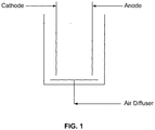
- Electro-bioreactor ( Fig. 1 ) comprises two electrodes immersed in an activated sludge reactor.
- the material of the anode is aluminum and the material of the cathode can be iron.
- DC direct current
- Each reaction can play a role in removing the targeted nutrients.
- three major operating conditions can be considered in order to create the optimal conditions for the removal of C, P, and N:
- CD Current density
- Dissolved oxygen (DO) concentration can be adjusted in order to create different levels of oxidation-reduction potential (ORP) and promote different bacterial genotypes responsible for the transformation of N and P in the system. For example, such a level can be adjusted by injecting air in the wastewater to be treated.
- ORP oxidation-reduction potential
- Carbon removal can be achieved in the reactor through the oxidation of organic material by the biomass.
- biodegradation is not the sole possible removal pathway of carbon.
- the anode comprises Al
- the produced Al +3 can react with the free OH - in water to initially form monomeric species such as Al(OH) +2 , Al(OH) 2 +1 and Al(OH) 4 - .
- these species can be converted into polymeric species such as Al 8 (OH) 20 +4 , Al 13 (OH) 34 +5 , which eventually can be transformed into a long chain of Al(OH) (s) .
- These cationic hydroxide complexes can effectively adsorb the negatively charged organic materials through the electrostatic forces, particularly those colloids of non-biodegradable nature.
- the anode comprises Al
- phosphorus removal can be achieved through the formation of AlPO 4 solids or forming complexes with AI(OH)s.
- AI(OH)s phosphorus becomes part of the suspended solids (inorganic solids) of the system that could be recovered after the solid liquid separation using either a clarifier or membrane modules.
- biological removal is highly expected to take place because of the capability of the system to work at alternating levels of ORP.
- ORP could be adjusted (due to a combination of electrical and air supply systems) to fluctuate within the anaerobic, anoxic and aerobic conditions, which in return promotes different sorts of bacteria species responsible for complete transforming of ammonium from the influent wastewater into nitrogen gas.
- Table 1 Optimal oxidation-reduction potential (ORP) for different biological processes Biological process Cond itions Optimum ORP Nitrification Aerobic +100 to +350 Denitrification Anoxic -50 to +50 P-removal Anaerobic stage -100 to -225 Aerobic stage +25 to +250
- Electrokinetic phenomena applied to wastewater can regulate ORP levels to promote the simultaneous removal of C, P and N. Without wishing to be bound to such a theory, it can be said that during the processes described in the present document, the mechanism of such an electrical process can, for example, undergo six steps.
- Step 1 Once the DC field is activated, the electrons can be discharged from the anode zone (reaction 1 and 2). Since the dissolved oxygen molecules have the highest electro-negativity (affinity to gain electrons) in the system, most of these discharged electrons can react with the dissolved oxygen (reaction 4) to produce hydroxyl ions. In the electrochemical systems, reaction 4 proceeds reaction 3 until DO is consumed at the cathode surface.
- Step 2 For example, in the case that the concentration of DO in the reactor is too high, the high buffering capacity of the reactor can consume all the electrons and can still hold enough oxygen to act as the major electron acceptor for the biological reactions. In that case, the ORP can stay high (>+100) and it can promote only the autotrophic nitrification process that transforms ammonium into nitrate in the system (reactions 5 and 6 with bacterial species given just as an example of ammonia oxidizers and nitrite oxidizers).
- Step 3 For example, in the case that the dissolved oxygen in the reactor is not too high, the discharged electrons can react with DO until not enough oxygen is available to support the aerobic condition to act as the major electron acceptor. As a result, nitrate as electron acceptor can appear in the system and the ORP can drop from the aerobic limit to the anoxic limit (+50 to -50 mV). At this level of ORP, the heterotrophic nitrifiers can become active and start the conversion of nitrate into N 2 gas.
- Step 4 To make the system even more powerful and enhance the nitrification potential of the system, the influx of electrons and dissolved oxygen levels can be adjusted for example to lower the ORP of -150 mV. At this level of redox potential, the autotrophic anaerobic ammonium oxidation (anammox) can be activated and starts to nitrify the ammonium using the already existing nitrite in the system as an electron acceptor (reaction 8).
- ORP profile is achievable through activating the DC field for some time (time-ON) at a current density strong enough to produce enough electrons to satisfy oxygen needs of electrons and neutralize its function as the major electron acceptor. Afterwards, NO 3 - can start to take over the role as the major electron acceptor and later nitrite at the anammox conditions. Once this limit is reached, the DC field is deactivated so that no more electrons can be discharged. Then, the system is given enough time (time-OFF) to recover its oxygen content to a level that can support the aerobic conditions after which another cycle starts to repeat the process once again.
- Step 6 another pathway of N removal in the system is the hydrogen trophic denitrification in which some bacteria species can be capable of using the H 2 gas produced at the cathode (reaction 3) as electron donor and nitrate as electron acceptor to denitrify it into N 2 gas (reaction 9).
- reaction 9 the hydrogen trophic denitrification in which some bacteria species can be capable of using the H 2 gas produced at the cathode (reaction 3) as electron donor and nitrate as electron acceptor to denitrify it into N 2 gas (reaction 9).
- reaction 9 2NO 3 - + 5H 2 + 2H + ⁇ N 2 + 6H 2 O (hydrogen trophic denitrification)
- ORP for promoting the removal of nutrients and carbon
- continuous flow reactor including completely mixed activated sludge reactor and membrane bioreactor.
- SMEBR submerged membrane module
- SMEBR submerged membrane electro-bioreactor
- MLR submerged membrane bioreactor
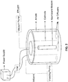
- Two cylindrical perforated electrodes (aluminum anode and stainless steel cathode) were placed around the membrane as demonstrated in Fig. 2 .
- Direct current power supply connected with an electrical timer was applied to provide the required current density and exposure mode (time-ON/time-OFF).
- Vacuum pump was connected to the membrane outlet to extract the liquid phase of the sludge liquor at a constant flow rate.
- the influent synthetic wastewater had different sources for nitrogen, for example, chemically bound nitrogen (easily dissolving ammonium sulfate) and organic compounds rich in ammonium (yeast extract and peptone) that release nitrogen in the ammoniacal form once degraded by the biomass.
- chemically bound nitrogen easily dissolving ammonium sulfate
- organic compounds rich in ammonium yeast extract and peptone
- Run 2 consisted of Run 2a performed at hydraulic retention time (HRT) of 12.8 h and Run 2b at longer HRT of 24 h.
- Run 3 was operated based on glucose as a carbon source and ammonium sulfate as the sole source of ammonium in order to know exactly the concentration of ammonium in the influent.
- This run was conducted for evaluating the nitrification potential of the SMEBR and the control MBR. SMEBR was expected to exhibit higher nitrification potential due to the electrokinetic steps (electrical activation of different types of N transforming bacteria).
- the activated sludge was brought from the activated sludge reactor in the wastewater treatment plant just before starting the experiments.
- the mixed liquor concentration (MLSS) was adjusted between 2000 to 3000 mg/L before used in the reactors. No sludge whatsoever was disposed except for the sludge sampled for analyses. When the MLSS concentration increased to a sufficiently high level that causes high membrane fouling rate, the MLSS concentration was diluted to maintain a reasonable fouling rate. This allowed studying the impact of electrical operating conditions on the reactor performance at different MLSS as well. Samples were taken periodically from the influent, effluent and from the sludge supernatant (after centrifugation at 4000 rpm for 20 minutes). Sludge pH, electrical conductivity (EC) and DO were measured continuously.
- EC electrical conductivity
- Complete transformation of N into gas in one reactor can require the fluctuation of the ORP between the anoxic/anammox and the aerobic conditions.
- the electrical operating parameters current density, voltage gradient and exposure mode
- HRT and MLSS which determines the biological oxygen demand and the diffusivity of gases in the system.
- Obtaining an ORP fluctuating between -150 to +150 mV can be achieved at different levels of DO based on the operating conditions. For example, working at low MLSS requires high DO concentration because the diffusivity of electrons in the reactor is high and can easily reach the DO and deactivate its role as the dominant electron acceptor.
- Run 2 was operated at an influent total nitrogen (TN) of 57 mg-N/L split between the organic N (yeast extract and peptone) and inorganic ammonium sulfate.
- TN influent total nitrogen
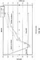
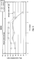
- Run 2b was the continuation of Run 2a but at longer HRT of 24 h, and the ORP profile was adjusted in SMEBR between -100 to +150 mV starting on day 33 to support the simultaneous nitrification/denirtification conditions ( Figs. 6 and 7 ).
- typical nitrification condition led to more than 99% conversion of ammonium into nitrate, and the concentration of nitrate was almost higher than 40 mg-NO 3 - /L.
- the SMEBR proved the possibility of achieving almost complete nitrification of ammonium and complete denitrification of nitrate if the loading of ammonium into the reactor is lower than the nitrification capacity of the system, which was the case in that run.
- the removal efficiency of TN was up to 97% on day 40.
- Run 3 was conducted to examine the nitrification potential of SMEBR and MBR.
- ammonium sulfate was used as the sole source of ammonium in order to assess the nitrification potential of each reactor.
- SMEBR operated at DO of 1 to 2.5 mg/L and ORP fluctuating between -100 to 150 mV
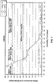
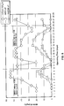
- an increase of up to 10% in the nitrification potential was achieved because of combined aerobic and anaerobic nitrification in the SMEBR compared to only aerobic nitrification in the MBR ( Figs. 8 and 9 ).
- the MBR produced effluent with 11 mg- NH 4 -N/L, 5 mg- NO 3 - /L and total nitrogen of 20.8 mg-N/L
- the SMEBR produced effluent with 0.2 mg NH 4 -N/L, 0.02 mg NO 3 - /L and total nitrogen of 1 mg-N/L.
- the total nitrogen removal efficiency of the SMEBR was higher than 97% when the ammonium loading was less than 47 NH 4 + -N mg/L.d.
- SMEBR denitrification was carried out in two different biological processes.
- the first process is the heterotrophic denitrification in which carbon is taken from the organic materials and nitrate serve as e-acceptor.
- the other denitrification process in SMEBR is through the autotrophic hydrogen denitrification in which the hydrogen produced at the cathode acts as electron donor and nitrate as electron acceptor.
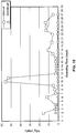
- a small experiment was conducted. In that experiment, the SMEBR was fed with an influent of high nitrate concentration and very low organic carbon source for 7 days ( Fig. 11 ). On day 8, the influent was enriched with organic carbon.
- anammox process using nitrite from the incomplete nitrification as electron acceptor helped in reducing the production of nitrate in the reactor. Therefore, anammox with the other two denitrification processes (heterotrophic and H-denitrification) working simultaneously in one reactor ensured an effluent with a very low nitrate concentration, which was the case in this example.
- electro-bioreactor and processes of the disclosure provided extra benefits to the treatment process. These benefits include better sludge filterability and dewaterability, better flocs settleability, less soluble microbial products and colloidal materials in the sludge supernatant, a lower membrane fouling rate and thus better effluent quality. Electrical field, once applied properly, is able to change sludge characteristics through its versatile electro-kinetic processes that are taking place in the reactor such as electroosmosis, electrocoagulation and electrochemical reactions, and ultimately enhances its quality.
- Electrokinetic treatment for the removal of C, P and N in one reactor can be installed as part of the new plants or in the retrofitting of the old ones.
- the processes described in the present disclosure are quite versatile and be carried out with a various different types of reactors.
- it can be used using an existing reactor of a company or a plant, thereby significantly reducing the involved costs for such a company.
- It could be applied with or without membrane modules.
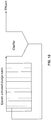
- the electrodes can be placed in parallel (rectangular shape) as in Fig. 12 or in circular configuration (see Fig. 2 concerning a circular configuration).
- the membranes could be placed in the middle of the circular electrodes or any other place rather than the electrical zone.
- the electrical zone can compromise 10 to 80% of the total reactor volume.
- the current density can be less than 50 A/m 2 , at exposure modes 5'-ON-20'-OFF.
- Aluminum anodes in conjunction with other electrokinetic processes can effectively remove P and with controlled aerated system will provide suitable fluctuation of ORP based on the other operating conditions (HRT, MLSS, organic loading and solid retention time).
- the reactor has run for 5 months at a constant flow of 45 L/d and SRT of 15 days.
- the system was able to remove COD, phosphorous, ammonia by 99%, 99.7%, 99.7% respectively at equilibrium conditions. Entire removal of nitrates was also achieved simultaneously ( Fig. 13 ).
- This experiment confirmed that the described processes are capable of simultaneous removal in the same electro-bioreactor of carbon, nitrogen and phosphorus. Furthermore, the system is efficient in various electrodes configurations as indicated in the present disclosure.
- a PVC cylindrical reactor (235 L), two cylindrical electrodes connected to a low DC power supply (intermittent supply of electrical field), and a hollow fiber microfiltration membrane (MUNC-600A, Microza, Asahi Kasei Chem. Corp., Japan) were used (see Fig. 2 ).
- the membrane had an effective surface area of 12.5 m 2 , a pore size of 0.1 ⁇ m, and the module was equipped with a built-in bottom air diffuser for scouring. Several fine bubble air diffusers were also placed at the bottom of the reactor to supply the oxygen required for both mixing and microbial activity.
- SMEBR was continuously fed with pre-screened raw municipal wastewater containing metals (see Tables 2 and 3) redirected from the influent channel at a flow rate of 550 L/d for 7 weeks.
- SRT and HRT were 10 d and 11 h, respectively.
- SMEBR operated under constant current density less than 20 A/m 2 , and volume of electrical zone to volume of the reactor was no higher than 0.5.
- Table 2 Characteristics of influents during the testing period Parameters SMEBR PO 4 3- -P, mg/L 4.13 ⁇ 1.84 NH 3 + -N, mg/L 42.9 ⁇ 11.2 NO 3 - -N, mg/L 0.41 ⁇ 0.11 COD, mg/L 316 ⁇ 145.9 Table 3.
- Dissolved oxygen (DO), pH values, temperature, electrical current and voltage were continuously monitored. Samples from influent raw wastewater and treated effluent were collected four times per week and tested for COD, phosphorus, and ammonia, using Hach TNT vials. Samples were repeated twice and an average value was recorded. At the last stage of the SMEBR pilot test, metals such as Ni, Pb, Cd, Cu, Fe, Ca, Mg and Zn were also measured after digestion with nitric acid digested in samples of influent and effluent using an Atomic Absorption Spectrometer. (Perkin Elmer, Analyst 100).Readings were repeated three times for each sample and average values were reported. The handheld NITON XRF analyzer was used to identify the elements present in electrode deposits as well as in the biosolids.
- Nitrification potential was enhanced up to 25% in the SMEBR due to the activation of anammox as another nitrification process working in harmony with the aerobic nitrifiers, while the SMBR does the nitrification only through the autotrophic nitrification.
- Electrokinetics could be incorporated into already established facilities reducing any additional infrastructure.
- This upgrading process requires the immersion of the electrodes (at adequate distances) into the activated sludge basin to upgrade its performance and the effluent quality.
- the electro-bioreactor consumes low energy because the system works at low current density, low voltage and intermittent exposure to the electrical field.
- removal of the major environmentally hazardous nutrients in addition to the improvement of sludge characteristics in one single reactor is an important advancement in wastewater treatment technology that should be considered whenever better treatment quality is the concern.
- the processes of the present disclosure can be applied to different treatment systems with different electrodes' configuration. They can be applied in combination with or without membranes.
- the membranes can be submerged and located within the center of the same reactor where electrodes are installed in circular or none circular form.
- the submerged membranes can also be located in different sides of a hybrid reactor in any justified position with respect to the electrodes (which can be flat or circular, perforated or not).
- the processes can be performed in electrode system sidewise, sideways or side by side (in separate compartments) with respect to membranes.
- the processes can also be performed in a separated compartment with electrodes located before or after any other wastewater treatment method.
Landscapes
- Life Sciences & Earth Sciences (AREA)
- Chemical & Material Sciences (AREA)
- Organic Chemistry (AREA)
- Hydrology & Water Resources (AREA)
- Engineering & Computer Science (AREA)
- Environmental & Geological Engineering (AREA)
- Water Supply & Treatment (AREA)
- Microbiology (AREA)
- Biodiversity & Conservation Biology (AREA)
- Chemical Kinetics & Catalysis (AREA)
- Electrochemistry (AREA)
- General Chemical & Material Sciences (AREA)
- Health & Medical Sciences (AREA)
- Molecular Biology (AREA)
- Water Treatment By Electricity Or Magnetism (AREA)
- Purification Treatments By Anaerobic Or Anaerobic And Aerobic Bacteria Or Animals (AREA)
Claims (7)
- Verfahren zur Behandlung von Abwasser, wobei das Verfahren folgendes umfasst:Behandeln eines Gemischs, das Abwasser und einen aktivierten Schlamm umfasst, in einem einzelnen Reaktor, mit einem elektrischen Strom mit einer Dichte von 15 bis 20 A/m2 durch mindestens eine Anode und mindestens eine Kathode, die dazwischen eine elektrische Zone zur Behandlung des Gemischs definieren; wobei die Anode eine Aluminiumanode ist;Aussetzen des Gemisches einem intermittierenden elektrischen EIN/AUS-Expositionsmodus des elektrischen Stroms, wobei ein AUS-Zeitraum 15 bis 25 Minuten beträgt, und wobei ein EIN-Zeitraum 4 bis 6 Minuten beträgt; wobei jeder elektrische Zyklus unterteilt ist in 50% typischer anoxischer Bedingungen, gefolgt von 50% typischer aerober Bedingungen; undAufrechterhalten eines Redoxpotenzials, so dass dieses in dem einzelnen Reaktor zwischen -150 mV und +150 mV schwankt, bei einer DO-Konzentration von 0,3 bis 2,5 mg/Liter;wodurch eine substantielle Entfernung von Kohlenstoff, Stickstoff und Phosphor aus dem Abwasser in dem einzelnen Reaktor ebenso ermöglicht wird wie das Erhalten eines weiteren Gemischs, das ein behandeltes Abwasser und Feststoffe umfasst.
- Verfahren nach Anspruch 1, wobei das Verfahren mit einem Gradientenspannung von 0,1 V/cm bis 20 V/cm durchgeführt wird.
- Verfahren nach Anspruch 1 oder 2, wobei während der Behandlung der in dem Abwasser enthaltene Stickstoff in N2 umgewandelt und von dem Abwasser getrennt wird.
- Verfahren nach einem der Ansprüche 1 bis 3, das ferner das Abscheidend es behandelten Abwassers von den Feststoffen umfasst.
- Verfahren nach einem der Ansprüche 1 bis 4, wobei das Verfahren das Anpassen der Elektrokinetik und der aufgelösten Sauerstoffkonzentration umfasst, um die Aktivität unterschiedlicher Arten von Mikroorganismen zu steuern, die für wenigstens einen biologischen Prozess in dem Reaktor verantwortlich sind.
- Verfahren nach Anspruch 5, wobei der wenigstens eine biologische Prozess in der Reaktion ausgewählt ist aus dem Entfernen von Kohlenstoff und dem Entfernen von Phosphor.
- Verfahren nach einem der Ansprüche 1 bis 6, wobei das Verfahren das Anpassen der Elektrokinetik und der aufgelösten Sauerstoffkonzentration umfasst, um die Aktivität aerober Nitrifizierer, Anammox-Nitrifizierer, heterotropher Nitrifizierer und Wasserstoff-tropher Denitrifizierer in dem Reaktor zu steuern.
Applications Claiming Priority (2)
| Application Number | Priority Date | Filing Date | Title |
|---|---|---|---|
| US201261596471P | 2012-02-08 | 2012-02-08 | |
| PCT/CA2013/000113 WO2013116935A1 (en) | 2012-02-08 | 2013-02-08 | Processes and apparatuses for removal of carbon, phosphorus and nitrogen |
Publications (3)
| Publication Number | Publication Date |
|---|---|
| EP2812286A1 EP2812286A1 (de) | 2014-12-17 |
| EP2812286A4 EP2812286A4 (de) | 2015-10-14 |
| EP2812286B1 true EP2812286B1 (de) | 2020-06-10 |
Family
ID=48918172
Family Applications (1)
| Application Number | Title | Priority Date | Filing Date |
|---|---|---|---|
| EP13746700.7A Active EP2812286B1 (de) | 2012-02-08 | 2013-02-08 | Verfahren zur beseitigung von kohlenstoff, phosphor und stickstoff |
Country Status (4)
| Country | Link |
|---|---|
| US (1) | US9771281B2 (de) |
| EP (1) | EP2812286B1 (de) |
| CA (2) | CA2795655A1 (de) |
| WO (1) | WO2013116935A1 (de) |
Families Citing this family (31)
| Publication number | Priority date | Publication date | Assignee | Title |
|---|---|---|---|---|
| CN104031905A (zh) * | 2014-06-24 | 2014-09-10 | 大连理工大学 | 一种通过电场强化厌氧氨氧化细菌活性方法 |
| TWI760562B (zh) | 2017-09-14 | 2022-04-11 | 美商伊芙卡水科技有限公司 | 在序列批式反應器應用中同時硝化作用/脫氮作用(sndn) |
| CN107500422A (zh) * | 2017-10-11 | 2017-12-22 | 上海应用技术大学 | 基于厌氧氨氧化的生活污水级联池及人工湿地净化方法 |
| CN107827209A (zh) * | 2017-11-09 | 2018-03-23 | 中国恩菲工程技术有限公司 | 电絮凝废水处理装置及电絮凝废水处理工艺 |
| US10981817B2 (en) * | 2018-01-19 | 2021-04-20 | National Research Council Of Canada | Wastewater treatment with in-film microbial heating |
| FI128091B (en) * | 2018-04-22 | 2019-09-13 | Timo Korpela | Wastewater treatment and disinfection by combined flotation |
| CN109336328B (zh) * | 2018-10-29 | 2024-02-06 | 浙江利欧环保科技有限公司 | 一种生物电化学同步脱氮除磷装置及其方法 |
| CN109621905A (zh) * | 2018-12-07 | 2019-04-16 | 浙江精安再生资源发展有限公司 | 一种玉米芯改性材料的制备方法及其应用 |
| CN111573830A (zh) * | 2019-02-18 | 2020-08-25 | 桂林理工大学 | 厌氧氨氧化与氢自养反硝化耦合深度脱氮的装置与方法 |
| CN109694132B (zh) * | 2019-02-23 | 2021-12-17 | 何江涛 | 一种序批控温控压生物膜的污水处理方法 |
| CN110029075A (zh) * | 2019-03-19 | 2019-07-19 | 哈尔滨工业大学 | 一种利用活性污泥快速富集厌氧氨氧化菌的培养基及其制备方法与应用 |
| US10713455B1 (en) | 2019-03-27 | 2020-07-14 | Toshiba Global Commerce Solutions | Point-of-sale terminal with mirrors arranged around scan zone |
| EP3983342A4 (de) | 2019-06-12 | 2023-06-21 | Phosphorus Free Water Solutions, LLC | Entfernung von materialien aus wasser |
| US12351492B2 (en) | 2019-06-12 | 2025-07-08 | Nuquatic, Llc | Removal of materials from water |
| CN111320259B (zh) * | 2020-03-27 | 2022-03-08 | 太原学院 | 微氧颗粒污泥与生物电极耦合焦化废水强化处理方法及处理装置 |
| CN111573834A (zh) * | 2020-05-22 | 2020-08-25 | 盐城工学院 | 一种基于短程反硝化电极协同厌氧氨氧化脱氮的反应器 |
| CN111573821A (zh) * | 2020-05-22 | 2020-08-25 | 盐城工学院 | 一种基于自养短程反硝化-厌氧氨氧化模块电极脱氮系统 |
| CN111634994B (zh) * | 2020-06-11 | 2022-07-05 | 武汉轻工大学 | 提高难降解有机废水可生化性的反应器、系统以及方法 |
| CN111807503A (zh) * | 2020-07-20 | 2020-10-23 | 南京神克隆水务有限公司 | 一种氧限制型微生物脱盐池及废水处理方法 |
| CN112028223B (zh) * | 2020-08-12 | 2023-01-24 | 武汉理工大学 | 耦合活性污泥与生物膜法的微生物电化学苯胺废水处理系统及方法 |
| CN112591877A (zh) * | 2020-12-23 | 2021-04-02 | 天津工业大学 | 用于分散型污水脱氮除磷的膜生物反应器及污水处理方法 |
| US11401181B1 (en) | 2021-03-02 | 2022-08-02 | Phosphorus Free Water Solutions, Llc | Galvanic process for treating aqueous compositions |
| CN113003877B (zh) * | 2021-03-10 | 2023-03-17 | 浙江工商大学 | 一种难降解有机废水的处理装置及方法 |
| CN113024031A (zh) * | 2021-03-12 | 2021-06-25 | 江西绿建环保科技有限公司 | 一体式膜耦合-电絮凝污水处理装置 |
| WO2023283112A1 (en) * | 2021-07-05 | 2023-01-12 | Inspired Water Technology Inc. | Wastewater treatment system for improved primary treatment and volatile fatty acid generation |
| CN113461264A (zh) * | 2021-07-08 | 2021-10-01 | 中持水务股份有限公司 | 一种偶联生物调控脱氮系统及其使用方法 |
| EP4688667A2 (de) | 2023-04-05 | 2026-02-11 | NuQuatic, LLC | Behandlung einer wässrigen zusammensetzung mit einer metallkomponente |
| WO2024211729A1 (en) | 2023-04-05 | 2024-10-10 | Nuquatic, Llc | Removal of fluoro alkyl compounds from water using galvanic cell |
| CN117401829B (zh) * | 2023-10-20 | 2025-04-15 | 东莞理工学院 | 一种培养厌氧氨氧化菌增殖的装置及培养方法 |
| CN118495660A (zh) * | 2024-05-11 | 2024-08-16 | 浙江工业大学 | 铁碳微电解介导短程反硝化/厌氧氨氧化深度脱氮除磷的装置及方法 |
| CN118420112B (zh) * | 2024-05-13 | 2026-04-24 | 中国科学院生态环境研究中心 | 一种富铁包裹体厌氧氨氧化颗粒以及制备方法和应用 |
Family Cites Families (13)
| Publication number | Priority date | Publication date | Assignee | Title |
|---|---|---|---|---|
| US4755305A (en) * | 1982-03-15 | 1988-07-05 | Champion International Corporation | Continuous dewatering method |
| US5048404A (en) | 1985-05-31 | 1991-09-17 | Foodco Corporation | High pulsed voltage systems for extending the shelf life of pumpable food products |
| DE3838170A1 (de) * | 1988-11-10 | 1990-05-17 | Linde Ag | Verfahren und vorrichtung zur elektrobiologischen umsetzung von stoffen |
| US5695650A (en) | 1995-11-02 | 1997-12-09 | Held; Jeffery S. | Method for dewatering previously-dewatered municipal waste-water sludges using high electrical voltage |
| US6395176B1 (en) | 1995-11-02 | 2002-05-28 | D-H2O L.L.C. | Method for treating waste-activated sludge using electroporation |
| US6274028B1 (en) | 1999-04-23 | 2001-08-14 | Clyde Kuen-Hua Hu | Electrolytic wastewater treatment method and apparatus |
| US6645366B2 (en) | 2000-11-01 | 2003-11-11 | Sanyo Electric Co., Ltd. | Waste water treatment device |
| US7429328B2 (en) | 2001-03-02 | 2008-09-30 | Advanced Treatment Sciences, Inc. | Apparatus and methods for control of waste treatment processes |
| KR100767724B1 (ko) | 2006-07-04 | 2007-10-18 | 한국과학기술연구원 | 슬러지 부상분리를 통한 생물학적 하폐수 처리 방법 및 장치 |
| CA2729599C (en) * | 2008-06-26 | 2020-03-10 | David Rigby | Electrochemical system and method for the treatment of water and wastewater |
| US8147700B2 (en) | 2008-09-04 | 2012-04-03 | Maria Elektorowicz | Wastewater treatment system and method |
| JP5629900B2 (ja) * | 2009-06-16 | 2014-11-26 | カンブリアン イノベーションズ インコーポレイデッド | 水、廃水、および他の生物分解物質を処理し監視するシステムおよび装置 |
| CA2835727C (en) | 2011-06-06 | 2020-07-21 | Axine Water Technologies Inc. | Efficient treatment of wastewater using electrochemical cell |
-
2012
- 2012-11-09 CA CA 2795655 patent/CA2795655A1/en not_active Abandoned
-
2013
- 2013-02-08 EP EP13746700.7A patent/EP2812286B1/de active Active
- 2013-02-08 WO PCT/CA2013/000113 patent/WO2013116935A1/en not_active Ceased
- 2013-02-08 CA CA2894617A patent/CA2894617C/en active Active
- 2013-02-08 US US14/377,465 patent/US9771281B2/en active Active
Non-Patent Citations (1)
| Title |
|---|
| None * |
Also Published As
| Publication number | Publication date |
|---|---|
| US20150001094A1 (en) | 2015-01-01 |
| CA2894617C (en) | 2017-11-28 |
| EP2812286A1 (de) | 2014-12-17 |
| EP2812286A4 (de) | 2015-10-14 |
| US9771281B2 (en) | 2017-09-26 |
| CA2894617A1 (en) | 2013-08-15 |
| CA2795655A1 (en) | 2013-08-08 |
| WO2013116935A1 (en) | 2013-08-15 |
Similar Documents
| Publication | Publication Date | Title |
|---|---|---|
| US9771281B2 (en) | Processes and apparatuses for removal of carbon, phosphorus and nitrogen | |
| EP3747836B1 (de) | Anaerobes ammoniakoxidationsbasiertes abwasserbehandlungsverfahren unter verwendung von mbr | |
| Udomkittayachai et al. | Electroconductive moving bed membrane bioreactor (EcMB-MBR) for single-step decentralized wastewater treatment: Performance, mechanisms, and cost | |
| KR101831900B1 (ko) | 폐수 내 질소 제거 방법 | |
| KR101378539B1 (ko) | 호기성 입상슬러지를 이용한 역삼투공정의 농축수 처리장치 및 방법 | |
| Wei et al. | Nutrient removal in an electrically enhanced membrane bioreactor | |
| Lagum | Simultaneous nitrification and denitrification by controlling current density and dissolved oxygen supply in a novel electrically-induced membrane bioreactor | |
| KR20170010679A (ko) | 전해산화에 의한 가축분뇨 처리시스템 및 그 처리방법 | |
| Lee et al. | Biological nitrogen and phosphorus removal in UCT-type MBR process | |
| Zheng et al. | Effect of blending landfill leachate with activated sludge on the domestic wastewater treatment process | |
| CN109336328B (zh) | 一种生物电化学同步脱氮除磷装置及其方法 | |
| KR100767724B1 (ko) | 슬러지 부상분리를 통한 생물학적 하폐수 처리 방법 및 장치 | |
| Watanabe et al. | Simultaneous nitrification and denitrification in a single reactor using bio-electrochemical process | |
| CN102491597B (zh) | 一种处理含氮高浓度有机废水的方法 | |
| CN219885873U (zh) | 设备化的煤化废水处理系统 | |
| Lagum et al. | Coupling membrane electro-bioreactor with anammox process to treat wastewater at low temperatures | |
| US20120048802A1 (en) | Non-aerated biodestruction of biochemical oxygen demand | |
| CN114314809A (zh) | 一种分散型污水处理装置与方法 | |
| CN113860645A (zh) | 一种高浓度难降解有机废水处理方法 | |
| KR102004483B1 (ko) | 난분해성 유기폐수 또는 소화조 탈리액 처리장치 | |
| KR20080019975A (ko) | 생물학적 활성조 및 전극시스템이 결합된 하이브리드형생물―전기화학적 생물막 연속회분식 반응기를 이용한오폐수 처리장치 | |
| CN104016548A (zh) | 一种焦化废水生化处理工艺 | |
| Ibeid et al. | Upscaling an electro-bioreactor with rectangular electrodes for single-stage simultaneous removal of ammonia, nitrate and phosphorous from wastewater | |
| Shin et al. | Performance assessment of a combined system using a biological aerated filter and electro-coagulation for advanced wastewater treatment | |
| KR101931346B1 (ko) | 역삼투막 농축수 처리시설을 구비한 막분리 수처리 시스템 |
Legal Events
| Date | Code | Title | Description |
|---|---|---|---|
| PUAI | Public reference made under article 153(3) epc to a published international application that has entered the european phase |
Free format text: ORIGINAL CODE: 0009012 |
|
| 17P | Request for examination filed |
Effective date: 20140904 |
|
| AK | Designated contracting states |
Kind code of ref document: A1 Designated state(s): AL AT BE BG CH CY CZ DE DK EE ES FI FR GB GR HR HU IE IS IT LI LT LU LV MC MK MT NL NO PL PT RO RS SE SI SK SM TR |
|
| AX | Request for extension of the european patent |
Extension state: BA ME |
|
| DAX | Request for extension of the european patent (deleted) | ||
| RA4 | Supplementary search report drawn up and despatched (corrected) |
Effective date: 20150910 |
|
| RIC1 | Information provided on ipc code assigned before grant |
Ipc: C02F 1/46 20060101AFI20150904BHEP Ipc: C02F 3/30 20060101ALI20150904BHEP Ipc: C02F 1/48 20060101ALI20150904BHEP Ipc: C02F 3/20 20060101ALI20150904BHEP Ipc: C02F 3/12 20060101ALI20150904BHEP |
|
| STAA | Information on the status of an ep patent application or granted ep patent |
Free format text: STATUS: EXAMINATION IS IN PROGRESS |
|
| 17Q | First examination report despatched |
Effective date: 20180413 |
|
| GRAP | Despatch of communication of intention to grant a patent |
Free format text: ORIGINAL CODE: EPIDOSNIGR1 |
|
| STAA | Information on the status of an ep patent application or granted ep patent |
Free format text: STATUS: GRANT OF PATENT IS INTENDED |
|
| INTG | Intention to grant announced |
Effective date: 20200110 |
|
| GRAS | Grant fee paid |
Free format text: ORIGINAL CODE: EPIDOSNIGR3 |
|
| GRAA | (expected) grant |
Free format text: ORIGINAL CODE: 0009210 |
|
| STAA | Information on the status of an ep patent application or granted ep patent |
Free format text: STATUS: THE PATENT HAS BEEN GRANTED |
|
| AK | Designated contracting states |
Kind code of ref document: B1 Designated state(s): AL AT BE BG CH CY CZ DE DK EE ES FI FR GB GR HR HU IE IS IT LI LT LU LV MC MK MT NL NO PL PT RO RS SE SI SK SM TR |
|
| REG | Reference to a national code |
Ref country code: GB Ref legal event code: FG4D |
|
| REG | Reference to a national code |
Ref country code: AT Ref legal event code: REF Ref document number: 1279044 Country of ref document: AT Kind code of ref document: T Effective date: 20200615 Ref country code: CH Ref legal event code: EP |
|
| REG | Reference to a national code |
Ref country code: DE Ref legal event code: R096 Ref document number: 602013069773 Country of ref document: DE |
|
| REG | Reference to a national code |
Ref country code: IE Ref legal event code: FG4D |
|
| REG | Reference to a national code |
Ref country code: LT Ref legal event code: MG4D |
|
| PG25 | Lapsed in a contracting state [announced via postgrant information from national office to epo] |
Ref country code: SE Free format text: LAPSE BECAUSE OF FAILURE TO SUBMIT A TRANSLATION OF THE DESCRIPTION OR TO PAY THE FEE WITHIN THE PRESCRIBED TIME-LIMIT Effective date: 20200610 Ref country code: NO Free format text: LAPSE BECAUSE OF FAILURE TO SUBMIT A TRANSLATION OF THE DESCRIPTION OR TO PAY THE FEE WITHIN THE PRESCRIBED TIME-LIMIT Effective date: 20200910 Ref country code: GR Free format text: LAPSE BECAUSE OF FAILURE TO SUBMIT A TRANSLATION OF THE DESCRIPTION OR TO PAY THE FEE WITHIN THE PRESCRIBED TIME-LIMIT Effective date: 20200911 Ref country code: FI Free format text: LAPSE BECAUSE OF FAILURE TO SUBMIT A TRANSLATION OF THE DESCRIPTION OR TO PAY THE FEE WITHIN THE PRESCRIBED TIME-LIMIT Effective date: 20200610 Ref country code: LT Free format text: LAPSE BECAUSE OF FAILURE TO SUBMIT A TRANSLATION OF THE DESCRIPTION OR TO PAY THE FEE WITHIN THE PRESCRIBED TIME-LIMIT Effective date: 20200610 |
|
| REG | Reference to a national code |
Ref country code: NL Ref legal event code: MP Effective date: 20200610 |
|
| PG25 | Lapsed in a contracting state [announced via postgrant information from national office to epo] |
Ref country code: LV Free format text: LAPSE BECAUSE OF FAILURE TO SUBMIT A TRANSLATION OF THE DESCRIPTION OR TO PAY THE FEE WITHIN THE PRESCRIBED TIME-LIMIT Effective date: 20200610 Ref country code: HR Free format text: LAPSE BECAUSE OF FAILURE TO SUBMIT A TRANSLATION OF THE DESCRIPTION OR TO PAY THE FEE WITHIN THE PRESCRIBED TIME-LIMIT Effective date: 20200610 Ref country code: RS Free format text: LAPSE BECAUSE OF FAILURE TO SUBMIT A TRANSLATION OF THE DESCRIPTION OR TO PAY THE FEE WITHIN THE PRESCRIBED TIME-LIMIT Effective date: 20200610 Ref country code: BG Free format text: LAPSE BECAUSE OF FAILURE TO SUBMIT A TRANSLATION OF THE DESCRIPTION OR TO PAY THE FEE WITHIN THE PRESCRIBED TIME-LIMIT Effective date: 20200910 |
|
| REG | Reference to a national code |
Ref country code: AT Ref legal event code: MK05 Ref document number: 1279044 Country of ref document: AT Kind code of ref document: T Effective date: 20200610 |
|
| PG25 | Lapsed in a contracting state [announced via postgrant information from national office to epo] |
Ref country code: AL Free format text: LAPSE BECAUSE OF FAILURE TO SUBMIT A TRANSLATION OF THE DESCRIPTION OR TO PAY THE FEE WITHIN THE PRESCRIBED TIME-LIMIT Effective date: 20200610 Ref country code: NL Free format text: LAPSE BECAUSE OF FAILURE TO SUBMIT A TRANSLATION OF THE DESCRIPTION OR TO PAY THE FEE WITHIN THE PRESCRIBED TIME-LIMIT Effective date: 20200610 |
|
| PG25 | Lapsed in a contracting state [announced via postgrant information from national office to epo] |
Ref country code: EE Free format text: LAPSE BECAUSE OF FAILURE TO SUBMIT A TRANSLATION OF THE DESCRIPTION OR TO PAY THE FEE WITHIN THE PRESCRIBED TIME-LIMIT Effective date: 20200610 Ref country code: AT Free format text: LAPSE BECAUSE OF FAILURE TO SUBMIT A TRANSLATION OF THE DESCRIPTION OR TO PAY THE FEE WITHIN THE PRESCRIBED TIME-LIMIT Effective date: 20200610 Ref country code: PT Free format text: LAPSE BECAUSE OF FAILURE TO SUBMIT A TRANSLATION OF THE DESCRIPTION OR TO PAY THE FEE WITHIN THE PRESCRIBED TIME-LIMIT Effective date: 20201012 Ref country code: ES Free format text: LAPSE BECAUSE OF FAILURE TO SUBMIT A TRANSLATION OF THE DESCRIPTION OR TO PAY THE FEE WITHIN THE PRESCRIBED TIME-LIMIT Effective date: 20200610 Ref country code: CZ Free format text: LAPSE BECAUSE OF FAILURE TO SUBMIT A TRANSLATION OF THE DESCRIPTION OR TO PAY THE FEE WITHIN THE PRESCRIBED TIME-LIMIT Effective date: 20200610 Ref country code: SM Free format text: LAPSE BECAUSE OF FAILURE TO SUBMIT A TRANSLATION OF THE DESCRIPTION OR TO PAY THE FEE WITHIN THE PRESCRIBED TIME-LIMIT Effective date: 20200610 Ref country code: IT Free format text: LAPSE BECAUSE OF FAILURE TO SUBMIT A TRANSLATION OF THE DESCRIPTION OR TO PAY THE FEE WITHIN THE PRESCRIBED TIME-LIMIT Effective date: 20200610 Ref country code: RO Free format text: LAPSE BECAUSE OF FAILURE TO SUBMIT A TRANSLATION OF THE DESCRIPTION OR TO PAY THE FEE WITHIN THE PRESCRIBED TIME-LIMIT Effective date: 20200610 |
|
| PG25 | Lapsed in a contracting state [announced via postgrant information from national office to epo] |
Ref country code: IS Free format text: LAPSE BECAUSE OF FAILURE TO SUBMIT A TRANSLATION OF THE DESCRIPTION OR TO PAY THE FEE WITHIN THE PRESCRIBED TIME-LIMIT Effective date: 20201010 Ref country code: PL Free format text: LAPSE BECAUSE OF FAILURE TO SUBMIT A TRANSLATION OF THE DESCRIPTION OR TO PAY THE FEE WITHIN THE PRESCRIBED TIME-LIMIT Effective date: 20200610 Ref country code: SK Free format text: LAPSE BECAUSE OF FAILURE TO SUBMIT A TRANSLATION OF THE DESCRIPTION OR TO PAY THE FEE WITHIN THE PRESCRIBED TIME-LIMIT Effective date: 20200610 |
|
| REG | Reference to a national code |
Ref country code: DE Ref legal event code: R097 Ref document number: 602013069773 Country of ref document: DE |
|
| PLBE | No opposition filed within time limit |
Free format text: ORIGINAL CODE: 0009261 |
|
| STAA | Information on the status of an ep patent application or granted ep patent |
Free format text: STATUS: NO OPPOSITION FILED WITHIN TIME LIMIT |
|
| PG25 | Lapsed in a contracting state [announced via postgrant information from national office to epo] |
Ref country code: DK Free format text: LAPSE BECAUSE OF FAILURE TO SUBMIT A TRANSLATION OF THE DESCRIPTION OR TO PAY THE FEE WITHIN THE PRESCRIBED TIME-LIMIT Effective date: 20200610 |
|
| 26N | No opposition filed |
Effective date: 20210311 |
|
| PG25 | Lapsed in a contracting state [announced via postgrant information from national office to epo] |
Ref country code: SI Free format text: LAPSE BECAUSE OF FAILURE TO SUBMIT A TRANSLATION OF THE DESCRIPTION OR TO PAY THE FEE WITHIN THE PRESCRIBED TIME-LIMIT Effective date: 20200610 |
|
| PG25 | Lapsed in a contracting state [announced via postgrant information from national office to epo] |
Ref country code: MC Free format text: LAPSE BECAUSE OF FAILURE TO SUBMIT A TRANSLATION OF THE DESCRIPTION OR TO PAY THE FEE WITHIN THE PRESCRIBED TIME-LIMIT Effective date: 20200610 |
|
| PG25 | Lapsed in a contracting state [announced via postgrant information from national office to epo] |
Ref country code: CH Free format text: LAPSE BECAUSE OF NON-PAYMENT OF DUE FEES Effective date: 20210228 Ref country code: LU Free format text: LAPSE BECAUSE OF NON-PAYMENT OF DUE FEES Effective date: 20210208 Ref country code: LI Free format text: LAPSE BECAUSE OF NON-PAYMENT OF DUE FEES Effective date: 20210228 |
|
| PG25 | Lapsed in a contracting state [announced via postgrant information from national office to epo] |
Ref country code: HU Free format text: LAPSE BECAUSE OF FAILURE TO SUBMIT A TRANSLATION OF THE DESCRIPTION OR TO PAY THE FEE WITHIN THE PRESCRIBED TIME-LIMIT; INVALID AB INITIO Effective date: 20130208 |
|
| PG25 | Lapsed in a contracting state [announced via postgrant information from national office to epo] |
Ref country code: CY Free format text: LAPSE BECAUSE OF FAILURE TO SUBMIT A TRANSLATION OF THE DESCRIPTION OR TO PAY THE FEE WITHIN THE PRESCRIBED TIME-LIMIT Effective date: 20200610 |
|
| P01 | Opt-out of the competence of the unified patent court (upc) registered |
Effective date: 20230611 |
|
| PG25 | Lapsed in a contracting state [announced via postgrant information from national office to epo] |
Ref country code: MK Free format text: LAPSE BECAUSE OF FAILURE TO SUBMIT A TRANSLATION OF THE DESCRIPTION OR TO PAY THE FEE WITHIN THE PRESCRIBED TIME-LIMIT Effective date: 20200610 |
|
| PG25 | Lapsed in a contracting state [announced via postgrant information from national office to epo] |
Ref country code: TR Free format text: LAPSE BECAUSE OF FAILURE TO SUBMIT A TRANSLATION OF THE DESCRIPTION OR TO PAY THE FEE WITHIN THE PRESCRIBED TIME-LIMIT Effective date: 20200610 |
|
| PG25 | Lapsed in a contracting state [announced via postgrant information from national office to epo] |
Ref country code: MT Free format text: LAPSE BECAUSE OF FAILURE TO SUBMIT A TRANSLATION OF THE DESCRIPTION OR TO PAY THE FEE WITHIN THE PRESCRIBED TIME-LIMIT Effective date: 20200610 |
|
| PGFP | Annual fee paid to national office [announced via postgrant information from national office to epo] |
Ref country code: DE Payment date: 20250212 Year of fee payment: 13 |
|
| PGFP | Annual fee paid to national office [announced via postgrant information from national office to epo] |
Ref country code: IE Payment date: 20250225 Year of fee payment: 13 |
|
| PGFP | Annual fee paid to national office [announced via postgrant information from national office to epo] |
Ref country code: BE Payment date: 20250214 Year of fee payment: 13 |
|
| PGFP | Annual fee paid to national office [announced via postgrant information from national office to epo] |
Ref country code: FR Payment date: 20250212 Year of fee payment: 13 |
|
| PGFP | Annual fee paid to national office [announced via postgrant information from national office to epo] |
Ref country code: GB Payment date: 20250212 Year of fee payment: 13 |