EP2811797A1 - Système de communication, dispositif station de base, dispositif terminal mobile et procédé de communication - Google Patents
Système de communication, dispositif station de base, dispositif terminal mobile et procédé de communication Download PDFInfo
- Publication number
- EP2811797A1 EP2811797A1 EP13742921.3A EP13742921A EP2811797A1 EP 2811797 A1 EP2811797 A1 EP 2811797A1 EP 13742921 A EP13742921 A EP 13742921A EP 2811797 A1 EP2811797 A1 EP 2811797A1
- Authority
- EP
- European Patent Office
- Prior art keywords
- carrier
- base station
- mobile terminal
- station apparatus
- detection signal
- Prior art date
- Legal status (The legal status is an assumption and is not a legal conclusion. Google has not performed a legal analysis and makes no representation as to the accuracy of the status listed.)
- Granted
Links
Images


Classifications
-
- H—ELECTRICITY
- H04—ELECTRIC COMMUNICATION TECHNIQUE
- H04L—TRANSMISSION OF DIGITAL INFORMATION, e.g. TELEGRAPHIC COMMUNICATION
- H04L5/00—Arrangements affording multiple use of the transmission path
- H04L5/003—Arrangements for allocating sub-channels of the transmission path
- H04L5/0058—Allocation criteria
- H04L5/0073—Allocation arrangements that take into account other cell interferences
-
- H—ELECTRICITY
- H04—ELECTRIC COMMUNICATION TECHNIQUE
- H04J—MULTIPLEX COMMUNICATION
- H04J11/00—Orthogonal multiplex systems, e.g. using WALSH codes
- H04J11/0069—Cell search, i.e. determining cell identity [cell-ID]
- H04J11/0093—Neighbour cell search
-
- H—ELECTRICITY
- H04—ELECTRIC COMMUNICATION TECHNIQUE
- H04L—TRANSMISSION OF DIGITAL INFORMATION, e.g. TELEGRAPHIC COMMUNICATION
- H04L5/00—Arrangements affording multiple use of the transmission path
- H04L5/0001—Arrangements for dividing the transmission path
- H04L5/0003—Two-dimensional division
- H04L5/0005—Time-frequency
- H04L5/0007—Time-frequency the frequencies being orthogonal, e.g. OFDM(A), DMT
- H04L5/001—Time-frequency the frequencies being orthogonal, e.g. OFDM(A), DMT the frequencies being arranged in component carriers
-
- H—ELECTRICITY
- H04—ELECTRIC COMMUNICATION TECHNIQUE
- H04L—TRANSMISSION OF DIGITAL INFORMATION, e.g. TELEGRAPHIC COMMUNICATION
- H04L5/00—Arrangements affording multiple use of the transmission path
- H04L5/003—Arrangements for allocating sub-channels of the transmission path
- H04L5/0048—Allocation of pilot signals, i.e. of signals known to the receiver
- H04L5/005—Allocation of pilot signals, i.e. of signals known to the receiver of common pilots, i.e. pilots destined for multiple users or terminals
-
- H—ELECTRICITY
- H04—ELECTRIC COMMUNICATION TECHNIQUE
- H04W—WIRELESS COMMUNICATION NETWORKS
- H04W24/00—Supervisory, monitoring or testing arrangements
- H04W24/08—Testing, supervising or monitoring using real traffic
-
- H—ELECTRICITY
- H04—ELECTRIC COMMUNICATION TECHNIQUE
- H04W—WIRELESS COMMUNICATION NETWORKS
- H04W72/00—Local resource management
- H04W72/20—Control channels or signalling for resource management
- H04W72/23—Control channels or signalling for resource management in the downlink direction of a wireless link, i.e. towards a terminal
-
- H—ELECTRICITY
- H04—ELECTRIC COMMUNICATION TECHNIQUE
- H04L—TRANSMISSION OF DIGITAL INFORMATION, e.g. TELEGRAPHIC COMMUNICATION
- H04L5/00—Arrangements affording multiple use of the transmission path
- H04L5/003—Arrangements for allocating sub-channels of the transmission path
- H04L5/0032—Distributed allocation, i.e. involving a plurality of allocating devices, each making partial allocation
- H04L5/0035—Resource allocation in a cooperative multipoint environment
-
- H—ELECTRICITY
- H04—ELECTRIC COMMUNICATION TECHNIQUE
- H04W—WIRELESS COMMUNICATION NETWORKS
- H04W76/00—Connection management
- H04W76/10—Connection setup
- H04W76/15—Setup of multiple wireless link connections
-
- H—ELECTRICITY
- H04—ELECTRIC COMMUNICATION TECHNIQUE
- H04W—WIRELESS COMMUNICATION NETWORKS
- H04W88/00—Devices specially adapted for wireless communication networks, e.g. terminals, base stations or access point devices
- H04W88/02—Terminal devices
Definitions
- the present invention relates to a base station apparatus, a mobile terminal apparatus, a communication system and a communication method in a next-generation mobile communication system.
- LTE Long-term evolution
- OFDMA Orthogonal Frequency Division Multiple Access
- SC-FDMA Single Carrier Frequency Division Multiple Access
- LTE-Advanced LTE-Advanced
- LTE enhancement LTE enhancement
- LTE-A LTE-Advanced
- carrier aggregation which groups a plurality of component carriers (CCs), where the system band of the LTE system is one unit, for broadbandization
- CCs component carriers
- eICIC enhanced Inter-Cell Interference Coordination
- Non-Patent Literature 1 3GPP TR 25.913 "Requirements for Evolved UTRA and Evolved UTRAN "
- carrier aggregation to take into account improvement of spectral efficiency and reduction of interference caused in a HetNet is anticipated.
- S-cells secondary cells
- the signal quality from each pico cell is compared in a mobile terminal apparatus while connection with the macro cell is maintained.
- the signal quality from each pico cell is measured based on CRSs (Cell-specific Reference Signals) and so on, and therefore there is a problem that the measurement takes a long time.
- CRSs Cell-specific Reference Signals
- the present invention has been made in view of the above, and it is therefore an object of the present invention to provide a communication system, a base station apparatus, a mobile terminal apparatus and a communication method that are suitable for carrier aggregation in a HetNet.
- a communication system is a communication system in which, through carrier aggregation using a first carrier and a second carrier that is allocated in addition to the first carrier, a first base station apparatus and a mobile terminal apparatus communicate using the first carrier, and also a second base station apparatus and the mobile terminal apparatus communicate using the second carrier, and, in this communication system: the first base station apparatus has: a generating section that generates a carrier detection signal to make the mobile terminal apparatus detect the second carrier, such that the carrier aggregation is executed with the first carrier; and a transmission section that transmits the carrier detection signal to the second base station apparatus, such that the carrier detection signal is transmitted from the second base station apparatus to the mobile terminal apparatus using the second carrier in which the carrier detection signal can be allocated with a higher density than a reference signal of the first carrier; and the mobile terminal apparatus has: a receiving section that receives the carrier detection signal from the second base station apparatus.
- carrier detection signals are transmitted from a second base station apparatus to a mobile terminal apparatus in a second carrier with a higher density than the reference signals of a first carrier.
- the signal quality from the second base station apparatus, measured with the carrier detection signals improves in the mobile terminal apparatus, and the effort for measuring received quality in the mobile terminal apparatus is lightened. Consequently, the mobile terminal apparatus is able to detect the second carrier (S-cell), where carrier aggregation is executed with the first carrier (P-cell), in a short time, and reduce the power consumption.
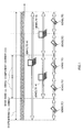
- FIG. 1 is a diagram to show a layered bandwidth configuration defined in LTE-A.
- the example shown in FIG. 1 is a layered bandwidth configuration, in which an LTE-A system having a first system band formed with a plurality of fundamental frequency blocks (hereinafter referred to as "component carriers"), and an LTE system having a second system band formed with one component carrier, coexist.
- component carriers fundamental frequency blocks
- radio communication is performed in a variable system bandwidth of 100 MHz or below
- radio communication is performed in a variable system bandwidth of 20 MHz or below.
- the system band of the LTE-A system includes at least one component carrier, where the system band of the LTE system is one unit. Widening the band by way of gathering a plurality of component carriers in this way is referred to as "carrier aggregation.”
- mobile terminal apparatus UE (User Equipment) #1 is a mobile terminal apparatus to support the LTE-A system (and also support the LTE system), and is able to support a system band up to 100 MHz.
- UE #3 is a mobile terminal apparatus to support the LTE system (and not support the LTE-A system), and is able to support a system band up to 20 MHz (base band).
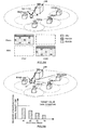
- FIG. 2 provides diagrams to show examples of carrier aggregation in a HetNet.
- the system shown in FIG. 2A is formed in layers with a base station apparatus eNB (eNodeB) and a plurality of base station apparatuses RRH (Remote Radio Head).
- a base station apparatus eNB eNodeB
- RRH Remote Radio Head
- small cells are formed by the base station apparatuses RRH in a localized manner.
- a mobile terminal apparatus UE is located in the small cell of base station apparatus RRH #1, and communicates with the base station apparatus eNB and base station apparatus RRH #1 through carrier aggregation.
- carrier aggregation is executed using component carrier CC #1 of the base station apparatus eNB as a P-cell, and using component carrier CC #2 of base station apparatus RRH #1 as an S-cell.
- a mobile terminal apparatus UE needs to discover (detect) base station apparatuses RRH (S-cells) through inter-frequency measurement, while being connected with the base station apparatus eNB.
- RRH base station apparatuses
- eNB base station apparatuses
- PSS/SSS Primary Synchronization Signal/Secondary Synchronization Signal
- CRSs Cell-specific Reference Signals
- the measured signal quality from each base station apparatus RRH and a predetermined target value are compared, and a base station apparatus RRH (S-cell) of good received quality is detected.
- the synchronization signals cause significant interference and the CRSs are received in insufficient density, and therefore the measurement takes a long time.
- FIG. 3 is a diagram to explain the detection area where base station apparatuses RRH can be detected.
- the target value is low, it is possible to secure a wide detection area and detect base station apparatuses RRH over a wide range.
- SIR Signal to Interference Ratio
- the measurement effort and the measurement time in the mobile terminal apparatus UE increase, and the power consumption of the mobile terminal apparatus UE becomes high.
- the target value is high, the measurement effort is lightened by improvement of the SIR, and the power consumption of the mobile terminal apparatus UE is kept low.
- the detection area becomes narrow, and it becomes difficult to detect base station apparatuses RRH.
- a carrier without compatibility with existing component carriers of carrier aggregation is under study, and this is effective in a HetNet where carrier aggregation is applied.
- the carrier without compatibility with existing component carriers may be referred to as an "additional carrier type" or may be referred to as an “extension carrier.”
- FIG. 4 is a diagram to show an example of carrier aggregation using the additional carrier type. Note that, in FIG. 4 , CC #1 of the base station apparatus eNB is set in the legacy carrier type, and CC #2 of a base station apparatus RRH is set in the additional carrier type. Note that FIG. 4 only shows CRSs (Cell-specific Reference Signals), a PDCCH (Physical Downlink Control Channel), and a PDSCH (Physical Downlink Shared Channel), for ease of explanation.
- CRSs Cell-specific Reference Signals
- PDCCH Physical Downlink Control Channel
- PDSCH Physical Downlink Shared Channel
- a PDCCH is set over three symbols from the top of one resource block defined in LTE.
- CRSs are set not to overlap with user data and other reference signals such as DM-RSs (Demodulation - Reference Signals).
- the CRSs are used to demodulate user data, and, besides, used to measure downlink channel quality (CQI: Channel Quality Indicator) for scheduling and adaptive control, and used to measure an average downlink propagation path state for a cell search and handover (mobility measurement).
- CQI Channel Quality Indicator
- the PDCCH and CRSs can be made subject to "non-transmission.”
- This additional carrier type is not supported by legacy mobile terminal apparatuses (Rel-10 and earlier versions), and is supported only by new mobile terminal apparatuses UE (Rel-11 and later versions).
- the additional carrier type can make downlink control channels (PHICH and PCFICH) subject to non-transmission and make broadcast information (PBCH, Rel-8 SIB, and paging) subject to non-transmission as well.
- PBCH, Rel-8 SIB, and paging broadcast information
- the additional carrier type is presumed to be used primarily in S-cells (secondary cells).
- DM-RSs for data demodulation
- CSI-RSs Channel State Information-Reference Signals
- FDM-type PDCCH uses a predetermined frequency band of the PDSCH region for downlink data signals as an extended PDCCH region.
- the FDM-type PDCCH allocated to this extended PDCCH region is demodulated using DM-RSs.
- an extended PDCCH may be referred to as a "UE-PDCCH.”
- Cross-carrier scheduling refers to the method of transmitting the downlink control channel for the subject carrier using a different carrier. For example, instead of transmitting a downlink control channel using a carrier of the additional carrier type, the downlink control channel may be transmitted using a carrier of the legacy carrier type.
- the additional carrier type makes the PHICH (Physical Hybrid-ARQ Indicator Channel) subject to non-transmission
- retransmission control may be executed based on downlink control information (DCI).
- DCI downlink control information
- the additional carrier type makes the PCFICH (Physical Control Format Indicator Channel) subject to non-transmission
- the number of OFDM symbols to use for the PDCCH may be reported through higher layer signaling.
- the additional carrier type makes broadcast information subject to non-transmission, the broadcast information may be transmitted from a carrier of the legacy carrier type.
- the additional carrier type it is equally possible to provide a configuration not to transmit at least one of CRSs and downlink control channels.
- the bandwidth of the additional carrier type does not have to use the system band (base band: 20 MHz) of the LTE system as one unit, and can be changed as appropriate.
- the present system interference due to CRSs is reduced by executing carrier aggregation using the legacy carrier type and the additional carrier type. That is, the additional carrier type can make CRSs subject to non-transmission, so that interference caused by CRSs from neighboring base station apparatuses RRH can be reduced. Also, by providing a configuration to transmit downlink data in resources for the CRS and the PDCCH, it is possible to improve spectral efficiency.
- a gist of the present invention is to detect S-cells using signals (hereinafter referred to as "carrier detection signals") that are arranged with a high density in a carrier of an additional carrier type instead of the configuration to detect S-cells using a PSS/SSS and CRSs.
- carrier detection signals signals that are arranged with a high density in a carrier of an additional carrier type instead of the configuration to detect S-cells using a PSS/SSS and CRSs.
- the carrier detection signal may be any signal that can be used to detect S-cells, and may be referred to as, for example, DS (Discovery Signal), PDCH (Physical Discovery Channel), BS (Beacon Signal), DPS (Discovery Pilot Signal) and so on.
- DS Discovery Signal
- PDCH Physical Discovery Channel
- BS Beacon Signal
- DPS Discovery Pilot Signal
- This carrier detection signal should preferably have functions for executing long-cycle transmission, high-density transmission, providing orthogonality between cells, securing the number of sequences, providing a sequence that is adequate for generating delay profiles, and so on.
- Long-cycle transmission can reduce the opportunities for measurement by a mobile terminal apparatus by transmitting carrier detection signals once every several seconds in a concentrated manner, and reduce the power consumption of the mobile terminal apparatus.
- High-density transmission can improve received quality in the mobile terminal apparatus by allocating carrier detection signals to one subframe or to a number of consecutive subframes with a high density. By improving received quality, it is possible to shorten the measurement time by the mobile terminal apparatus and reduce the power consumption.
- Orthogonality between cells can improve the received SIR, thereby shortening the time of measurement by a mobile terminal apparatus in a low SIR environment and reducing the power consumption.
- the number of carrier detection signal sequences should preferably be, for example, 504, which is the same as the number of cell IDs, or greater. Furthermore, a sequence that is adequate for generating delay profiles can be realized by allocating carrier detection signals to each subcarrier evenly. Note that the carrier detection signal does not have to have all the functions noted above, and has only to be transmitted with a high density, at least.
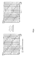
- FIG. 5 is a diagram to explain the PRSs.
- a PRS is a reference signal to be used to measure position of a mobile terminal apparatus.
- PRSs are allocated to spread in the frequency direction and in the time axis direction.
- One resource block is formed with twelve subcarriers that are consecutive in the frequency direction and fourteen symbols that are consecutive in the time axis direction.
- PRSs are allocated to resource blocks to avoid the top three symbols for the PDCCH, namely symbols #0 to #2, and symbols #0, #4, #7 and #11 for CRSs. In each symbol avoiding the PDCCH and CRSs, the PRSs are allocated to two resource elements that are six subcarriers apart.
- the PRSs are shifted in the frequency direction on a per cell basis, so that interference between neighboring cells is reduced.
- PRSs are allocated at six-subcarrier intervals, so that maximum six orthogonal patterns can be defined.
- the system band, the transmission cycle, and the number of consecutive subframes can be set as parameters in higher layers.
- the transmission cycle can be set to 160 msec, 320 msec, 640 msec, and 1280 msec.
- maximum six consecutive subframes can be transmitted.
- PRSs satisfy most of the above-noted functions that are required of the carrier detection signal. Consequently, it is equally possible to use PRSs as a carrier detection signal for S-cell detection.
- the transmission cycle should preferably have options of longer cycles.
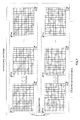
- FIG. 6 is a diagram to show an example of a first signal configuration of the carrier detection signal.
- FIG. 7 is a diagram to show an example of a second signal configuration of the carrier detection signal.
- FIG. 8 is a diagram to show an example of a third signal configuration of the carrier detection signal.
- FIG. 9 is a diagram to show an example of a fourth signal configuration of the carrier detection signal.
- the allocation pattern of the carrier detection signal is defined to maintain the arrangement configuration of the PRS.
- the PDCCH and CRS can be made subject to non-transmission. Consequently, it is possible to allocate the carrier detection signal to the resources of the PDCCH and CRSs (symbols #0 to #2, #4, #7 and #11).
- the carrier detection signal is allocated to two resource elements that are six subcarriers apart, in an arrangement configuration in accordance with the PRS arrangement configuration.
- the carrier detection signal by allocating the carrier detection signal to six orthogonal patterns, six orthogonal sequences are generated. Furthermore, similar to the PRS, it is possible to support long-cycle transmission and high-density transmission by setting the parameters of the transmission cycle and the number of consecutive subframes with higher layers. Also, since the carrier detection signal is allocated to all subcarriers in one resource block, a sequence that is adequate to generate delay profiles is provided. Note that the first signal configuration has only to allocate carrier detection signals such that the carrier detection signals are distributed in the time axis direction and the frequency direction, and is by no means limited to a configuration to hold the arrangement configuration of the PRS.
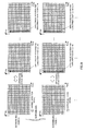
- a plurality of orthogonal patterns are made one group, and a plurality of patterns are generated by randomization between such groups.
- a plurality of mutually varying allocation patterns may be generated by randomizing the subcarriers on a per symbol basis.
- a plurality of groups of orthogonal patterns are defined. Although orthogonality is secured in the groups then, between the groups, part of the resources may become unorthogonal. However, by finding an average of all resources and calculating received quality, it is possible to reduce the influence of interference.
- the second signal configuration compared to the first signal configuration, it is possible to increase the number of sequences by combining shifting in the frequency direction and randomization of allocation patterns. For example, by applying shifts in the frequency direction, six sequences can be generated, so that, if the number of groups is made 84 or more by randomization, it is possible to generate 504 sequences, which is the same number as the number of cell IDs, or generate even more sequences. Also, by setting the parameters of the transmission cycle and the number of consecutive subframes in higher layers in the same way as with the PRS, it is possible to support long-cycle transmission and high-density transmission. Also, since the carrier detection signals are allocated to all subcarriers in one resource block, a sequence that is adequate for generating delay profiles is provided.
- the method of randomizing the allocation patterns is not particularly limited. Also, although the randomized allocation patterns have only to be partly orthogonal at a minimum between the allocation patterns, it is preferable to design the patterns with minimal overlaps. Also, each randomized group may be referred to as a non-orthogonal pattern.
- allocation patterns are defined over a plurality of resource blocks. Consequently, the subcarrier interval between the carrier detection signals in each symbol is defined to be greater than in the allocation pattern of the first signal configuration. For example, an allocation pattern is defined over two resource blocks, and the carrier detection signals are allocated to two resource elements that are fourteen subcarriers apart. Consequently, by shifting the allocation patterns in the frequency direction, fourteen orthogonal patterns can be defined. In this way, with the third signal configuration, it is possible to increase the number of orthogonal patterns (orthogonal sequences) compared to the first and second signal configurations.
- the third signal configuration it is possible to increase the number of sequences by combining shifting in the frequency direction and randomization of allocation patterns. For example, by applying shifts in the frequency direction, fourteen sequences can be generated, so that, if the number of groups is made 36 or more by randomization, it is possible to generate 504 sequences, which is the same number as the number of cell IDs, or generate even more sequences.
- the method of randomizing the allocation patterns is not particularly limited. Also, although the randomized allocation patterns have only to be partly orthogonal at a minimum between the allocation patterns, it is preferable to design the patterns with minimal overlaps. Also, each randomized allocation pattern may be referred to as a non-orthogonal pattern.
- a configuration to generate orthogonal sequences using phase rotation in the frequency direction (cyclic shifts in the time axis direction) is defined.
- the carrier detection signals are allocated over all resource blocks.
- a phase rotation to this signal sequence of the carrier detection signals in the frequency direction on a per subcarrier basis.
- a plurality of orthogonal sequences are generated. For example, by applying phase rotations through M rotations every 2 ⁇ /M, M orthogonal sequences are generated.
- a phase gap of a certain degree or greater needs to be maintained, and the number of sequences that can be generated by phase rotations is limited.
- the number of sequences through phase rotations in the frequency direction and scrambling codes.
- M sequences can be generated through phase rotations in the frequency direction, so that 504/M scrambling codes are necessary.
- the parameters of the transmission cycle and the number of consecutive subframes in higher layers in the same way as with the PRS, it is possible to support long-cycle transmission and high-density transmission.
- the carrier detection signals are allocated to all subcarriers in one resource block, a sequence that is adequate for generating delay profiles is provided. Note that, with the fourth signal configuration, the method of scrambling signal sequences and the method of orthogonalization through cyclic shifts are not particularly limited.
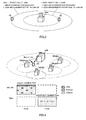
- FIG. 10 is a diagram to explain a system configuration of a radio communication system according to the present embodiment.
- the radio communication system shown in FIG. 10 is a system to accommodate, for example, an LTE system or its successor system.
- carrier aggregation to group a plurality of fundamental frequency blocks into one, where the system band of the LTE system is one unit, is used.
- this radio communication system may be referred to as "IMT-Advanced” or may be referred to as "4G.”
- the radio communication system is a HetNet, and a layered network is built with a base station apparatus (first base station apparatus) 20A of a cell C1, and a plurality of base station apparatuses (second base station apparatuses) 20B of cells C2 that are provided in cell C1.
- the base station apparatus 20A is commonly referred to as a macro base station apparatus, and covers a large-scale cell C1.
- the base station apparatus 20B is commonly referred to as a RRH base station apparatus, and locally forms a small-scale cell C2 in cell C1.
- the base station apparatus 20A and each base station apparatus 20B are connected with each other by wire connection or by wireless connection.
- a mobile terminal apparatus 10 is able to communicate with the base station apparatuses 20A and 20B in cell 1 and in cells 2, respectively.
- the base station apparatus 20A is connected with a core network 30 via a higher station apparatus.
- the higher station apparatus may be, for example, an access gateway apparatus, a radio network controller (RNC), a mobility management entity (MME) and so on, but is by no means limited to these.
- RNC radio network controller
- MME mobility management entity
- the mobile terminal apparatuses 10 include both legacy mobile terminal apparatuses (Rel-10 and earlier versions) and new mobile terminal apparatuses (Rel-11 and later versions), the following description will be given simply with respect to a "mobile terminal apparatus," unless specified otherwise.
- each mobile terminal apparatus 10 will be described to perform radio communication with the base station apparatuses 20A and 20B for ease of explanation, more generally, user equipment (UE) including mobile terminal apparatuses and fixed terminal apparatuses may be used.
- UE user equipment
- This radio communication system supports carrier aggregation specialized for a HetNet.
- a mobile terminal apparatus 10 receives carrier detection signals from each base station apparatus 20B while being connected with the base station apparatus 20A.
- the mobile terminal apparatus 10 measures the signal quality from each base station apparatus 20B based on the carrier detection signals, and feeds back the measurement result to the base station apparatus 20A.
- the base station apparatus 20A detects a base station apparatus 20B of good received quality as an S-cell, and executes carrier aggregation.
- OFDMA Orthogonal Frequency Division Multiple Access
- SC-FDMA Single-Carrier Frequency-Division Multiple Access
- OFDMA is a multi-carrier transmission scheme to perform communication by dividing a frequency band into a plurality of narrow frequency bands (subcarriers) and mapping data to each subcarrier.
- SC-FDMA is a single carrier transmission scheme to reduce interference between terminals by dividing, per terminal, the system band into bands formed with one or continuous resource blocks, and allowing a plurality of terminals to use mutually different bands.
- Downlink communication channels include a PDSCH (Physical Downlink Shared Channel), which is used by each mobile terminal apparatus 10 on a shared basis, and downlink L1/L2 control channels (PDCCH, PCFICH, PHICH).
- PDSCH Physical Downlink Shared Channel
- PCFICH Physical Control Format Indicator Channel
- HARQ ACK and NACK for the PUSCH are transmitted by the PHICH (Physical Hybrid-ARQ Indicator Channel).
- Uplink communication channels include a PUSCH (Physical Uplink Shared Channel), which is an uplink data channel used by each mobile terminal apparatus on a shared basis, and a PUCCH (Physical Uplink Control Channel), which is an uplink control channel. User data and higher control information are transmitted by this PUSCH. Also, downlink radio quality information (CQI: Channel Quality Indicator), ACK/NACK and so on are transmitted by the PUCCH.
- PUSCH Physical Uplink Shared Channel
- PUCCH Physical Uplink Control Channel
- the base station apparatus 20A has a transmitting/receiving antenna 201A, an amplifying section 202A, a transmitting/receiving section 203A, a baseband signal processing section 204A, a call processing section 205A, and a transmission path interface 206A.
- the base station apparatus 20B has a transmitting/receiving antenna 201B, an amplifying section 202B, and a transmitting/receiving section 203B. Transmission data to be transmitted from the base station apparatuses 20A and 20B to the mobile terminal apparatus 10 on the downlink is input from the higher station apparatus into the baseband signal processing section 204A via the transmission path interface 206A.
- a signal of a downlink data channel is subjected to, for example, a PDCP layer process, division and coupling of user data, RLC (Radio Link Control) layer transmission processes such as an RLC retransmission control transmission process, MAC (Medium Access Control) retransmission control, including, for example, an HARQ transmission process, scheduling, transport format selection, channel coding, an inverse fast Fourier transform (IFFT) process, and a precoding process.
- RLC Radio Link Control
- MAC Medium Access Control
- a signal of a downlink control channel is also subjected to transmission processes such as channel coding and an inverse fast Fourier transform.
- the baseband signal processing section 204A reports control information that allows the mobile terminal apparatuses 10 to perform radio communication with the base station apparatuses 20A and 20B, to each mobile terminal apparatus 10 that is connected to the same cell.
- the information to allow communication in the cell includes, for example, the uplink or downlink system bandwidth, identification information of a root sequence (root sequence index) for generating random access preamble signals in the PRACH (Physical Random Access Channel), and so on.
- the baseband signal of CC #1 is output from the baseband signal processing section 204A to the transmitting/receiving section 203A
- the baseband signal of CC #2 is output from the baseband signal processing section 204A to the transmitting/receiving section 203B of the base station apparatus 20B through optical fiber.
- the baseband signals that have been output from the baseband signal processing section 204A are converted into a radio frequency band in the transmitting/receiving sections 203A and 203B.
- the amplifying sections 202A and 202B amplify the radio frequency signals having been subjected to frequency conversion, and the results are transmitted from the transmitting/receiving antennas 201A and 201B.
- radio frequency signals that are received in the transmitting/receiving antennas 201A and 201B of the base station apparatuses 20A and 20B are amplified in the amplifying sections 202A and 202B, converted into baseband signals through frequency conversion in the transmitting/receiving sections 203A and 203B, and input in the baseband signal processing section 204A.
- the baseband signal processing section 204A applies an FFT process, an IDFT process, error correction decoding, a MAC retransmission control receiving process, and RLC layer and PDCP layer receiving processes to the transmission data included in the baseband signals received as input.
- the baseband signals are transferred to the higher station apparatus via the transmission path interface 206A.
- the call processing section 205A performs call processing such as setting up and releasing communication channels, manages the state of the base station apparatuses 20A and 20B, and manages the radio resources.
- the mobile terminal apparatus 10 has a transmitting/receiving antenna 101, an amplifying section 102, a transmitting/receiving section 103 (receiving section), a baseband signal processing section 104, and an application section 105.
- downlink data a radio frequency signal that is received in the transmitting/receiving antenna 101 is amplified in the amplifying section 102, and converted into a baseband signal through frequency conversion in the transmitting/receiving section 103.
- This baseband signal is subjected to receiving processes such as an FFT process, error correction decoding and retransmission control, in the baseband signal processing section 104.
- downlink user data is transferred to the application section 105.
- the application section 105 performs processes related to higher layers above the physical layer and the MAC layer. Also, in the downlink data, broadcast information is also transferred to the application section 105.
- uplink transmission data is input from the application section 105 to the baseband signal processing section 104.
- the baseband signal processing section 104 performs a mapping process, a retransmission control (H-ARQ) transmission process, channel coding, a DFT process, and an IFFT process.
- the baseband signal that is output from the baseband signal processing section 104 is converted into a radio frequency band in the transmitting/receiving section 103, and, after that, amplified in the amplifying section 102 and transmitted from the transmitting/receiving antenna 101.
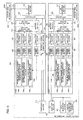
- FIG. 13 is a functional block diagram of a baseband signal processing section 204A provided in the base station apparatus 20A according to the present embodiment and part of the higher layers, and primarily illustrates the function blocks for transmission processes in the baseband signal processing section 204A. Transmission data for the mobile terminal apparatus 10 under the base station apparatus 20A is transferred from the higher station apparatus to the base station apparatus 20A.
- the base station apparatus 20A is shown as an example. Also, a case is shown here where the base station apparatus 20A uses two of CC #1 and CC #2. Obviously, the number of CCs each base station apparatus 20 uses is not limited to this. Also, CC #1 of the base station apparatus 20A is set in the legacy carrier type, and CC #2 is set in the additional carrier type.
- a control information generating section 300 generates, per user, higher control information to report to the mobile terminal apparatus 10 through higher layer signaling.
- the higher control information may include the transmission cycle, the number of consecutive subframes and so on, which are parameters of the carrier detection signal.
- the transmission cycle is set to a long cycle of an interval of several seconds, so as to reduce the opportunities of measurement in the mobile terminal apparatus 10.
- group information and scrambling codes may be included in the higher control information.
- the group information refers to information that represents groups of orthogonal patterns that are grouped by randomization (see FIG. 7 ).
- higher control information for the base station apparatus 20B may furthermore include sequence information representing as to which signal sequences are to be transmitted.
- a control information generating section 300 may apply common group information or scrambling code with respect to each base station apparatus 20B in the same macro cell, and apply varying group information or scrambling codes with respect to base station apparatuses 20B in varying macro cells. By this means, it is possible to allocate orthogonal sequences to each base station apparatus 20B in the same macro cell, and secure orthogonality in the macro cell preferentially.
- a data generating section 301 outputs transmission data transferred from the higher station apparatus as user data, on a per user basis.
- a component carrier selection section 302 selects, on a per mobile terminal apparatus 10, the component carriers to use for radio communication with the mobile terminal apparatus 10.
- CC #1 of the base station apparatus 20A is used as the P-cell, and an S-cell is selected from other base station apparatuses 20B via optical fiber 319.
- An increase/decrease of component carriers is reported from the base station apparatus 20A to the mobile terminal apparatus 10 by higher layer signaling, and a message of completion of application is received from the mobile terminal apparatus 10.
- the scheduling section 310 controls the allocation of component carriers to the subordinate mobile terminal apparatuses 10 according to the overall communication quality of the system band.
- the scheduling section 310 schedules LTE terminal users and LTE-A terminal users separately.
- the scheduling section 310 receives as input data and retransmission commands transmitted from the higher station apparatus, and also receives as input the channel estimation values and resource block CQIs from the receiving section having measured an uplink signal.
- the scheduling section 310 schedules downlink control channel signals and downlink shared channel signals with reference to the retransmission commands, the channel estimation values and the CQIs received as input.
- a propagation path in radio communication varies differently per frequency, due to frequency selective fading. So, the scheduling section 310 designates resource blocks (mapping positions) of good communication quality, on a per subframe basis, with respect to the downlink data for each mobile terminal apparatus 10 (which is referred to as "adaptive frequency scheduling").
- adaptive frequency scheduling for each resource block, a mobile terminal apparatus 10 of good propagation path quality is selected. Consequently, the scheduling section 310 designates resource blocks (mapping positions), using the CQI of each resource block, fed back from each mobile terminal apparatus 10.
- the scheduling section 310 designates resource blocks of good communication quality, on a per subframe basis, with respect to the control information to be transmitted by the PDCCH and so on, by adaptive frequency scheduling. Consequently, the scheduling section 310 designates resource blocks (mapping positions), using the CQI of each resource block, fed back from each mobile terminal apparatus 10. Also, the MCS (coding rate and modulation scheme) that fulfills a predetermined block error rate with the allocated resource blocks is determined. Parameters to fulfill the MCS (coding rate and modulation scheme) determined in the scheduling section 310 are set in channel coding sections 303 and 308, and modulation sections 304 and 309. Note that adaptive frequency scheduling is applied not only to the base station apparatus 20A but is also applied to base station apparatuses 20B via optical fiber 319.
- the baseband signal processing section 204A has channel coding sections 303, modulation sections 304 and mapping sections 305 to support the maximum number of users to multiplex, N, in one component carrier.
- the channel coding sections 303 perform channel coding of the downlink shared data channel (PDSCH), which is formed with downlink data (including part of higher control signals) that is output from the data generating section 301, on a per user basis.
- the modulation sections 304 modulate user data having been subjected to channel coding, on a per user basis.
- the mapping sections 305 map the modulated user data to radio resources.
- the baseband signal processing section 204A has downlink control information generating sections 306 that generate downlink control information, channel coding sections 308 and modulation sections 309.
- downlink control information generating sections 306 uplink shared data channel control information generating sections 306b generate uplink scheduling grants (UL grants) for controlling an uplink data channel (PUSCH).
- the uplink scheduling grants are generated on a per user basis.
- downlink shared data channel control information generating sections 306c generate downlink scheduling assignments (DL assignments) for controlling a downlink data channel (PDSCH). The downlink scheduling assignments are generated on a per user basis. Also, shared channel control information generating sections 306a generate shared control channel control information, which is downlink control information that is common between users.
- the control information that is modulated in the modulation sections 309 on a per user basis is multiplexed in the control channel multiplexing sections 314 and furthermore interleaved in interleaving sections 315.
- a control signal that is output from the interleaving sections 315 and user data that is output from the mapping sections 305 are input in IFFT sections 316 as downlink channel signals.
- the baseband signal processing section 204A (CC #2) for the base station apparatus 20B has a reference signal generating section 318 (generating section) that generates reference signals.
- the reference signal generating section 318 generates carrier detection signals as reference signals based on the uplink control information.
- the reference signal generating section 318 may generate a CRS for channel estimation, a DM-RS for downlink demodulation, and a CSI-RS for CSI measurement.
- Higher control information is reported from the control information generating section 300 to the reference signal generating section 318.
- the transmission cycle of carrier detection signals, the number of consecutive subframes, and sequence information to represent signal sequences are reported as higher control information.
- the amount of shift (V shift ) of carrier detection signals may be reported as sequence information.
- signal sequences that are defined by the amount of shift are used (see FIG. 6 ). Note that, when the amount of shift and cell IDs are associated on a one-by-one basis, it is not necessary to report the amount of shift.
- the transmission cycle of carrier detection signals, the number of consecutive subframes, group information, and sequence information are reported as higher control information.
- the amount of shift (V shift ) of carrier detection signals may be reported as sequence information.
- signal sequences that are defined by group information and the amount of shift are used (see FIGs. 7 and 8 ). Note that ,when the amount of shift and cell IDs are associated on a one-by-one basis, it is not necessary to report the amount of shift.
- the transmission cycle of carrier detection signals, the number of consecutive subframes, scrambling codes and sequence information are reported as higher control information.
- the phase rotation angle may be reported as sequence information.
- phase rotation angle and cell IDs are associated on a one-by-one basis, it is not necessary to report the phase rotation angle.
- a control signal is input from the interleaving sections 315, and user data is input from the mapping sections 305.
- a downlink reference signal is furthermore input from the reference signal generating section 318.
- the IFFT sections 316 perform an inverse fast Fourier transform of the downlink channel signal and the downlink reference signal and converts frequency domain signals into time sequence signals.
- Cyclic prefix insertion sections 317 insert cyclic prefixes in the time sequence signal of the downlink channel signal. Note that a cyclic prefix functions as a guard interval for cancelling the differences in multipath propagation delay. Transmission data, to which cyclic prefixes have been added, is transmitted to the transmitting/receiving sections 203A and 203B.
- FIG. 14 shows a functional block diagram of the baseband signal processing section 104 provided in the mobile terminal apparatus 10, and shows the function blocks of an LTE-A terminal that supports the additional carrier type.
- a downlink signal that is received from the base station apparatuses 20A and 20B as received data has the CPs removed in a CP removing section 401.
- the downlink signal, from which the CPs have been removed, is input in an FFT section 402.
- the FFT section 402 performs a fast Fourier transform (FFT) on the downlink signal, converts the time domain signal into a frequency domain signal and inputs this signal in a demapping section 403.
- the demapping section 403 demaps the downlink signal, and extracts, from the downlink signal, multiplex control information in which a plurality of pieces of control information are multiplexed, user data and higher control signals.
- FFT fast Fourier transform
- the demapping process by the demapping section 403 is performed based on higher control signals that are received as input from the application section 105.
- the multiplex control information that is output from the demapping section 403 is deinterleaved in a deinterleaving section 404.
- the baseband signal processing section 104 has a downlink control information demodulation section 405 that demodulates downlink control information, a data demodulation section 406 that demodulates downlink shared data, a channel estimation section 407, and a received quality measurement section (measurement section) 408.
- the downlink control information demodulation section 405 includes a shared channel control information demodulation section 405a that demodulates shared control channel control information from the multiplexed control information, an uplink shared data channel control information demodulation section 405b that demodulates uplink shared data channel control information from the multiplexed control information, and a downlink shared data channel control information demodulation section 405c that demodulates downlink shared data channel control information from the multiplexed control information.
- the shared channel control information demodulation section 405a extracts shared control channel control information, which is control information that is common between users, by performing a blind decoding process, a demodulation process, a channel decoding process and so on of the common search spaces of the downlink control channel (PDCCH).
- the shared control channel control information includes downlink channel quality information (CQI), and is input in a mapping section 415 and mapped as part of transmission data for the base station apparatus 20.
- CQI downlink channel quality information
- the uplink shared data channel control information demodulation section 405b extracts uplink shared data channel control information (for example, UL grants) by performing a blind decoding process, a demodulation process, a channel decoding process and so on of the user-specific search spaces of the downlink control channel (PDCCH).
- the demodulated uplink shared data channel control information is input in the mapping section 415 and is used to control the uplink shared data channel (PUSCH).
- the downlink shared data channel control information demodulation section 405c extracts user-specific downlink shared data channel control information (for example, DL assignments) by performing a blind decoding process, a demodulation process, a channel decoding process and so on of the user-specific search spaces of the downlink control channel (PDCCH).
- the demodulated downlink shared data channel control information is input in the data demodulation section 406, used to control the downlink shared data channel (PDSCH), and input in a downlink shared data demodulation section 406a.
- the data demodulation section 406 includes the downlink shared data demodulation section 406a that demodulates user data and higher control signals, and a downlink shared channel data demodulation section 406b that demodulates downlink shared channel data.
- the downlink shared data demodulation section 406a acquires user data and higher control information based on the downlink shared data channel control information that is input from the downlink shared data channel control information demodulation section 405c.
- the downlink shared channel data demodulation section 406b demodulates downlink shared channel data based on the uplink shared data channel control information that is input from the uplink shared data channel control information demodulation section 405b.
- the data demodulation section 406 performs derate matching by switching the rate matching pattern depending on the carrier type of component carriers. For example, with component carriers of the additional carrier type, the demodulation process is performed adequately taking into account the user data allocated to the resources of CRSs and the PDCCH.
- the channel estimation section 407 performs channel estimation using user-specific reference signals (DM-RSs) or cell-specific reference signals (CRSs).
- DM-RSs user-specific reference signals
- CRSs cell-specific reference signals
- the channel estimation section 407 outputs the estimated channel variation to the shared channel control information demodulation section 405a, the uplink shared data channel control information demodulation section 405b, the downlink shared data channel control information demodulation section 405c and the downlink shared data demodulation section 406a.
- the demodulation process is performed using the estimated channel variation and reference signals for demodulation.
- the received quality measurement section 408 measures received quality based on the carrier detection signals transmitted in CC #2 of the additional carrier pattern from each base station apparatus 20B. Higher control information is input in the received quality measurement section 408 from the downlink shared data demodulation section 406a. With the first signal configuration, the transmission cycle of carrier detection signals and the number of consecutive subframes are input in the received quality measurement section 408 as higher control information.
- the received quality measurement section 408 measures the orthogonal sequences of all (for example, six) orthogonal patterns at times specified by the transmission cycle and the number of consecutive subframes.
- the transmission cycle of carrier detection signals, the number of consecutive subframes, and group information are input in the received quality measurement section 408 as higher control information.
- the received quality measurement section 408 measures the orthogonal sequences of all orthogonal patterns in the group represented in the group information, at times specified by the transmission cycle and the number of consecutive subframes. Note that a plurality of pieces of group information may be input in the received quality measurement section 408. In this case, the received quality measurement section 408 measures all the orthogonal sequences in a plurality of groups.
- the transmission cycle of carrier detection signals, the number of consecutive subframes and scrambling codes are input in the received quality measurement section 408 as higher control information.
- the received quality measurement section 408 measures all the orthogonal sequences generated by scrambling and phase rotations, at times specified by the transmission cycle and the number of consecutive subframes. Note that a plurality of scrambling codes may be input in the received quality measurement section 408 as well. In this case, the received quality measurement section 408 measures all the orthogonal sequences generated by scrambling and phase rotations by a plurality of scrambling codes.
- sequence information to represent specific signal sequences may be input in the received quality measurement section 408 as higher control information.
- the received quality measurement section 408 does not have to measure all the orthogonal patterns, so that the measurement effort can be lightened.
- the transmission cycle is set to be a long cycle, the opportunities of measurement in the received quality measurement section 408 are reduced, so that it is possible to reduce the power consumption. Also, if consecutive subframes are set, improvement of received quality shortens the measurement time in the received quality measurement section 408, and the power consumption is reduced. Also, since the orthogonality of signal sequences is taken into account, the time of measurement by the received quality measurement section 408 under a low SIR environment becomes shorter, and the power consumption is reduced. Note that when orthogonal sequences are allocated to each base station apparatus 20B in the same macro cell and orthogonal sequences of different groups are allocated between varying macro cells, it may be possible to measure only the orthogonal sequences in the macro cell where the subject apparatus belongs. In this case, common group information and scrambling code are allocated to each base station apparatus 20B in the same macro cell.
- the received quality measurement section 408 outputs the received quality measurement result to the mapping section 415, and sends feedback to the base station apparatus 20A.
- the received quality measurement result may be fed back from the mobile terminal apparatus 10 to the base station apparatus 20A directly, or may be fed back from the mobile terminal apparatus 10 to the base station apparatus 20A via the base station apparatus 20B.
- the variations of orthogonal patterns may be defined in advance, or may be reported to the mobile terminal apparatus 10.
- the phase rotation angle may be defined in advance, or may be reported to the mobile terminal apparatus 10.
- the transmission cycle, the number of consecutive subframes, group information and scrambling codes may be reported through a downlink control channel or a broadcast channel, instead of being reported through higher layer signaling.
- the baseband signal processing section 104 has, as function blocks of the transmission processing system, a data generating section 411, a channel coding section 412, a modulation section 413, a DFT section 414, a mapping section 415, an IFFT section 416, and a CP insertion section 417.
- the data generating section 411 generates transmission data from bit data that is received as input from the application section 105.
- the channel coding section 412 performs a channel coding process such as error correction for the transmission data
- the modulation section 413 modulates the transmission data after the channel coding by QPSK and so on.
- the DFT section 414 performs a discrete Fourier transform on the modulated transmission data.
- the mapping section 415 maps the frequency components of the data symbols after the DFT, to subcarrier positions designated by the base station apparatuses 20A and 20B.
- the IFFT section 416 converts the input data, which corresponds to the system band, into time sequence data by performing an inverse fast Fourier transform, and the CP insertion section 417 inserts cyclic prefixes in the time sequence data in data units.
- the received quality measurement results of signal sequences from the base station apparatuses 20B and the target value are compared, and the measurement results of base station apparatuses 20B (S-cells) where signal sequences of good received quality are allocated are fed back. Then, based on the measurement results fed back, the base station apparatus 20A executes carrier aggregation between the base station apparatus 20A and the detected (discovered) base station apparatuses 20B.
- the communication system it is possible to make CRSs and the PDCCH subject to non-transmission in an additional carrier pattern, so that it is possible to transmit carrier detection signals from a base station apparatus 20B to a mobile terminal apparatus 10 with a high density. Consequently, in the mobile terminal apparatus 10, the signal quality from the base station apparatus 20B measured with the carrier detection signals improves, and the effort of the mobile terminal apparatus 10 for measuring received quality is lightened. Consequently, the mobile terminal apparatus 10 is able to detect an S-cell in a short time and reduce the power consumption.
- the present invention is by no means limited to the above embodiments and can be implemented in various modifications.
- it is possible to adequately change the number of carriers, the bandwidth of carriers, the signaling method, the type of the additional carrier type, the number of processing sections, the order of processing steps in the above description, and implement the present invention.
- the present invention can be implemented with various changes, without departing from the scope of the present invention.
Landscapes
- Engineering & Computer Science (AREA)
- Signal Processing (AREA)
- Computer Networks & Wireless Communication (AREA)
- Databases & Information Systems (AREA)
- Mobile Radio Communication Systems (AREA)
Applications Claiming Priority (2)
| Application Number | Priority Date | Filing Date | Title |
|---|---|---|---|
| JP2012017358A JP5827899B2 (ja) | 2012-01-30 | 2012-01-30 | 通信システム、基地局装置、移動端末装置及び通信方法 |
| PCT/JP2013/052063 WO2013115259A1 (fr) | 2012-01-30 | 2013-01-30 | Système de communication, dispositif station de base, dispositif terminal mobile et procédé de communication |
Publications (3)
| Publication Number | Publication Date |
|---|---|
| EP2811797A1 true EP2811797A1 (fr) | 2014-12-10 |
| EP2811797A4 EP2811797A4 (fr) | 2015-08-19 |
| EP2811797B1 EP2811797B1 (fr) | 2016-07-27 |
Family
ID=48905291
Family Applications (1)
| Application Number | Title | Priority Date | Filing Date |
|---|---|---|---|
| EP13742921.3A Not-in-force EP2811797B1 (fr) | 2012-01-30 | 2013-01-30 | Dispositif station de base, dispositif terminal mobile et procédé de communication |
Country Status (5)
| Country | Link |
|---|---|
| US (1) | US9419771B2 (fr) |
| EP (1) | EP2811797B1 (fr) |
| JP (1) | JP5827899B2 (fr) |
| CN (2) | CN104106297A (fr) |
| WO (1) | WO2013115259A1 (fr) |
Cited By (1)
| Publication number | Priority date | Publication date | Assignee | Title |
|---|---|---|---|---|
| WO2015114566A1 (fr) * | 2014-01-30 | 2015-08-06 | Telefonaktiebolaget L M Ericsson (Publ) | Signaux et procédures de découverte |
Families Citing this family (12)
| Publication number | Priority date | Publication date | Assignee | Title |
|---|---|---|---|---|
| KR20090006708A (ko) * | 2007-07-12 | 2009-01-15 | 엘지전자 주식회사 | 스케줄링 요청 신호 전송 방법 |
| US9198066B2 (en) * | 2012-02-29 | 2015-11-24 | Panasonic Intellectual Property Corporation Of America | Wireless communication device, wireless communication terminal, reference signal transmission control method, and reference signal processing method |
| EP2904864B1 (fr) | 2012-10-05 | 2019-09-18 | Sierra Wireless, Inc. | Procédé et système d'allocation de ressource radio en liaison montante dans un système de communication lte |
| CN104838715A (zh) | 2012-10-05 | 2015-08-12 | 司亚乐无线通讯股份有限公司 | 用于无线电资源分配的方法和系统 |
| WO2014179874A1 (fr) * | 2013-05-10 | 2014-11-13 | Sierra Wireless, Inc. | Procédé et appareil de communication d'informations système dans un système sans fil |
| JP6301082B2 (ja) * | 2013-07-30 | 2018-03-28 | 株式会社Kddi総合研究所 | 通信装置並びにその制御方法、基地局装置並びにその制御方法、及びプログラム |
| JP5984769B2 (ja) * | 2013-09-26 | 2016-09-06 | 株式会社Nttドコモ | ユーザ端末、無線基地局及び無線通信方法 |
| JP6359815B2 (ja) * | 2013-09-26 | 2018-07-18 | 株式会社Nttドコモ | ユーザ端末、無線基地局及び異周波測定方法 |
| WO2017003325A1 (fr) * | 2015-06-28 | 2017-01-05 | Telefonaktiebolaget Lm Ericsson (Publ) | Détermination de la position d'un dispositif sans fil par l'utilisation de têtes radio distantes |
| US10904729B2 (en) * | 2016-12-20 | 2021-01-26 | Verizon Patent And Licensing Inc. | System and method for improved capacity using channel multiplexing |
| US10778384B2 (en) | 2016-12-20 | 2020-09-15 | Verizon Patent And Licensing Inc. | System and method for improved capacity using channel multiplexing |
| KR102392079B1 (ko) * | 2018-05-04 | 2022-05-02 | 주식회사 케이티 | 차세대 무선망에서 포지셔닝을 수행하는 방법 및 장치 |
Family Cites Families (18)
| Publication number | Priority date | Publication date | Assignee | Title |
|---|---|---|---|---|
| US7092353B2 (en) * | 2003-10-17 | 2006-08-15 | Qualcomm Incorporated | Carrier search methods and apparatus |
| JP4958565B2 (ja) * | 2006-01-06 | 2012-06-20 | パナソニック株式会社 | 無線通信装置 |
| CN102090012B (zh) * | 2008-05-09 | 2016-06-08 | 诺基亚通信公司 | 基于3g-lte的虚拟导频序列中的多小区信道估计 |
| US10218481B2 (en) * | 2009-04-22 | 2019-02-26 | Lg Electronics Inc. | Apparatus and method for transmitting a reference signal in a wireless communication system |
| WO2010140859A2 (fr) * | 2009-06-03 | 2010-12-09 | 엘지전자 주식회사 | Procédé et appareil pour émettre un signal de référence de sondage |
| CN101932045B (zh) * | 2009-06-24 | 2014-11-05 | 中兴通讯股份有限公司 | 载波聚合中测量结果的上报方法及用户设备 |
| CN101615984B (zh) * | 2009-08-07 | 2013-03-27 | 中兴通讯股份有限公司 | 载波聚合下周期性cqi反馈的方法和装置 |
| AU2010290233B2 (en) * | 2009-09-07 | 2014-08-28 | Lg Electronics Inc. | Method and apparatus for transmitting/receiving a reference signal in a wireless communication system |
| WO2011103186A2 (fr) * | 2010-02-16 | 2011-08-25 | Zte (Usa) Inc. | Procédés et appareils pour des économies d'énergie de réseau dans un système de communication sans fil |
| US8818399B2 (en) * | 2010-02-25 | 2014-08-26 | Telefonaktiebolaget L M Ericsson (Publ) | Methods and nodes in a wireless communication network |
| US8897228B2 (en) * | 2010-04-26 | 2014-11-25 | Sharp Kabushiki Kaisha | Mobile communication system, base station apparatus, mobile station apparatus and communication method |
| CN101860396B (zh) * | 2010-06-12 | 2016-04-13 | 中兴通讯股份有限公司 | 控制格式指示值的传输方法 |
| CN102281556A (zh) * | 2010-06-13 | 2011-12-14 | 中兴通讯股份有限公司 | 多载波通信系统以及载波聚合中启动测量任务的方法 |
| PL2586137T3 (pl) * | 2010-06-23 | 2017-09-29 | Telefonaktiebolaget Lm Ericsson (Publ) | Zarządzanie interferencjami sygnałów referencyjnych w sieciach heterogenicznych |
| US9402264B2 (en) * | 2011-09-30 | 2016-07-26 | Intel Corporation | Methods to transport internet traffic over multiple wireless networks simultaneously |
| JP5703398B2 (ja) * | 2011-10-18 | 2015-04-15 | エルジー エレクトロニクス インコーポレイティド | 制御チャネルを復調するためのプライマリセル指示方法及び装置 |
| US20150043520A1 (en) * | 2011-11-17 | 2015-02-12 | Broadcom Corporation | Methods and Apparatuses for Provision of Reference Signal Design for Downlink Tracking in Occupied Shared Band |
| US8885569B2 (en) * | 2011-12-19 | 2014-11-11 | Ofinno Technologies, Llc | Beamforming signaling in a wireless network |
-
2012
- 2012-01-30 JP JP2012017358A patent/JP5827899B2/ja not_active Expired - Fee Related
-
2013
- 2013-01-30 EP EP13742921.3A patent/EP2811797B1/fr not_active Not-in-force
- 2013-01-30 US US14/374,966 patent/US9419771B2/en not_active Expired - Fee Related
- 2013-01-30 CN CN201380007340.0A patent/CN104106297A/zh active Pending
- 2013-01-30 WO PCT/JP2013/052063 patent/WO2013115259A1/fr active Application Filing
- 2013-01-30 CN CN201810534302.5A patent/CN108650052B/zh active Active
Cited By (5)
| Publication number | Priority date | Publication date | Assignee | Title |
|---|---|---|---|---|
| WO2015114566A1 (fr) * | 2014-01-30 | 2015-08-06 | Telefonaktiebolaget L M Ericsson (Publ) | Signaux et procédures de découverte |
| US10091774B2 (en) | 2014-01-30 | 2018-10-02 | Telefonaktiebolaget Lm Ericsson (Publ) | Discovery signals and procedures |
| EP3780749A1 (fr) * | 2014-01-30 | 2021-02-17 | Telefonaktiebolaget LM Ericsson (publ) | Signaux et procédures de découverte |
| USRE49397E1 (en) | 2014-01-30 | 2023-01-24 | Telefonaktiebolaget Lm Ericsson (Publ) | Discovery signals and procedures |
| EP4192116A1 (fr) * | 2014-01-30 | 2023-06-07 | Telefonaktiebolaget LM Ericsson (publ) | Signaux et procédures de découverte |
Also Published As
| Publication number | Publication date |
|---|---|
| EP2811797A4 (fr) | 2015-08-19 |
| US9419771B2 (en) | 2016-08-16 |
| US20140369223A1 (en) | 2014-12-18 |
| CN108650052A (zh) | 2018-10-12 |
| EP2811797B1 (fr) | 2016-07-27 |
| CN108650052B (zh) | 2021-09-28 |
| JP2013157823A (ja) | 2013-08-15 |
| JP5827899B2 (ja) | 2015-12-02 |
| CN104106297A (zh) | 2014-10-15 |
| WO2013115259A1 (fr) | 2013-08-08 |
Similar Documents
| Publication | Publication Date | Title |
|---|---|---|
| EP2811797B1 (fr) | Dispositif station de base, dispositif terminal mobile et procédé de communication | |
| US9756633B2 (en) | Radio base station apparatus, mobile terminal apparatus, radio communication system and radio communication method | |
| EP2830375B1 (fr) | Système de communication, dispositif formant terminal mobile et procédé de communication | |
| US9380570B2 (en) | Radio base station apparatus, user terminal, radio communication system and radio communication method | |
| EP2811799A1 (fr) | Dispositif station de base sans fil, terminal utilisateur, système de communication sans fil et procédé de communication sans fil | |
| EP2919526B1 (fr) | Méthode de radio communication, système de radio communication, station de base radio et terminal utilisateur | |
| US9467989B2 (en) | Base station apparatus, mobile terminal apparatus, communication system and communication method | |
| EP2930990B1 (fr) | Station de base sans fil, terminal d'utilisateur, et procédé de communication sans fil | |
| US9716578B2 (en) | User terminal, radio base station apparatus, radio communication system and radio communication method | |
| US9313014B2 (en) | Radio communication system, radio communication method, radio base station apparatus and user terminal | |
| US20140192758A1 (en) | Communication system, base station apparatus, mobile terminal apparatus and communication method | |
| EP2836001A1 (fr) | Système de communication, dispositif formant station de base, et procédé de communication |
Legal Events
| Date | Code | Title | Description |
|---|---|---|---|
| PUAI | Public reference made under article 153(3) epc to a published international application that has entered the european phase |
Free format text: ORIGINAL CODE: 0009012 |
|
| 17P | Request for examination filed |
Effective date: 20140811 |
|
| AK | Designated contracting states |
Kind code of ref document: A1 Designated state(s): AL AT BE BG CH CY CZ DE DK EE ES FI FR GB GR HR HU IE IS IT LI LT LU LV MC MK MT NL NO PL PT RO RS SE SI SK SM TR |
|
| AX | Request for extension of the european patent |
Extension state: BA ME |
|
| DAX | Request for extension of the european patent (deleted) | ||
| RA4 | Supplementary search report drawn up and despatched (corrected) |
Effective date: 20150722 |
|
| RIC1 | Information provided on ipc code assigned before grant |
Ipc: H04J 11/00 20060101ALI20150716BHEP Ipc: H04W 36/00 20090101ALI20150716BHEP Ipc: H04W 16/32 20090101ALI20150716BHEP Ipc: H04L 5/00 20060101ALI20150716BHEP Ipc: H04W 72/04 20090101AFI20150716BHEP |
|
| GRAP | Despatch of communication of intention to grant a patent |
Free format text: ORIGINAL CODE: EPIDOSNIGR1 |
|
| RIC1 | Information provided on ipc code assigned before grant |
Ipc: H04W 36/00 20090101ALI20160203BHEP Ipc: H04W 88/02 20090101ALN20160203BHEP Ipc: H04J 11/00 20060101ALI20160203BHEP Ipc: H04L 5/00 20060101ALI20160203BHEP Ipc: H04W 72/04 20090101AFI20160203BHEP Ipc: H04W 16/32 20090101ALI20160203BHEP |
|
| INTG | Intention to grant announced |
Effective date: 20160217 |
|
| GRAS | Grant fee paid |
Free format text: ORIGINAL CODE: EPIDOSNIGR3 |
|
| GRAA | (expected) grant |
Free format text: ORIGINAL CODE: 0009210 |
|
| AK | Designated contracting states |
Kind code of ref document: B1 Designated state(s): AL AT BE BG CH CY CZ DE DK EE ES FI FR GB GR HR HU IE IS IT LI LT LU LV MC MK MT NL NO PL PT RO RS SE SI SK SM TR |
|
| REG | Reference to a national code |
Ref country code: GB Ref legal event code: FG4D |
|
| REG | Reference to a national code |
Ref country code: CH Ref legal event code: EP |
|
| REG | Reference to a national code |
Ref country code: AT Ref legal event code: REF Ref document number: 816696 Country of ref document: AT Kind code of ref document: T Effective date: 20160815 |
|
| REG | Reference to a national code |
Ref country code: IE Ref legal event code: FG4D |
|
| REG | Reference to a national code |
Ref country code: DE Ref legal event code: R096 Ref document number: 602013009904 Country of ref document: DE |
|
| REG | Reference to a national code |
Ref country code: LT Ref legal event code: MG4D |
|
| REG | Reference to a national code |
Ref country code: NL Ref legal event code: MP Effective date: 20160727 |
|
| REG | Reference to a national code |
Ref country code: AT Ref legal event code: MK05 Ref document number: 816696 Country of ref document: AT Kind code of ref document: T Effective date: 20160727 |
|
| PG25 | Lapsed in a contracting state [announced via postgrant information from national office to epo] |
Ref country code: LT Free format text: LAPSE BECAUSE OF FAILURE TO SUBMIT A TRANSLATION OF THE DESCRIPTION OR TO PAY THE FEE WITHIN THE PRESCRIBED TIME-LIMIT Effective date: 20160727 Ref country code: FI Free format text: LAPSE BECAUSE OF FAILURE TO SUBMIT A TRANSLATION OF THE DESCRIPTION OR TO PAY THE FEE WITHIN THE PRESCRIBED TIME-LIMIT Effective date: 20160727 Ref country code: IT Free format text: LAPSE BECAUSE OF FAILURE TO SUBMIT A TRANSLATION OF THE DESCRIPTION OR TO PAY THE FEE WITHIN THE PRESCRIBED TIME-LIMIT Effective date: 20160727 Ref country code: IS Free format text: LAPSE BECAUSE OF FAILURE TO SUBMIT A TRANSLATION OF THE DESCRIPTION OR TO PAY THE FEE WITHIN THE PRESCRIBED TIME-LIMIT Effective date: 20161127 Ref country code: RS Free format text: LAPSE BECAUSE OF FAILURE TO SUBMIT A TRANSLATION OF THE DESCRIPTION OR TO PAY THE FEE WITHIN THE PRESCRIBED TIME-LIMIT Effective date: 20160727 Ref country code: HR Free format text: LAPSE BECAUSE OF FAILURE TO SUBMIT A TRANSLATION OF THE DESCRIPTION OR TO PAY THE FEE WITHIN THE PRESCRIBED TIME-LIMIT Effective date: 20160727 Ref country code: NO Free format text: LAPSE BECAUSE OF FAILURE TO SUBMIT A TRANSLATION OF THE DESCRIPTION OR TO PAY THE FEE WITHIN THE PRESCRIBED TIME-LIMIT Effective date: 20161027 Ref country code: NL Free format text: LAPSE BECAUSE OF FAILURE TO SUBMIT A TRANSLATION OF THE DESCRIPTION OR TO PAY THE FEE WITHIN THE PRESCRIBED TIME-LIMIT Effective date: 20160727 |
|
| PG25 | Lapsed in a contracting state [announced via postgrant information from national office to epo] |
Ref country code: ES Free format text: LAPSE BECAUSE OF FAILURE TO SUBMIT A TRANSLATION OF THE DESCRIPTION OR TO PAY THE FEE WITHIN THE PRESCRIBED TIME-LIMIT Effective date: 20160727 Ref country code: PT Free format text: LAPSE BECAUSE OF FAILURE TO SUBMIT A TRANSLATION OF THE DESCRIPTION OR TO PAY THE FEE WITHIN THE PRESCRIBED TIME-LIMIT Effective date: 20161128 Ref country code: LV Free format text: LAPSE BECAUSE OF FAILURE TO SUBMIT A TRANSLATION OF THE DESCRIPTION OR TO PAY THE FEE WITHIN THE PRESCRIBED TIME-LIMIT Effective date: 20160727 Ref country code: AT Free format text: LAPSE BECAUSE OF FAILURE TO SUBMIT A TRANSLATION OF THE DESCRIPTION OR TO PAY THE FEE WITHIN THE PRESCRIBED TIME-LIMIT Effective date: 20160727 Ref country code: PL Free format text: LAPSE BECAUSE OF FAILURE TO SUBMIT A TRANSLATION OF THE DESCRIPTION OR TO PAY THE FEE WITHIN THE PRESCRIBED TIME-LIMIT Effective date: 20160727 Ref country code: SE Free format text: LAPSE BECAUSE OF FAILURE TO SUBMIT A TRANSLATION OF THE DESCRIPTION OR TO PAY THE FEE WITHIN THE PRESCRIBED TIME-LIMIT Effective date: 20160727 Ref country code: BE Free format text: LAPSE BECAUSE OF FAILURE TO SUBMIT A TRANSLATION OF THE DESCRIPTION OR TO PAY THE FEE WITHIN THE PRESCRIBED TIME-LIMIT Effective date: 20160727 Ref country code: GR Free format text: LAPSE BECAUSE OF FAILURE TO SUBMIT A TRANSLATION OF THE DESCRIPTION OR TO PAY THE FEE WITHIN THE PRESCRIBED TIME-LIMIT Effective date: 20161028 |
|
| PG25 | Lapsed in a contracting state [announced via postgrant information from national office to epo] |
Ref country code: EE Free format text: LAPSE BECAUSE OF FAILURE TO SUBMIT A TRANSLATION OF THE DESCRIPTION OR TO PAY THE FEE WITHIN THE PRESCRIBED TIME-LIMIT Effective date: 20160727 Ref country code: RO Free format text: LAPSE BECAUSE OF FAILURE TO SUBMIT A TRANSLATION OF THE DESCRIPTION OR TO PAY THE FEE WITHIN THE PRESCRIBED TIME-LIMIT Effective date: 20160727 |
|
| REG | Reference to a national code |
Ref country code: DE Ref legal event code: R097 Ref document number: 602013009904 Country of ref document: DE |
|
| PG25 | Lapsed in a contracting state [announced via postgrant information from national office to epo] |
Ref country code: CZ Free format text: LAPSE BECAUSE OF FAILURE TO SUBMIT A TRANSLATION OF THE DESCRIPTION OR TO PAY THE FEE WITHIN THE PRESCRIBED TIME-LIMIT Effective date: 20160727 Ref country code: SK Free format text: LAPSE BECAUSE OF FAILURE TO SUBMIT A TRANSLATION OF THE DESCRIPTION OR TO PAY THE FEE WITHIN THE PRESCRIBED TIME-LIMIT Effective date: 20160727 Ref country code: BG Free format text: LAPSE BECAUSE OF FAILURE TO SUBMIT A TRANSLATION OF THE DESCRIPTION OR TO PAY THE FEE WITHIN THE PRESCRIBED TIME-LIMIT Effective date: 20161027 Ref country code: SM Free format text: LAPSE BECAUSE OF FAILURE TO SUBMIT A TRANSLATION OF THE DESCRIPTION OR TO PAY THE FEE WITHIN THE PRESCRIBED TIME-LIMIT Effective date: 20160727 Ref country code: DK Free format text: LAPSE BECAUSE OF FAILURE TO SUBMIT A TRANSLATION OF THE DESCRIPTION OR TO PAY THE FEE WITHIN THE PRESCRIBED TIME-LIMIT Effective date: 20160727 |
|
| PLBE | No opposition filed within time limit |
Free format text: ORIGINAL CODE: 0009261 |
|
| STAA | Information on the status of an ep patent application or granted ep patent |
Free format text: STATUS: NO OPPOSITION FILED WITHIN TIME LIMIT |
|
| 26N | No opposition filed |
Effective date: 20170502 |
|
| REG | Reference to a national code |
Ref country code: DE Ref legal event code: R119 Ref document number: 602013009904 Country of ref document: DE |
|
| PG25 | Lapsed in a contracting state [announced via postgrant information from national office to epo] |
Ref country code: SI Free format text: LAPSE BECAUSE OF FAILURE TO SUBMIT A TRANSLATION OF THE DESCRIPTION OR TO PAY THE FEE WITHIN THE PRESCRIBED TIME-LIMIT Effective date: 20160727 |
|
| REG | Reference to a national code |
Ref country code: CH Ref legal event code: PL |
|
| PG25 | Lapsed in a contracting state [announced via postgrant information from national office to epo] |
Ref country code: MC Free format text: LAPSE BECAUSE OF FAILURE TO SUBMIT A TRANSLATION OF THE DESCRIPTION OR TO PAY THE FEE WITHIN THE PRESCRIBED TIME-LIMIT Effective date: 20160727 |
|
| REG | Reference to a national code |
Ref country code: FR Ref legal event code: ST Effective date: 20170929 |
|
| PG25 | Lapsed in a contracting state [announced via postgrant information from national office to epo] |
Ref country code: LI Free format text: LAPSE BECAUSE OF NON-PAYMENT OF DUE FEES Effective date: 20170131 Ref country code: CH Free format text: LAPSE BECAUSE OF NON-PAYMENT OF DUE FEES Effective date: 20170131 Ref country code: FR Free format text: LAPSE BECAUSE OF NON-PAYMENT OF DUE FEES Effective date: 20170131 |
|
| REG | Reference to a national code |
Ref country code: IE Ref legal event code: MM4A |
|
| PG25 | Lapsed in a contracting state [announced via postgrant information from national office to epo] |
Ref country code: LU Free format text: LAPSE BECAUSE OF NON-PAYMENT OF DUE FEES Effective date: 20170130 Ref country code: DE Free format text: LAPSE BECAUSE OF NON-PAYMENT OF DUE FEES Effective date: 20170801 |
|
| PG25 | Lapsed in a contracting state [announced via postgrant information from national office to epo] |
Ref country code: IE Free format text: LAPSE BECAUSE OF NON-PAYMENT OF DUE FEES Effective date: 20170130 |
|
| PGFP | Annual fee paid to national office [announced via postgrant information from national office to epo] |
Ref country code: GB Payment date: 20180124 Year of fee payment: 6 |
|
| PG25 | Lapsed in a contracting state [announced via postgrant information from national office to epo] |
Ref country code: MT Free format text: LAPSE BECAUSE OF NON-PAYMENT OF DUE FEES Effective date: 20170130 |
|
| PG25 | Lapsed in a contracting state [announced via postgrant information from national office to epo] |
Ref country code: AL Free format text: LAPSE BECAUSE OF FAILURE TO SUBMIT A TRANSLATION OF THE DESCRIPTION OR TO PAY THE FEE WITHIN THE PRESCRIBED TIME-LIMIT Effective date: 20160727 |
|
| PG25 | Lapsed in a contracting state [announced via postgrant information from national office to epo] |
Ref country code: HU Free format text: LAPSE BECAUSE OF FAILURE TO SUBMIT A TRANSLATION OF THE DESCRIPTION OR TO PAY THE FEE WITHIN THE PRESCRIBED TIME-LIMIT; INVALID AB INITIO Effective date: 20130130 |
|
| GBPC | Gb: european patent ceased through non-payment of renewal fee |
Effective date: 20190130 |
|
| PG25 | Lapsed in a contracting state [announced via postgrant information from national office to epo] |
Ref country code: CY Free format text: LAPSE BECAUSE OF FAILURE TO SUBMIT A TRANSLATION OF THE DESCRIPTION OR TO PAY THE FEE WITHIN THE PRESCRIBED TIME-LIMIT Effective date: 20160727 |
|
| PG25 | Lapsed in a contracting state [announced via postgrant information from national office to epo] |
Ref country code: MK Free format text: LAPSE BECAUSE OF FAILURE TO SUBMIT A TRANSLATION OF THE DESCRIPTION OR TO PAY THE FEE WITHIN THE PRESCRIBED TIME-LIMIT Effective date: 20160727 |
|
| PG25 | Lapsed in a contracting state [announced via postgrant information from national office to epo] |
Ref country code: GB Free format text: LAPSE BECAUSE OF NON-PAYMENT OF DUE FEES Effective date: 20190130 |
|
| PG25 | Lapsed in a contracting state [announced via postgrant information from national office to epo] |
Ref country code: TR Free format text: LAPSE BECAUSE OF FAILURE TO SUBMIT A TRANSLATION OF THE DESCRIPTION OR TO PAY THE FEE WITHIN THE PRESCRIBED TIME-LIMIT Effective date: 20160727 |