EP2811563B1 - Katalysatorschichtbildender körper und verfahren zur herstellung des katalysatorschichtbildenden körpers - Google Patents
Katalysatorschichtbildender körper und verfahren zur herstellung des katalysatorschichtbildenden körpers Download PDFInfo
- Publication number
- EP2811563B1 EP2811563B1 EP13744068.1A EP13744068A EP2811563B1 EP 2811563 B1 EP2811563 B1 EP 2811563B1 EP 13744068 A EP13744068 A EP 13744068A EP 2811563 B1 EP2811563 B1 EP 2811563B1
- Authority
- EP
- European Patent Office
- Prior art keywords
- layer
- catalyst
- carbon
- proton conduction
- adhesive
- Prior art date
- Legal status (The legal status is an assumption and is not a legal conclusion. Google has not performed a legal analysis and makes no representation as to the accuracy of the status listed.)
- Active
Links
Images


Classifications
-
- H—ELECTRICITY
- H01—ELECTRIC ELEMENTS
- H01M—PROCESSES OR MEANS, e.g. BATTERIES, FOR THE DIRECT CONVERSION OF CHEMICAL ENERGY INTO ELECTRICAL ENERGY
- H01M4/00—Electrodes
- H01M4/86—Inert electrodes with catalytic activity, e.g. for fuel cells
- H01M4/8663—Selection of inactive substances as ingredients for catalytic active masses, e.g. binders, fillers
-
- H—ELECTRICITY
- H01—ELECTRIC ELEMENTS
- H01M—PROCESSES OR MEANS, e.g. BATTERIES, FOR THE DIRECT CONVERSION OF CHEMICAL ENERGY INTO ELECTRICAL ENERGY
- H01M4/00—Electrodes
- H01M4/86—Inert electrodes with catalytic activity, e.g. for fuel cells
- H01M4/8605—Porous electrodes
-
- H—ELECTRICITY
- H01—ELECTRIC ELEMENTS
- H01M—PROCESSES OR MEANS, e.g. BATTERIES, FOR THE DIRECT CONVERSION OF CHEMICAL ENERGY INTO ELECTRICAL ENERGY
- H01M4/00—Electrodes
- H01M4/86—Inert electrodes with catalytic activity, e.g. for fuel cells
- H01M4/8647—Inert electrodes with catalytic activity, e.g. for fuel cells consisting of more than one material, e.g. consisting of composites
- H01M4/8657—Inert electrodes with catalytic activity, e.g. for fuel cells consisting of more than one material, e.g. consisting of composites layered
-
- H—ELECTRICITY
- H01—ELECTRIC ELEMENTS
- H01M—PROCESSES OR MEANS, e.g. BATTERIES, FOR THE DIRECT CONVERSION OF CHEMICAL ENERGY INTO ELECTRICAL ENERGY
- H01M4/00—Electrodes
- H01M4/86—Inert electrodes with catalytic activity, e.g. for fuel cells
- H01M4/88—Processes of manufacture
- H01M4/8803—Supports for the deposition of the catalytic active composition
-
- H—ELECTRICITY
- H01—ELECTRIC ELEMENTS
- H01M—PROCESSES OR MEANS, e.g. BATTERIES, FOR THE DIRECT CONVERSION OF CHEMICAL ENERGY INTO ELECTRICAL ENERGY
- H01M4/00—Electrodes
- H01M4/86—Inert electrodes with catalytic activity, e.g. for fuel cells
- H01M4/88—Processes of manufacture
- H01M4/8825—Methods for deposition of the catalytic active composition
-
- H—ELECTRICITY
- H01—ELECTRIC ELEMENTS
- H01M—PROCESSES OR MEANS, e.g. BATTERIES, FOR THE DIRECT CONVERSION OF CHEMICAL ENERGY INTO ELECTRICAL ENERGY
- H01M4/00—Electrodes
- H01M4/86—Inert electrodes with catalytic activity, e.g. for fuel cells
- H01M4/88—Processes of manufacture
- H01M4/8878—Treatment steps after deposition of the catalytic active composition or after shaping of the electrode being free-standing body
-
- H—ELECTRICITY
- H01—ELECTRIC ELEMENTS
- H01M—PROCESSES OR MEANS, e.g. BATTERIES, FOR THE DIRECT CONVERSION OF CHEMICAL ENERGY INTO ELECTRICAL ENERGY
- H01M4/00—Electrodes
- H01M4/86—Inert electrodes with catalytic activity, e.g. for fuel cells
- H01M4/90—Selection of catalytic material
- H01M4/9075—Catalytic material supported on carriers, e.g. powder carriers
- H01M4/9083—Catalytic material supported on carriers, e.g. powder carriers on carbon or graphite
-
- H—ELECTRICITY
- H01—ELECTRIC ELEMENTS
- H01M—PROCESSES OR MEANS, e.g. BATTERIES, FOR THE DIRECT CONVERSION OF CHEMICAL ENERGY INTO ELECTRICAL ENERGY
- H01M4/00—Electrodes
- H01M4/86—Inert electrodes with catalytic activity, e.g. for fuel cells
- H01M4/90—Selection of catalytic material
- H01M4/92—Metals of platinum group
- H01M4/925—Metals of platinum group supported on carriers, e.g. powder carriers
- H01M4/926—Metals of platinum group supported on carriers, e.g. powder carriers on carbon or graphite
-
- H—ELECTRICITY
- H01—ELECTRIC ELEMENTS
- H01M—PROCESSES OR MEANS, e.g. BATTERIES, FOR THE DIRECT CONVERSION OF CHEMICAL ENERGY INTO ELECTRICAL ENERGY
- H01M8/00—Fuel cells; Manufacture thereof
- H01M8/02—Details
- H01M8/0202—Collectors; Separators, e.g. bipolar separators; Interconnectors
- H01M8/023—Porous and characterised by the material
- H01M8/0239—Organic resins; Organic polymers
-
- H—ELECTRICITY
- H01—ELECTRIC ELEMENTS
- H01M—PROCESSES OR MEANS, e.g. BATTERIES, FOR THE DIRECT CONVERSION OF CHEMICAL ENERGY INTO ELECTRICAL ENERGY
- H01M8/00—Fuel cells; Manufacture thereof
- H01M8/10—Fuel cells with solid electrolytes
-
- H—ELECTRICITY
- H01—ELECTRIC ELEMENTS
- H01M—PROCESSES OR MEANS, e.g. BATTERIES, FOR THE DIRECT CONVERSION OF CHEMICAL ENERGY INTO ELECTRICAL ENERGY
- H01M8/00—Fuel cells; Manufacture thereof
- H01M8/10—Fuel cells with solid electrolytes
- H01M8/1007—Fuel cells with solid electrolytes with both reactants being gaseous or vaporised
-
- H—ELECTRICITY
- H01—ELECTRIC ELEMENTS
- H01M—PROCESSES OR MEANS, e.g. BATTERIES, FOR THE DIRECT CONVERSION OF CHEMICAL ENERGY INTO ELECTRICAL ENERGY
- H01M8/00—Fuel cells; Manufacture thereof
- H01M8/10—Fuel cells with solid electrolytes
- H01M2008/1095—Fuel cells with polymeric electrolytes
-
- Y—GENERAL TAGGING OF NEW TECHNOLOGICAL DEVELOPMENTS; GENERAL TAGGING OF CROSS-SECTIONAL TECHNOLOGIES SPANNING OVER SEVERAL SECTIONS OF THE IPC; TECHNICAL SUBJECTS COVERED BY FORMER USPC CROSS-REFERENCE ART COLLECTIONS [XRACs] AND DIGESTS
- Y02—TECHNOLOGIES OR APPLICATIONS FOR MITIGATION OR ADAPTATION AGAINST CLIMATE CHANGE
- Y02E—REDUCTION OF GREENHOUSE GAS [GHG] EMISSIONS, RELATED TO ENERGY GENERATION, TRANSMISSION OR DISTRIBUTION
- Y02E60/00—Enabling technologies; Technologies with a potential or indirect contribution to GHG emissions mitigation
- Y02E60/30—Hydrogen technology
- Y02E60/50—Fuel cells
Definitions
- the present invention relates to a catalyst layer constituting body of a fuel cell and a method of preparing the catalyst layer constituting body.
- the fuel cell is a cell which extracts electric power by generating potential difference between an electrode which is arranged on a supply side of a negative electrode active material (hereinafter also referred to as hydrogen electrode) and an electrode which is arranged on a supply side of a positive electrode active material (hereinafter also referred to as oxygen electrode) by supplying a negative electrode active material such as hydrogen, for example, and a positive electrode active material such as oxygen in air, for example, and by causing a reaction between the negative electrode active material and the positive electrode active material.
- the fuel cell is characterized in that the extraction of electric power can be permanently performed with no limitation imposed on electric capacitance by continuously replenishing such active materials. Further, it is often the case where a byproduct produced along with the generation of electric power is mainly water and hence, fuel cell has been attracting much attention from a viewpoint of economy as well as from a viewpoint of an environmental load.
- a solid polymer fuel cell which is classified as one of such fuel cells is, in general, constituted such that a catalyst layer is formed on both surfaces of a solid polymer film made of proton conductive polymer such as Nafion (registered trademark), the solid-molecular film on which the catalyst layers are formed has both sides thereof sandwiched by electrodes such as carbon papers thus forming a cell, and a fuel cell is formed of a single unit of such a cell or is formed by connecting (stacking) a plurality of such cells in series or parallel to each other.
- a solid polymer fuel cell which is classified as one of such fuel cells is, in general, constituted such that a catalyst layer is formed on both surfaces of a solid polymer film made of proton conductive polymer such as Nafion (registered trademark), the solid-molecular film on which the catalyst layers are formed has both sides thereof sandwiched by electrodes such as carbon papers thus forming a cell, and a fuel cell is formed of a single unit of such a cell or
- the catalyst layer is a portion where electrons and protons are generated from a negative electrode active material, electrons and protons are made to react with a positive electrode active material and hence, the catalyst layer plays an important role in the system of generation of electric power in the fuel cell.
- the structure where, for example, so-called platinum carbon black which is activated carbon black on which platinum fine particles are carried is used as a catalyst layer constituting body, and the catalyst layer is bonded to both surfaces of an electrode or a solid polymer film together with Nafion having proton conductivity (registered trademark: hereinafter, simply referred to as "Nafion”) (see patent literature 1, for example).
- Patent literature 2 describes an adhesive layer disposed between a carbon particle and a catalyst substance of a catalyst-supporting particle for a fuel cell containing the carbon particle and the catalyst substance. A catalyst electrode for a fuel cell and the fuel cell using the above particle are also described.
- Patent literature 3 describes an adhesion layer containing a second solid polymer electrolyte and disposed between a solid polymer electrolyte membrane and a fuel electrode and/or an oxidant electrode containing a first solid polymer electrolyte and a catalyst substance.
- the solid polymer electrolyte membrane and the adhesion layer are made of the same solid polymer electrolyte.
- the above-mentioned conventional fuel cell where platinum carbon black is used for forming the catalyst layer constituting body has a drawback that a proton conductive polymer such as Nafion is liable to run off due to moisture produced by generation of electric power in the catalyst layer on an oxygen electrode side, for example.
- protons generated on the hydrogen electrode reach an oxygen electrode side through a polymer electrolytic film, and protons react with molecular oxygen and electrons on a surface of platinum through a proton conductive polymer of the catalyst layer on an oxygen electrode side.
- the proton conductive polymer per se has high wettability. Accordingly, there exists a drawback that the proton conductive polymer of the catalyst layer on an oxygen electrode side will run off due to water generated by the reaction along with an operation of the fuel cell so that the catalyst layer is deteriorated thus lowering an electromotive force.
- the present invention has been made in view of such circumstances, and it is an object of the present invention to provide a catalyst layer constituting body which can prevent runoff of a proton conductive polymer from a catalyst layer even when moisture is generated by an operation of a fuel cell.
- the present invention is directed to a catalyst layer constituting body of a fuel cell where catalyst particles are carried on carbon, wherein the catalyst particles are carried on the carbon by way of a carrying layer constituted of an upper layer and a lower layer, the upper layer of the carrying layer is formed by using a polymer having proton conductivity, the upper layer forming a proton conduction layer which conducts protons generated in the catalyst particles or protons to be supplied to the catalyst particles therethrough, the lower layer of the carrying layer is formed by using a polymer having affinity with both the proton conduction layer and the carbon, the lower layer forming an adhesive layer which binds the proton conduction layer and the carbon to each other, the adhesive layer is formed on a surface of the carbon, and the proton conduction layer is formed on a surface of the adhesive layer.
- the adhesive layer is formed by using a polymer which contains benzene rings and a structure which exhibits basicity in a molecular structure thereof.
- the embodiment according to claim 2 is the catalyst layer constituting body described in claim 1, wherein the catalyst particles are carried between the upper layer and the lower layer of the carrying layer.
- the embodiment according to claim 3 is the catalyst layer constituting body described in claim 2, wherein the polymer used to form the adhesive layer comprises atoms having unpaired electrons and contained in a molecular structure thereof.
- the embodiment according to claim 4 is the catalyst layer constituting body described in any one of claims 1 to 3, wherein the proton conduction layer is formed by using a polymer having acidic side chains.
- the embodiment according to claim 5 is the catalyst layer constituting body described in claim 1, wherein the proton conduction layer is formed by using a polymer having acidic side chains, and the catalyst particles are carried on a surface of the proton conduction layer.
- the embodiment according to claim 6 is the catalyst layer constituting body described in any one of claims 1 to 5, wherein the carbon is one selected from a group consisting of carbon black, graphene and carbon nanotube or a mixture of two or more said components.
- the embodiment according to claim 7 is the catalyst layer constituting body described in any one of claims 1 to 6, wherein the polymer used to form the adhesive layer comprises polybenzimidazole as a main component.
- the embodiment according to claim 8 is the catalyst layer constituting body described in any one of claims 1 to 7, wherein the proton conduction layer is formed by using a polyvinylphosphonic acid as a main component.
- the present invention according to claim 9 is directed to an electrode provided with a catalyst being characterized in that a catalyst layer is formed by stacking the catalyst layer constituting body described in any one of claims 1 to 8 on a surface of an electrode sheet.
- the present invention according to claim 10 is directed to a cell being characterized in that the electrode provided with a catalyst described in claim 9 is provided at least as an oxygen-electrode-side electrode.
- the present invention according to claim 11 is directed to a solid polymer film provided with a catalyst being characterized in that the catalyst layer is formed by stacking the catalyst layer constituting body described in any one of claims to 1 to 8 at least on a surface of the solid polymer film on an oxygen electrode side.
- the present invention according to claim 12 is directed to a cell being characterized in that the cell includes the solid polymer film provided with a catalyst described in claim 11.
- the present invention according to claim 13 is directed to a fuel cell provided with the cell according to claim 10 or claim 12.
- the present invention according to claim 14 is directed to a method of preparing a catalyst layer constituting body of a fuel cell where catalyst particles are carried on carbon, the method comprising the steps of: obtaining adhesive-layer-forming polymer deposited carbon where a adhesive-layer-forming polymer is deposited on a surface of the carbon with a large film thickness by preparing a first dispersion medium by dissolving the adhesive-layer-forming polymer in a first solvent which exhibits solubility to the adhesive-layer-forming polymer, the adhesive-layer-forming polymer including benzene rings and a structure which exhibits basicity in a molecular structure thereof, by dispersing the carbon into the first dispersion medium and, thereafter, by collecting a filtered residue after filtering the first dispersion medium; generating adhesive layer formed carbon where a thin-film-like adhesive layer is formed on a surface of the carbon by removing an extra adhesive-layer-forming polymer deposited on the surface of the carbon by cleaning the adhesive-layer-forming polymer deposited carbon using the first solvent;
- the present invention according to claim 15 is directed to a method of preparing a catalyst layer constituting body of a fuel cell where the adhesive-layer-forming polymer includes atoms having unpaired electrons in a molecular structure thereof.
- the present invention according to claim 16 is directed to a method of preparing a catalyst layer constituting body of a fuel cell where catalyst particles are carried on carbon, the method comprising the steps of: obtaining a adhesive-layer-forming polymer deposited carbon where a adhesive-layer-forming polymer is deposited on a surface of the carbon with a large film thickness by preparing a first dispersion medium by dissolving the adhesive-layer-forming polymer which includes benzene rings and a structure which exhibits basicity in a molecular structure in a first solvent which exhibits solubility to the adhesive-layer-forming polymer, by dispersing the carbon into the first dispersion medium and, thereafter, by collecting a filtered residue after filtering the first dispersion medium; generating adhesive layer formed carbon where a thin-film-like adhesive layer is formed on a surface of the carbon by removing an extra adhesive-layer-forming polymer deposited on the surface of the carbon by cleaning the adhesive-layer-forming polymer deposited carbon using the first solvent; obtaining a proton con
- the present invention it is possible to provide a catalyst layer constituting body which can prevent a runoff of a proton conduction polymer from the catalyst layer even when the moisture is generated due to an operation of the fuel cell.
- the present invention also provides the method of preparing a catalyst layer constituting body having the above-mentioned advantageous effects.
- the present invention further provides an electrode provided with a catalyst which includes a catalyst layer constituted of a catalyst layer constituting body having the above-mentioned advantageous effect, a solid polymer film provided with a catalyst which includes a catalyst layer constituted of a catalyst layer constituting body having the above-mentioned advantageous effect, a cell having such an electrode provided with a catalyst or a solid polymer film provided with such a catalyst, and a fuel cell provided with such a cell.
- the present invention provides a catalyst layer constituting body of a fuel cell where catalyst particles are carried on carbon, wherein the catalyst particles are carried on the carbon by way of a carrying layer constituted of an upper layer and a lower layer, the upper layer of the carrying layer is formed by using a polymer having proton conductivity, the upper layer forming a proton conduction layer which conducts protons generated in the catalyst particles or protons to be supplied to the catalyst particles therethrough, and the lower layer of the carrying layer is formed by using a polymer having affinity with both the proton conduction layer and the carbon, the lower layer forming an adhesive layer which binds the proton conduction layer and the carbon to each other, the adhesive layer is formed on a surface of the carbon, the proton conduction layer is formed on a surface of the adhesive layer, and the adhesive layer is formed by using a polymer which contains benzene rings and a structure which exhibits basicity in a molecular structure thereof.
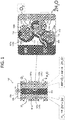
- Fig. 1 is an explanatory view schematically showing the call structure of a conventional general-type solid polymer fuel cell.
- a cell 105 of the solid polymer fuel cell includes a solid polymer film 100 which allows protons (H + ) to permeate therethrough, and a hydrogen-electrode-side electrode 101a and an oxygen-electrode-side electrode 101b arranged on both sides of the solid polymer film 100 respectively.
- a catalyst layer 103 is provided between the solid polymer film 100 and the hydrogen-electrode-side electrode 101a as well as between the solid polymer film 100 and the oxygen-electrode-side electrode 101b.
- a negative electrode active material supply means for supplying a negative electrode active material (hydrogen) to a catalyst layer provided on the hydrogen electrode side (hereinafter referred to as “hydrogen-electrode-side catalyst layer 103a") is provided.
- a positive electrode active material supply means for supplying a positive electrode active material (oxygen) to a catalyst layer provided on the oxygen electrode side (hereinafter referred to as “oxygen-electrode-side catalyst layer 103b") is provided.
- the hydrogen-electrode-side catalyst layer 103a is a part where a reaction that hydrogen supplied as a negative electrode active material is decomposed into protons and electrons is performed. Protons generated in the hydrogen-electrode-side catalyst layer 103a reach an oxygen electrode side through the solid polymer film 100. Electrons reach the oxygen electrode side through a lead line 106 which connects the hydrogen-electrode-side electrode 101a and the oxygen-electrode-side electrode 101b to each other.
- the oxygen-electrode-side catalyst layer 103b is a portion where water is generated by a reaction among oxygen which is supplied as a positive electrode active material, protons which reach the oxygen electrode side from the hydrogen electrode side through the solid polymer film 100, and electrons which reach the oxygen electrode side from the hydrogen electrode side through the lead line 106.
- the cell 105 having such a constitution, by interposing a load 104 in a middle portion of the lead line 106, it is possible to operate the load 104 by electric power generated by the cell 105.
- the oxygen-electrode-side catalyst layer 103b in the conventional cell 105 is, as described in an enlarged view in Fig. 1 , constituted of a catalyst layer constituting body 112, and a proton conduction layer 111 which covers a portion of a surface of the catalyst layer constituting body 112.
- the catalyst layer constituting body 112 is so-called platinum carbon black where catalyst particles 109 which play a main function as a field of reaction are directly carried on a surface of carbon black 110 to which activation treatment is applied.
- the catalyst particles 109 are carried on the surface of the carbon black 110 by way of a carboxylic acid generated on a surface of the carbon black 110 by activation treatment.
- the proton conduction layer 111 is a layer which is formed of a polymer having proton conductivity, and plays a role of supplying protons which reach an oxygen electrode side to the respective catalyst particles 109 through the solid polymer film 100 while connecting a plurality of catalyst layer constituting bodies 112 to each other.
- protons supplied from the solid polymer film 100 through the proton conduction layer 111, electrons supplied from the oxygen-electrode-side electrode 101b through the carbon black 110 which is in contact with the oxygen-electrode-side electrode 101b, and oxygen which permeates a portion of the proton conduction layer 111 formed into a this film shape encounter each other and generate a reaction among them thus forming water.
- the proton conduction layer 111 is merely stuck on the catalyst layer constituting body 112 without generating any outstanding interaction therebetween thus giving rise to a drawback that the proton conduction layer 111 is gradually dissipated due to water generated by a catalytic reaction.
- the catalyst particles 109 which are difficult to supply protons are increased in number and hence, the catalyst particles 109 which contribute to the reaction are decreased in number whereby an electromotive force is lowered. Further, due to the dissipation of the proton conduction layer 111, falling of the catalyst particles from the carbon black 110 occurs thus giving rise to a case where the catalyst particles per se are dissipated.
- the proton conduction polymer which constitutes the proton conduction layer 111 realizes the proton conductivity by an acidic group (acidic side chains)
- the proton conduction layer 111 is liable to be dissolved in water and hence, the proton conduction layer 111 has been a significant factor which causes the deterioration of the catalyst layer.
- catalyst particles are carried on carbon by way of a carrying layer which is constituted of an upper layer and a lower layer.
- the upper layer of the carrying layer is formed by using a polymer having proton conductivity
- the upper layer forming a proton conduction layer which conducts protons generated in the catalyst particles or protons to be supplied to the catalyst particles
- the lower layer of the carrying layer is formed by using a polymer having affinity with both the proton conduction layer and the carbon
- the lower layer forming an adhesive layer which binds the proton conduction layer and carbon to each other.
- the adhesive layer is formed on a surface of the carbon and the proton conduction layer is formed on a surface of the adhesive layer.
- the adhesive layer is formed by using a polymer which contains benzene rings and a structure which exhibits basicity in a molecular structure thereof.
- the proton conduction layer is arranged on carbon by way of the adhesive layer and hence, the dissipation of the proton conduction layer by water can be prevented as much as possible thus suppressing the deterioration of the catalyst layer and the lowering of an electromotive force.
- the polymer which forms the proton conduction layer and the polymer which forms the adhesive layer may be either an organic compound or an inorganic compound or may be a composite of both compounds.
- the catalyst particles used in the catalyst layer constituting body according to this embodiment for example, the catalyst particles used in the catalyst layer constituting body for forming the hydrogen-electrode-side catalyst layer is not particularly limited provided that the catalyst particles function as a catalyst for a reaction which generates at least protons and electrons by decomposing a negative electrode active material.
- the catalyst particles used in the catalyst layer constituting body for forming the oxygen-electrode-side catalyst layer is not particularly limited provided that the catalyst particles function as a catalyst for a reaction among protons, electrons and an anode active material.
- such catalyst particles may be either organic particles or inorganic particles or may be a mixture of both components.
- metal catalyst particles may preferably be used.
- platinum-oriented metal such as platinum, ruthenium, cobalt and the like may be preferably used. It is more preferable to use platinum among these platinum-oriented metals.
- the examples of the catalyst particles described here are only listed for an exemplifying purpose and these examples do not prevent the catalyst layer constituting body of this embodiment from adopting known organic and inorganic catalysts not exemplified in this specification or unknown catalysts which may be found out in future.
- the adhesive layer is formed by using a polymer which contains benzene rings and a structure which exhibits basicity in a molecular structure thereof.
- a polymer for forming the adhesive layer is also simply referred to as an adhesive-layer-forming polymer.
- Benzene rings in the adhesive-layer-forming polymer are stacked on carbon by an interaction with benzene rings on a surface of carbon constituted of carbon and hence, the adhesive layer is firmly fixed to the surface of carbon.
- this interaction is also referred to as "carbon-adhesive layer interaction”.
- the structure of the polymer constituting the adhesive layer which exhibits basicity interacts with an acidic group such as acidic side chains of the polymer constituting the proton conduction layer (hereinafter also simply referred to as "proton conduction layer-forming polymer) and hence, the proton conduction layer is firmly fixed to the adhesive layer.
- this interaction is also referred to as “adhesive layer-proton conduction layer interaction").
- the adhesive layer generates an interaction which becomes an attracting force with respect to both carbon and the proton conduction layer and hence, to consider the catalyst layer constituting body as a whole, the proton conduction layer is fixed more firmly whereby runoff of the proton conduction layer due to moisture or the like can be further prevented.
- the catalyst particles may be carried between the upper layer and the lower layer of the carrying layer, that is, may be carried out in a state where the catalyst particles are arranged between the adhesive layer and the proton conduction layer. Due to such a constitution, it is possible to prevent the catalyst particles from falling from the catalyst layer constituting body.
- the adhesive layer may be formed by using a polymer where atoms having unpaired electrons are contained in a molecular structure thereof.
- a polymer where atoms having unpaired electrons are contained in a molecular structure thereof when the catalyst particles are made of a metal catalyst, the atoms having unpaired electrons generate an interaction with metal atoms in the catalyst particles and hence, it is possible to form the adhesive layer having a bonding function also with respect to the catalyst particles. In the explanation made hereinafter, this interaction is also referred to as "adhesive layer-catalyst particles interaction".
- the proton conduction layer may be formed by using a polymer having acidic side chains.
- a polymer having acidic side chains By forming the proton conduction layer using the polymer having acidic side chains, when the catalyst particles are made of a metal catalyst, it is possible to generate bonding with the proton conduction layer also on the surface of the catalyst and hence, the catalyst layer constituting body can be bonded more firmly.
- the proton conduction layer may be formed by using a polymer having acidic side chains, and the catalyst particles may be carried on a surface of the proton conduction layer. Also with such a constitution, the catalyst particles can be firmly carried on the proton conduction layer.
- carbon is not particularly limited provided that carbon is contained as a main component and carbon has electron conductivity
- the carbon may be one selected from a group consisting of carbon black, graphene and carbon nanotube or a mixture of two or more of these components, for example. Any one of these materials can make benzene rings present on a surface thereof interact with benzene rings of a polymer which constitutes the adhesive layer and hence, it is possible to further prevent the proton conduction layer from running off due to moisture or the like.
- Carbon nanotubes may be multi-layered carbon nanotubes (MWNT) or single-layered carbon nanotubes (SWNT).
- the polymer used to form the adhesive layer may comprise polybenzimidazole as a main component.
- Polybenzimidazole (hereinafter also referred to as "PBI") is a polymer which contains, as a structural formula [Chemical formula 1] expresses, benzene rings which generate a carbon-adhesive layer interaction, portions exhibiting basicity which generate an adhesive layer-proton conduction layer interaction, and atoms ("N" indicated by an arrow) having unpaired electrons which can generate an adhesive layer-catalyst particle interaction in the molecular structure thereof. It is safe to say that polybenzimidazole is one of polymers suitable for forming the adhesive layer.
- X indicates a carbon atom or a nitrogen atom.
- the proton conduction layer may be formed by using a polyvinylphosphonic acid as a main component.
- a polyvinylphosphonic acid (hereinafter also referred to as "PVPA”), as a structural formula [Chemical formula 2] expresses, contains a large number of phosphonic acids as an acidic group in the molecular structure thereof, and exhibits favorable proton conductivity and exhibits bonding property with respect to metal catalyst particles.
- PVPA a phosphonic acid is bonded to each two carbons of a main chain so that PVPA has an extremely large number of acidic groups. Accordingly, even when moisture is not supplied to PVPA, PVPA can realize proton conductivity by hopping. Accordingly, it is unnecessary to provide water in a liquid form which has been necessary for proton conduction in conventional fuel cells, it is unnecessary to provide a device for cooling a fuel cell, and it is possible to provide a cell or a fuel cell which has an extremely wide use temperature range.
- the electrode provided with a catalyst By stacking the above-mentioned catalyst layer constituting body on an electrode sheet having conductivity such as carbon paper, it is possible to form the electrode provided with a catalyst where the electrode and the catalyst layer are integrally bonded to each other. According to the electrode provided with such a catalyst, it is possible to provide the electrode provided with a catalyst which can prevent the runoff of the proton conduction polymer from the catalyst layer even when moisture is generated.
- the above-mentioned electrode provided with a catalyst may be used as any one of an oxygen electrode, a hydrogen electrode or both electrodes, for example, by using the electrode provided with a catalyst at least as the electrode on an oxygen electrode side, it is possible to prevent a runoff of the proton conduction polymer which may be caused by moisture generated by a reaction.
- a cell can be formed by using such an electrode provided with a catalyst or a fuel cell can be formed by making use of such a cell.
- a solid polymer film provided with a catalyst may be formed such that the above-mentioned catalyst layer constituting body is stacked at least on a surface of the solid polymer film on an oxygen electrode side thus forming a catalyst layer.
- Such a solid polymer film provided with a catalyst can, even when moisture is generated, prevent a runoff of the proton conduction polymer from the catalyst layer.
- the catalyst layer formed on the above-mentioned solid polymer film may be formed on any one of an oxygen-electrode-side surface, a hydrogen-electrode-side surface or both surfaces, by forming the catalyst layer at least on the oxygen-electrode-side surface, for example, it is possible to prevent a runoff of the proton conduction polymer which may be caused by moisture generated by a reaction.
- a cell can be formed by using such a solid polymer film provided with a catalyst or a fuel cell can be formed by making use of such a cell.
- the catalyst layer constituting body according to this embodiment can be prepared by a method of preparing a catalyst layer constituting body of a fuel cell where catalyst particles are carried on carbon, wherein the method includes the steps of: obtaining adhesive-layer-forming polymer deposited carbon where a adhesive-layer-forming polymer is deposited on a surface of the carbon with a large film thickness by preparing a first dispersion medium by dissolving the adhesive-layer-forming polymer which includes a benzene ring and atoms having unpaired electrons in a molecular structure in a first solvent which exhibits solubility to the adhesive-layer-forming polymer, by dispersing the carbon into the first dispersion medium and, thereafter, by collecting a filtered residue after filtering the first dispersion medium; forming adhesive layer formed carbon where a thin-film-like adhesive layer is formed on a surface of the carbon by removing an extra adhesive-layer-forming polymer deposited on the surface of the carbon due to cleaning of the adhesive-layer-forming polymer deposited carbon with the first
- the adhesive layer is formed on the surface of carbon
- the proton conduction layer is formed on the surface of the adhesive layer
- the catalyst particles are arranged between the adhesive layer and the proton conduction layer.
- the method of preparing a catalyst layer constituting body is also referred to as a method of carrying and preparing a catalyst between two layers.
- the method of carrying and preparing a catalyst between two layers includes: the step of obtaining adhesive-layer-forming polymer deposited carbon; the step of forming adhesive layer formed carbon; the step of forming catalyst-deposited carbon; the step of obtaining proton conduction layer-forming polymer deposited carbon; and the step of obtaining a catalyst layer constituting body.
- the first solvent used in the step of obtaining adhesive-layer-forming polymer deposited carbon in the method of carrying and preparing a catalyst between two layers is not particularly limited provided that the first solvent is a solvent which exhibits solubility to the adhesive-layer-forming polymer.
- the adhesive-layer-forming polymer is PBI,dimethylacetamide (DMAc) can be preferably used as the first solvent.
- a first dispersion medium used in the step of obtaining adhesive-layer-forming polymer deposited carbon is a dispersion medium for dispersing carbon, and adhesive-layer-forming polymer deposited carbon can be prepared by dissolving a predetermined amount of adhesive-layer-forming polymer in the first solvent.
- a known method can be used provided that the known method is a filtering method by which carbon to which adhesive-layer-forming polymer is deposited is filtered and collected from the first dispersion medium.
- suction filtering is named where carbon to which the adhesive-layer-forming polymer is bonded can be trapped using a filter paper or a membrane (hereinafter, these parts being collectively referred to as a filter medium).
- Adhesive-layer-forming polymer deposited carbon can be obtained by collecting a filtered residue (filtered material) which is filtered on a filter medium by filtering. Adhesive-layer-forming polymer deposited carbon obtained in this manner exhibits a state where adhesive-layer-forming polymer is deposited on a surface of carbon with a large film thickness thus having a adhesive-layer-forming polymer of an amount exceeding an amount necessary for functioning as an adhesive layer (extra amount).
- the adhesive-layer-forming polymer having a large film thickness deposited on a surface of carbon contains the adhesive-layer-forming polymer in the vicinity of the surface of carbon which constitutes the adhesive layer and the extra adhesive-layer-forming polymer deposited on an upper layer of the adhesive-layer-forming polymer in the vicinity of the surface of carbon. Accordingly, as the next step, the step of forming adhesive layer formed carbon by removing the extra adhesive-layer-forming polymer is performed.
- the extra adhesive-layer-forming polymer is removed by cleaning the filtered residue obtained in the step of obtaining the adhesive-layer-forming polymer deposited carbon with the first solvent.
- An amount of extra adhesive-layer-forming polymer is determined based on a thickness of the adhesive layer formed on the surface of carbon.
- the thickness of the adhesive layer may be a thickness of a level at which a carbon-adhesive layer interaction, an adhesive layer-proton conduction layer interaction and an adhesive layer-catalyst particles interaction can be generated, and electrons are movable between carbon and catalyst particles. Accordingly, it is safe to say that the adhesive-layer-forming polymer which is bonded with a thickness exceeding such a thickness constitutes the extra adhesive-layer-forming polymer.
- the adhesive-layer-forming polymer is PBI
- the thickness of the adhesive layer is set to 1 to 5 nm, and is more preferably set to 2 to 3 nm.
- the cleaning performed in the step of forming the adhesive layer formed carbon is performed by filtering which is performed by adding a first solvent to the adhesive-layer-forming polymer deposited carbon which is obtained by filtering in the step of obtaining adhesive-layer-forming polymer deposited carbon.
- the cleaning can be realized such that the adhesive-layer-forming polymer deposited carbon is obtained on the filter medium by suction filtering and, subsequently, the adhesive-layer-forming polymer deposited carbon is filtered while being rinsed with the first solvent while adding the first solvent on the filter medium. Due to such an operation, adhesive layer formed carbon can be formed on the filter medium.
- a method can remove an extra adhesive-layer-forming polymer, cleaning performed in this step is not limited to the above-mentioned method. For example, it is needless to say that adhesive-layer-forming polymer deposited carbon is dispersed in the first solvent once and, thereafter, the adhesive-layer-forming polymer deposited carbon is filtered.
- the step is performed where catalyst particles are deposited on the obtained adhesive layer formed carbon thus generating catalyst-deposited carbon.
- the second dispersion medium used in the step of generating the catalyst-deposited carbon is not particularly limited provided that the adhesive layer formed carbon can be dispersed in the dispersion medium, and a state where the catalyst particles are bonded to the surface of the adhesive layer can be brought about.
- a second dispersion medium for example, an ethylene glycol aqueous solution of 10 to 100 % can be used. It is more preferable to use an ethylene glycol aqueous solution of 55 to 65 %.
- deposited means a state where adhesive layer formed carbon and catalyst particles are present in mixture in the second dispersion medium and the catalyst particles are bonded to a surface of the adhesive layer.
- bonding is a concept which also includes a state where catalyst particles bonded to a surface of the adhesive layer by growing the catalyst raw-material component on the surface of the adhesive layer and hence, “bonded” is a state also includes a state where catalyst particles bonded of the surface of the adhesive layer are brought into a state where catalyst particles deposited on a surface of the adhesive layer.
- a method where catalyst particles are grown while reducing metal salt of the metal in a second dispersion medium there can be named a method where catalyst particles are grown while reducing metal salt of the metal in a second dispersion medium.
- metal salt for example, a chloroplatinic acid (H 2 PtCl 6 -6H 2 O) can be preferably used when the catalyst particles are formed by using platinum.
- a second solvent used in the step of obtaining proton conduction layer-forming polymer deposited carbon is not particularly limited provided that the second solvent is a solvent which can resolve a proton conduction layer-forming polymer.
- the second solvent is a solvent which can resolve a proton conduction layer-forming polymer.
- water can be used as the second solvent.
- a third dispersion medium used in the step of obtaining proton conduction layer-forming polymer deposited carbon is used for depositing the proton conduction layer-forming polymer on a surface of catalyst-deposited carbon by dispersing the catalyst-deposited carbon in the dispersion medium.
- the third dispersion medium can be prepared by dissolving the proton conduction layer-forming polymer in the second solvent.
- the filtering which is performed in the step of obtaining the proton conduction layer-forming polymer deposited carbon
- a known method can be used provided that the method is a filtering method which can filter and collect carbon on which the proton conduction layer-forming polymer is deposited from the third dispersion medium.
- suction filtering or the like it is possible to adopt suction filtering or the like in the same manner as the previously-mentioned step of obtaining the adhesive-layer-forming polymer deposited carbon.
- Proton conduction layer-forming polymer deposited carbon can be obtained by collecting a filtered residue (filtered material) which is filtered on a filter medium by filtering.
- Proton conduction layer-forming polymer deposited carbon obtained in this manner exhibits a state where proton conduction layer-forming polymer is deposited on a surface of an adhesive layer and catalyst particles with a large film thickness thus having a proton conduction layer-forming polymer of an amount exceeding an amount necessary for functioning as a proton conduction layer (extra amount).
- the proton conduction layer-forming polymer having a large thickness deposited on the surface of the adhesive layer and the catalyst particles contains the proton conduction layer-forming polymer in the vicinity of the adhesive layer and catalyst particles which is necessary for constituting the proton conduction layer and the extra proton conduction layer-forming polymer. Accordingly, as the next step, the step of generating the proton conduction layer formed carbon, that is, the catalyst layer constituting body according to this embodiment is performed by removing the extra proton conduction layer-forming polymer.
- the extra proton conduction layer-forming polymer is removed by cleaning the filtered residue obtained in the step of obtaining the proton conduction layer-forming polymer deposited carbon by the second solvent.
- An amount of extra proton conduction layer-forming polymer is determined based on a thickness of the proton conduction layer formed on the surface of the adhesive layer and the catalyst particles.
- the thickness of the proton conduction layer may be a thickness of a level at which an adhesive layer-proton conduction layer interaction and a proton conduction layer- catalyst particles interaction can be generated, and a positive electrode active material (for example, molecular oxygen) or a negative electrode active material (for example, molecular hydrogen) are permeable between the surface of proton conduction layer and catalyst particles. Accordingly, it is safe to say that the proton conduction layer-forming polymer which is deposited exceeding such a thickness constitutes the extra proton conduction layer-forming polymer.
- the thickness of the proton conduction layer is set to 1 to 5 nm, and is more preferably set to 2 to 3 nm.
- the cleaning in the step of forming the catalyst layer constituting body can be performed by filtering which is performed by adding a second solvent to the proton conduction layer-forming polymer deposited carbon which is obtained by filtering in the step of obtaining proton conduction layer-forming polymer deposited carbon.
- the cleaning can be realized such that the proton conduction layer-forming polymer deposited carbon is obtained on the filter medium by suction filtering and, subsequently, the proton conduction layer-forming polymer deposited carbon is filtered while adding the second solvent on the filter medium. Due to such an operation, catalyst layer constituting body can be formed on the filter medium.
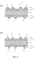
- the catalyst layer constituting body A prepared by the above-mentioned method of carrying and preparing a catalyst between two layers is configured such that, as shown in Fig. 2 (a) , an adhesive layer 12 is formed on a surface (upper layer) of carbon 10, and a proton conduction layer 14 is formed on a surface (upper layer) of the adhesive layer 12, and catalyst particles 16 are carried between the adhesive layer 12 and the proton conduction layer 14.
- the adhesive layer 12 and the proton conduction layer 14 function also as a carrying layer 18 which carries the catalyst particles 16.
- the carbon 10 is expressed as carbon nanotube as an example of the catalyst layer constituting body A in Fig. 2 (a) , as described previously, the carbon 10 is not limited to the carbon nanotube.
- a cleaning operation is performed in the step of generating adhesive layer formed carbon and the step of forming the catalyst layer constituting body respectively so as to remove the extra adhesive-layer-forming polymer and the proton conduction layer-forming polymer.
- a thickness of the carrying layer 18 can be set to an appropriate value and hence, it is possible to perform the transaction of electrons between an electrode and a catalyst layer constituting body which is in contact with the electrode. To be more specific, it is possible to perform the transmission and the reception of electrons between the electrode and carbon of the catalyst layer constituting body thorough the carrying layer 18.
- a method of preparing a catalyst layer constituting body of a fuel cell where catalyst particles are carried on carbon including the steps of: obtaining adhesive-layer-forming polymer deposited carbon where a adhesive-layer-forming polymer is deposited on a surface of the carbon with a large film thickness by preparing a first dispersion medium by dissolving the adhesive-layer-forming polymer which includes benzene rings and a structure which exhibits basicity in a molecular structure in a first solvent which exhibits solubility to the adhesive-layer-forming polymer, by dispersing the carbon into the first dispersion medium and, thereafter, by collecting a filtered residue after filtering the first dispersion medium; generating adhesive layer formed carbon where a thin-film-like adhesive layer is formed on a surface of the carbon by removing an extra adhesive-layer-forming polymer deposited on the surface of the carbon by cleaning the adhesive-layer-forming polymer deposited carbon using the
- the adhesive layer is formed on the surface of carbon
- the proton conduction layer is formed on the surface of the adhesive layer
- the catalyst particles are arranged on the surface of the proton conduction layer.
- the method of preparing a catalyst layer constituting body is also referred to as a proton conduction layer catalyst carrying and preparing method. Further, with respect to the steps substantially equal to the steps of the above-mentioned method of carrying and preparing a catalyst between two layers, the explanation of the steps may be omitted partially.
- the proton conduction layer catalyst carrying and preparing method includes: the step of obtaining adhesive-layer-forming polymer deposited carbon; the step of generating adhesive layer formed carbon; the step of obtaining proton conduction layer-forming polymer deposited carbon; the step of generating proton conduction layer formed carbon; and the step of obtaining a catalyst layer constituting body.
- the first solvent and the first dispersion medium used in the step of obtaining adhesive-layer-forming polymer deposited carbon in the proton conduction layer catalyst carrying and preparing method are substantially equal to the first solvent and the first dispersion medium used in the above-mentioned method of carrying and preparing a catalyst between two layers.
- the adhesive-layer-forming polymer is PBI
- DMAc can be preferably used as the first solvent.
- the first dispersion medium can be prepared by dissolving a predetermined amount of adhesive layer formed-polymer in the first solvent.
- the filtering is also performed in the same manner as the above-mentioned method of carrying and preparing a catalyst between two layers used in the first embodiment, and steps of generating adhesive layer formed carbon are substantially equal to the steps of the method of carrying and preparing a catalyst between two layers used in the first embodiment.
- a step of obtaining a proton conduction layer-forming polymer deposited carbon by depositing a proton conduction layer-forming polymer on a surface of the adhesive layer is performed.
- a second solvent used in the step of obtaining proton conduction layer-forming polymer deposited carbon is not particularly limited provided that the second solvent is a solvent which can resolve a proton conduction layer-forming polymer.
- the second solvent is a solvent which can resolve a proton conduction layer-forming polymer.
- water can be used as the second solvent.
- a second dispersion medium used in the step of obtaining proton conduction layer-forming polymer deposited carbon is used for depositing the proton conduction layer-forming polymer on a surface of adhesive layer formed carbon by dispersing the adhesive layer formed carbon in the dispersion medium.
- the second dispersion medium can be prepared by dissolving the proton conduction layer-forming polymer in the second solvent.
- the filtering which is performed in the step of obtaining the proton conduction layer-forming polymer deposited carbon
- a known method can be used provided that the method is a filtering method which can filter and collect carbon on which the proton conduction layer-forming polymer is deposited from the second dispersion medium.
- suction filtering or the like it is possible to adopt suction filtering or the like in the same manner as the previously-mentioned method of carrying and preparing a catalyst between two layers.
- Proton conduction layer-forming polymer deposited carbon can be obtained by collecting a filtered residue (filtered material) which is filtered by filtering.
- Proton conduction layer-forming polymer deposited carbon obtained in this manner exhibits a state where proton conduction layer-forming polymer is deposited on a surface of an adhesive layer with a large film thickness thus having a proton conduction layer-forming polymer of an amount exceeding an amount necessary for functioning as a proton conduction layer (extra amount).
- the step of generating the proton conduction layer formed carbon by removing the extra proton conduction layer-forming polymer is performed.
- the extra proton conduction layer-forming polymer is removed by cleaning the filtered residue obtained in the step of obtaining the proton conduction layer-forming polymer deposited carbon by the second solvent.
- An amount of extra proton conduction layer-forming polymer is determined based on a thickness of the proton conduction layer formed on the surface of the adhesive layer.
- the thickness of the proton conduction layer may be a thickness of a level at which an adhesive layer-proton conduction layer interaction and a proton conduction layer-catalyst particles interaction which is expected between the proton conduction layer and catalyst particles deposited on a surface (upper surface) of the proton conduction layer in a later step can be generated, and electrons are permeable between carbon and catalyst particles, that is, by way of the adhesive layer and the proton conduction layer (by way of the carrying layer.
- the proton conduction layer-forming polymer which is deposited exceeding such a thickness constitutes the extra proton conduction layer-forming polymer.
- the thickness of the proton conduction layer is set to 1 to 5nm, and is more preferably set to 2 to 3nm.
- the cleaning performed in the step of generating the proton conduction layer formed carbon is performed by filtering which is performed by adding a second solvent to the proton conduction layer-forming polymer deposited carbon which is obtained by filtering in the step of obtaining proton conduction layer-forming polymer deposited carbon.
- the cleaning can be realized such that the proton conduction layer-forming polymer deposited carbon is obtained on the filter medium by suction filtering and, subsequently, the proton conduction layer-forming polymer deposited carbon is filtered while adding the second solvent to the filter medium. Due to such an operation, the proton conduction layer formed carbon can be generated on the filter medium.
- a step of generating catalyst-deposited carbon by depositing catalyst particles on the proton conduction layer formed carbon that is, a step of forming a catalyst layer constituting body is performed.
- the third dispersion medium used in the step of forming the catalyst layer constituting body is not particularly limited provided that the proton conduction layer formed carbon can be dispersed in the third dispersion medium, and a state where the catalyst particles are deposited on the surface of the proton conduction layer can be brought about.
- a third dispersion medium for example, an ethylene glycol aqueous solution of 10 to 100 % can be used. It is more preferable to use an ethylene glycol aqueous solution of 55 to 65 %.
- deposited means a state where proton conduction layer formed carbon and catalyst particles are present in mixture in the third dispersion medium so that the catalyst particles are bonded to a surface of the proton conduction layer.
- deposited is a concept which also includes a state where catalyst particles bonded to a surface of the proton conduction layer are formed by growing a catalyst raw-material component on the surface of the proton conduction layer by adding the catalyst raw-material component together with the proton conduction layer formed carbon.
- a method where catalyst particles are grown while reducing metal salt of the metal in a third dispersion medium there can be named a method where catalyst particles are grown while reducing metal salt of the metal in a third dispersion medium.
- metal salt for example, a chloroplatinic acid (H 2 PtCl 6 -6H 2 O) can be preferably used.
- the catalyst layer constituting body B prepared by the above-mentioned proton conduction layer catalyst carrying and preparing method is configured such that, as shown in Fig. 2 (b) , an adhesive layer 12 is formed on a surface (upper layer) of carbon 10, and a proton conduction layer 14 is formed on a surface (upper layer) of the adhesive layer, and catalyst particles 16 are carried on a surface of the proton conduction layer 14.
- the adhesive layer 12 and the proton conduction layer 14 function also as a carrying layer 18 which carries the catalyst particles 16.
- the carbon 10 is expressed as carbon nanotube as an example of the catalyst layer constituting body B in Fig. 2 (b) , as described previously, the carbon 10 is not limited to the carbon nanotube.
- a cleaning operation is performed in the step of generating adhesive layer formed carbon and the step of generating the proton conduction layer formed carbon respectively so as to remove the extra adhesive-layer-forming polymer and the proton conduction layer-forming polymer. Accordingly, a thickness of the carrying layer 18 can be set to an appropriate value and hence, it is possible to perform the transaction of electrons between an electrode and a catalyst layer constituting body which is in contact with the electrode. To be more specific, it is possible to perform the transmission and the reception of electrons between the electrode and carbon of the catalyst layer constituting body through the carrying layer 18.
- the preparation of a catalyst layer constituting body in this example is performed by a method of carrying and preparing a catalyst between two layers in accordance with steps shown in Fig. 3 .
- Multi-layered carbon nanotubes are used as carbon
- PBI is used as a adhesive-layer-forming polymer
- PVPA is used as a proton conduction layer-forming polymer.
- Catalyst particles are made of platinum. Catalyst particles are formed such that catalyst particles are made to grow on a surface of an adhesive layer using chloroplatinic acid (H 2 PtCl 6 ⁇ 6H 2 O) as a catalyst raw-material component.
- MWNT covered with PBI that is, adhesive layer formed carbon
- MWNT/PBI MWNT covered with PBI
- An intermediate product such as proton conduction layer formed carbon and a catalyst layer constituting body may also be expressed using the substantially same format.
- a first dispersion medium is prepared by sufficiently dissolving polybenzimidazole (PBI: 4mg) which constitutes a adhesive-layer-forming polymer into dimethyl acetamide (DMAc: 20ml, KISHIDA CHEMICAL Co.,Ltd.) which constitutes a first solvent.
- PBI polybenzimidazole
- DMAc dimethyl acetamide
- multi-layered carbon nanotubes (MWNT: 20mg, made by NIKKISO CO., LTD.) which constitutes carbon is added to the first dispersion medium, and sonication is applied to the first dispersion medium using a bath-type sonicator (5510, made by BRANSON) for 2 hours.
- Such a solution is preliminarily filtered using a gauze, and the filtered solution is subjected to the suction filtration (membrane filter 0.2 ⁇ m PTFE) .
- Adhesive-layer-forming polymer deposited carbon is obtained on a membrane filter which constitutes a filter medium (step of obtaining adhesive-layer-forming polymer deposited carbon).
- the adhesive-layer-forming polymer deposited carbon on the membrane filter is sufficiently cleaned using DMAc (first solvent) which is a solvent having a favorable affinity with PBI.
- DMAc first solvent
- Black powder remaining after cleaning is collected on a filter paper, and is dried at 60°C under a reduced pressure for 4 to 6 hours.
- 13mg of MWNT/PBI which constitutes adhesive layer formed carbon is obtained (step of generating adhesive layer formed carbon).
- MWNT/PBI/Pt that is, catalyst-deposited carbon is generated.
- 60% ethylene glycol solution (30ml) and MWNT/PBI (15mg) which constitute a second dispersion medium are charged in a sample bottle, and the second dispersion medium is subjected to a sonication.
- a catalyst raw-material solution which is obtained by dissolving chloroplatinic acid (H 2 PtCl 6 ⁇ 6H 2 O, 36mg) which constitutes a catalyst raw-material component into 60% ethylene glycol solution (45ml) is added in the sample bottle, and MWNT/PBI and the catalyst raw-material solution are sufficiently mixed.
- MWNT/PBI/Pt has the constitution of catalyst-deposited carbon which obtained MWNT/PBI/Pt is expected to have.
- the observation is made using an electron microscope with respect to whether or not an adhesive layer made of PBI is formed on the MWNT and catalyst particles are deposited on the adhesive layer.
- FIG. 4 A microscopic examination image of the MWNT/PBI/Pt is shown in Fig. 4 , Fig. 5 and in a photograph on a left side in Fig. 6 .
- the catalyst-deposited carbon is observed in a state where a large number of fibers are gathered in an overlapping manner or in a folded manner.
- an STEM image shown in Fig. 4(b) it is observed that a countless black spots are deposited along the MWNT.
- Fig. 5 shows a further enlarged microscopic examination image.
- STEM image shown in Fig. 5 (a) it is observed that countless catalyst particles made of platinum are deposited on a periphery of MWNT.
- a state shown in the schematic view where catalyst particles are deposited on the periphery of MWNT by way of an adhesive layer is observed from an STEM image shown in Fig. 5(b) .
- MWNT/PBI/Pt has the constitution which catalyst-deposited carbon is required to have, that is, the structure where an adhesive layer made of PBI is formed on MWNT, and catalyst particles are deposited on the adhesive layer.
- Fig. 7 shows a microscopic examination image showing a boundary on MWNT between a portion where the adhesive layer made of PBI is formed and a portion where the adhesive layer made of PBI is not formed.
- MWNT/PBI/Pt/PVPA that is, a catalyst layer constituting body is formed.
- Water (30ml) which constitutes a second solvent and PVPA 30% aqueous solution (2mL: made by Polysciences) which constitutes a proton conduction layer-forming polymer are charged in a 50ml sample bottle, and water and the aqueous solution are stirred thus preparing a third dispersion medium.
- MWNT/PBI/Pt (10mg) is added to the third dispersion medium, and MWNT/PBI/Pt is sufficiently dispersed into the third dispersion medium by applying sonication to the mixture for 5 minutes.
- This dispersing liquid is stirred at a room temperature for 6 hours and, thereafter, is filtered using a membrane filter (1.0 ⁇ m:PTFE).
- Proton conduction layer-forming polymer deposited carbon is obtained on the membrane filter which constitutes a filter medium (step of obtaining proton conduction layer-forming polymer deposited carbon).
- the proton conduction layer-forming polymer deposited carbon on the membrane filter is sufficiently cleaned using water (second solvent), and is dried at 60°C under a reduced pressure for 4 to 6 hours (together with phosphorus pentaoxide which constitutes a desiccant). Due to such steps, 11.04mg of MWNT/PBI/Pt/PVPA which constitutes a catalyst layer constituting body is obtained (step of forming catalyst layer constituting body).
- MWNT/PBI/Pt/PVPA has the constitution of a catalyst layer constituting body which obtained MWNT/PBI/Pt/PVPA is expected to have.
- MWNT/PBI/Pt/PVPA has the constitution where an adhesive layer is formed on a surface (upper layer) of MWNT, a proton conduction layer made of PVPA is formed on a surface (upper layer) of the adhesive layer, and catalyst particles are carried between the adhesive layer and the proton conduction layer.
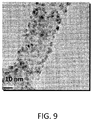
- a photograph on a right upper side in Fig. 6 shows an SEM image of MWNT/PBI/Pt/PVPA
- a photograph on a right lower side in Fig. 6 and Fig. 9 show an STEM image of MWNT/PBI/Pt/PVPA. From the STEM image shown on the right side in Fig. 6 and the STEM image shown in Fig. 9 , it is observed that catalyst particles are held on a periphery of MWNT in a state where the catalyst particles are covered with PVPA.
- a dark solid line indicates spectrum of MWNT/PBI/Pt/PVPA
- a light solid line indicates spectrum of MWNT/PBI/Pt.
- both MWNT/PBI/Pt and MWNT/PBI/Pt/PVPA which are obtained by preparation include an adhesive layer made of PBI.
- both MWNT/PBI/Pt and MWNT/PBI/Pt/PVPA which are obtained by preparation include catalyst particles made of platinum.
- MWNT/PBI/Pt/PVPA obtained by the method of carrying and preparing a catalyst between two layers has the constitution of the catalyst layer constituting body. That is, MWNT/PBI/Pt/PVPA has the constitution where an adhesive layer is formed on a surface (upper layer) of MWNT, a proton conduction layer made of PVPA is formed on a surface (upper layer) of the adhesive layer, and catalyst particles are carried between the adhesive layer and the proton conduction layer.
- MWNT/PBI/Pt where catalyst particles are exposed to an outer surface of MWNT/PBI/Pt and MWNT/PBI/Pt/PVPA where surfaces of catalyst particles are covered with a proton conduction layer are used as objects to be compared to each other.
- the evaluation is made based on electrochemical catalytic activity (ECSA) of MWNT/PBI/Pt and electrochemical catalytic activity (ECSA) of MWNT/PBI/Pt/PVPA measured by an electrochemical measurement.
- a catalyst layer constituting body is prepared by a proton conduction layer catalyst carrying and preparing method.
- the preparation of the catalyst layer constituting body by the proton conduction layer catalyst carrying and preparing method differs from the preparation of the catalyst layer constituting body by the above-mentioned method of carrying and preparing a catalyst between two layers mainly with respect to timing at which catalyst-deposited carbon is formed. Accordingly, the explanation is omitted with respect to the details of the operations of the respective methods.
- multi-layered carbon nanotubes are used as carbon
- PBI is used as a adhesive-layer-forming polymer
- PVPA is used as a proton conduction layer-forming polymer.
- Catalyst particles are made of platinum. Catalyst particles are formed such that catalyst particles are made to grow on a surface of an adhesive layer using a chloroplatinic acid (H 2 PtCl 6 ⁇ 6H 2 O) as a catalyst raw-material component.
- MWNT covered with PBI that is, adhesive layer formed carbon is formed. That is, MWNT/PBI which constitutes adhesive layer formed carbon is obtained by performing steps substantially equal to the steps of obtaining adhesive-layer-forming polymer deposited carbon and the steps of generating adhesive layer formed carbon.
- MWNT/PBI/PVPA/Pt that is, the catalyst layer constituting body is formed.
- MWNT/PBI/PVPA/Pt has the constitution of a catalyst layer constituting body which obtained MWNT/PBI/PVPA/Pt is expected to have.
- MWNT/PBI/PVPA/Pt has the constitution where an adhesive layer is formed on a surface (upper layer) of MWNT, a proton conduction layer made of PVPA is formed on a surface (upper layer) of the adhesive layer, and catalyst particles are carried on a surface of the adhesive layer.
- catalyst particles are brought into a state where the catalyst particles are exposed on a surface of the catalyst layer constituting body and hence, the evaluation of a surface area of electrochemical catalytic activity (ECSA) is omitted.
- ECSA electrochemical catalytic activity
- inventors have studied runoff of a proton conduction layer caused by moisture using two kinds of prepared catalyst layer constituting bodies (MWNT/PBI/Pt/PVPA and MWNT/PBI/PVPA/Pt) according to this embodiment and one catalyst layer constituting body provided with no adhesive layer (MWNT/Nafion/Pt) .
- the respective catalyst layer constituting bodies are added in a flask which is filled with a predetermined amount of water, and the catalyst layer constituting bodies and water are sufficiently stirred and, thereafter, are filtered. An obtained filtered material is observed using an electron microscope.
- both of two kinds of catalyst layer constituting bodies according to this embodiment maintain the constitutions substantially equal to the constitutions of the catalyst layer constituting bodies before the examination is performed.
- the catalyst layer constituting body provided with no adhesive layer as can be understood from a microscopic examination image shown in Fig. 12 , it is observed that a proton conduction layer (Nafion) runs off and platinum which constitutes catalyst particles is separated in a coagulated manner.
- the catalyst layer constituting body according to this embodiment can prevent runoff of a proton conduction layer (PVPA) . That is, it is proved that the catalyst layer constituting body can prevent runoff of the proton conductive polymer from the catalyst layer even when moisture is generated during an operation of a fuel cell.
- PVPA proton conduction layer
- catalyst particles are not removed even under such strict conditions and hence, it is suggested that lowering of an electromotive force or the like attributed to the removal catalyst particles can be also suppressed.
- an electrode provided with a catalyst is formed by using the obtained catalyst layer constituting body (MWNT/PBI/Pt/PVPA), and an electrode provided with a catalyst is formed by using the obtained catalyst layer constituting body (MWNT/PBI/PVPA/Pt).
- a catalyst layer constituting body dispersing liquid is prepared by dispersing 12mg of a catalyst layer constituting body into a 2-propanol 80% aqueous solution which constitutes a dispersion medium.
- the catalyst layer constituting body dispersing liquid is supplied to a suction filtration device where a filter medium is formed of a carbon paper (made by SGL Carbon, thickness: 246 ⁇ m), and a catalyst layer constituting body is deposited on the carbon paper thus forming a catalyst layer.
- the carbon paper has conductivity, and plays a role of an electrode sheet which constitutes a portion of the cell.
- a state where the catalyst layer constituting body (MWNT/PBI/Pt/PVPA) is deposited on a surface of the carbon paper is shown in a lower portion of Fig. 13 .
- the carbon paper on which the catalyst layer constituting body is deposited is cut into a predetermined size (1cm square, for example), and the cut material is used as an electrode provided with a catalyst.
- the catalyst layer formed into the electrode provided with a catalyst is configured such that catalyst layer constituting bodies observed as long fibers are deposited in a non-woven fabric state. The substantially same constitution is observed in the result of a microscope examination of an electrode provided with a catalyst formed by using MWNT/PBI/PVPA/Pt.
- a cell is formed by using an electrode provided with a catalyst obtained in the above-mentioned [4. Manufacture of electrode provided with a catalyst].
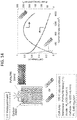
- a mixed film of PVPA and PBI is used as a solid polymer film and, as shown in Fig. 13 , the solid polymer film is sandwiched by electrodes provided with a catalyst from both surfaces of the solid polymer film thus forming a cell shown in a schematic view on a left side in Fig. 14 .
- a negative electrode active material supply means for supplying a negative electrode active material to a catalyst layer and a positive electrode active material supply means for supplying a positive electrode active material to a catalyst layer are omitted for the convenience of the explanation.
- an actually formed cell includes these active material supply means and other members necessary for the constitution of the cell.
- the mixed film of PVPA and PBI is formed such that PBI and PVPA are dissolved in a DMAc (dimethyl acetamide) solution, and the solution is casted on a glass plate and is dried. Further, the solid polymer film is sandwiched by the electrodes provided with a catalyst in a state where a catalyst layer side of the electrode provided with a catalyst faces a solid polymer film in an opposed manner.
- DMAc dimethyl acetamide
- a temperature of the cell is set to 120°C, hydrogen is supplied as a negative electrode active material, and air is supplied as a positive electrode active material.
- An amount of platinum applied to the electrode provided with a catalyst for the examination is 0.45mg per 1cm 2 .
- a cell which includes a catalyst layer formed by using MWNT/PBI/Pt is used as a comparison object.
- a result of the comparison is shown on a right side of Fig. 14 .
- the cell according to this embodiment has a high power density compared to the cell which constitutes the comparison object.
- the cell or the fuel cell according to this embodiment can exhibit an extremely excellent performance.
- the illustration of specific data is omitted, it is understood that the cell which uses the electrode provided with a catalyst formed by using MWNT/PBI/PVPA/Pt can also acquire the performance substantially equal to the performance of the cell which uses the electrode provided with a catalyst formed by using MWNT/PBI/Pt/PVPA.
- inventors have studied a change in an electromotive force characteristic attributed to runoff of a proton conduction layer caused by water with respect to a catalyst layer constituting body provided with an adhesive layer according to this embodiment and a conventional catalyst layer constituting body.
- the inventors have studied a change in an electromotive force characteristic of a cell formed by using a catalyst layer constituting body which is already cleaned with water compared to a cell formed by using a catalyst layer constituting body which is not yet cleaned with water.
- an electromotive force characteristic of the cell formed by using the conventional catalyst layer constituting body (already cleaned with water) is largely deteriorated due to runoff of a proton conduction layer-forming polymer compared to the cell formed by using the conventional catalyst layer constituting body (not yet cleaned with water) .
- an electromotive force characteristic of the cell (MWNT/PBI/Pt/PVPA and MWNT/PBI/PVPA/Pt) formed by using the catalyst layer constituting body (already cleaned with water) according to this embodiment is not deteriorated due to runoff of a proton conduction layer-forming polymer even compared to the cell formed by using a catalyst layer constituting body (not yet cleaned with water) according to the present invention.
- the catalyst layer constituting body according to this embodiment can prevent runoff of the proton conduction layer (PVPA) . That is, it is proved that the catalyst layer constituting body can prevent runoff of the proton conductive polymer from the catalyst layer even when moisture is generated by an operation of a fuel cell.
- PVPA proton conduction layer
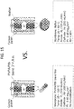
- a comparison test is carried out between a cell (MWNT/PBI/Pt/PVPA) according to this embodiment and a conventional-type cell ( Fig. 15 ).
- a cell shown in Fig. 1 where Nafion (registered trademark) is used as a solid polymer film is used as a conventional-type cell which constitutes a comparison object.
- Humidification is required in generating electric power in this comparison object cell and hence, hydrogen which constitutes a negative electrode active material is supplied to the cell in a state where the cell is humidified to 90% or more.
- humidification is unnecessary in the cell according to this embodiment and hence, the cell is not humidified.
- Fig. 16 The result of the comparison test is shown in Fig. 16 .
- the graphs on an upper side of Fig. 16 show a temperature characteristic of the cell according to this embodiment, and a Table on a lower side of Fig. 16 shows a comparison between the cell according to this embodiment and the conventional-type cell.
- the cell according to this embodiment can obtain electric power substantially equal to that of the conventional-type cell.
- the substantially same result is also obtained with respect to the cell (MWNT/PBI/PVPA/Pt) according to this embodiment from the test carried out by the inventors of the present invention.
- the conventional-type cell requires water in a liquid form in generating electric power and hence, it is necessary to operate the conventional-type cell in a temperature range below 100°C at most.
- the cell according to this embodiment when a proton conduction layer is formed by using PVPA, the conduction of protons can be realized without requiring water in a liquid form so that the cell can be operated in a wide temperature range beyond 100°C.
- the cooling mechanism for cooling the cell at a temperature where water can be maintained in a liquid state is unnecessary in operating a fuel cell which includes the cell according to this embodiment and hence, it is possible to largely reduce the constitution of the fuel cell.
- the proton conduction layer is formed by way of the adhesive layer and hence, there is no possibility that a proton conduction layer-forming polymer which constitutes a proton conduction layer runs off due to moisture produced by generation of electric power.
- a cell which includes a catalyst layer formed by using MWNT/PBI/Pt/PVPA and a cell which uses MWNT/PBI/Pt as a catalyst layer constituting body, and includes a catalyst layer in which a phosphoric acid is impregnated in place of PVPA as a proton conductive material are prepared.
- the deterioration of a cell due to runoff of a proton conductive material is examined by carrying out an acceleration test.
- a deterioration acceleration test is carried out with respect to a cell which uses MWNT/PBI/Pt/PVPA where PVPA which is formed on a surface of a catalyst layer constituting body as a thin film and constitutes a proton conduction layer is formed (hereinafter referred to as "MWNT/PBI/Pt/PVPA cell") and a cell which uses a phosphoric acid which is not polymerized as a proton conductive material (hereinafter referred to as "MWNT/PBI/Pt:H 3 PO 4 cell”).
- MWNT/PBI/Pt:H 3 PO 4 cell a cell which uses a phosphoric acid which is not polymerized as a proton conductive material
- the deterioration acceleration test is carried out in accordance with a durability test set by FCCJ (Fuel Cell Commercialization Conference of Japan) by applying a voltage of 0V at minimum and a voltage of 1.0 to 1.5V at maximum to an oxygen electrode side. A voltage having a triangular wave is applied at a cycle of 2 seconds (0.5Hz) . A result is shown in Fig. 17 and Fig. 18 .
- Fig. 17 is a graph showing the relationship between a voltage and a current density in each cycle.
- Fig. 17(a) shows the relationship in an MWNT/PBI/Pt:H 3 PO 4 cell
- Fig. 17(b) shows the relationship in an MWNT/PBI/Pt/PVPA cell.
- the lowering of a performance attributed to runoff of a phosphoric acid is confirmed when the number of cycles exceeds 40000 cycles, and outstanding deterioration of a performance is confirmed at 80000 cycles.
- Fig. 18 is a graph where voltages at respective number of cycles are plotted with a current density set at 200mA/cm 2 , wherein a voltage is taken on an axis of ordinates and the number of cycles is taken on an axis of abscissas.
- the MWNT/PBI/Pt/PVPA cell is indicated by blanked dots
- the MWNT/PBI/Pt:H 3 PO 4 cell is indicated by black dots. It is understood also from Fig. 18 that runoff of a proton conductive material is suppressed in the MWNT/PBI/Pt/PVPA cell compared to the MWNT/PBI/Pt:H 3 PO 4 cell.
- the catalyst layer forming body according to the present invention is directed to a catalyst layer constituting body of a fuel cell where catalyst particles are carried on carbon, wherein the catalyst particles are carried on the carbon by way of a carrying layer constituted of two upper and lower layers, the upper layer of the carrying layer is formed by using a polymer having proton conductivity, the upper layer forming a proton conduction layer which conducts protons generated in the catalyst particles or protons to be supplied to the catalyst particles therethrough, and the lower layer of the carrying layer is formed by using a polymer having affinity with both the proton conduction layer and the carbon, the lower layer forming an adhesive layer which bonds the proton conduction layer and the carbon to each other. Accordingly, it is possible to provide a catalyst layer constituting body which can prevent runoff of a proton conductive polymer from a catalyst layer even when moisture is generated by an operation of a fuel cell.
Landscapes
- Chemical & Material Sciences (AREA)
- Chemical Kinetics & Catalysis (AREA)
- Electrochemistry (AREA)
- General Chemical & Material Sciences (AREA)
- Engineering & Computer Science (AREA)
- Manufacturing & Machinery (AREA)
- Materials Engineering (AREA)
- Life Sciences & Earth Sciences (AREA)
- Sustainable Development (AREA)
- Sustainable Energy (AREA)
- Composite Materials (AREA)
- Inert Electrodes (AREA)
- Fuel Cell (AREA)
Claims (16)
- Katalysatorschichtbildender Körper (A, B) einer Brennstoffzelle (105), bei dem Katalysatorpartikel (16) auf Kohlenstoff (10) getragen werden, wobei
die Katalysatorpartikel (16) mittels einer Trägerschicht (18), die aus einer oberen Schicht und einer unteren Schicht besteht, auf dem Kohlenstoff (10) getragen werden,
die obere Schicht der Trägerschicht (18) aus einem protonenleitfähigen Polymer gebildet ist, wobei die obere Schicht eine Protonenleitschicht (14) bildet, die Protonen leitet, die in den Katalysatorpartikeln (16) erzeugt wurden oder Protonen, die dadurch an die Katalysatorpartikel (16) geleitet werden sollen,
die untere Schicht der Trägerschicht (18) aus einem Polymer gebildet ist, das sowohl zur Protonenleitschicht (14) als auch zum Kohlenstoff (10) eine Affinität aufweist, wobei die untere Schicht eine Adhäsivschicht (12) bildet, welche die Protonenleitschicht (14) und den Kohlenstoff (10) miteinander verbindet,
die Adhäsivschicht (12) auf einer Oberfläche des Kohlenstoffs (10) ausgebildet ist,
die Protonenleitschicht (14) auf einer Oberfläche der Adhäsivschicht (12) ausgebildet ist, und
die Adhäsivschicht (12) aus einem Polymer gebildet ist, das Benzenringe enthält und eine Struktur, die in ihrer Molekularstruktur Basizität aufweist. - Katalysatorschichtbildender Körper nach Anspruch 1, wobei die Katalysatorpartikel (16) zwischen der oberen Schicht und der unteren Schicht der Trägerschicht (18) getragen werden.
- Katalysatorschichtbildender Körper (A, B) nach Anspruch 2, wobei das zur Bildung der Adhäsivschicht (12) verwendete Polymer Atome mit ungepaarten Elektronen aufweist, die in einer Molekularstruktur davon enthalten sind.
- Katalysatorschichtbildender Körper (A, B) nach einem der Ansprüche 1 bis 3, wobei die Protonenleitschicht (14) aus einem Polymer mit sauren Seitenketten gebildet ist.
- Katalysatorschichtbildender Körper (A, B) nach Anspruch 1 oder 2, wobei die Protonenleitschicht (14) aus einem Polymer mit sauren Seitenketten gebildet ist und die Katalysatorpartikel (16) auf einer Oberfläche der Protonenleitschicht (14) getragen werden.
- Katalysatorschichtbildender Körper (A, B) nach einem der Ansprüche 1 bis 5, wobei der Kohlenstoff (10) eine Komponente ist, die aus einer Gruppe von Komponenten bestehend aus Ruß, Graphen und Kohlenstoffnanoröhrchen und einer Mischung aus zwei oder mehreren der genannten Komponenten ausgewählt ist.
- Katalysatorschichtbildender Körper (A, B) nach einem der Ansprüche 1 bis 6, wobei das zur Bildung der Adhäsionsschicht (12) verwendete Polymer Polybenzimidazol als Hauptkomponente aufweist.
- Katalysatorschichtbildender Körper nach einem der Ansprüche 1 bis 7, wobei die Protonenleitschicht (14) aus einer Polyvinylphosphonsäure als eine Hauptkomponente gebildet ist.
- Elektrode, die mit einem Katalysator vorgesehen ist, dadurch gekennzeichnet, dass eine Katalysatorschicht gebildet wird, indem der katalysatorschichtbildende Körper (A, B) nach einem der Ansprüche 1 bis 8 auf einer Oberfläche einer Elektrodenplatte geschichtet wird.
- Zelle, die dadurch gekennzeichnet ist, dass die mit einem Katalysator vorgesehen Elektrode nach Anspruch 9 zumindest als eine sauerstoffelektrodenseitige Elektrode vorgesehen ist.
- Mit einem Katalysator vorgesehener fester Polymerfilm (100), dadurch gekennzeichnet, dass der katalysatorschichtbildende Körper (A, B) nach einem der Ansprüche 1 bis 8 zumindest auf einer sauerstoffelektrodenseitigen Oberfläche des festen Polymerfilms (100) geschichtet ist und somit eine Katalysatorschicht (103) bildet.
- Zelle, die dadurch gekennzeichnet ist, dass die Zelle den mit einem Katalysator nach Anspruch 11 vorgesehenen festen Polymerfilm (100) aufweist.
- Brennstoffzelle (105), die mit der Zelle nach Anspruch 10 oder Anspruch 12 vorgesehen ist.
- Verfahren zur Herstellung eines katalysatorschichtbildenden Körpers (A, B) einer Brennstoffzelle (105), bei dem Katalysatorpartikel (16) auf Kohlenstoff (10) getragen werden, wobei das Verfahren folgende Schritte umfasst:Erhalten von mit adhäsionsschichtbildendem Polymer beschichtetem Kohlenstoff, bei dem sich ein adhäsionsschichtbildendes Polymer auf einer Oberfläche des Kohlenstoffs (10) mit einer großen Filmdicke ablagert, durch Herstellen eines ersten Dispersionsmediums, indem das adhäsionsschichtbildende Polymer in einem ersten Lösungsmittel gelöst wird, das Löslichkeit
gegenüber dem adhäsionsschichtbildenden Polymer aufweist, wobei das adhäsionsschichtbildende Polymer Benzenringe aufweist und eine Struktur, die in ihrer Molekularstruktur Basizität aufweist, durch Dispergieren des Kohlenstoffs in dem ersten Dispersionsmedium und anschließend durch Sammeln eines gefilterten Rückstands nach Filtern des ersten Dispersionsmediums;Erzeugen von adhäsionsschichtgebildetem Kohlenstoff, bei dem eine dünnfilmartige Adhäsionsschicht (12) auf einer Oberfläche des Kohlenstoffs (10) gebildet wird, durch Entfernen eines zusätzlichen adhäsionsschichtbildenden Polymers, das auf der Oberfläche des Kohlenstoffs (10) abgelagert ist, durch Reinigen des mit adhäsionsschichtbildendem Polymer beschichteten Kohlenstoffs mittels des ersten Lösungsmittels;Erzeugen eines katalysatorbeschichteten Kohlenstoffs, bei dem sich Katalysatorpartikel (16) auf einer Oberfläche der Adhäsionsschicht (12) ablagern, durch Hinzufügen von Katalysatorpartikeln (16) oder einer Katalysator-Rohstoffkomponente zu einer Dispersionsflüssigkeit, die durch Dispergieren des adhäsionsschichtgebildeten Kohlenstoffs in ein zweites Dispersionsmedium hergestellt wird;Erhalten von mit protonenleitschichtbildendem Polymer beschichtetem Kohlenstoff, bei dem sich ein protonenleitschichtbildendes Polymer auf einer Oberfläche des katalysatorbeschichteten Kohlenstoffs mit einer großen Filmdicke ablagert, durch Herstellen eines dritten Dispersionsmediums, indem das protonenleitschichtbildenden Polymers mit saure Seitenketten in einem zweiten Lösungsmittel, das Löslichkeit gegenüber dem protonenleitschichtbildendem Polymer aufweist, aufgelöst wird durch Dispergieren des katalysatorbeschichteten Kohlenstoffs in dem dritten Dispersionsmedium und anschließend durch Sammeln eines gefilterten Rückstands nach dem Filtern des dritten Dispersionsmediums; undErhalten eines katalysatorschichtbildenden Körpers (A, B), bei dem eine dünnfilmartige Protonenleitschicht (14) auf einer Oberfläche des katalysatorbeschichteten Kohlenstoffs gebildet wird, durch Entfernen eines zusätzlichen protonenleitschichtbildenden Polymers, das auf der Oberfläche des katalysatorbeschichteten Kohlenstoffs abgelagert ist, durch Reinigen des mit protonenleitschichtbildendem Polymer beschichteten Kohlenstoffs mittels des zweiten Lösungsmittels. - Verfahren zur Herstellung eines katalysatorschichtbildenden Körpers (A, B) nach Anspruch 14, wobei das adhäsionsschichtbildende Polymer Atome mit ungepaarten Elektronen in einer Molekularstruktur davon aufweist.
- Verfahren zur Herstellung eines katalysatorschichtbildenden Körpers (A, B) einer Brennstoffzelle (105), bei dem Katalysatorpartikel (16) auf Kohlenstoff getragen werden, wobei das Verfahren folgende Schritte umfasst:Erhalten von mit adhäsionsschichtbildendem Polymer beschichtetem Kohlenstoff, bei dem sich ein adhäsionsschichtbildendes Polymer auf einer Oberfläche des Kohlenstoffs (10) mit einer großen Filmdicke ablagert, durch Herstellen eines ersten Dispersionsmediums, indem das adhäsionsschichtbildende Polymer, das Benzenringe aufweist und eine Struktur, die in ihrer Molekularstruktur Basizität aufweist, in einem ersten Lösungsmittel gelöst wird, das Löslichkeit gegenüber dem adhäsionsschichtbildendem Polymer aufweist, durch Dispergieren des Kohlenstoffs (10) in dem ersten Dispersionsmedium und anschließend durch Sammeln eines gefilterten Rückstands nach Filtern des ersten Dispersionsmediums;Erzeugen von adhäsionsschichtgebildetem Kohlenstoff, bei dem eine dünnfilmartige Adhäsionsschicht (12) auf einer Oberfläche des Kohlenstoffs (10) gebildet wird, durch Entfernen eines zusätzlichen adhäsionsschichtbildenden Polymers, das auf der Oberfläche des Kohlenstoffs (10) abgelagert ist, durch Reinigen des mit adhäsionsschichtbildendem Polymer beschichteten Kohlenstoffs mittels des ersten Lösungsmittels;Erhalten von mit protonenleitschichtbildendem Polymer beschichtetem Kohlenstoff, bei dem sich ein protonenleitschichtbildendes Polymer auf einer Oberfläche des adhäsionsschichtgebildeten Kohlenstoffs mit einer großen Filmdicke ablagert, durch Herstellen eines zweiten Dispersionsmediums, indem das protonenleitschichtbildenden Polymers mit sauren Seitenketten in einem zweiten Lösungsmittel, das Löslichkeit gegenüber dem protonenleitschichtbildenden Polymer aufweist, aufgelöst wird durch Dispergieren des adhäsionsschichtgebildeten Kohlenstoffs in dem zweiten Dispersionsmedium und anschließend durch Sammeln eines gefilterten Rückstands nach dem Filtern des zweiten Dispersionsmediums; undErhalten von protonenleitschichtgebildetem Kohlenstoff, bei dem eine dünnfilmartige Protonenleitschicht auf einer Oberfläche des adhäsionsschichtgebildetem Kohlenstoffs gebildet wird, durch Entfernen eines zusätzlichen protonenleitschichtbildenden Polymers, das auf der Oberfläche des adhäsionsschichtgebildeten Kohlenstoffs abgelagert ist, durch Reinigen des mit einem protonenleitschichtbildendem Polymer beschichteten Kohlenstoffs mittels des zweiten Lösungsmittels; undBilden eines katalysatorschichtbildenden (103) Körpers (A, B), bei dem Katalysatorpartikel (16) auf einer Oberfläche des protonenleitschichtgebildeten Kohlenstoffs abgelagert sind, durch Hinzufüge von Katalysatorpartikeln (16) oder einer Katalysator-Rohstoffkomponente zu einer Dispersionsflüssigkeit, die durch Dispergieren des protonenleitschichtbildenden Kohlenstoffs in dem dritte Dispersionsmedium hergestellt wird.
Applications Claiming Priority (3)
| Application Number | Priority Date | Filing Date | Title |
|---|---|---|---|
| JP2012021358 | 2012-02-02 | ||
| JP2012237468A JP6061329B2 (ja) | 2012-02-02 | 2012-10-29 | 触媒層構成体及び同触媒層構成体の調製方法 |
| PCT/JP2013/050748 WO2013114957A1 (ja) | 2012-02-02 | 2013-01-17 | 触媒層構成体及び同触媒層構成体の調製方法 |
Publications (3)
| Publication Number | Publication Date |
|---|---|
| EP2811563A1 EP2811563A1 (de) | 2014-12-10 |
| EP2811563A4 EP2811563A4 (de) | 2015-11-11 |
| EP2811563B1 true EP2811563B1 (de) | 2019-09-18 |
Family
ID=48904999
Family Applications (1)
| Application Number | Title | Priority Date | Filing Date |
|---|---|---|---|
| EP13744068.1A Active EP2811563B1 (de) | 2012-02-02 | 2013-01-17 | Katalysatorschichtbildender körper und verfahren zur herstellung des katalysatorschichtbildenden körpers |
Country Status (4)
| Country | Link |
|---|---|
| US (1) | US20150024304A1 (de) |
| EP (1) | EP2811563B1 (de) |
| JP (1) | JP6061329B2 (de) |
| WO (1) | WO2013114957A1 (de) |
Families Citing this family (7)
| Publication number | Priority date | Publication date | Assignee | Title |
|---|---|---|---|---|
| KR102096130B1 (ko) * | 2016-05-02 | 2020-04-01 | 주식회사 엘지화학 | 담체-나노입자 복합체, 이를 포함하는 촉매 및 이의 제조방법 |
| FR3057181B1 (fr) | 2016-10-07 | 2018-10-12 | Commissariat A L'energie Atomique Et Aux Energies Alternatives | Procede de preparation d'un catalyseur supporte par un materiau carbone modifie avec du polybenzimidazole |
| KR102022413B1 (ko) * | 2016-11-21 | 2019-09-18 | 주식회사 엘지화학 | 촉매 및 이의 제조방법 |
| KR102121114B1 (ko) * | 2017-09-19 | 2020-06-11 | 주식회사 엘지화학 | 담체-나노 입자 복합체, 이를 포함하는 촉매 및 촉매를 포함하는 전기화학 전지 및 담체-나노 입자 복합체의 제조방법 |
| WO2019059625A1 (ko) * | 2017-09-19 | 2019-03-28 | 주식회사 엘지화학 | 담체-나노 입자 복합체, 이를 포함하는 촉매 및 촉매를 포함하는 전기화학 전지 및 담체-나노 입자 복합체의 제조방법 |
| JP6964219B2 (ja) | 2017-10-02 | 2021-11-10 | パナソニックIpマネジメント株式会社 | 触媒層とその触媒層を用いた燃料電池、および、その触媒層の製造方法 |
| WO2026058707A1 (ja) * | 2024-09-12 | 2026-03-19 | Dic株式会社 | 表面被覆多孔質セラミック複合材料、及び該表面被覆多孔質セラミック複合材料の製造方法 |
Family Cites Families (9)
| Publication number | Priority date | Publication date | Assignee | Title |
|---|---|---|---|---|
| JP3275652B2 (ja) | 1995-09-26 | 2002-04-15 | 松下電器産業株式会社 | 固体高分子型燃料電池用電極およびそれを用いた燃料電池 |
| JP3965666B2 (ja) * | 1999-01-13 | 2007-08-29 | 株式会社ジーエス・ユアサコーポレーション | ガス拡散電極およびその製造方法 |
| JP5021864B2 (ja) * | 2001-02-21 | 2012-09-12 | パナソニック株式会社 | 固体高分子電解質型燃料電池用膜・電極接合体および固体高分子電解質膜 |
| JP2003282067A (ja) * | 2002-03-26 | 2003-10-03 | Matsushita Electric Ind Co Ltd | 高分子電解質形燃料電池触媒層の構成ならびに製造方法 |
| US7700211B2 (en) * | 2002-04-17 | 2010-04-20 | Nec Corporation | Fuel cell, fuel cell electrode and method for fabricating the same |
| JP3587199B2 (ja) * | 2002-05-29 | 2004-11-10 | 日本電気株式会社 | 燃料電池用触媒担持粒子およびそれを用いた複合電解質、触媒電極、燃料電池、ならびにそれらの製造方法 |
| US20060099485A1 (en) * | 2002-08-16 | 2006-05-11 | Takeo Yamaguchi | Electrode for fuel cell, fuel cell including the electrode and process for producing the same |
| JP5463833B2 (ja) * | 2009-10-02 | 2014-04-09 | 凸版印刷株式会社 | 固体高分子型燃料電池用電極触媒層の製造方法ならびに膜電極接合体の製造方法および膜電極接合体 |
| US8735017B2 (en) * | 2010-03-10 | 2014-05-27 | Samsung Sdi Co., Ltd | Membrane-electrode assembly for fuel cell, method of manufacturing membrane-electrode assembly for fuel cell, and fuel cell system |
-
2012
- 2012-10-29 JP JP2012237468A patent/JP6061329B2/ja active Active
-
2013
- 2013-01-17 US US14/375,678 patent/US20150024304A1/en not_active Abandoned
- 2013-01-17 WO PCT/JP2013/050748 patent/WO2013114957A1/ja not_active Ceased
- 2013-01-17 EP EP13744068.1A patent/EP2811563B1/de active Active
Non-Patent Citations (1)
| Title |
|---|
| None * |
Also Published As
| Publication number | Publication date |
|---|---|
| WO2013114957A1 (ja) | 2013-08-08 |
| EP2811563A1 (de) | 2014-12-10 |
| JP6061329B2 (ja) | 2017-01-18 |
| JP2013179030A (ja) | 2013-09-09 |
| US20150024304A1 (en) | 2015-01-22 |
| EP2811563A4 (de) | 2015-11-11 |
Similar Documents
| Publication | Publication Date | Title |
|---|---|---|
| EP2811563B1 (de) | Katalysatorschichtbildender körper und verfahren zur herstellung des katalysatorschichtbildenden körpers | |
| Kabir et al. | Role of nitrogen moieties in N-doped 3D-graphene nanosheets for oxygen electroreduction in acidic and alkaline media | |
| DK2380228T3 (en) | CATALYTIC ELECTRODE WITH GRADIENT-porosity and CATALYST DENSITY FOR FUEL CELLS | |
| US9786925B2 (en) | Fuel cell and fuel cell use gas diffusion electrode | |
| JP7572074B2 (ja) | 触媒、液状組成物、電極、電気化学反応用触媒電極、燃料電池及び空気電池 | |
| Qiu et al. | Three-dimensional phosphorus-doped graphitic-C3N4 self-assembly with NH2-functionalized carbon composite materials for enhanced oxygen reduction reaction | |
| Lee et al. | Highly Active and Durable Nanocrystal‐Decorated Bifunctional Electrocatalyst for Rechargeable Zinc–Air Batteries | |
| JP5693125B2 (ja) | 固体高分子形燃料電池 | |
| CN103765643A (zh) | 燃料电池用电极催化剂层、燃料电池用电极、燃料电池用膜电极组件以及燃料电池 | |
| EP2425486A2 (de) | Luftkathoden auf basis einwandiger kohlenstoffnanoröhrchen | |
| Oh et al. | New catalyst supports prepared by surface modification of graphene-and carbon nanotube structures with nitrogen containing carbon coatings | |
| Marinoiu et al. | Low cost iodine doped graphene for fuel cell electrodes | |
| KR102182350B1 (ko) | Pafc를 위한 co-내성 촉매 | |
| Thimmappa et al. | Proton-conducting graphene membrane electrode assembly for high performance hydrogen fuel cells | |
| Bao et al. | NiFe-LDHs@ MnO2 heterostructure as a bifunctional electrocatalyst for oxygen-involved reactions and Zn-air batteries | |
| WO2012118948A1 (en) | Metal-free oxygen reduction electrocatalysts | |
| WO2020213647A1 (ja) | 触媒、電極、膜電極接合体、および空気電池 | |
| US20120295137A1 (en) | Catalysts for use in electrochemical applications and electrodes and devices using same | |
| Amyab et al. | Platinum nanoparticles with superacid-doped polyvinylpyrrolidone coated carbon nanotubes: electrocatalyst for oxygen reduction reaction in high-temperature proton exchange membrane fuel cell | |
| JP2018012626A (ja) | 多孔質炭素材料、固体高分子形燃料電池用触媒および固体高分子形燃料電池ならびに多孔質炭素材料の製造方法 | |
| KR20140133774A (ko) | 연료전지용 전극 촉매, 이를 포함한 연료전지용 전극, 막전극 접합체 및 연료전지 | |
| JP7715367B2 (ja) | カーボン系担体及びカーボン系担体の調製方法 | |
| JP2009140657A (ja) | 燃料電池用電極触媒 | |
| JP6923189B2 (ja) | 金属中心ポルフィリン−炭素の複合体 | |
| Du et al. | Enhanced Mass Transport in the Electrical Double Layer for Hydrogen Electrocatalysis toward Long-Life Ni–H2 Batteries |
Legal Events
| Date | Code | Title | Description |
|---|---|---|---|
| PUAI | Public reference made under article 153(3) epc to a published international application that has entered the european phase |
Free format text: ORIGINAL CODE: 0009012 |
|
| 17P | Request for examination filed |
Effective date: 20140828 |
|
| AK | Designated contracting states |
Kind code of ref document: A1 Designated state(s): AL AT BE BG CH CY CZ DE DK EE ES FI FR GB GR HR HU IE IS IT LI LT LU LV MC MK MT NL NO PL PT RO RS SE SI SK SM TR |
|
| AX | Request for extension of the european patent |
Extension state: BA ME |
|
| DAX | Request for extension of the european patent (deleted) | ||
| RA4 | Supplementary search report drawn up and despatched (corrected) |
Effective date: 20151008 |
|
| RIC1 | Information provided on ipc code assigned before grant |
Ipc: B01J 31/28 20060101ALI20151002BHEP Ipc: H01M 4/92 20060101ALI20151002BHEP Ipc: H01M 8/02 20060101ALI20151002BHEP Ipc: H01M 4/86 20060101ALI20151002BHEP Ipc: H01M 4/88 20060101ALI20151002BHEP Ipc: H01M 8/10 20060101ALI20151002BHEP Ipc: H01M 4/90 20060101AFI20151002BHEP |
|
| STAA | Information on the status of an ep patent application or granted ep patent |
Free format text: STATUS: EXAMINATION IS IN PROGRESS |
|
| 17Q | First examination report despatched |
Effective date: 20170406 |
|
| REG | Reference to a national code |
Ref country code: DE Ref legal event code: R079 Ref document number: 602013060688 Country of ref document: DE Free format text: PREVIOUS MAIN CLASS: H01M0004860000 Ipc: H01M0004900000 |
|
| GRAP | Despatch of communication of intention to grant a patent |
Free format text: ORIGINAL CODE: EPIDOSNIGR1 |
|
| STAA | Information on the status of an ep patent application or granted ep patent |
Free format text: STATUS: GRANT OF PATENT IS INTENDED |
|
| RIC1 | Information provided on ipc code assigned before grant |
Ipc: H01M 4/86 20060101ALI20190315BHEP Ipc: H01M 8/1007 20160101ALI20190315BHEP Ipc: H01M 4/92 20060101ALI20190315BHEP Ipc: H01M 4/90 20060101AFI20190315BHEP Ipc: H01M 8/0239 20160101ALI20190315BHEP Ipc: B01J 31/28 20060101ALI20190315BHEP Ipc: H01M 4/88 20060101ALI20190315BHEP |
|
| INTG | Intention to grant announced |
Effective date: 20190412 |
|
| GRAS | Grant fee paid |
Free format text: ORIGINAL CODE: EPIDOSNIGR3 |
|
| GRAA | (expected) grant |
Free format text: ORIGINAL CODE: 0009210 |
|
| STAA | Information on the status of an ep patent application or granted ep patent |
Free format text: STATUS: THE PATENT HAS BEEN GRANTED |
|
| AK | Designated contracting states |
Kind code of ref document: B1 Designated state(s): AL AT BE BG CH CY CZ DE DK EE ES FI FR GB GR HR HU IE IS IT LI LT LU LV MC MK MT NL NO PL PT RO RS SE SI SK SM TR |
|
| REG | Reference to a national code |
Ref country code: GB Ref legal event code: FG4D |
|
| REG | Reference to a national code |
Ref country code: CH Ref legal event code: EP |
|
| REG | Reference to a national code |
Ref country code: DE Ref legal event code: R096 Ref document number: 602013060688 Country of ref document: DE |
|
| REG | Reference to a national code |
Ref country code: AT Ref legal event code: REF Ref document number: 1182378 Country of ref document: AT Kind code of ref document: T Effective date: 20191015 |
|
| REG | Reference to a national code |
Ref country code: IE Ref legal event code: FG4D |
|
| REG | Reference to a national code |
Ref country code: NL Ref legal event code: MP Effective date: 20190918 |
|
| PG25 | Lapsed in a contracting state [announced via postgrant information from national office to epo] |
Ref country code: BG Free format text: LAPSE BECAUSE OF FAILURE TO SUBMIT A TRANSLATION OF THE DESCRIPTION OR TO PAY THE FEE WITHIN THE PRESCRIBED TIME-LIMIT Effective date: 20191218 Ref country code: LT Free format text: LAPSE BECAUSE OF FAILURE TO SUBMIT A TRANSLATION OF THE DESCRIPTION OR TO PAY THE FEE WITHIN THE PRESCRIBED TIME-LIMIT Effective date: 20190918 Ref country code: HR Free format text: LAPSE BECAUSE OF FAILURE TO SUBMIT A TRANSLATION OF THE DESCRIPTION OR TO PAY THE FEE WITHIN THE PRESCRIBED TIME-LIMIT Effective date: 20190918 Ref country code: SE Free format text: LAPSE BECAUSE OF FAILURE TO SUBMIT A TRANSLATION OF THE DESCRIPTION OR TO PAY THE FEE WITHIN THE PRESCRIBED TIME-LIMIT Effective date: 20190918 Ref country code: NO Free format text: LAPSE BECAUSE OF FAILURE TO SUBMIT A TRANSLATION OF THE DESCRIPTION OR TO PAY THE FEE WITHIN THE PRESCRIBED TIME-LIMIT Effective date: 20191218 Ref country code: FI Free format text: LAPSE BECAUSE OF FAILURE TO SUBMIT A TRANSLATION OF THE DESCRIPTION OR TO PAY THE FEE WITHIN THE PRESCRIBED TIME-LIMIT Effective date: 20190918 |
|
| REG | Reference to a national code |
Ref country code: LT Ref legal event code: MG4D |
|
| PG25 | Lapsed in a contracting state [announced via postgrant information from national office to epo] |
Ref country code: GR Free format text: LAPSE BECAUSE OF FAILURE TO SUBMIT A TRANSLATION OF THE DESCRIPTION OR TO PAY THE FEE WITHIN THE PRESCRIBED TIME-LIMIT Effective date: 20191219 Ref country code: RS Free format text: LAPSE BECAUSE OF FAILURE TO SUBMIT A TRANSLATION OF THE DESCRIPTION OR TO PAY THE FEE WITHIN THE PRESCRIBED TIME-LIMIT Effective date: 20190918 Ref country code: AL Free format text: LAPSE BECAUSE OF FAILURE TO SUBMIT A TRANSLATION OF THE DESCRIPTION OR TO PAY THE FEE WITHIN THE PRESCRIBED TIME-LIMIT Effective date: 20190918 Ref country code: LV Free format text: LAPSE BECAUSE OF FAILURE TO SUBMIT A TRANSLATION OF THE DESCRIPTION OR TO PAY THE FEE WITHIN THE PRESCRIBED TIME-LIMIT Effective date: 20190918 |
|
| REG | Reference to a national code |
Ref country code: AT Ref legal event code: MK05 Ref document number: 1182378 Country of ref document: AT Kind code of ref document: T Effective date: 20190918 |
|
| PG25 | Lapsed in a contracting state [announced via postgrant information from national office to epo] |
Ref country code: RO Free format text: LAPSE BECAUSE OF FAILURE TO SUBMIT A TRANSLATION OF THE DESCRIPTION OR TO PAY THE FEE WITHIN THE PRESCRIBED TIME-LIMIT Effective date: 20190918 Ref country code: EE Free format text: LAPSE BECAUSE OF FAILURE TO SUBMIT A TRANSLATION OF THE DESCRIPTION OR TO PAY THE FEE WITHIN THE PRESCRIBED TIME-LIMIT Effective date: 20190918 Ref country code: PT Free format text: LAPSE BECAUSE OF FAILURE TO SUBMIT A TRANSLATION OF THE DESCRIPTION OR TO PAY THE FEE WITHIN THE PRESCRIBED TIME-LIMIT Effective date: 20200120 Ref country code: AT Free format text: LAPSE BECAUSE OF FAILURE TO SUBMIT A TRANSLATION OF THE DESCRIPTION OR TO PAY THE FEE WITHIN THE PRESCRIBED TIME-LIMIT Effective date: 20190918 Ref country code: IT Free format text: LAPSE BECAUSE OF FAILURE TO SUBMIT A TRANSLATION OF THE DESCRIPTION OR TO PAY THE FEE WITHIN THE PRESCRIBED TIME-LIMIT Effective date: 20190918 Ref country code: ES Free format text: LAPSE BECAUSE OF FAILURE TO SUBMIT A TRANSLATION OF THE DESCRIPTION OR TO PAY THE FEE WITHIN THE PRESCRIBED TIME-LIMIT Effective date: 20190918 Ref country code: NL Free format text: LAPSE BECAUSE OF FAILURE TO SUBMIT A TRANSLATION OF THE DESCRIPTION OR TO PAY THE FEE WITHIN THE PRESCRIBED TIME-LIMIT Effective date: 20190918 Ref country code: PL Free format text: LAPSE BECAUSE OF FAILURE TO SUBMIT A TRANSLATION OF THE DESCRIPTION OR TO PAY THE FEE WITHIN THE PRESCRIBED TIME-LIMIT Effective date: 20190918 |
|
| PG25 | Lapsed in a contracting state [announced via postgrant information from national office to epo] |
Ref country code: CZ Free format text: LAPSE BECAUSE OF FAILURE TO SUBMIT A TRANSLATION OF THE DESCRIPTION OR TO PAY THE FEE WITHIN THE PRESCRIBED TIME-LIMIT Effective date: 20190918 Ref country code: SK Free format text: LAPSE BECAUSE OF FAILURE TO SUBMIT A TRANSLATION OF THE DESCRIPTION OR TO PAY THE FEE WITHIN THE PRESCRIBED TIME-LIMIT Effective date: 20190918 Ref country code: IS Free format text: LAPSE BECAUSE OF FAILURE TO SUBMIT A TRANSLATION OF THE DESCRIPTION OR TO PAY THE FEE WITHIN THE PRESCRIBED TIME-LIMIT Effective date: 20200224 Ref country code: SM Free format text: LAPSE BECAUSE OF FAILURE TO SUBMIT A TRANSLATION OF THE DESCRIPTION OR TO PAY THE FEE WITHIN THE PRESCRIBED TIME-LIMIT Effective date: 20190918 |
|
| REG | Reference to a national code |
Ref country code: DE Ref legal event code: R097 Ref document number: 602013060688 Country of ref document: DE |
|
| PLBE | No opposition filed within time limit |
Free format text: ORIGINAL CODE: 0009261 |
|
| STAA | Information on the status of an ep patent application or granted ep patent |
Free format text: STATUS: NO OPPOSITION FILED WITHIN TIME LIMIT |
|
| PG2D | Information on lapse in contracting state deleted |
Ref country code: IS |
|
| PG25 | Lapsed in a contracting state [announced via postgrant information from national office to epo] |
Ref country code: DK Free format text: LAPSE BECAUSE OF FAILURE TO SUBMIT A TRANSLATION OF THE DESCRIPTION OR TO PAY THE FEE WITHIN THE PRESCRIBED TIME-LIMIT Effective date: 20190918 Ref country code: IS Free format text: LAPSE BECAUSE OF FAILURE TO SUBMIT A TRANSLATION OF THE DESCRIPTION OR TO PAY THE FEE WITHIN THE PRESCRIBED TIME-LIMIT Effective date: 20200119 |
|
| 26N | No opposition filed |
Effective date: 20200619 |
|
| PG25 | Lapsed in a contracting state [announced via postgrant information from national office to epo] |
Ref country code: MC Free format text: LAPSE BECAUSE OF FAILURE TO SUBMIT A TRANSLATION OF THE DESCRIPTION OR TO PAY THE FEE WITHIN THE PRESCRIBED TIME-LIMIT Effective date: 20190918 Ref country code: SI Free format text: LAPSE BECAUSE OF FAILURE TO SUBMIT A TRANSLATION OF THE DESCRIPTION OR TO PAY THE FEE WITHIN THE PRESCRIBED TIME-LIMIT Effective date: 20190918 |
|
| REG | Reference to a national code |
Ref country code: CH Ref legal event code: PL |
|
| GBPC | Gb: european patent ceased through non-payment of renewal fee |
Effective date: 20200117 |
|
| REG | Reference to a national code |
Ref country code: BE Ref legal event code: MM Effective date: 20200131 |
|
| PG25 | Lapsed in a contracting state [announced via postgrant information from national office to epo] |
Ref country code: LU Free format text: LAPSE BECAUSE OF NON-PAYMENT OF DUE FEES Effective date: 20200117 Ref country code: GB Free format text: LAPSE BECAUSE OF NON-PAYMENT OF DUE FEES Effective date: 20200117 Ref country code: FR Free format text: LAPSE BECAUSE OF NON-PAYMENT OF DUE FEES Effective date: 20200131 |
|
| PG25 | Lapsed in a contracting state [announced via postgrant information from national office to epo] |
Ref country code: BE Free format text: LAPSE BECAUSE OF NON-PAYMENT OF DUE FEES Effective date: 20200131 Ref country code: LI Free format text: LAPSE BECAUSE OF NON-PAYMENT OF DUE FEES Effective date: 20200131 Ref country code: CH Free format text: LAPSE BECAUSE OF NON-PAYMENT OF DUE FEES Effective date: 20200131 |
|
| PG25 | Lapsed in a contracting state [announced via postgrant information from national office to epo] |
Ref country code: IE Free format text: LAPSE BECAUSE OF NON-PAYMENT OF DUE FEES Effective date: 20200117 |
|
| PG25 | Lapsed in a contracting state [announced via postgrant information from national office to epo] |
Ref country code: TR Free format text: LAPSE BECAUSE OF FAILURE TO SUBMIT A TRANSLATION OF THE DESCRIPTION OR TO PAY THE FEE WITHIN THE PRESCRIBED TIME-LIMIT Effective date: 20190918 Ref country code: MT Free format text: LAPSE BECAUSE OF FAILURE TO SUBMIT A TRANSLATION OF THE DESCRIPTION OR TO PAY THE FEE WITHIN THE PRESCRIBED TIME-LIMIT Effective date: 20190918 Ref country code: CY Free format text: LAPSE BECAUSE OF FAILURE TO SUBMIT A TRANSLATION OF THE DESCRIPTION OR TO PAY THE FEE WITHIN THE PRESCRIBED TIME-LIMIT Effective date: 20190918 |
|
| PG25 | Lapsed in a contracting state [announced via postgrant information from national office to epo] |
Ref country code: MK Free format text: LAPSE BECAUSE OF FAILURE TO SUBMIT A TRANSLATION OF THE DESCRIPTION OR TO PAY THE FEE WITHIN THE PRESCRIBED TIME-LIMIT Effective date: 20190918 |
|
| PGFP | Annual fee paid to national office [announced via postgrant information from national office to epo] |
Ref country code: DE Payment date: 20251203 Year of fee payment: 14 |