EP2811465B1 - Videoüberwachungssystem - Google Patents
Videoüberwachungssystem Download PDFInfo
- Publication number
- EP2811465B1 EP2811465B1 EP14171543.3A EP14171543A EP2811465B1 EP 2811465 B1 EP2811465 B1 EP 2811465B1 EP 14171543 A EP14171543 A EP 14171543A EP 2811465 B1 EP2811465 B1 EP 2811465B1
- Authority
- EP
- European Patent Office
- Prior art keywords
- camera
- images
- field
- observation
- video surveillance
- Prior art date
- Legal status (The legal status is an assumption and is not a legal conclusion. Google has not performed a legal analysis and makes no representation as to the accuracy of the status listed.)
- Active
Links
Images

Classifications
-
- H—ELECTRICITY
- H04—ELECTRIC COMMUNICATION TECHNIQUE
- H04N—PICTORIAL COMMUNICATION, e.g. TELEVISION
- H04N5/00—Details of television systems
- H04N5/222—Studio circuitry; Studio devices; Studio equipment
- H04N5/262—Studio circuits, e.g. for mixing, switching-over, change of character of image, other special effects ; Cameras specially adapted for the electronic generation of special effects
- H04N5/272—Means for inserting a foreground image in a background image, i.e. inlay, outlay
-
- G—PHYSICS
- G08—SIGNALLING
- G08B—SIGNALLING OR CALLING SYSTEMS; ORDER TELEGRAPHS; ALARM SYSTEMS
- G08B13/00—Burglar, theft or intruder alarms
- G08B13/18—Actuation by interference with heat, light, or radiation of shorter wavelength; Actuation by intruding sources of heat, light, or radiation of shorter wavelength
- G08B13/189—Actuation by interference with heat, light, or radiation of shorter wavelength; Actuation by intruding sources of heat, light, or radiation of shorter wavelength using passive radiation detection systems
- G08B13/194—Actuation by interference with heat, light, or radiation of shorter wavelength; Actuation by intruding sources of heat, light, or radiation of shorter wavelength using passive radiation detection systems using image scanning and comparing systems
- G08B13/196—Actuation by interference with heat, light, or radiation of shorter wavelength; Actuation by intruding sources of heat, light, or radiation of shorter wavelength using passive radiation detection systems using image scanning and comparing systems using television cameras
- G08B13/19678—User interface
- G08B13/19682—Graphic User Interface [GUI] presenting system data to the user, e.g. information on a screen helping a user interacting with an alarm system
-
- G—PHYSICS
- G08—SIGNALLING
- G08B—SIGNALLING OR CALLING SYSTEMS; ORDER TELEGRAPHS; ALARM SYSTEMS
- G08B13/00—Burglar, theft or intruder alarms
- G08B13/18—Actuation by interference with heat, light, or radiation of shorter wavelength; Actuation by intruding sources of heat, light, or radiation of shorter wavelength
- G08B13/189—Actuation by interference with heat, light, or radiation of shorter wavelength; Actuation by intruding sources of heat, light, or radiation of shorter wavelength using passive radiation detection systems
- G08B13/194—Actuation by interference with heat, light, or radiation of shorter wavelength; Actuation by intruding sources of heat, light, or radiation of shorter wavelength using passive radiation detection systems using image scanning and comparing systems
- G08B13/196—Actuation by interference with heat, light, or radiation of shorter wavelength; Actuation by intruding sources of heat, light, or radiation of shorter wavelength using passive radiation detection systems using image scanning and comparing systems using television cameras
- G08B13/19678—User interface
- G08B13/19689—Remote control of cameras, e.g. remote orientation or image zooming control for a PTZ camera
Definitions
- the invention lies in the field of video surveillance systems.
- the cameras of these systems provide images of their field of view at the monitoring station by means of which an operator realizes the actual monitoring of the installation.
- control of the equipment of the installation is generally carried out via a dedicated interface.
- the operator To control the equipment or equipment, the operator must then divide his attention between the images and the interface dedicated to the control of the equipment, which decreases the effectiveness of the monitoring and increases the reaction time of the operator to the events occurring in the supervised area.
- the ergonomics of the monitoring station is not optimal.
- One of the objects of the invention is therefore to propose a video surveillance system whose ergonomics are improved.
- the invention relates to a video surveillance system as defined above, characterized in that the interface generation module of the or each monitoring station is configured to generate and display, via the graphical interface. , a identification element of said equipment superimposed directly on the equipment, so that the identification element is superimposed on the equipment on the images, in that the identification element is selectively activatable via the means method for triggering the display on the graphical interface of a control interface for the remote control of at least one device, and in that the video surveillance system comprises control means for controlling the or each equipment based on information entered by a user via the control interface.
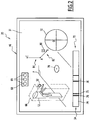
- FIG. 1 illustrates a video surveillance system 10 according to the invention, hereinafter system 10.
- the system 10 is intended for monitoring a given installation, for example a building, a factory, a warehouse, a public transport installation such as for example an airport or a station, etc.
- the system 10 comprises a first and a second equipment 12, 13, a first, a second and a third camera 14, 16, 18 respectively, a first and a second monitoring station 20, 22, hereinafter positions 20, 22, and a management server 24, hereinafter server 24.
- the equipment 12, 13 are remotely controllable.
- the equipment 12, 13 are connected to the server 24.
- the equipment 12, 13 are equipment of the installation that the system 10 makes it possible to monitor.
- the equipment 12, 13 are turnstiles.
- the equipment 12, 13 are one of the following: an access door, a programmable display panel, a machine tool, or any other device of the considered installation whose remote control is feasible and being in the field of view of at least one of the cameras 14, 16, 18.
- the system 10 comprises one or more remote-controllable equipment 12, 13 connected to the server 24.
- the cameras 14, 16, 18 are connected to at least one monitoring station 20, 22.
- the first camera 14 is connected to the first station 20, and the second and third cameras 16, 18 are connected to the second station 22.
- Each camera 14, 16, 18 has a field of view 26, 28, 30 and is adapted to deliver to the station 20, corresponding 22 of the images 31 (FIG. Figure 2 ) each corresponding to a shooting of its field of view 26, 28, 30.
- the cameras 14, 16, 18 are steerable, that is, they are adapted to scroll their field of view 26, 28, 30 respectively.
- the set of possible fields of view 26, 28, 30 of a camera 14, 16, 18 forms an observation field 32, 34, 36 of the camera.
- the field of view 32, 34, 36 corresponds in practice to all the elements of the installation that the camera 14, 16, 18 corresponding is suitable to observe.
- the observation fields 32, 34 of the first and second cameras 14, 16 have a first common portion 38, and the observation fields 34, 36 of the second and third cameras 16, 18 have a second common portion 40 .
- the first equipment 12 is located in the observation field 32 of the first camera 14 and the second equipment 13 is located in the first common part 38.
- cameras 14, 16, 18 are PTZ type dome cameras, English acronym for "Pan Tilt Zoom", which means “Pan Tilt Magnification”.
- the field of view 26, 28, 30 of the cameras 14, 16, 18 is thus pivotable about two orthogonal, hereinafter panoramic axis 42 and inclination axis 44 (in dashed lines on the Figure 1 and shown only for the first camera 14) and is movable in depth, i.e., the cameras are capable of achieving magnifications and narrowing. This allows the cameras to have a field of observation 32, 34, 36 of maximum size and to be able to change the magnification level of the elements of the installation.
- Each camera 14, 16, 18 is configured to provide each station 20, 22 to which it is connected information representative of its current orientation.
- the cameras 14, 16, 18 thus provide information representative of their current orientation along their panoramic axis 42 and their inclination axis 44, as well as their current magnification level.
- the monitoring stations 20, 22 are connected to the server 24 and to at least one of the cameras 14, 16, 18.
- Each station 20, 22 comprises display means 46, input means 48 and a processing unit 50.
- the display means 46 comprise a screen adapted to display the images 31 provided by the cameras 14, 16, 18 connected to the corresponding station 20, 22.
- the input means 48 are suitable for allowing an operator to enter data to interact with the display means 46 and the processing unit 50, and in particular with a graphical interface generated by the processing unit 50 on the means. 46.
- the input means 48 comprise a keyboard (not shown) and a mouse associated with a cursor 52 viewable on the display means 46 and that the operator of the station 20, 22 corresponding moves on the means of display. display 46 by moving the mouse. The operator interacts for example with an element displayed on the display means 46 by positioning the cursor 52 above the element and then actuating the mouse.
- the display means 46 and the gripping means 48 are adapted to allow the operator to interact with the display means 46 tactilely.
- the processing unit 50 is able to drive the display means 46 and the input means 48 and to communicate with the server 24.
- the processing unit 50 is suitable for displaying on the means for displaying images 31 provided by the associated cameras 14, 16, 18 and generating a graphic interface 54 superimposed on the images 31.
- the processing unit 50 is connected to the cameras 14, 16, 18 associated and comprises a processor and a memory (not shown) comprising software necessary for the conventional operation of the processing unit 50.
- the processing unit 50 includes a graphical interface generation module 56 configured to generate the graphical interface 54, which is described in more detail below.
- the GUI module 56 includes an augmented reality module 58 and a control module 60.
- the augmented reality module 58 comprises a calculation module 62 configured to transpose the position of the points of the observation field 32, 34, 36 of the cameras 14, 16, 18 associated with the station 20, 22 corresponding to a position on the means of 46, and vice versa.
- the calculation module 62 is configured to determine the position of the points of the observation field 32, 34, 36 from their position on the images 31 displayed on the display means 46 and parameters provided by the camera. corresponding and indicating the orientation of the camera, and to determine the position of the points on the display means 46 from the corresponding position in the field of view 32, 34, 36 and the parameters provided by the camera.
- the calculation module 62 thus makes it possible to establish a correspondence between the position of the points of the observation fields 32, 34, 36 and the position of the points of the images 31 displayed on the display means 46. As will be seen from FIG. subsequently, this makes it possible to remanently associate the position of an element of the graphic interface 54 with the position of a point in the field of view of one or more cameras 14, 16, 18.
- the augmented reality module 58 comprises a rendering module 64 configured to generate, on the display means 46, the graphic interface 54 superimposed on the images 31 from data provided by the calculation module 62, by the cameras 14, 16, 18 and the server 24.
- the augmented reality module 58 controls the display of the graphical interface 54 from the data it receives from the other organs of the system 10 which he is connected to.
- the control module 60 is configured to support the interactions of the input means 48 with the graphical interface 54.
- control module 60 is configured to detect the data input by the operator via an interaction of the input means 48 with the graphic interface 54, in particular via the cursor 52 displayed on the display means 46, and transmit the corresponding information to the organ of the system 10 concerned, such as the camera 14, 16, 18, the equipment 12, 13 that the operator wishes to control or the augmented reality module 58.
- the data are intended for a camera or equipment 12, 13, the information is conveyed either directly to the corresponding camera 14, 16, 18, or to the equipment 12, 13 via the server 24.
- the server 24 is able to allow the communication of the monitoring stations 20, 22 with each other and with the equipment 12, 13, as well as to supply configuration data of the system 10 to the stations 20, 22.
- the configuration data include data relating to the equipment 12, 13, or to virtual objects whose display is made on the display means 46 of the stations 20, 22. This is described in more detail in the following. .
- the graphical interface 54 will now be described in more detail with reference to the Figures 1 is 2.
- the graphic interface 54 of the stations 20, 22 includes interface elements superimposed on the images 31 and through which the operator interacts with the equipment 12, 13 or the cameras 14, 16, 18 associated with the monitoring station 20 , 22 from which he operates.
- the graphical interface 54 is configured to display an identification element 66 associated with the equipment 12, 13.
- the identification element 66 is directly displayed on the associated equipment 12, 13 so that the identification element 66 is superimposed on the equipment 12, 13 in the images 31.
- the identification element 66 is a schematic representation of the equipment 12, 13.
- the identification element 66 is associated with a point of the equipment 12, 13 so that it moves with the equipment 12, 13 when the field of view 26, 28, 30 of the camera 14, 16 , 18 corresponding is changed due to a movement of the camera according to one or more of its degrees of freedom.
- the identification element of the equipment 12 is a partially opaque parallelepiped in which the equipment 12 is inscribed.
- the identification element 66 is selectable via the input means 48, for example via the cursor 52.
- the graphical interface 54 is configured to display an equipment control interface 68, hereinafter control interface 68, for the control of the equipment 12.
- control interface 68 is selectively activatable by the selection of the corresponding identification element 66 via the input means 48.
- the control interface 68 comprises control buttons 69 respectively associated with a preconfigured action of the equipment 12, 13 associated, such as for example the opening of the equipment 12, 13 if it is a door, its rotation if This is a turnstile, turning it on, turning it off, displaying a preprogrammed message if it is a programmable display panel, etc.
- control interface 68 also comprises means for setting the identification element 66, for example to parameterize the color of the identification element, its opacity, etc.
- the graphical interface 54 comprises a dedicated control interface 68 for each device 12.
- the graphic interface 54 comprises a control interface 68 dedicated to several pieces of equipment 12, 13 and via which the operator can control the corresponding equipment items 12, 13.
- the display of the control interface 68 is for example made for a predefined duration after the selection of the identification element 66, or until a new operation of the input means 48 by the operator.
- the graphic interface 54 is configured to display a camera control interface 70, hereinafter camera interface 70, for controlling the orientation of the camera 14, 16, 18 whose images 31 are displayed on the display means 46.
- the camera interface 70 comprises a virtual joystick 72 operable via the cursor 52 for the reorientation of the camera 14, 16, 18 in two or more degrees of freedom of the camera simultaneously.
- the camera interface 70 comprises an orientation bar 74 representing all of the possible orientations of the camera 14, 16, 18 according to one of its degrees of freedom, for example around its panoramic axis 42, as well as the current orientation of the camera, represented by an orientation key 75 hatched on the Figure 2 .
- Each location of the orientation bar 74 corresponds to a given orientation of the camera 14, 16, 18 according to the degree of freedom associated.
- Each location of the orientation bar 74 is selectable via the input means 48, either directly or by moving the orientation key 75. Selecting a location of the orientation bar triggers the camera recall 14, 16, 18 corresponding in the associated orientation.
- orientation bar 74 only a portion of the locations of the orientation bar 74 is selectable to trigger the recall of the corresponding camera 14, 16, 18 in the associated orientation.
- the camera interface 70 includes selectively activatable return buttons 76 for controlling the recall of the camera 14, 16, 18 in a preconfigured orientation.
- the return keys 76 are for example associated with orientations of the camera 14, 16, 18 which correspond to fields of view 26, 28, 30 in which equipment 12, 13 is located. In the embodiment of the Figure 1 , the return keys 76 are located on the orientation bar 74. Alternatively, the return keys 76 are located on the virtual joystick 72, or are arranged in a dedicated location of the graphical interface 54.
- the graphic interface 54 is also configured to display virtual objects 70 respectively associated with a particular point of the field of view 32, 34, 36 of the camera 14, 16, 18 whose images 31 are displayed on the screens. display means 46.
- the virtual objects 78 are included in the group consisting of: a translucent geometric shape, an opaque geometric shape, a set of alphanumeric characters, an icon or a symbol, for example signaling.
- the Figure 2 illustrates a virtual object 78 associated with a point of the field of view 32 of the first camera 14 and represented by a cross.
- the virtual object 78 is a translucent octagon.
- the virtual objects 78 are generated by the graphical interface generation module 56 of the monitoring stations 20, 22 from the configuration data provided by the server 24. This is described in more detail in the following.
- the cameras 14, 16, 18 provide each station 20, 22 to which they are connected the shots they take from their field of view 26, 28, 30.
- the processing unit 50 stations 20, 22 carries out the display of a temporal sequence of the corresponding images 31 on the corresponding display means 46.
- the operator of the first station 20 sees a temporal sequence of images 31 delivered by the first camera 14 and on which the equipment 12 appears.
- the operator of the second station 22 can switch selectively between the images 31 provided by one and the other of the second and third cameras 16, 18, for example by means of a key (not shown) on the input means 48 or via an element (not shown) of the graphical interface 54 provided for this purpose.
- the operator displays a sequence of images 31 on which the second equipment 13 appears.
- the graphic interface generation modules 54 of the stations 20, 22 generate and display the corresponding graphic interface 54 on the associated display means 46 and superimposed on the images 31.
- the processing unit 50 receives the configuration data from the server 24, for example at a regular frequency.
- the data contains the information relating to the identification elements 66 of the equipment 12, 13 and virtual objects 78 located in the field of view 32, 34, 36 of at least one of the cameras 14, 16, 18 to which the station 20, 22 corresponding is connected.
- the augmented reality module 58 processes the data, generates the identification elements 66 and the virtual objects 78, and controls the display on the graphical interface 54. If the field of view whose images 31 are displayed does not contain point with which is associated an identification element 66 or a virtual object 78, no identification element 66 or virtual object 78 is therefore viewable on the corresponding display means 46.
- the augmented reality module 58 updates the display of the identification elements 66 and the virtual objects 78 when the orientation of the camera 14, 16, 18 whose images 31 are displayed is modified so that the elements identification 66 and virtual objects 78 behave as if they were physically present in the corresponding field of view 32, 34, 36.
- the calculation module 62 determines the position on the images 31 of the points of the observation field or fields 32, 34, 36 corresponding to which are associated an identification element 66 or a virtual object 78, and the module of rendering 64 controls the display of the graphical interface 54 accordingly.
- the operator selects the corresponding identification element 66 via the cursor 52.
- the interaction of the input means 48 with the graphic interface 54 is detected by the control module 60 This triggers the display of the control interface 68 associated with the equipment 12, 13 and via which the operator selects the command which he wishes the equipment to carry out via the control buttons 69. selected command, the corresponding information is detected by the control module 60 and relayed to the server 24, which transmits it to the equipment 12, 13 recipient.
- the equipment 12, 13 then executes the command.
- the operator uses the camera interface 70. For example, he modifies the orientation of the camera 14 according to two degrees simultaneously by using the virtual joystick 72, or selects a preconfigured orientation of the camera via a recall key 76. The operator can also scroll the orientation key 75 along the orientation bar 74, or modify the position of the orientation key 75 by positioning the cursor 52 on the orientation bar 74 and by actuating the input means 46. These interactions are detected by the corresponding control module 60, which relay the corresponding command directly to the camera 14, 16, 18 recipient. The camera then changes its orientation accordingly.
- the operator can create a virtual object 78 and associate the virtual object 78 with a particular point in the field of view 26, 28, 30 of one of the cameras 14, 16, 18 to which the item 20 is connected.
- the operator selects a particular point of the image 31, for example by pointing the cursor 52 on the point in question and by actuating a particular key of the input means 48, such as a button particular of the mouse.
- the point thus defined corresponds to the point at which the virtual object 78 will be associated.
- the operator then defines the type and the shape of the virtual object 78, for example by selecting the virtual object 78 from a list of virtual object models 78, by drawing a closed form via the cursor 52 or by entering the Corresponding alphanumeric characters via the input means 58.
- the virtual object 78 Once the virtual object 78 has been selected, drawn or inputted, its superimposition on the images 31 is carried out by the augmented reality module 58 of the corresponding station 20, 22, the associated data. to the virtual object 78 are sent to the server 24 and the first operating mode is disabled.
- the server 24 stores the data of the virtual objects 78 generated via the stations 20, 22 and communicates them to the stations 20, 22 which are connected to at least one camera whose observation field 32, 34, 36 comprises the point at which the virtual object 78 is associated.
- a virtual object 78 associated with a point of the first common portion 38 will be viewable on the display means 46 of the first station 20 as the second station 22 when the point associated with the virtual object 78 will be in the field of view 26, 28 of the corresponding camera 14, 16, even if the second station 20 does not have the first mode of operation, for example because it is disabled.
- the virtual objects 78 are adapted to be deleted from the stations 20, 22, for example by means of a key of the input means provided for this purpose, or by interaction with the virtual object 78 in question.
- the operator extracts from the images 31 geometrical information 80 relating to points of the fields of view 26, 28, 30 of the camera 14, 16, 18 whose images 31 are displayed on the means of view. display 46.
- the geometric information 80 is determined by assuming that the positions in the field of view 32, 34, 36 corresponding and designated by the cursor 52 all belong to a predetermined horizontal plane P or all belong to a orthogonal to the horizontal plane P.
- the horizontal plane P is the ground plane of the installation.
- the operator actuates a particular button of the input means 48, or a key provided for this purpose on the graphical interface 54.
- the operator extracts geometric information 80 from the images 31 by positioning the cursor 52 on a point of the display means 46 (point A on the Figure 2 ) corresponding to a position in the corresponding field of view 32, 34, 36 and about which it wishes to obtain geometric information 80, and actuates the input means 48.
- This freezes the position of the point A and triggers the display a segment between the point A and the point of the display means 46 to which the cursor 52 points (point B in horizontal mode 82 and point C in vertical mode 84), as well as the display of one or more information geometric 80.
- the geometric information 80 includes an indication of the distance in the field of view 32, 34, 36 between the point of the field of view corresponding to point A and the position in the corresponding field of view of point B or C.
- the distance between the points A and B or C is determined by the calculation module 62 of the station 20, 22, which transposes the position on the display means 46 of the points A and B or C in positions in the field of view 32, 34, 36 and calculates the distance between these positions.
- the vertical mode 84 thus makes it possible to determine the height relative to the horizontal plane P of the objects that can be viewed on the images 31, and the horizontal mode 82 makes it possible to measure the distance in the plane P between two objects.
- the geometrical information 80 also includes or alternatively an indication of the speed of displacement of the point of field of view 26, 28, 30 corresponding to the point B or C.
- the operator designates with the point A to the object of which it wishes to measure the speed of displacement then points again the cursor 52 on the object but on a subsequent image 31, and actuates a second time the input means 48.
- the calculation module 62 then calculates the speed of the object from the positions of the point A and the point B or C thus fixed and the respective dates of the images 31 displayed at the respective instants where the operator has fixed the point A, respectively the point B or C.
- one or more of the stations 20, 22 implement an automatic motion detection algorithm such that geometric information 80 comprising a speed indication in the horizontal plane P is displayed on the associated graphic interface 54 for all or part of the objects. moving in the field of view 26, 28, 30 corresponding, or for all or part of the objects having certain predetermined characteristics, for example size or color.
- the operator switches between the vertical mode 84 and the horizontal mode 82 via a key provided for this purpose on the input means 48 or on the graphical interface 54, or by keeping a touch of the means of seizure 48 depressed.
- the display of identification elements 66 associated with the equipment 12, 13 on the graphic interface 54 of the stations facilitates the identification of the equipment 12, 13.
- the display of the identification elements 66 superimposed on the equipment 12, 13 facilitates the location of the equipment 12, 13 on the images 31, which further improves the ergonomics of the stations 20, 22.
- the graphic interface 54 of the stations makes it possible to remotely control the equipment 12, 13 directly via the display means 46 and by means of the same graphic interface 54 via which it displays the images 31, which improves the ergonomics of the stations 20, 22 compared to a scenario in which the equipment 12, 13 are remotely controlled by a dedicated interface.
- the control of the equipment 12, 13 via the control interfaces 68 activated by the selection of associated identification elements 66 reduces the risks of carrying out the control of the bad equipment and improves the response time of the operator because he does not need to divert his attention from the pictures.
- the first mode of operation allows the various operators of the system 10 to share graphic information and in the context of images 31 provided by the cameras.
- it makes it possible to centrally configure the areas of privacy masking of the installation that the system 10 makes it possible to monitor, which, in known video surveillance systems, must be made specifically for each camera.
- the masking areas may for example be configured as opaque virtual objects 78 whose shape is suitably chosen.
- the second mode of operation allows operators to obtain geometric information on the elements of the monitored installation directly via the monitoring stations, and this in a simple manner and without prior knowledge of the installation.
- the server 24 makes it possible to centralize the configuration of the stations 20, 22 in general, which facilitates the operation of adding or deleting a station to the system 10 and makes the latter more flexible.
- the stations 20, 22 are adapted to simultaneously display the images 31 provided by several or all the cameras to which they are connected, for example by dedicating to each camera 14, 16, 18 a portion of the display means 46.
- the graphic interface generating module 56 of the stations 20, 22 generates as many graphic interfaces 54 as there are cameras whose images 31 are displayed on the display means 46, the operation each graphical interface 54 being the same as that described above.
Claims (10)
- Videoüberwachungssystem aufweisend :- mindestens eine Kamera (14, 16, 18), welche ein Beobachtungsfeld (32, 34, 36) aufweist und welche geeignet ist, Bilder (31) aus ihrem Beobachtungsfeld zu liefern (32, 34, 36),- mindestens ein Gerät (12, 13), welches fernsteuerbar ist, und welches sich in dem Beobachtungsfeld (32, 34, 36) der Kamera (14, 16, 18) befindet,- mindestens eine Überwachungsstation (20, 22), welche an mindestens eine Kamera (14, 16, 18) angeschlossen ist und welche Eingabemittel (48), Anzeigemittel (46) zum Anzeigen einer zeitlichen Abfolge von Bildern (31), welche durch die oder jede entsprechende Kamera (14, 16, 18) geliefert werden, und ein Schnittstellenerzeugungsmodul (56) aufweist, welches konfiguriert ist, eine grafische Benutzeroberfläche (54) zu erzeugen, welche in den auf den Anzeigemitteln (46) angezeigten Bildern (31) eingeblendet wird, dadurch gekennzeichnet, dass das Schnittstellenerzeugungsmodul (56) der oder jeder Überwachungsstation (20, 22) konfiguriert ist, durch die grafische Benutzeroberfläche (54) ein Identifizierungselement (66) des Geräts (12, 13), welches direkt auf dem Gerät (12, 13) eingeblendet wird, zu erzeugen und anzuzeigen, so dass das Identifizierungselement (66) auf dem Gerät (12, 13) in den Bildern (31) eingeblendet wird, so dass das Identifizierungselement (66) über die Eingabemittel (48) selektiv aktivierbar ist, um die Anzeige auf der grafischen Benutzeroberfläche (54) einer Steuerschnittstelle (68) für die Fernsteuerung mindestens eines Geräts (12, 13) auszulösen, und dass das Überwachungssystem Steuermittel (60) für die Steuerung des oder jedes Geräts (12, 13) abhängig von durch einen Benutzer über die Steuerschnittstelle (68) eingegebenen Informationen aufweist.
- Videoüberwachungssystem nach Anspruch 1, dadurch gekennzeichnet, dass mindestens eine Überwachungsstation (20, 22) einen zweiten Betriebsmodus aufweist, bei dem die grafische Benutzeroberfläche (54) der Überwachungsstation (20, 22) eingerichtet ist, die Anzeige von geometrischen Informationen (80) bereitzustellen, welche den Abstand in dem Beobachtungsfeld (32, 34, 36) der Kamera (14, 16, 18), deren Bilder (31) auf den Anzeigemitteln (46) angezeigt werden, zwischen zwei Punkten (A, B, C) der Anzeigemittel (46) und / oder die Bewegungsgeschwindigkeit eines Objekts in dem Beobachtungsfeld (32, 34, 36) der Kamera (14, 16, 18), deren Bilder (31) auf den Anzeigemitteln angezeigt werden (46), aufweisen.
- Videoüberwachungssystem nach Anspruch 2, dadurch gekennzeichnet, dass der zweite Betriebsmodus einen horizontalen Betriebsmodus (82), bei dem die geometrischen Informationen (80) in einer vorbestimmten horizontalen Ebene (P) des Beobachtungsfelds (32, 34, 36) der Kamera (14, 16, 18) projiziert werden, deren Bilder (31) auf den Anzeigemitteln (46) angezeigt werden, und einen vertikalen Betriebsmodus (84), bei dem die geometrischen Informationen auf einer zu der horizontalen Ebene (P) orthogonalen Linie projiziert werden, aufweist.
- Videoüberwachungssystem nach einem der vorhergehenden Ansprüche, dadurch gekennzeichnet, dass die Überwachungsstation (20, 22) einen ersten Betriebsmodus aufweist, bei dem die assoziierte grafische Benutzeroberfläche (54) für die Erstellung von virtuellen Objekten (78) und die Zuordnung jedes virtuellen Objekts (78) zu einer Position des Beobachtungsfelds (32, 34, 36) einer Kamera (14, 16, 18) eingerichtet ist, an welche die Überwachungsstation angeschlossen ist, so dass ein virtuelles Objekt (78) auf den Bildern (31) angezeigt wird, welche durch die Kamera (14, 16, 18) geliefert werden und in denen die mit dem virtuellen Objekt (78) assoziierte Position des Beobachtungsfelds (32, 34, 36) angezeigt wird.
- Videoüberwachungssystem nach Anspruch 4, dadurch gekennzeichnet, dass jedes virtuelle Objekt (78) auf den Bildern (31) angezeigt wird, welche von jeder der mit der Überwachungsstation (20, 22) angeschlossenen Kameras (14, 16, 18) geliefert werden, und deren Beobachtungsfeld (32, 34, 36) die Position, der das virtuelle Objekt (78) zugeordnet ist, aufweist.
- Videoüberwachungssystem nach Anspruch 4 oder 5, dadurch gekennzeichnet, dass jedes virtuelle Objekt (78) auf den Bildern (31) angezeigt wird, welche von jeder der Kameras (14, 16, 18) des Videoüberwachungssystems (10) geliefert werden und deren Beobachtungsfeld (32, 34, 36) die Position, der das virtuelle Objekt (78) zugeordnet ist, aufweist.
- Überwachungssystem nach einem der Ansprüche 4 bis 6, dadurch gekennzeichnet, dass ein virtuelles Objekt (78) in der Gruppe enthalten ist, bestehend aus: einer lichtdurchlässigen geometrischen Form, einer lichtundurchlässigen geometrischen Form, einer Menge von alphanumerischen Zeichen, einer Ikone oder einem Symbol.
- Überwachungssystem nach einem der vorhergehenden Ansprüche, dadurch gekennzeichnet, dass mindestens eine Kamera (14, 16, 18) einstellbar ist, wobei die grafische Benutzeroberfläche (54) mindestens eine der an die Kamera angeschlossenen Überwachungsstationen (20, 22) mindestens eine selektiv betreibbare Rücklauftaste (76) aufweist, um den Rücklauf der Kamera in einer vorbestimmten Ausrichtung auszulösen.
- Überwachungssystem nach einem der vorhergehenden Ansprüche, dadurch gekennzeichnet, dass mindestens eine Kamera (14, 16, 18) einstellbar ist, wobei die grafische Benutzeroberfläche (54) mindestens eine der an die Kamera angeschlossenen Überwachungsstationen (20, 22) eine Ausrichtungsstange (74) aufweist, welche die Gesamtheit der möglichen Ausrichtungen der Kamera gemäß dem oder einem der Freiheitsgrade der Kamera (14, 16, 18) repräsentiert.
- Videoüberwachungssystem nach Anspruch 9, dadurch gekennzeichnet, dass die Ausrichtungsstange (74) eine oder mehrere wählbare Stellen aufweist, wobei die Auswahl einer wählbaren Stelle der Ausrichtungsstange (74) konfiguriert ist, den Rücklauf der Kamera (14, 16, 18) in der entsprechenden Orientierung auszulösen.
Applications Claiming Priority (1)
| Application Number | Priority Date | Filing Date | Title |
|---|---|---|---|
| FR1301297A FR3006842B1 (fr) | 2013-06-06 | 2013-06-06 | Systeme de videosurveillance |
Publications (2)
| Publication Number | Publication Date |
|---|---|
| EP2811465A1 EP2811465A1 (de) | 2014-12-10 |
| EP2811465B1 true EP2811465B1 (de) | 2016-05-11 |
Family
ID=49378316
Family Applications (1)
| Application Number | Title | Priority Date | Filing Date |
|---|---|---|---|
| EP14171543.3A Active EP2811465B1 (de) | 2013-06-06 | 2014-06-06 | Videoüberwachungssystem |
Country Status (5)
| Country | Link |
|---|---|
| EP (1) | EP2811465B1 (de) |
| ES (1) | ES2586714T3 (de) |
| FR (1) | FR3006842B1 (de) |
| MX (1) | MX336305B (de) |
| PT (1) | PT2811465T (de) |
Cited By (1)
| Publication number | Priority date | Publication date | Assignee | Title |
|---|---|---|---|---|
| WO2019075381A3 (en) * | 2017-10-13 | 2019-06-13 | J. Brasch Co., Llc | Assistive technology for operating nursing homes and other health care facilities |
Families Citing this family (1)
| Publication number | Priority date | Publication date | Assignee | Title |
|---|---|---|---|---|
| CN113124986A (zh) * | 2021-04-15 | 2021-07-16 | 天津港集装箱码头有限公司 | 汽车衡远程虚拟仿真方法及仿真系统 |
Family Cites Families (4)
| Publication number | Priority date | Publication date | Assignee | Title |
|---|---|---|---|---|
| US7497376B2 (en) * | 2004-06-08 | 2009-03-03 | Donald M. Landwirth | Business method of implementing an automated vault machine |
| WO2009122416A2 (en) * | 2008-04-02 | 2009-10-08 | Evt Technologies Ltd. | Object content navigation |
| US9398231B2 (en) * | 2010-03-15 | 2016-07-19 | Omron Corporation | Surveillance camera terminal |
| AU2011202555B2 (en) * | 2011-05-31 | 2013-07-18 | Canon Kabushiki Kaisha | Multi-view alignment based on fixed-scale ground plane rectification |
-
2013
- 2013-06-06 FR FR1301297A patent/FR3006842B1/fr not_active Expired - Fee Related
-
2014
- 2014-06-06 ES ES14171543.3T patent/ES2586714T3/es active Active
- 2014-06-06 MX MX2014006806A patent/MX336305B/es unknown
- 2014-06-06 PT PT141715433T patent/PT2811465T/pt unknown
- 2014-06-06 EP EP14171543.3A patent/EP2811465B1/de active Active
Cited By (2)
| Publication number | Priority date | Publication date | Assignee | Title |
|---|---|---|---|---|
| WO2019075381A3 (en) * | 2017-10-13 | 2019-06-13 | J. Brasch Co., Llc | Assistive technology for operating nursing homes and other health care facilities |
| US11083419B2 (en) | 2017-10-13 | 2021-08-10 | J. Brasch Co., Llc | Assistive technology for operating nursing homes and other health care facilities |
Also Published As
| Publication number | Publication date |
|---|---|
| ES2586714T3 (es) | 2016-10-18 |
| MX2014006806A (es) | 2014-12-05 |
| EP2811465A1 (de) | 2014-12-10 |
| MX336305B (es) | 2016-01-14 |
| PT2811465T (pt) | 2016-08-16 |
| FR3006842A1 (fr) | 2014-12-12 |
| FR3006842B1 (fr) | 2015-07-17 |
Similar Documents
| Publication | Publication Date | Title |
|---|---|---|
| KR102038639B1 (ko) | 증강 현실 및/또는 가상 현실에서의 터치 스크린 호버 검출 | |
| KR101803168B1 (ko) | 실질 세계 객체 조작에 기초한 데이터 조작 | |
| CN103959135B (zh) | 用于输入检测的方法和系统 | |
| AU2015301620B2 (en) | Remote expert system | |
| US20190279424A1 (en) | Collaborative augmented reality system | |
| EP2996088B1 (de) | Verfahren zur gleichzeitigen Visualisierung von Oberfächendaten und Panoramabilder-Daten der gleichen Umgebung | |
| WO2014021004A1 (ja) | 画像処理システム、画像処理方法、及びプログラム | |
| KR20130112061A (ko) | 자연스러운 제스처 기반 사용자 인터페이스 방법 및 시스템 | |
| KR20050000276A (ko) | 감시 카메라 제어용 가상 조이스틱 시스템 및 제어 방법 | |
| WO2015102854A1 (en) | Assigning virtual user interface to physical object | |
| MXPA06013936A (es) | Metodo y sistema para monitoreo de seguridad de area extensa, manejo de sensores y conocimiento situacional. | |
| WO2014143347A1 (en) | Interfaces for security system control | |
| WO2011098465A1 (fr) | Procede de fonctionnement d'un dispositif de commande d'equipements domotiques | |
| FR2963186A1 (fr) | Systeme de videosurveillance et procede de configuration de ce systeme | |
| WO2011059659A1 (en) | System and method for annotating video with geospatially referenced data | |
| FR3005173A1 (fr) | Procede d'interaction dans un cockpit d'aeronef entre un pilote et son environnement | |
| EP2811465B1 (de) | Videoüberwachungssystem | |
| FR3039919A1 (fr) | Suivi d’une cible dans un reseau de cameras | |
| FR2981470A1 (fr) | Dispositif adapte pour la mise en oeuvre d'un systeme de supervision et de controle | |
| WO2023046902A1 (fr) | Systeme d'interface homme-machine | |
| US11455047B1 (en) | Computer mouse with integrated joystick and a plurality of interface circuits | |
| WO2022269887A1 (ja) | ウェアラブル端末装置、プログラムおよび画像処理方法 | |
| JP2009075480A (ja) | 筒状表示装置,筒状入力装置及び送出制御装置 | |
| FR3127597A1 (fr) | Systeme d’interface homme-machine | |
| FR3121251A3 (fr) | Procédé et système informatisés de navigation en réalités virtuelles et programme d’ordinateur |
Legal Events
| Date | Code | Title | Description |
|---|---|---|---|
| PUAI | Public reference made under article 153(3) epc to a published international application that has entered the european phase |
Free format text: ORIGINAL CODE: 0009012 |
|
| 17P | Request for examination filed |
Effective date: 20140606 |
|
| AK | Designated contracting states |
Kind code of ref document: A1 Designated state(s): AL AT BE BG CH CY CZ DE DK EE ES FI FR GB GR HR HU IE IS IT LI LT LU LV MC MK MT NL NO PL PT RO RS SE SI SK SM TR |
|
| AX | Request for extension of the european patent |
Extension state: BA ME |
|
| R17P | Request for examination filed (corrected) |
Effective date: 20150116 |
|
| RBV | Designated contracting states (corrected) |
Designated state(s): AL AT BE BG CH CY CZ DE DK EE ES FI FR GB GR HR HU IE IS IT LI LT LU LV MC MK MT NL NO PL PT RO RS SE SI SK SM TR |
|
| REG | Reference to a national code |
Ref country code: DE Ref legal event code: R079 Ref document number: 602014001851 Country of ref document: DE Free format text: PREVIOUS MAIN CLASS: G06T0019200000 Ipc: G08B0013196000 |
|
| GRAP | Despatch of communication of intention to grant a patent |
Free format text: ORIGINAL CODE: EPIDOSNIGR1 |
|
| RIC1 | Information provided on ipc code assigned before grant |
Ipc: G08B 13/196 20060101AFI20151007BHEP Ipc: H04N 5/272 20060101ALI20151007BHEP |
|
| GRAJ | Information related to disapproval of communication of intention to grant by the applicant or resumption of examination proceedings by the epo deleted |
Free format text: ORIGINAL CODE: EPIDOSDIGR1 |
|
| GRAP | Despatch of communication of intention to grant a patent |
Free format text: ORIGINAL CODE: EPIDOSNIGR1 |
|
| INTG | Intention to grant announced |
Effective date: 20151112 |
|
| INTG | Intention to grant announced |
Effective date: 20151125 |
|
| GRAS | Grant fee paid |
Free format text: ORIGINAL CODE: EPIDOSNIGR3 |
|
| GRAA | (expected) grant |
Free format text: ORIGINAL CODE: 0009210 |
|
| AK | Designated contracting states |
Kind code of ref document: B1 Designated state(s): AL AT BE BG CH CY CZ DE DK EE ES FI FR GB GR HR HU IE IS IT LI LT LU LV MC MK MT NL NO PL PT RO RS SE SI SK SM TR |
|
| REG | Reference to a national code |
Ref country code: GB Ref legal event code: FG4D Free format text: NOT ENGLISH |
|
| REG | Reference to a national code |
Ref country code: CH Ref legal event code: EP |
|
| REG | Reference to a national code |
Ref country code: AT Ref legal event code: REF Ref document number: 799197 Country of ref document: AT Kind code of ref document: T Effective date: 20160515 |
|
| REG | Reference to a national code |
Ref country code: IE Ref legal event code: FG4D Free format text: LANGUAGE OF EP DOCUMENT: FRENCH |
|
| REG | Reference to a national code |
Ref country code: DE Ref legal event code: R096 Ref document number: 602014001851 Country of ref document: DE |
|
| REG | Reference to a national code |
Ref country code: FR Ref legal event code: PLFP Year of fee payment: 3 |
|
| REG | Reference to a national code |
Ref country code: PT Ref legal event code: SC4A Ref document number: 2811465 Country of ref document: PT Date of ref document: 20160816 Kind code of ref document: T Free format text: AVAILABILITY OF NATIONAL TRANSLATION Effective date: 20160808 |
|
| REG | Reference to a national code |
Ref country code: NL Ref legal event code: FP |
|
| REG | Reference to a national code |
Ref country code: LT Ref legal event code: MG4D |
|
| REG | Reference to a national code |
Ref country code: ES Ref legal event code: FG2A Ref document number: 2586714 Country of ref document: ES Kind code of ref document: T3 Effective date: 20161018 |
|
| PG25 | Lapsed in a contracting state [announced via postgrant information from national office to epo] |
Ref country code: NO Free format text: LAPSE BECAUSE OF FAILURE TO SUBMIT A TRANSLATION OF THE DESCRIPTION OR TO PAY THE FEE WITHIN THE PRESCRIBED TIME-LIMIT Effective date: 20160811 Ref country code: LT Free format text: LAPSE BECAUSE OF FAILURE TO SUBMIT A TRANSLATION OF THE DESCRIPTION OR TO PAY THE FEE WITHIN THE PRESCRIBED TIME-LIMIT Effective date: 20160511 Ref country code: FI Free format text: LAPSE BECAUSE OF FAILURE TO SUBMIT A TRANSLATION OF THE DESCRIPTION OR TO PAY THE FEE WITHIN THE PRESCRIBED TIME-LIMIT Effective date: 20160511 |
|
| REG | Reference to a national code |
Ref country code: AT Ref legal event code: MK05 Ref document number: 799197 Country of ref document: AT Kind code of ref document: T Effective date: 20160511 |
|
| PG25 | Lapsed in a contracting state [announced via postgrant information from national office to epo] |
Ref country code: LV Free format text: LAPSE BECAUSE OF FAILURE TO SUBMIT A TRANSLATION OF THE DESCRIPTION OR TO PAY THE FEE WITHIN THE PRESCRIBED TIME-LIMIT Effective date: 20160511 Ref country code: SE Free format text: LAPSE BECAUSE OF FAILURE TO SUBMIT A TRANSLATION OF THE DESCRIPTION OR TO PAY THE FEE WITHIN THE PRESCRIBED TIME-LIMIT Effective date: 20160511 Ref country code: GR Free format text: LAPSE BECAUSE OF FAILURE TO SUBMIT A TRANSLATION OF THE DESCRIPTION OR TO PAY THE FEE WITHIN THE PRESCRIBED TIME-LIMIT Effective date: 20160812 Ref country code: HR Free format text: LAPSE BECAUSE OF FAILURE TO SUBMIT A TRANSLATION OF THE DESCRIPTION OR TO PAY THE FEE WITHIN THE PRESCRIBED TIME-LIMIT Effective date: 20160511 Ref country code: RS Free format text: LAPSE BECAUSE OF FAILURE TO SUBMIT A TRANSLATION OF THE DESCRIPTION OR TO PAY THE FEE WITHIN THE PRESCRIBED TIME-LIMIT Effective date: 20160511 |
|
| PG25 | Lapsed in a contracting state [announced via postgrant information from national office to epo] |
Ref country code: BE Free format text: LAPSE BECAUSE OF NON-PAYMENT OF DUE FEES Effective date: 20160630 |
|
| PG25 | Lapsed in a contracting state [announced via postgrant information from national office to epo] |
Ref country code: RO Free format text: LAPSE BECAUSE OF FAILURE TO SUBMIT A TRANSLATION OF THE DESCRIPTION OR TO PAY THE FEE WITHIN THE PRESCRIBED TIME-LIMIT Effective date: 20160511 Ref country code: CZ Free format text: LAPSE BECAUSE OF FAILURE TO SUBMIT A TRANSLATION OF THE DESCRIPTION OR TO PAY THE FEE WITHIN THE PRESCRIBED TIME-LIMIT Effective date: 20160511 Ref country code: EE Free format text: LAPSE BECAUSE OF FAILURE TO SUBMIT A TRANSLATION OF THE DESCRIPTION OR TO PAY THE FEE WITHIN THE PRESCRIBED TIME-LIMIT Effective date: 20160511 Ref country code: DK Free format text: LAPSE BECAUSE OF FAILURE TO SUBMIT A TRANSLATION OF THE DESCRIPTION OR TO PAY THE FEE WITHIN THE PRESCRIBED TIME-LIMIT Effective date: 20160511 Ref country code: SK Free format text: LAPSE BECAUSE OF FAILURE TO SUBMIT A TRANSLATION OF THE DESCRIPTION OR TO PAY THE FEE WITHIN THE PRESCRIBED TIME-LIMIT Effective date: 20160511 |
|
| REG | Reference to a national code |
Ref country code: DE Ref legal event code: R097 Ref document number: 602014001851 Country of ref document: DE |
|
| PG25 | Lapsed in a contracting state [announced via postgrant information from national office to epo] |
Ref country code: AT Free format text: LAPSE BECAUSE OF FAILURE TO SUBMIT A TRANSLATION OF THE DESCRIPTION OR TO PAY THE FEE WITHIN THE PRESCRIBED TIME-LIMIT Effective date: 20160511 Ref country code: PL Free format text: LAPSE BECAUSE OF FAILURE TO SUBMIT A TRANSLATION OF THE DESCRIPTION OR TO PAY THE FEE WITHIN THE PRESCRIBED TIME-LIMIT Effective date: 20160511 Ref country code: SM Free format text: LAPSE BECAUSE OF FAILURE TO SUBMIT A TRANSLATION OF THE DESCRIPTION OR TO PAY THE FEE WITHIN THE PRESCRIBED TIME-LIMIT Effective date: 20160511 |
|
| PLBE | No opposition filed within time limit |
Free format text: ORIGINAL CODE: 0009261 |
|
| STAA | Information on the status of an ep patent application or granted ep patent |
Free format text: STATUS: NO OPPOSITION FILED WITHIN TIME LIMIT |
|
| REG | Reference to a national code |
Ref country code: IE Ref legal event code: MM4A |
|
| PG25 | Lapsed in a contracting state [announced via postgrant information from national office to epo] |
Ref country code: MC Free format text: LAPSE BECAUSE OF FAILURE TO SUBMIT A TRANSLATION OF THE DESCRIPTION OR TO PAY THE FEE WITHIN THE PRESCRIBED TIME-LIMIT Effective date: 20160511 |
|
| 26N | No opposition filed |
Effective date: 20170214 |
|
| PG25 | Lapsed in a contracting state [announced via postgrant information from national office to epo] |
Ref country code: SI Free format text: LAPSE BECAUSE OF FAILURE TO SUBMIT A TRANSLATION OF THE DESCRIPTION OR TO PAY THE FEE WITHIN THE PRESCRIBED TIME-LIMIT Effective date: 20160511 Ref country code: IE Free format text: LAPSE BECAUSE OF NON-PAYMENT OF DUE FEES Effective date: 20160606 |
|
| REG | Reference to a national code |
Ref country code: FR Ref legal event code: PLFP Year of fee payment: 4 |
|
| REG | Reference to a national code |
Ref country code: CH Ref legal event code: PL |
|
| PG25 | Lapsed in a contracting state [announced via postgrant information from national office to epo] |
Ref country code: LI Free format text: LAPSE BECAUSE OF NON-PAYMENT OF DUE FEES Effective date: 20170630 Ref country code: CH Free format text: LAPSE BECAUSE OF NON-PAYMENT OF DUE FEES Effective date: 20170630 |
|
| PG25 | Lapsed in a contracting state [announced via postgrant information from national office to epo] |
Ref country code: HU Free format text: LAPSE BECAUSE OF FAILURE TO SUBMIT A TRANSLATION OF THE DESCRIPTION OR TO PAY THE FEE WITHIN THE PRESCRIBED TIME-LIMIT; INVALID AB INITIO Effective date: 20140606 |
|
| REG | Reference to a national code |
Ref country code: FR Ref legal event code: PLFP Year of fee payment: 5 |
|
| PG25 | Lapsed in a contracting state [announced via postgrant information from national office to epo] |
Ref country code: MT Free format text: LAPSE BECAUSE OF FAILURE TO SUBMIT A TRANSLATION OF THE DESCRIPTION OR TO PAY THE FEE WITHIN THE PRESCRIBED TIME-LIMIT Effective date: 20160511 Ref country code: LU Free format text: LAPSE BECAUSE OF NON-PAYMENT OF DUE FEES Effective date: 20160606 Ref country code: CY Free format text: LAPSE BECAUSE OF FAILURE TO SUBMIT A TRANSLATION OF THE DESCRIPTION OR TO PAY THE FEE WITHIN THE PRESCRIBED TIME-LIMIT Effective date: 20160511 Ref country code: MK Free format text: LAPSE BECAUSE OF FAILURE TO SUBMIT A TRANSLATION OF THE DESCRIPTION OR TO PAY THE FEE WITHIN THE PRESCRIBED TIME-LIMIT Effective date: 20160511 Ref country code: IS Free format text: LAPSE BECAUSE OF FAILURE TO SUBMIT A TRANSLATION OF THE DESCRIPTION OR TO PAY THE FEE WITHIN THE PRESCRIBED TIME-LIMIT Effective date: 20160511 |
|
| PG25 | Lapsed in a contracting state [announced via postgrant information from national office to epo] |
Ref country code: BG Free format text: LAPSE BECAUSE OF FAILURE TO SUBMIT A TRANSLATION OF THE DESCRIPTION OR TO PAY THE FEE WITHIN THE PRESCRIBED TIME-LIMIT Effective date: 20160511 |
|
| PG25 | Lapsed in a contracting state [announced via postgrant information from national office to epo] |
Ref country code: AL Free format text: LAPSE BECAUSE OF FAILURE TO SUBMIT A TRANSLATION OF THE DESCRIPTION OR TO PAY THE FEE WITHIN THE PRESCRIBED TIME-LIMIT Effective date: 20160511 Ref country code: TR Free format text: LAPSE BECAUSE OF FAILURE TO SUBMIT A TRANSLATION OF THE DESCRIPTION OR TO PAY THE FEE WITHIN THE PRESCRIBED TIME-LIMIT Effective date: 20160511 |
|
| P01 | Opt-out of the competence of the unified patent court (upc) registered |
Effective date: 20230516 |
|
| PGFP | Annual fee paid to national office [announced via postgrant information from national office to epo] |
Ref country code: PT Payment date: 20230517 Year of fee payment: 10 Ref country code: NL Payment date: 20230525 Year of fee payment: 10 Ref country code: IT Payment date: 20230608 Year of fee payment: 10 Ref country code: FR Payment date: 20230622 Year of fee payment: 10 Ref country code: DE Payment date: 20230613 Year of fee payment: 10 |
|
| PGFP | Annual fee paid to national office [announced via postgrant information from national office to epo] |
Ref country code: GB Payment date: 20230620 Year of fee payment: 10 Ref country code: ES Payment date: 20230706 Year of fee payment: 10 |