EP2811465B1 - Video surveillance system - Google Patents
Video surveillance system Download PDFInfo
- Publication number
- EP2811465B1 EP2811465B1 EP14171543.3A EP14171543A EP2811465B1 EP 2811465 B1 EP2811465 B1 EP 2811465B1 EP 14171543 A EP14171543 A EP 14171543A EP 2811465 B1 EP2811465 B1 EP 2811465B1
- Authority
- EP
- European Patent Office
- Prior art keywords
- camera
- images
- field
- observation
- video surveillance
- Prior art date
- Legal status (The legal status is an assumption and is not a legal conclusion. Google has not performed a legal analysis and makes no representation as to the accuracy of the status listed.)
- Active
Links
Images

Classifications
-
- H—ELECTRICITY
- H04—ELECTRIC COMMUNICATION TECHNIQUE
- H04N—PICTORIAL COMMUNICATION, e.g. TELEVISION
- H04N5/00—Details of television systems
- H04N5/222—Studio circuitry; Studio devices; Studio equipment
- H04N5/262—Studio circuits, e.g. for mixing, switching-over, change of character of image, other special effects ; Cameras specially adapted for the electronic generation of special effects
- H04N5/272—Means for inserting a foreground image in a background image, i.e. inlay, outlay
-
- G—PHYSICS
- G08—SIGNALLING
- G08B—SIGNALLING OR CALLING SYSTEMS; ORDER TELEGRAPHS; ALARM SYSTEMS
- G08B13/00—Burglar, theft or intruder alarms
- G08B13/18—Actuation by interference with heat, light, or radiation of shorter wavelength; Actuation by intruding sources of heat, light, or radiation of shorter wavelength
- G08B13/189—Actuation by interference with heat, light, or radiation of shorter wavelength; Actuation by intruding sources of heat, light, or radiation of shorter wavelength using passive radiation detection systems
- G08B13/194—Actuation by interference with heat, light, or radiation of shorter wavelength; Actuation by intruding sources of heat, light, or radiation of shorter wavelength using passive radiation detection systems using image scanning and comparing systems
- G08B13/196—Actuation by interference with heat, light, or radiation of shorter wavelength; Actuation by intruding sources of heat, light, or radiation of shorter wavelength using passive radiation detection systems using image scanning and comparing systems using television cameras
- G08B13/19678—User interface
- G08B13/19682—Graphic User Interface [GUI] presenting system data to the user, e.g. information on a screen helping a user interacting with an alarm system
-
- G—PHYSICS
- G08—SIGNALLING
- G08B—SIGNALLING OR CALLING SYSTEMS; ORDER TELEGRAPHS; ALARM SYSTEMS
- G08B13/00—Burglar, theft or intruder alarms
- G08B13/18—Actuation by interference with heat, light, or radiation of shorter wavelength; Actuation by intruding sources of heat, light, or radiation of shorter wavelength
- G08B13/189—Actuation by interference with heat, light, or radiation of shorter wavelength; Actuation by intruding sources of heat, light, or radiation of shorter wavelength using passive radiation detection systems
- G08B13/194—Actuation by interference with heat, light, or radiation of shorter wavelength; Actuation by intruding sources of heat, light, or radiation of shorter wavelength using passive radiation detection systems using image scanning and comparing systems
- G08B13/196—Actuation by interference with heat, light, or radiation of shorter wavelength; Actuation by intruding sources of heat, light, or radiation of shorter wavelength using passive radiation detection systems using image scanning and comparing systems using television cameras
- G08B13/19678—User interface
- G08B13/19689—Remote control of cameras, e.g. remote orientation or image zooming control for a PTZ camera
Definitions
- the invention lies in the field of video surveillance systems.
- the cameras of these systems provide images of their field of view at the monitoring station by means of which an operator realizes the actual monitoring of the installation.
- control of the equipment of the installation is generally carried out via a dedicated interface.
- the operator To control the equipment or equipment, the operator must then divide his attention between the images and the interface dedicated to the control of the equipment, which decreases the effectiveness of the monitoring and increases the reaction time of the operator to the events occurring in the supervised area.
- the ergonomics of the monitoring station is not optimal.
- One of the objects of the invention is therefore to propose a video surveillance system whose ergonomics are improved.
- the invention relates to a video surveillance system as defined above, characterized in that the interface generation module of the or each monitoring station is configured to generate and display, via the graphical interface. , a identification element of said equipment superimposed directly on the equipment, so that the identification element is superimposed on the equipment on the images, in that the identification element is selectively activatable via the means method for triggering the display on the graphical interface of a control interface for the remote control of at least one device, and in that the video surveillance system comprises control means for controlling the or each equipment based on information entered by a user via the control interface.
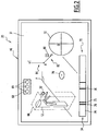
- FIG. 1 illustrates a video surveillance system 10 according to the invention, hereinafter system 10.
- the system 10 is intended for monitoring a given installation, for example a building, a factory, a warehouse, a public transport installation such as for example an airport or a station, etc.
- the system 10 comprises a first and a second equipment 12, 13, a first, a second and a third camera 14, 16, 18 respectively, a first and a second monitoring station 20, 22, hereinafter positions 20, 22, and a management server 24, hereinafter server 24.
- the equipment 12, 13 are remotely controllable.
- the equipment 12, 13 are connected to the server 24.
- the equipment 12, 13 are equipment of the installation that the system 10 makes it possible to monitor.
- the equipment 12, 13 are turnstiles.
- the equipment 12, 13 are one of the following: an access door, a programmable display panel, a machine tool, or any other device of the considered installation whose remote control is feasible and being in the field of view of at least one of the cameras 14, 16, 18.
- the system 10 comprises one or more remote-controllable equipment 12, 13 connected to the server 24.
- the cameras 14, 16, 18 are connected to at least one monitoring station 20, 22.
- the first camera 14 is connected to the first station 20, and the second and third cameras 16, 18 are connected to the second station 22.
- Each camera 14, 16, 18 has a field of view 26, 28, 30 and is adapted to deliver to the station 20, corresponding 22 of the images 31 (FIG. Figure 2 ) each corresponding to a shooting of its field of view 26, 28, 30.
- the cameras 14, 16, 18 are steerable, that is, they are adapted to scroll their field of view 26, 28, 30 respectively.
- the set of possible fields of view 26, 28, 30 of a camera 14, 16, 18 forms an observation field 32, 34, 36 of the camera.
- the field of view 32, 34, 36 corresponds in practice to all the elements of the installation that the camera 14, 16, 18 corresponding is suitable to observe.
- the observation fields 32, 34 of the first and second cameras 14, 16 have a first common portion 38, and the observation fields 34, 36 of the second and third cameras 16, 18 have a second common portion 40 .
- the first equipment 12 is located in the observation field 32 of the first camera 14 and the second equipment 13 is located in the first common part 38.
- cameras 14, 16, 18 are PTZ type dome cameras, English acronym for "Pan Tilt Zoom", which means “Pan Tilt Magnification”.
- the field of view 26, 28, 30 of the cameras 14, 16, 18 is thus pivotable about two orthogonal, hereinafter panoramic axis 42 and inclination axis 44 (in dashed lines on the Figure 1 and shown only for the first camera 14) and is movable in depth, i.e., the cameras are capable of achieving magnifications and narrowing. This allows the cameras to have a field of observation 32, 34, 36 of maximum size and to be able to change the magnification level of the elements of the installation.
- Each camera 14, 16, 18 is configured to provide each station 20, 22 to which it is connected information representative of its current orientation.
- the cameras 14, 16, 18 thus provide information representative of their current orientation along their panoramic axis 42 and their inclination axis 44, as well as their current magnification level.
- the monitoring stations 20, 22 are connected to the server 24 and to at least one of the cameras 14, 16, 18.
- Each station 20, 22 comprises display means 46, input means 48 and a processing unit 50.
- the display means 46 comprise a screen adapted to display the images 31 provided by the cameras 14, 16, 18 connected to the corresponding station 20, 22.
- the input means 48 are suitable for allowing an operator to enter data to interact with the display means 46 and the processing unit 50, and in particular with a graphical interface generated by the processing unit 50 on the means. 46.
- the input means 48 comprise a keyboard (not shown) and a mouse associated with a cursor 52 viewable on the display means 46 and that the operator of the station 20, 22 corresponding moves on the means of display. display 46 by moving the mouse. The operator interacts for example with an element displayed on the display means 46 by positioning the cursor 52 above the element and then actuating the mouse.
- the display means 46 and the gripping means 48 are adapted to allow the operator to interact with the display means 46 tactilely.
- the processing unit 50 is able to drive the display means 46 and the input means 48 and to communicate with the server 24.
- the processing unit 50 is suitable for displaying on the means for displaying images 31 provided by the associated cameras 14, 16, 18 and generating a graphic interface 54 superimposed on the images 31.
- the processing unit 50 is connected to the cameras 14, 16, 18 associated and comprises a processor and a memory (not shown) comprising software necessary for the conventional operation of the processing unit 50.
- the processing unit 50 includes a graphical interface generation module 56 configured to generate the graphical interface 54, which is described in more detail below.
- the GUI module 56 includes an augmented reality module 58 and a control module 60.
- the augmented reality module 58 comprises a calculation module 62 configured to transpose the position of the points of the observation field 32, 34, 36 of the cameras 14, 16, 18 associated with the station 20, 22 corresponding to a position on the means of 46, and vice versa.
- the calculation module 62 is configured to determine the position of the points of the observation field 32, 34, 36 from their position on the images 31 displayed on the display means 46 and parameters provided by the camera. corresponding and indicating the orientation of the camera, and to determine the position of the points on the display means 46 from the corresponding position in the field of view 32, 34, 36 and the parameters provided by the camera.
- the calculation module 62 thus makes it possible to establish a correspondence between the position of the points of the observation fields 32, 34, 36 and the position of the points of the images 31 displayed on the display means 46. As will be seen from FIG. subsequently, this makes it possible to remanently associate the position of an element of the graphic interface 54 with the position of a point in the field of view of one or more cameras 14, 16, 18.
- the augmented reality module 58 comprises a rendering module 64 configured to generate, on the display means 46, the graphic interface 54 superimposed on the images 31 from data provided by the calculation module 62, by the cameras 14, 16, 18 and the server 24.
- the augmented reality module 58 controls the display of the graphical interface 54 from the data it receives from the other organs of the system 10 which he is connected to.
- the control module 60 is configured to support the interactions of the input means 48 with the graphical interface 54.
- control module 60 is configured to detect the data input by the operator via an interaction of the input means 48 with the graphic interface 54, in particular via the cursor 52 displayed on the display means 46, and transmit the corresponding information to the organ of the system 10 concerned, such as the camera 14, 16, 18, the equipment 12, 13 that the operator wishes to control or the augmented reality module 58.
- the data are intended for a camera or equipment 12, 13, the information is conveyed either directly to the corresponding camera 14, 16, 18, or to the equipment 12, 13 via the server 24.
- the server 24 is able to allow the communication of the monitoring stations 20, 22 with each other and with the equipment 12, 13, as well as to supply configuration data of the system 10 to the stations 20, 22.
- the configuration data include data relating to the equipment 12, 13, or to virtual objects whose display is made on the display means 46 of the stations 20, 22. This is described in more detail in the following. .
- the graphical interface 54 will now be described in more detail with reference to the Figures 1 is 2.
- the graphic interface 54 of the stations 20, 22 includes interface elements superimposed on the images 31 and through which the operator interacts with the equipment 12, 13 or the cameras 14, 16, 18 associated with the monitoring station 20 , 22 from which he operates.
- the graphical interface 54 is configured to display an identification element 66 associated with the equipment 12, 13.
- the identification element 66 is directly displayed on the associated equipment 12, 13 so that the identification element 66 is superimposed on the equipment 12, 13 in the images 31.
- the identification element 66 is a schematic representation of the equipment 12, 13.
- the identification element 66 is associated with a point of the equipment 12, 13 so that it moves with the equipment 12, 13 when the field of view 26, 28, 30 of the camera 14, 16 , 18 corresponding is changed due to a movement of the camera according to one or more of its degrees of freedom.
- the identification element of the equipment 12 is a partially opaque parallelepiped in which the equipment 12 is inscribed.
- the identification element 66 is selectable via the input means 48, for example via the cursor 52.
- the graphical interface 54 is configured to display an equipment control interface 68, hereinafter control interface 68, for the control of the equipment 12.
- control interface 68 is selectively activatable by the selection of the corresponding identification element 66 via the input means 48.
- the control interface 68 comprises control buttons 69 respectively associated with a preconfigured action of the equipment 12, 13 associated, such as for example the opening of the equipment 12, 13 if it is a door, its rotation if This is a turnstile, turning it on, turning it off, displaying a preprogrammed message if it is a programmable display panel, etc.
- control interface 68 also comprises means for setting the identification element 66, for example to parameterize the color of the identification element, its opacity, etc.
- the graphical interface 54 comprises a dedicated control interface 68 for each device 12.
- the graphic interface 54 comprises a control interface 68 dedicated to several pieces of equipment 12, 13 and via which the operator can control the corresponding equipment items 12, 13.
- the display of the control interface 68 is for example made for a predefined duration after the selection of the identification element 66, or until a new operation of the input means 48 by the operator.
- the graphic interface 54 is configured to display a camera control interface 70, hereinafter camera interface 70, for controlling the orientation of the camera 14, 16, 18 whose images 31 are displayed on the display means 46.
- the camera interface 70 comprises a virtual joystick 72 operable via the cursor 52 for the reorientation of the camera 14, 16, 18 in two or more degrees of freedom of the camera simultaneously.
- the camera interface 70 comprises an orientation bar 74 representing all of the possible orientations of the camera 14, 16, 18 according to one of its degrees of freedom, for example around its panoramic axis 42, as well as the current orientation of the camera, represented by an orientation key 75 hatched on the Figure 2 .
- Each location of the orientation bar 74 corresponds to a given orientation of the camera 14, 16, 18 according to the degree of freedom associated.
- Each location of the orientation bar 74 is selectable via the input means 48, either directly or by moving the orientation key 75. Selecting a location of the orientation bar triggers the camera recall 14, 16, 18 corresponding in the associated orientation.
- orientation bar 74 only a portion of the locations of the orientation bar 74 is selectable to trigger the recall of the corresponding camera 14, 16, 18 in the associated orientation.
- the camera interface 70 includes selectively activatable return buttons 76 for controlling the recall of the camera 14, 16, 18 in a preconfigured orientation.
- the return keys 76 are for example associated with orientations of the camera 14, 16, 18 which correspond to fields of view 26, 28, 30 in which equipment 12, 13 is located. In the embodiment of the Figure 1 , the return keys 76 are located on the orientation bar 74. Alternatively, the return keys 76 are located on the virtual joystick 72, or are arranged in a dedicated location of the graphical interface 54.
- the graphic interface 54 is also configured to display virtual objects 70 respectively associated with a particular point of the field of view 32, 34, 36 of the camera 14, 16, 18 whose images 31 are displayed on the screens. display means 46.
- the virtual objects 78 are included in the group consisting of: a translucent geometric shape, an opaque geometric shape, a set of alphanumeric characters, an icon or a symbol, for example signaling.
- the Figure 2 illustrates a virtual object 78 associated with a point of the field of view 32 of the first camera 14 and represented by a cross.
- the virtual object 78 is a translucent octagon.
- the virtual objects 78 are generated by the graphical interface generation module 56 of the monitoring stations 20, 22 from the configuration data provided by the server 24. This is described in more detail in the following.
- the cameras 14, 16, 18 provide each station 20, 22 to which they are connected the shots they take from their field of view 26, 28, 30.
- the processing unit 50 stations 20, 22 carries out the display of a temporal sequence of the corresponding images 31 on the corresponding display means 46.
- the operator of the first station 20 sees a temporal sequence of images 31 delivered by the first camera 14 and on which the equipment 12 appears.
- the operator of the second station 22 can switch selectively between the images 31 provided by one and the other of the second and third cameras 16, 18, for example by means of a key (not shown) on the input means 48 or via an element (not shown) of the graphical interface 54 provided for this purpose.
- the operator displays a sequence of images 31 on which the second equipment 13 appears.
- the graphic interface generation modules 54 of the stations 20, 22 generate and display the corresponding graphic interface 54 on the associated display means 46 and superimposed on the images 31.
- the processing unit 50 receives the configuration data from the server 24, for example at a regular frequency.
- the data contains the information relating to the identification elements 66 of the equipment 12, 13 and virtual objects 78 located in the field of view 32, 34, 36 of at least one of the cameras 14, 16, 18 to which the station 20, 22 corresponding is connected.
- the augmented reality module 58 processes the data, generates the identification elements 66 and the virtual objects 78, and controls the display on the graphical interface 54. If the field of view whose images 31 are displayed does not contain point with which is associated an identification element 66 or a virtual object 78, no identification element 66 or virtual object 78 is therefore viewable on the corresponding display means 46.
- the augmented reality module 58 updates the display of the identification elements 66 and the virtual objects 78 when the orientation of the camera 14, 16, 18 whose images 31 are displayed is modified so that the elements identification 66 and virtual objects 78 behave as if they were physically present in the corresponding field of view 32, 34, 36.
- the calculation module 62 determines the position on the images 31 of the points of the observation field or fields 32, 34, 36 corresponding to which are associated an identification element 66 or a virtual object 78, and the module of rendering 64 controls the display of the graphical interface 54 accordingly.
- the operator selects the corresponding identification element 66 via the cursor 52.
- the interaction of the input means 48 with the graphic interface 54 is detected by the control module 60 This triggers the display of the control interface 68 associated with the equipment 12, 13 and via which the operator selects the command which he wishes the equipment to carry out via the control buttons 69. selected command, the corresponding information is detected by the control module 60 and relayed to the server 24, which transmits it to the equipment 12, 13 recipient.
- the equipment 12, 13 then executes the command.
- the operator uses the camera interface 70. For example, he modifies the orientation of the camera 14 according to two degrees simultaneously by using the virtual joystick 72, or selects a preconfigured orientation of the camera via a recall key 76. The operator can also scroll the orientation key 75 along the orientation bar 74, or modify the position of the orientation key 75 by positioning the cursor 52 on the orientation bar 74 and by actuating the input means 46. These interactions are detected by the corresponding control module 60, which relay the corresponding command directly to the camera 14, 16, 18 recipient. The camera then changes its orientation accordingly.
- the operator can create a virtual object 78 and associate the virtual object 78 with a particular point in the field of view 26, 28, 30 of one of the cameras 14, 16, 18 to which the item 20 is connected.
- the operator selects a particular point of the image 31, for example by pointing the cursor 52 on the point in question and by actuating a particular key of the input means 48, such as a button particular of the mouse.
- the point thus defined corresponds to the point at which the virtual object 78 will be associated.
- the operator then defines the type and the shape of the virtual object 78, for example by selecting the virtual object 78 from a list of virtual object models 78, by drawing a closed form via the cursor 52 or by entering the Corresponding alphanumeric characters via the input means 58.
- the virtual object 78 Once the virtual object 78 has been selected, drawn or inputted, its superimposition on the images 31 is carried out by the augmented reality module 58 of the corresponding station 20, 22, the associated data. to the virtual object 78 are sent to the server 24 and the first operating mode is disabled.
- the server 24 stores the data of the virtual objects 78 generated via the stations 20, 22 and communicates them to the stations 20, 22 which are connected to at least one camera whose observation field 32, 34, 36 comprises the point at which the virtual object 78 is associated.
- a virtual object 78 associated with a point of the first common portion 38 will be viewable on the display means 46 of the first station 20 as the second station 22 when the point associated with the virtual object 78 will be in the field of view 26, 28 of the corresponding camera 14, 16, even if the second station 20 does not have the first mode of operation, for example because it is disabled.
- the virtual objects 78 are adapted to be deleted from the stations 20, 22, for example by means of a key of the input means provided for this purpose, or by interaction with the virtual object 78 in question.
- the operator extracts from the images 31 geometrical information 80 relating to points of the fields of view 26, 28, 30 of the camera 14, 16, 18 whose images 31 are displayed on the means of view. display 46.
- the geometric information 80 is determined by assuming that the positions in the field of view 32, 34, 36 corresponding and designated by the cursor 52 all belong to a predetermined horizontal plane P or all belong to a orthogonal to the horizontal plane P.
- the horizontal plane P is the ground plane of the installation.
- the operator actuates a particular button of the input means 48, or a key provided for this purpose on the graphical interface 54.
- the operator extracts geometric information 80 from the images 31 by positioning the cursor 52 on a point of the display means 46 (point A on the Figure 2 ) corresponding to a position in the corresponding field of view 32, 34, 36 and about which it wishes to obtain geometric information 80, and actuates the input means 48.
- This freezes the position of the point A and triggers the display a segment between the point A and the point of the display means 46 to which the cursor 52 points (point B in horizontal mode 82 and point C in vertical mode 84), as well as the display of one or more information geometric 80.
- the geometric information 80 includes an indication of the distance in the field of view 32, 34, 36 between the point of the field of view corresponding to point A and the position in the corresponding field of view of point B or C.
- the distance between the points A and B or C is determined by the calculation module 62 of the station 20, 22, which transposes the position on the display means 46 of the points A and B or C in positions in the field of view 32, 34, 36 and calculates the distance between these positions.
- the vertical mode 84 thus makes it possible to determine the height relative to the horizontal plane P of the objects that can be viewed on the images 31, and the horizontal mode 82 makes it possible to measure the distance in the plane P between two objects.
- the geometrical information 80 also includes or alternatively an indication of the speed of displacement of the point of field of view 26, 28, 30 corresponding to the point B or C.
- the operator designates with the point A to the object of which it wishes to measure the speed of displacement then points again the cursor 52 on the object but on a subsequent image 31, and actuates a second time the input means 48.
- the calculation module 62 then calculates the speed of the object from the positions of the point A and the point B or C thus fixed and the respective dates of the images 31 displayed at the respective instants where the operator has fixed the point A, respectively the point B or C.
- one or more of the stations 20, 22 implement an automatic motion detection algorithm such that geometric information 80 comprising a speed indication in the horizontal plane P is displayed on the associated graphic interface 54 for all or part of the objects. moving in the field of view 26, 28, 30 corresponding, or for all or part of the objects having certain predetermined characteristics, for example size or color.
- the operator switches between the vertical mode 84 and the horizontal mode 82 via a key provided for this purpose on the input means 48 or on the graphical interface 54, or by keeping a touch of the means of seizure 48 depressed.
- the display of identification elements 66 associated with the equipment 12, 13 on the graphic interface 54 of the stations facilitates the identification of the equipment 12, 13.
- the display of the identification elements 66 superimposed on the equipment 12, 13 facilitates the location of the equipment 12, 13 on the images 31, which further improves the ergonomics of the stations 20, 22.
- the graphic interface 54 of the stations makes it possible to remotely control the equipment 12, 13 directly via the display means 46 and by means of the same graphic interface 54 via which it displays the images 31, which improves the ergonomics of the stations 20, 22 compared to a scenario in which the equipment 12, 13 are remotely controlled by a dedicated interface.
- the control of the equipment 12, 13 via the control interfaces 68 activated by the selection of associated identification elements 66 reduces the risks of carrying out the control of the bad equipment and improves the response time of the operator because he does not need to divert his attention from the pictures.
- the first mode of operation allows the various operators of the system 10 to share graphic information and in the context of images 31 provided by the cameras.
- it makes it possible to centrally configure the areas of privacy masking of the installation that the system 10 makes it possible to monitor, which, in known video surveillance systems, must be made specifically for each camera.
- the masking areas may for example be configured as opaque virtual objects 78 whose shape is suitably chosen.
- the second mode of operation allows operators to obtain geometric information on the elements of the monitored installation directly via the monitoring stations, and this in a simple manner and without prior knowledge of the installation.
- the server 24 makes it possible to centralize the configuration of the stations 20, 22 in general, which facilitates the operation of adding or deleting a station to the system 10 and makes the latter more flexible.
- the stations 20, 22 are adapted to simultaneously display the images 31 provided by several or all the cameras to which they are connected, for example by dedicating to each camera 14, 16, 18 a portion of the display means 46.
- the graphic interface generating module 56 of the stations 20, 22 generates as many graphic interfaces 54 as there are cameras whose images 31 are displayed on the display means 46, the operation each graphical interface 54 being the same as that described above.
Description
La présente invention concerné un système de vidéosurveillance, comprenant :
- au moins une caméra comportant un champ d'observation et propre à délivrer des images de son champ d'observation,
- au moins un équipement commandable à distance et situé dans le champ d'observation de ladite caméra,
- au moins un poste de surveillance connecté à au moins une caméra et comprenant des moyens de saisie, des moyens d'affichage pour l'affichage d'une séquence temporelle d'images délivrées par la ou chaque caméra correspondante, et un module de génération d'interface configuré pour générer une interface graphique en surimpression sur les images affichées sur les moyens d'affichage.
- at least one camera having an observation field and capable of delivering images of its field of observation,
- at least one remote controllable equipment located in the field of view of said camera,
- at least one monitoring station connected to at least one camera and comprising input means, display means for displaying a temporal sequence of images delivered by the or each corresponding camera, and a generation module; interface configured to generate a graphical interface superimposed on the images displayed on the display means.
L'invention se situe dans le domaine des systèmes de vidéosurveillance.The invention lies in the field of video surveillance systems.
Ces systèmes sont couramment utilisés pour surveiller des installations de divers types, telles que par exemple des installations de transport public, des bâtiments, des usines, des espaces commerciaux ou des hangars, et en particulier pour surveiller certains des équipements que comprennent ces installations.These systems are commonly used to monitor facilities of various types, such as, for example, public transport facilities, buildings, factories, commercial spaces or hangars, and in particular to monitor some of the equipment that these facilities comprise.
Les caméras de ces systèmes fournissent des images de leur champ d'observation au poste de surveillance au moyen duquel un opérateur réalise à proprement parler la surveillance de l'installation.The cameras of these systems provide images of their field of view at the monitoring station by means of which an operator realizes the actual monitoring of the installation.
Afin d'améliorer l'ergonomie des postes de surveillance, il est connu de munir ces derniers d'un module de génération d'interface graphique configuré pour générer l'interface graphique en surimpression sur les images délivrées par la caméra. L'opérateur peut alors accéder aux fonctionnalités de l'interface graphique directement depuis les images fournies par les caméras. Toutefois, les systèmes de surveillance connus présentent des inconvénients.In order to improve the ergonomics of the monitoring stations, it is known to provide the latter with a graphical interface generation module configured to generate the graphic interface superimposed on the images delivered by the camera. The operator can then access the features of the GUI directly from the images provided by the cameras. However, known surveillance systems have drawbacks.
En effet, la commande des équipements de l'installation y est généralement réalisée via une interface dédiée. Pour commander le ou les équipements, l'opérateur doit alors diviser son attention entre les images et l'interface dédiée à la commande des équipements, ce qui diminue l'efficacité de la surveillance et augmente le temps de réaction de l'opérateur aux évènements se produisant dans la zone surveillée. L'ergonomie du poste de surveillance n'est alors pas optimale.Indeed, the control of the equipment of the installation is generally carried out via a dedicated interface. To control the equipment or equipment, the operator must then divide his attention between the images and the interface dedicated to the control of the equipment, which decreases the effectiveness of the monitoring and increases the reaction time of the operator to the events occurring in the supervised area. The ergonomics of the monitoring station is not optimal.
L'un des objets de l'invention est donc de proposer un système de vidéosurveillance dont l'ergonomie est améliorée.One of the objects of the invention is therefore to propose a video surveillance system whose ergonomics are improved.
A cet effet, l'invention porte sur un système de vidéosurveillance tel que défini ci-dessus, caractérisé en ce que le module de génération d'interface du ou de chaque poste de surveillance est configuré pour générer et afficher, via l'interface graphique, un élément d'identification dudit équipement en surimpression directement sur l'équipement, de telle que sorte que l'élément d'identification est superposé à l'équipement sur les images, en ce que l'élément d'identification est sélectivement activable via les moyens de saisie pour déclencher l'affichage sur l'interface graphique d'une interface de commande pour la commande à distance d'au moins un équipement, et en ce que le système de vidéosurveillance comprend des moyens de commande pour la commande du ou de chaque équipement en fonction d'informations saisies par un utilisateur via l'interface de commande.For this purpose, the invention relates to a video surveillance system as defined above, characterized in that the interface generation module of the or each monitoring station is configured to generate and display, via the graphical interface. , a identification element of said equipment superimposed directly on the equipment, so that the identification element is superimposed on the equipment on the images, in that the identification element is selectively activatable via the means method for triggering the display on the graphical interface of a control interface for the remote control of at least one device, and in that the video surveillance system comprises control means for controlling the or each equipment based on information entered by a user via the control interface.
Selon d'autres aspects de l'invention, le système de vidéosurveillance comprend en outre une ou plusieurs des caractéristiques techniques suivantes, prise(s) isolément ou selon toute(s) combinaison(s) techniquement possible(s) :
- au moins un poste de surveillance comprend un deuxième mode de fonctionnement dans lequel l'interface graphique dudit poste de surveillance est adaptée pour réaliser l'affichage d'informations géométriques comprenant la distance, dans le champ d'observation de la caméra dont les images sont affichées sur les moyens d'affichage, entre deux points des moyens d'affichage, et/ou la vitesse de déplacement d'un objet dans le champ d'observation de la caméra dont les images sont affichées sur les moyens d'affichage ;
- le deuxième mode de fonctionnement comprend un mode de fonctionnement horizontal dans lequel les informations géométriques sont projetées dans un plan horizontal prédéterminé du champ d'observation de la caméra dont les images sont affichées sur les moyens d'affichage, et un mode de fonctionnement vertical dans lequel les informations géométriques sont projetées sur une droite orthogonale au plan horizontal ;
- le poste de surveillance comprend un premier mode de fonctionnement dans lequel l'interface graphique associée est adaptée pour la création d'objets virtuels et l'association de chaque objet virtuel à une position du champ d'observation d'une caméra à laquelle ledit poste de surveillance est connecté, de sorte qu'un objet virtuel est affiché sur les images fournies par ladite caméra et dans lesquelles la position du champ d'observation associée à l'objet virtuel est affichée ;
- chaque objet virtuel est affiché sur les images fournies par chacune des caméras connectées audit poste de surveillance et dont le champ d'observation comprend la position à laquelle l'objet virtuel est associé ;
- chaque objet virtuel est affiché sur les images fournies par chacune des caméras du système de vidéosurveillance et dont le champ d'observation comprend la position à laquelle l'objet virtuel est associé ;
- un objet virtuel est compris dans le groupe consistant en: une forme géométrique translucide, une forme géométrique opaque, un ensemble de caractères alphanumériques, une icône ou un symbole ;
- au moins une caméra est orientable, l'interface graphique d'au moins l'un des postes de surveillance connectés à ladite caméra comprenant au moins une touche de rappel sélectivement actionnable pour déclencher le rappel de la caméra dans une orientation prédéterminée ;
- au moins une caméra est orientable, l'interface graphique d'au moins l'un des postes de surveillance connectés à ladite caméra comprenant une barre d'orientation représentant l'ensemble des orientations possibles de ladite caméra selon le ou l'un des degrés de liberté de ladite caméra ; et
- la barre d'orientation comprend un ou plusieurs emplacements sélectionnables, la sélection d'un emplacement sélectionnable de la barre d'orientation étant configurée pour déclencher le rappel de ladite caméra dans l'orientation correspondante.
- at least one monitoring station comprises a second mode of operation in which the graphic interface of said monitoring station is adapted to perform the display of geometric information including the distance, in the field of view of the camera whose images are displayed on the display means, between two points of the display means, and / or the speed of movement of an object in the field of view of the camera whose images are displayed on the display means;
- the second mode of operation comprises a horizontal mode of operation in which the geometric information is projected in a predetermined horizontal plane of the field of view of the camera whose images are displayed on the display means, and a vertical mode of operation in which geometrical information is projected on a line orthogonal to the horizontal plane;
- the monitoring station comprises a first mode of operation in which the associated graphical interface is adapted for the creation of virtual objects and the association of each virtual object to a position of the field of view of a camera to which said station monitor is connected, so that a virtual object is displayed on the images provided by said camera and in which the position of the observation field associated with the virtual object is displayed;
- each virtual object is displayed on the images provided by each of the cameras connected to said monitoring station and whose field of view includes the position with which the virtual object is associated;
- each virtual object is displayed on the images provided by each of the cameras of the video surveillance system and whose field of view includes the position with which the virtual object is associated;
- a virtual object is included in the group consisting of: a translucent geometric shape, an opaque geometric shape, a set of alphanumeric characters, an icon or a symbol;
- at least one camera is steerable, the graphic interface of at least one of the monitoring stations connected to said camera comprising at least one selectively operable return button for triggering the recall of the camera in a predetermined orientation;
- at least one camera is steerable, the graphical interface of at least one of the monitoring stations connected to said camera comprising an orientation bar representing all of the possible orientations of said camera according to the one or one of the degrees freedom of said camera; and
- the orientation bar comprises one or more selectable locations, the selection of a selectable location of the orientation bar being configured to trigger the recall of said camera in the corresponding orientation.
L'invention sera mieux comprise à la lecture de la description détaillée qui va suivre, donnée uniquement à titre d'exemple et faite en se référant aux Figures annexées, sur lesquelles :
- la
Figure 1 est une représentation schématique du système de vidéosurveillance selon l'invention ; et - la
Figure 2 est une représentation schématique de l'interface graphique d'un poste de surveillance du système de vidéosurveillance de laFigure 1 .
- the
Figure 1 is a schematic representation of the video surveillance system according to the invention; and - the
Figure 2 is a schematic representation of the graphical interface of a surveillance station of the video surveillance system of theFigure 1 .
La
Le système 10 est destiné à la surveillance d'une installation donnée, par exemple un bâtiment, une usine, un entrepôt, une installation de transport public telle que par exemple un aéroport ou une gare, etc. Le système 10 comprend un premier et un deuxième équipements 12, 13, une première, une deuxième et une troisième caméras 14, 16, 18 respectivement, un premier et un deuxième postes de surveillance 20, 22, ci-après postes 20, 22, et un serveur de gestion 24, ci-après serveur 24.The
Les équipements 12, 13 sont commandables à distance. Les équipements 12, 13 sont connectés au serveur 24. Les équipements 12, 13 sont des équipements de l'installation que le système 10 permet de surveiller. Dans l'exemple de la
En variante, les équipements 12, 13 sont l'un des éléments suivants : une porte d'accès, un panneau d'affichage programmable, une machine outil, ou encore tout dispositif de l'installation considérée dont la commande à distance est réalisable et se trouvant dans le champ d'observation d'au moins l'une des caméras 14, 16, 18.Alternatively, the
En variante, le système 10 comprend un ou plus de deux équipements 12, 13 commandables à distances et connectés au serveur 24.As a variant, the
Les caméras 14, 16, 18 sont connectées à au moins un poste de surveillance 20, 22. Dans l'exemple de la
Chaque caméra 14, 16, 18 possède un champ de vue 26, 28, 30 et est propre à délivrer au poste 20, 22 correspondant des images 31 (
Les caméras 14, 16, 18 sont orientables, c'est-à-dire qu'elles sont propres à faire défiler leur champ de vue 26, 28, 30 respectif.The
L'ensemble des champs de vue 26, 28, 30 possibles d'une caméra 14, 16, 18 forme un champ d'observation 32, 34, 36 de la caméra. Le champ d'observation 32, 34, 36 correspond en pratique à l'ensemble des éléments de l'installation que la caméra 14, 16, 18 correspondante est propre à observer.The set of possible fields of
Les champs d'observation 32, 34 de la première et deuxième caméras 14, 16 présentent une première partie commune 38, et les champs d'observation 34, 36 de la deuxième et de la troisième caméras 16, 18 présentent une deuxième partie commune 40.The
Dans l'exemple de la
Dans l'exemple de la
Chaque caméra 14, 16, 18 est configurée pour fournir à chaque poste 20, 22 auquel elle est connecté des informations représentatives de son orientation actuelle. Dans le cas de caméras dôme de type PTZ, les caméras 14, 16, 18 fournissent ainsi des informations représentatives de leur orientation actuelle selon leur axe panoramique 42 et leur axe d'inclinaison 44, ainsi que leur niveau de grossissement actuel.Each
Les postes de surveillance 20, 22 sont connectés au serveur 24 et à au moins l'une des caméras 14, 16, 18. Chaque poste 20, 22 comprend des moyens d'affichage 46, des moyens de saisie 48 et une unité de traitement 50.The
Les moyens d'affichage 46 comprennent un écran propre à réaliser l'affichage des images 31 fournies par les caméras 14, 16, 18 connectées au poste 20, 22 correspondant.The display means 46 comprise a screen adapted to display the
Les moyens de saisie 48 sont propres à permettre à un opérateur de saisir des données pour interagir avec les moyens d'affichage 46 et l'unité de traitement 50, et notamment avec une interface graphique générée par l'unité de traitement 50 sur les moyens d'affichage 46. Les moyens de saisie 48 comprennent un clavier (non représenté) et une souris associée à un curseur 52 visualisable sur les moyens d'affichage 46 et que l'opérateur du poste 20, 22 correspondant déplace sur les moyens d'affichage 46 en déplaçant la souris. L'opérateur interagit par exemple avec un élément affiché sur les moyens d'affichage 46 par positionnement du curseur 52 au-dessus de l'élément puis actionnement de la souris.The input means 48 are suitable for allowing an operator to enter data to interact with the display means 46 and the
En variante, les moyens d'affichage 46 et les moyens de saisie 48 sont adaptés pour permettre à l'opérateur d'interagir tactilement avec les moyens d'affichage 46.In a variant, the display means 46 and the gripping
En référence aux
L'unité de traitement 50 est connectée aux caméras 14, 16, 18 associées et comprend un processeur et une mémoire (non représentés) comprenant des logiciels nécessaires au fonctionnement classique de l'unité de traitement 50. En outre, l'unité de traitement 50 comprend un module de génération d'interface graphique 56 configuré pour générer l'interface graphique 54, qui est décrite plus en détail ci-dessous.The
Le module d'interface graphique 56 comprend un module de réalité augmentée 58 et un module de contrôle 60.The
Le module de réalité augmentée 58 comprend un module de calcul 62 configuré pour transposer la position des points du champ d'observation 32, 34, 36 des caméras 14, 16, 18 associées au poste 20, 22 correspondant en une position sur les moyens d'affichage 46, et inversement.The
Plus spécifiquement, le module de calcul 62 est configuré pour déterminer la position des points du champ d'observation 32, 34, 36 à partir de leur position sur les images 31 affichées sur les moyens d'affichage 46 et de paramètres fournis par la caméra correspondante et indiquant l'orientation de la caméra, et pour déterminer la position des points sur les moyens d'affichage 46 à partir de la position correspondante dans le champ d'observation 32, 34, 36 et des paramètres fournis par la caméra. Le module de calcul 62 permet ainsi d'établir une correspondance entre la position des points des champs d'observation 32, 34, 36 et la position des points des images 31 affichées sur les moyens d'affichage 46. Comme on le verra par la suite, ceci permet d'associer de façon rémanente la position d'un élément de l'interface graphique 54 à la position d'un point du champ d'observation d'une ou plusieurs caméras 14, 16, 18.More specifically, the
En outre, le module de réalité augmentée 58 comprend un module de rendu 64 configuré pour générer, sur les moyens d'affichage 46, l'interface graphique 54 en surimpression sur les images 31 à partir de données fournies par le module de calcul 62, par les caméras 14, 16, 18 et par le serveur 24. En d'autres termes, le module de réalité augmentée 58 pilote l'affichage de l'interface graphique 54 à partir des données qu'il reçoit des autres organes du système 10 auxquels il est connecté.In addition, the
Le module de contrôle 60 est configuré pour prendre en charge les interactions des moyens de saisie 48 avec l'interface graphique 54.The
Plus spécifiquement, le module de contrôle 60 est configuré pour détecter la saisie de données par l'opérateur via une interaction des moyens de saisie 48 avec l'interface graphique 54, notamment via le curseur 52 affiché sur les moyens d'affichage 46, et transmettre l'information correspondante à l'organe du système 10 concerné, tel que la caméra 14, 16, 18, les équipements 12, 13 que l'opérateur souhaite commander ou le module de réalité augmentée 58. Dans le cas où les données sont destinées à une caméra ou à un équipement 12, 13, l'information est acheminée soit directement à la caméra 14, 16,18 correspondante, soit à l'équipement 12, 13 via le serveur 24.More specifically, the
Le serveur 24 est propre à permettre la communication des postes de surveillance 20, 22 entre eux et avec les équipements 12, 13, ainsi qu'à fournir des données de configuration du système 10 aux postes 20, 22.The
Les données de configuration comprennent notamment des données relatives aux équipements 12, 13, ou encore à des objets virtuels dont l'affichage est réalisé sur les moyens d'affichage 46 des postes 20, 22. Ceci est décrit plus en détail dans ce qui suit.The configuration data include data relating to the
L'interface graphique 54 va maintenant être décrite plus en détail en référence aux
L'interface graphique 54 est configurée pour permettre à l'opérateur d'interagir avec les caméras 14, 16, 18 associées au poste 20, 22 correspondant et avec les équipements 12, 13. En outre l'interface graphique est configurée pour activer sélectivement :
- un premier mode de fonctionnement dans lequel l'opérateur créé des objets virtuels et les associe à un point
d'un champ d'observation - un deuxième mode de fonctionnement dans lequel l'opérateur extrait des informations géométriques du champ de vue de la caméra 14, 16, 18 dont les
images 31 sont affichées.
- a first mode of operation in which the operator creates virtual objects and associates them with a point of an
observation field - a second mode of operation in which the operator extracts geometric information from the field of view of the
camera images 31 are displayed.
L'interface graphique 54 des postes 20, 22 comprend des éléments d'interface affichés en surimpression sur les images 31 et via lesquels l'opérateur interagit avec les équipements 12, 13 ou les caméras 14, 16, 18 associées au poste de surveillance 20, 22 depuis lequel il opère.The
Plus spécifiquement, en référence à la
Préférentiellement, l'élément d'identification 66 est une représentation schématique de l'équipement 12,13.Preferably, the
L'élément d'identification 66 est associé à un point de l'équipement 12, 13 de telle sorte qu'il se déplace avec l'équipement 12, 13 lorsque le champ de vue 26, 28, 30 de la caméra 14, 16, 18 correspondante est modifié du fait d'un mouvement de la caméra selon un ou plusieurs de ses degrés de liberté.The
Dans l'exemple de la
L'élément d'identification 66 est sélectionnable via les moyens de saisie 48, par exemple via le curseur 52.The
L'interface graphique 54 est configurée pour réaliser l'affichage d'une interface de commande d'équipement 68, ci-après interface de commande 68, pour la commande des équipements 12. L'affichage de l'interface de commande 68 est sélectivement activable par la sélection de l'élément d'identification 66 correspondant via les moyens de saisie 48.The
L'interface de commande 68 comprend des boutons de commande 69 respectivement associés à une action préconfigurée de l'équipement 12, 13 associé, telle que par exemple l'ouverture de l'équipement 12, 13 s'il s'agit d'une porte, sa rotation s'il s'agit d'un tourniquet, sa mise en marche, son extinction, l'affichage d'un message préprogrammé s'il s'agit d'un panneau d'affichage programmable, etc.The
Dans des modes de réalisation particuliers, l'interface de commande 68 comprend également des moyens de paramétrage de l'élément d'identification 66, par exemple pour paramétrer la couleur de l'élément d'identification, son opacité, etc.In particular embodiments, the
L'interface graphique 54 comprend une interface de commande 68 dédiée pour chaque équipement 12.The
En variante, l'interface graphique 54 comprend une interface de commande 68 dédiée à plusieurs équipements 12, 13 et via laquelle l'opérateur peut commander les équipements 12, 13 correspondants.In a variant, the
L'affichage de l'interface de commande 68 est par exemple réalisée pour une durée prédéfinie après la sélection de l'élément d'identification 66, ou encore jusqu'à un nouvel actionnement des moyens de saisie 48 par l'opérateur.The display of the
En outre, l'interface graphique 54 est configurée pour réaliser l'affichage d'une interface de commande de caméra 70, ci-après interface de caméra 70, pour la commande de l'orientation de la caméra 14, 16, 18 dont les images 31 sont affichées sur les moyens d'affichage 46. L'interface de caméra 70 comprend un joystick virtuel 72 actionnable via le curseur 52 pour la réorientation de la caméra 14, 16, 18 selon deux ou plus de deux degrés de liberté de la caméra simultanément.In addition, the
En outre, l'interface de caméra 70 comprend une barre d'orientation 74 représentant l'ensemble des orientations possibles de la caméra 14, 16, 18 selon l'un de ses degrés de liberté, par exemple autour de son axe panoramique 42, ainsi que l'orientation actuelle de la caméra, représentée par une touche d'orientation 75 en hachures sur la
En variante, seule une partie des emplacements de la barre d'orientation 74 est sélectionnable afin de déclencher le rappel de la caméra 14, 16, 18 correspondante dans l'orientation associée.Alternatively, only a portion of the locations of the
L'interface de caméra 70 comprend des touches de rappel 76 sélectivement activables pour commander le rappel de la caméra 14, 16, 18 dans une orientation préconfigurée. Les touches de rappel 76 sont par exemple associées à des orientations de la caméra 14, 16, 18 qui correspondent à des champs de vue 26, 28, 30 dans lesquelles un équipement 12, 13 se trouve. Dans le mode de réalisation de la
L'interface graphique 54 est également configurée pour réaliser l'affichage d'objets virtuels 70 respectivement associés à un point particulier du champ d'observation 32, 34, 36 de la caméra 14, 16, 18 dont les images 31 sont affichées sur les moyens d'affichage 46. Les objets virtuels 78 sont compris dans le groupe consistant en: une forme géométrique translucide, une forme géométrique opaque, un ensemble de caractères alphanumériques, une icône ou un symbole, par exemple de signalisation.The
La
Les objets virtuels 78 sont générés par le module de génération d'interface graphique 56 des postes de surveillance 20, 22 à partir des données de configuration fournies par le serveur 24. Ceci est décrit plus en détail dans ce qui suit.The
Le fonctionnement du système 4 va maintenant être décrit en référence aux
Lors du fonctionnement du système 10, les caméras 14, 16, 18 fournissent à chaque poste 20, 22 auquel elles sont connectées les prises de vue qu'elles réalisent de leur champ de vue 26, 28, 30. L'unité de traitement 50 des postes 20, 22 réalise l'affichage d'une séquence temporelle des images 31 correspondantes sur les moyens d'affichage 46 correspondants. Dans l'exemple des Figures, l'opérateur du premier poste 20 voit une séquence temporelle d'images 31 délivrées par la première caméra 14 et sur lesquelles figure l'équipement 12. Quant à lui, l'opérateur du deuxième poste 22 peut basculer sélectivement entre les images 31 fournies par l'une et l'autre des deuxième et troisième caméras 16, 18, par exemple au moyen d'une touche (non représentée) sur les moyens de saisie 48 ou encore via un élément (non représenté) de l'interface graphique 54 prévu à cet effet. En cas de sélection de la deuxième caméra 16, l'opérateur visualise une séquence d'images 31 sur lesquelles figure le deuxième équipement 13.During the operation of the
Les modules de génération d'interface graphique 54 des postes 20, 22 génèrent et affichent l'interface graphique 54 correspondante sur les moyens d'affichage 46 associés et en surimpression sur les images 31.The graphic
Plus spécifiquement, pour chaque poste 20, 22, l'unité de traitement 50 reçoit les données de configuration du serveur 24, par exemple à fréquence régulière. Les données contiennent les informations relatives aux éléments d'identification 66 des équipements 12, 13 et aux objets virtuels 78 situés dans le champ d'observation 32, 34, 36 d'au moins l'une des caméras 14, 16, 18 auxquelles le poste 20, 22 correspondant est connecté. Le module de réalité augmentée 58 traite les données, génère les éléments d'identification 66 et les objets virtuels 78, et en pilote l'affichage sur l'interface graphique 54. Si le champ de vue dont les images 31 sont affichées ne contient pas de point auquel est associé un élément d'identification 66 ou un objet virtuel 78, aucun élément d'identification 66 ou objet virtuel 78 n'est donc visualisable sur les moyens d'affichage 46 correspondants.More specifically, for each
Le module de réalité augmentée 58 met à jour l'affichage des éléments d'identification 66 et des objets virtuels 78 lorsque l'orientation de la caméra 14, 16, 18 dont les images 31 sont affichées est modifiée de telle sorte que les éléments d'identification 66 et les objets virtuels 78 se comportent comme s'ils étaient physiquement présents dans le champ d'observation 32, 34, 36 correspondant. Pour ce faire, le module de calcul 62 détermine la position sur les images 31 des points du ou des champs d'observations 32, 34, 36 correspondant auxquels sont associés un élément d'identification 66 ou un objet virtuel 78, et le module de rendu 64 pilote l'affichage de l'interface graphique 54 en conséquence.The
Pour la commande d'un équipement 12, 13, l'opérateur sélectionne l'élément d'identification 66 correspondant via le curseur 52. L'interaction des moyens de saisie 48 avec l'interface graphique 54 est détectée par le module de contrôle 60. Ceci déclenche l'affichage de l'interface de commande 68 associée à l'équipement 12, 13 et via laquelle l'opérateur sélectionne la commande qu'il souhaite faire réaliser par l'équipement via les boutons de commande 69. Une fois la commande sélectionnée, l'information correspondante est détectée par le module de contrôle 60 puis relayée au serveur 24, qui la transmet à l'équipement 12, 13 destinataire. L'équipement 12, 13 exécute alors la commande.For the control of a
Pour la commande via l'interface graphique 54 de la caméra 14, 16, 18 dont les images 31 sont affichées, l'opérateur utilise l'interface de caméra 70. Par exemple, il modifie l'orientation de la caméra 14 selon deux degrés de liberté simultanément via le joystick virtuel 72, ou sélectionne une orientation préconfigurée de la caméra via une touche de rappel 76. L'opérateur peut également faire défiler la touche d'orientation 75 le long de la barre d'orientation 74, ou bien modifier la position de la touche d'orientation 75 en positionnant le curseur 52 sur la barre d'orientation 74 et en actionnant les moyens de saisie 46. Ces interactions sont détectées par le module de contrôle 60 correspondant, qui relaye la commande correspondante directement à la caméra 14, 16, 18 destinataire. La caméra modifie alors son orientation en conséquence.For the control via the
Les modes de fonctionnement des postes de surveillance 20, 22 vont maintenant être décrits plus en détail.The modes of operation of the
Dans le premier mode de fonctionnement, l'opérateur peut créer un objet virtuel 78 et associer l'objet virtuel 78 à un point particulier du champ de vue 26, 28, 30 de l'une des caméras 14, 16, 18 auxquelles le poste 20 est connecté.In the first mode of operation, the operator can create a
Pour déclencher le premier mode de fonctionnement, l'opérateur sélectionne un point particulier de l'image 31, par exemple en pointant le curseur 52 sur le point en question et en actionnant une touche particulière des moyens de saisie 48, telle qu'un bouton particulier de la souris. Le point ainsi défini correspond au point auquel l'objet virtuel 78 sera associé.To trigger the first mode of operation, the operator selects a particular point of the
L'opérateur définit ensuite le type et la forme de l'objet virtuel 78, par exemple en sélectionnant l'objet virtuel 78 parmi une liste de modèles d'objets virtuels 78, en dessinant une forme fermée via le curseur 52 ou en saisissant les caractères alphanumériques correspondants via les moyens de saisie 58. Une fois l'objet virtuel 78 sélectionné, dessiné ou saisi, son affichage en surimpression sur les images 31 est réalisé par le module de réalité augmentée 58 du poste 20, 22 correspondant, les données associées à l'objet virtuel 78 sont envoyées au serveur 24 et le premier mode de fonctionnement est désactivé. Le serveur 24 stocke les données des objets virtuels 78 générés via les postes 20, 22 et les communique aux postes 20, 22 qui sont connectés à au moins une caméra dont le champ d'observation 32, 34, 36 comprend le point auquel l'objet virtuel 78 est associé.The operator then defines the type and the shape of the
Ainsi, un objet virtuel 78 associé à un point de la première partie commune 38 sera visualisable sur les moyens d'affichage 46 du premier poste 20 comme du deuxième poste 22 lorsque le point associé à l'objet virtuel 78 sera dans le champ de vue 26, 28 de la caméra 14, 16 correspondante, et ce même si le deuxième poste 20 ne dispose pas du premier mode de fonctionnement, par exemple parce que celui-ci est désactivé.Thus, a
Préférentiellement, les objets virtuels 78 sont adaptés pour être supprimés depuis les postes 20, 22, par exemple au moyen d'une touche des moyens de saisie prévue à cet effet, ou par interaction avec l'objet virtuel 78 en question.Preferably, the
Dans le deuxième mode de fonctionnement, l'opérateur extrait des images 31 des informations géométriques 80 relatives à des points des champs de vue 26, 28, 30 de la caméra 14, 16, 18 dont les images 31 sont affichées sur les moyens d'affichage 46. Les informations géométriques 80 sont déterminées en faisant l'hypothèse que les positions dans le champ d'observation 32, 34, 36 correspondant et désignées par le curseur 52 appartiennent toutes à un plan horizontal P prédéterminé ou appartiennent toutes à une droite orthogonale au plan horizontal P. Par exemple, le plan horizontal P est le plan du sol de l'installation.In the second mode of operation, the operator extracts from the
Pour déclencher le deuxième mode de fonctionnement, l'opérateur actionne un bouton particulier des moyens de saisie 48, ou encore une touche prévue à cet effet sur l'interface graphique 54.To trigger the second mode of operation, the operator actuates a particular button of the input means 48, or a key provided for this purpose on the
Ceci déclenche l'affichage d'un menu de sélection via lequel l'opérateur choisit entre un mode de fonctionnement horizontal 82 dans lequel les informations géométriques 80 sont déterminées en faisant l'hypothèse que les positions dans le champ d'observation 32, 34, 36 correspondant et désignées par le curseur 52 appartiennent toutes au plan horizontal P, c'est-à-dire que les informations géométriques 80 sont projetées dans le plan horizontal P, et un mode de fonctionnement vertical 84 dans lequel les informations géométriques 80 sont déterminées en faisant l'hypothèse que les positions dans le champ d'observation 32, 34, 36 correspondant et désignées par le curseur 52 appartiennent toutes à une droite orthogonale au plan horizontal P, c'est-à-dire que les informations géométriques 80 sont projetées sur une droite orthogonale au plan horizontal P.This triggers the display of a selection menu through which the operator chooses between a horizontal mode of
Une fois la sélection de l'un ou l'autre des modes horizontal 82 et vertical 84 effectuée, l'opérateur extrait des informations géométriques 80 des images 31 en positionnant le curseur 52 sur un point des moyens d'affichage 46 (point A sur la
Les informations géométriques 80 comprennent une indication de la distance dans le champ d'observation 32, 34, 36 entre le point du champ d'observation correspondant au point A et la position dans le champ d'observation correspondant du point B ou C.The
Dans les modes horizontal 82 et vertical 84, l'hypothèse est faite que le point A appartient au plan horizontal P.In the horizontal 82 and vertical 84 modes, it is assumed that the point A belongs to the horizontal plane P.
Dans le mode horizontal 82, l'hypothèse est faite que le point désigné par le curseur 52 (point B) appartient au plan horizontal P.In the
Dans le mode vertical 84, l'hypothèse est faite que le point désigné par le curseur 52 (point C) est à la verticale du point A:In
La distance entre les points A et B ou C est déterminée par le module de calcul 62 du poste 20, 22, qui transpose la position sur les moyens d'affichage 46 des points A et B ou C en positions dans le champ d'observation 32, 34, 36 et calcule la distance entre ces positions.The distance between the points A and B or C is determined by the
Le mode vertical 84 permet ainsi de déterminer la hauteur par rapport au plan horizontal P des objets visualisables sur les images 31, et le mode horizontal 82 permet de mesurer la distance dans le plan P entre deux objets.The
A noter que dans le mode vertical, une fois le point A désigné, le déplacement du curseur 52 n'est possible que le long de la droite verticale passant par le point A.Note that in the vertical mode, once the designated point A, the displacement of the
En actionnant à nouveau les moyens de saisie 48, l'opérateur fige le point B ou C, qui devient la nouvelle origine pour le calcul de la distance dans le champ d'observation jusqu'au point pointé par le curseur 52.By again actuating the input means 48, the operator fixes the point B or C, which becomes the new origin for the calculation of the distance in the field of observation to the point pointed by the
Les informations géométriques 80 comprennent également ou alternativement une indication de la vitesse de déplacement du point du champ de vue 26, 28, 30 correspondant au point B ou C. En pratique, pour obtenir une information géométrique 80 de vitesse, l'opérateur désigne avec le point A l'objet dont il souhaite mesurer la vitesse de déplacement puis pointe à nouveau le curseur 52 sur l'objet mais sur une image 31 ultérieure, et actionne une deuxième fois les moyens de saisie 48. Le module de calcul 62 calcule alors la vitesse de l'objet à partir des positions du point A et du point B ou C ainsi figés et des dates respectives des images 31 affichées aux instants respectifs où l'opérateur a figé le point A, respectivement le point B ou C.The
En variante, un ou plusieurs des postes 20, 22 implémentent un algorithme de détection automatique de mouvement tel que des informations géométriques 80 comprenant une indication de vitesse dans le plan horizontal P sont affichées sur l'interface graphique 54 associée pour tout ou partie des objets en mouvement dans le champ de vue 26, 28, 30 correspondant, ou encore pour tout ou partie des objets présentant certaines caractéristiques prédéterminées, par exemple de taille ou de couleur.As a variant, one or more of the
Dans certains modes de réalisation, l'opérateur bascule entre le mode vertical 84 et le mode horizontal 82 via une touche prévue à cet effet sur les moyens de saisie 48 ou sur l'interface graphique 54, ou encore en maintenant une touche des moyens de saisie 48 enfoncée.In some embodiments, the operator switches between the
Dans le système 10 selon l'invention, l'affichage d'éléments d'identification 66 associés aux équipements 12, 13 sur l'interface graphique 54 des postes facilite l'identification des équipements 12,13. L'affichage des éléments d'identification 66 en superposition sur les équipements 12, 13 facilite la localisation des équipements 12, 13 sur les images 31, ce qui améliore encore l'ergonomie des postes 20, 22.In the
En outre, l'interface graphique 54 des postes permet de réaliser la commande à distance des équipements 12, 13 directement via les moyens d'affichage 46 et au moyen de la même interface graphique 54 via laquelle il visualise les images 31, ce qui améliore encore l'ergonomie des postes 20, 22 comparativement à un scénario dans lequel les équipements 12, 13 sont commandés à distance par une interface dédiée. En outre, la commande des équipements 12, 13 via les interfaces de commande 68 activées par la sélection des éléments d'identification 66 associés diminue les risques de réaliser la commande du mauvais équipement et améliore le temps de réponse de l'opérateur du fait que celui-ci n'a pas besoin de détourner son attention des images 31.In addition, the
Par ailleurs, le premier mode de fonctionnement permet aux différents opérateurs du système 10 de partager des informations graphiques et dans le contexte des images 31 fournies par les caméras. En outre, il permet de configurer de manière centralisée les zones de masquage de vie privée de l'installation que le système 10 permet de surveiller, ce qui, dans les systèmes de vidéosurveillance connus, doit être réalisé de manière spécifique pour chaque caméra. Les zones de masquage peuvent par exemple être configurées sous la forme d'objets virtuels 78 opaques dont la forme est choisie de façon adaptée.Moreover, the first mode of operation allows the various operators of the
En outre, le deuxième mode de fonctionnement permet aux opérateurs d'obtenir des informations géométriques sur les éléments de l'installation surveillée directement via les postes de surveillance, et ce de manière simple et sans connaissance a priori de l'installation.In addition, the second mode of operation allows operators to obtain geometric information on the elements of the monitored installation directly via the monitoring stations, and this in a simple manner and without prior knowledge of the installation.
Enfin, le serveur 24 permet de centraliser la configuration des postes 20, 22 de façon générale, ce qui facilite l'opération d'ajout ou de suppression d'un poste au système 10 et rend ce dernier plus souple.Finally, the
En variante, les postes 20, 22 sont adaptés pour réaliser simultanément l'affichage des images 31 fournies par plusieurs ou toutes les caméras auxquelles ils sont connectés, par exemple en dédiant à chaque caméra 14, 16, 18 une partie des moyens d'affichage 46. Dans cette variante, le module de génération d'interface 56 graphique des postes 20, 22 génère autant d'interfaces graphiques 54 qu'il y a de caméras dont les images 31 sont affichées sur les moyens d'affichage 46, le fonctionnement de chaque interface graphique 54 étant le même que celui décrit précédemment.Alternatively, the
Claims (10)
- A video surveillance system, comprising:- at least one camera (14, 16, 18) including a field of observation (32, 34, 36) and able to deliver images (31) of its field of observation (32, 34, 36),- at least one remotely controllable equipment (12, 13) and located in the field of observation (32, 34, 36) of said camera (14, 16, 18),- at least one monitoring station (20, 22) connected to at least one camera (14, 16, 18) and comprising input means (48), display means (46) for displaying a time sequence of images (31) delivered by said or each corresponding camera (14, 16, 18) and an interface generation module (56) configured for generating a graphic interface (54) overprinted on the images (31) displayed on the display means (46),characterized in that the interface generation module (56) of said or of each monitoring station (20, 22) is configured for generating and displaying via the graphic interface (54), an identification element (66) of said equipment (12, 13) by direct overprinting on the equipment (12, 13), so that the identification element (66) is superposed on the equipment (12, 13) on the images (31), in that the identification element (66) is selectively activatable via the input means (48) for triggering the display on the graphic interface (54) of a control interface (68) for remotely controlling at least one equipment (12, 13), and in that the video surveillance system comprises control means (60) for controlling said or each equipment (12, 13) according to information inputted by a user via the control interface (68).
- The video surveillance system according to claim 1, characterized in that at least one monitoring station (20, 22) comprises a second operating mode in which the graphic interface (54) of said monitoring station (20, 22) is adapted so as to produce the display of geometrical information (80) comprising the distance, in the field of observation (32, 34, 36) of the camera (14, 16, 18) whose images (31) are displayed on the display means (46), between two points (A, B, C) of the display means (46), and/or the displacement velocity of an object in the field of observation (32, 34, 36) of the camera (14, 16, 18) whose images (31) are displayed on the display means (46).
- The video surveillance system according to claim 2, characterized in that the second operating mode comprises a horizontal operating mode (82) in which the geometrical information (80) is projected in a predetermined horizontal plane (P) of the field of observation (32, 34, 36) of the camera (14, 16, 18) whose images (31) are displayed on the display means (46), and a vertical operating mode (84) in which the geometrical information is projected on a line orthogonal to the horizontal plane (P).
- The video surveillance system according to any of the preceding claims, characterized in that the monitoring station (20, 22) comprises a first operating mode in which the associated graphic interface (54) is adapted for generating virtual objects (78) and for associating each virtual object (78) with a position of the field of observation (32, 34, 36) of a camera (14, 16, 18) to which said monitoring station is connected, so that a virtual object (78) is displayed on the images (31) provided by said camera (14, 16, 18) and in which the position of the field of observation (32, 34, 36) associated with the virtual object (78) is displayed.
- The video surveillance system according to claim 4, characterized in that each virtual object (78) is displayed on the images (31) provided by each of the cameras (14, 16, 18) connected to said monitoring station (20, 22) and for which the field of observation (32, 34, 36) comprises the position with which the virtual object (78) is associated.
- The video surveillance system according to claim 4 or 5, characterized in that each virtual object (78) is displayed on the images (31) provided by each of the cameras of the video surveillance system (10) and for which the field of observation (32, 34, 36) comprises the position with which the virtual object (78) is associated.
- The video surveillance system according to one of claims 4 to 6, characterized in that a virtual object (78) is comprised in the group consisting in: a translucent geometrical shape, an opaque geometrical shape, a set of alphanumerical characters, an icon or a symbol.
- The video surveillance system according to any of the preceding claims, characterized in that at least one camera (14, 16, 18) is swiveling, the graphic interface (54) of at least one of the monitoring stations (20, 22) connected to said camera comprising at least one selectively actuatable return key (76) for triggering the return of the camera into a predetermined orientation.
- The video surveillance system according to any of the preceding claims, characterized in that at least on camera (14, 16, 18) is swiveling, the graphic interface (54) of at least one of the monitoring station (20, 22) connected to said camera comprising an orientation bar (74) representing the whole of the possible orientations of said camera along said or one of the degrees of freedom of said camera (14, 16, 18).
- The video surveillance system according to claim 9, characterized in that the orientation bar (74) comprises one or more selectable locations, the selection of a selectable location of the orientation bar (74) being configured for triggering the return of said camera (14, 16, 18) into the corresponding orientation.
Applications Claiming Priority (1)
| Application Number | Priority Date | Filing Date | Title |
|---|---|---|---|
| FR1301297A FR3006842B1 (en) | 2013-06-06 | 2013-06-06 | VIDEO SURVEILLANCE SYSTEM |
Publications (2)
| Publication Number | Publication Date |
|---|---|
| EP2811465A1 EP2811465A1 (en) | 2014-12-10 |
| EP2811465B1 true EP2811465B1 (en) | 2016-05-11 |
Family
ID=49378316
Family Applications (1)
| Application Number | Title | Priority Date | Filing Date |
|---|---|---|---|
| EP14171543.3A Active EP2811465B1 (en) | 2013-06-06 | 2014-06-06 | Video surveillance system |
Country Status (5)
| Country | Link |
|---|---|
| EP (1) | EP2811465B1 (en) |
| ES (1) | ES2586714T3 (en) |
| FR (1) | FR3006842B1 (en) |
| MX (1) | MX336305B (en) |
| PT (1) | PT2811465T (en) |
Cited By (1)
| Publication number | Priority date | Publication date | Assignee | Title |
|---|---|---|---|---|
| WO2019075381A3 (en) * | 2017-10-13 | 2019-06-13 | J. Brasch Co., Llc | Assistive technology for operating nursing homes and other health care facilities |
Families Citing this family (1)
| Publication number | Priority date | Publication date | Assignee | Title |
|---|---|---|---|---|
| CN113124986A (en) * | 2021-04-15 | 2021-07-16 | 天津港集装箱码头有限公司 | Remote virtual simulation method and system for truck scale |
Family Cites Families (4)
| Publication number | Priority date | Publication date | Assignee | Title |
|---|---|---|---|---|
| US7497376B2 (en) * | 2004-06-08 | 2009-03-03 | Donald M. Landwirth | Business method of implementing an automated vault machine |
| WO2009122416A2 (en) * | 2008-04-02 | 2009-10-08 | Evt Technologies Ltd. | Object content navigation |
| WO2011114799A1 (en) * | 2010-03-15 | 2011-09-22 | オムロン株式会社 | Surveillance camera terminal |
| AU2011202555B2 (en) * | 2011-05-31 | 2013-07-18 | Canon Kabushiki Kaisha | Multi-view alignment based on fixed-scale ground plane rectification |
-
2013
- 2013-06-06 FR FR1301297A patent/FR3006842B1/en not_active Expired - Fee Related
-
2014
- 2014-06-06 MX MX2014006806A patent/MX336305B/en unknown
- 2014-06-06 ES ES14171543.3T patent/ES2586714T3/en active Active
- 2014-06-06 PT PT141715433T patent/PT2811465T/en unknown
- 2014-06-06 EP EP14171543.3A patent/EP2811465B1/en active Active
Cited By (2)
| Publication number | Priority date | Publication date | Assignee | Title |
|---|---|---|---|---|
| WO2019075381A3 (en) * | 2017-10-13 | 2019-06-13 | J. Brasch Co., Llc | Assistive technology for operating nursing homes and other health care facilities |
| US11083419B2 (en) | 2017-10-13 | 2021-08-10 | J. Brasch Co., Llc | Assistive technology for operating nursing homes and other health care facilities |
Also Published As
| Publication number | Publication date |
|---|---|
| FR3006842A1 (en) | 2014-12-12 |
| FR3006842B1 (en) | 2015-07-17 |
| EP2811465A1 (en) | 2014-12-10 |
| PT2811465T (en) | 2016-08-16 |
| MX2014006806A (en) | 2014-12-05 |
| ES2586714T3 (en) | 2016-10-18 |
| MX336305B (en) | 2016-01-14 |
Similar Documents
| Publication | Publication Date | Title |
|---|---|---|
| KR102038639B1 (en) | Touch screen hover detection in augmented reality and / or virtual reality | |
| KR101803168B1 (en) | Data manipulation based on real world object manipulation | |
| CN103959135B (en) | Method and system for inputting detection | |
| AU2015301620B2 (en) | Remote expert system | |
| US20190279424A1 (en) | Collaborative augmented reality system | |
| EP2996088B1 (en) | Method for visualising surface data together with panorama image data of the same surrounding | |
| WO2014021004A1 (en) | Image processing system, image processing method, and program | |
| KR20130112061A (en) | Natural gesture based user interface methods and systems | |
| KR20050000276A (en) | Virtual joystick system for controlling the operation of a security camera and controlling method thereof | |
| EP3090424A1 (en) | Assigning virtual user interface to physical object | |
| MXPA06013936A (en) | Method and system for wide area security monitoring, sensor management and situational awareness. | |
| WO2014143347A1 (en) | Interfaces for security system control | |
| EP2534542A1 (en) | Method for operating a control device for a home automation apparatus | |
| FR2963186A1 (en) | VIDEO SURVEILLANCE SYSTEM AND CONFIGURATION METHOD THEREOF | |
| WO2011059659A1 (en) | System and method for annotating video with geospatially referenced data | |
| FR3005173A1 (en) | INTERACTION METHOD IN AN AIRCRAFT COCKPIT BETWEEN A PILOT AND ITS ENVIRONMENT | |
| EP2811465B1 (en) | Video surveillance system | |
| EP2766802B1 (en) | Device suitable for implementing a supervision and monitoring system | |
| WO2023046902A1 (en) | Human-machine interface system | |
| US11455047B1 (en) | Computer mouse with integrated joystick and a plurality of interface circuits | |
| WO2022269887A1 (en) | Wearable terminal device, program, and image processing method | |
| FR3127597A1 (en) | MAN-MACHINE INTERFACE SYSTEM | |
| FR3039919A1 (en) | TRACKING A TARGET IN A CAMERAS NETWORK | |
| FR3121251A3 (en) | Computerized virtual reality navigation method and system and computer program | |
| EP3028119A1 (en) | Programming system for a situation analysis system on board a carrier comprising at least one onboard listening system |
Legal Events
| Date | Code | Title | Description |
|---|---|---|---|
| PUAI | Public reference made under article 153(3) epc to a published international application that has entered the european phase |
Free format text: ORIGINAL CODE: 0009012 |
|
| 17P | Request for examination filed |
Effective date: 20140606 |
|
| AK | Designated contracting states |
Kind code of ref document: A1 Designated state(s): AL AT BE BG CH CY CZ DE DK EE ES FI FR GB GR HR HU IE IS IT LI LT LU LV MC MK MT NL NO PL PT RO RS SE SI SK SM TR |
|
| AX | Request for extension of the european patent |
Extension state: BA ME |
|
| R17P | Request for examination filed (corrected) |
Effective date: 20150116 |
|
| RBV | Designated contracting states (corrected) |
Designated state(s): AL AT BE BG CH CY CZ DE DK EE ES FI FR GB GR HR HU IE IS IT LI LT LU LV MC MK MT NL NO PL PT RO RS SE SI SK SM TR |
|
| REG | Reference to a national code |
Ref country code: DE Ref legal event code: R079 Ref document number: 602014001851 Country of ref document: DE Free format text: PREVIOUS MAIN CLASS: G06T0019200000 Ipc: G08B0013196000 |
|
| GRAP | Despatch of communication of intention to grant a patent |
Free format text: ORIGINAL CODE: EPIDOSNIGR1 |
|
| RIC1 | Information provided on ipc code assigned before grant |
Ipc: G08B 13/196 20060101AFI20151007BHEP Ipc: H04N 5/272 20060101ALI20151007BHEP |
|
| GRAJ | Information related to disapproval of communication of intention to grant by the applicant or resumption of examination proceedings by the epo deleted |
Free format text: ORIGINAL CODE: EPIDOSDIGR1 |
|
| GRAP | Despatch of communication of intention to grant a patent |
Free format text: ORIGINAL CODE: EPIDOSNIGR1 |
|
| INTG | Intention to grant announced |
Effective date: 20151112 |
|
| INTG | Intention to grant announced |
Effective date: 20151125 |
|
| GRAS | Grant fee paid |
Free format text: ORIGINAL CODE: EPIDOSNIGR3 |
|
| GRAA | (expected) grant |
Free format text: ORIGINAL CODE: 0009210 |
|
| AK | Designated contracting states |
Kind code of ref document: B1 Designated state(s): AL AT BE BG CH CY CZ DE DK EE ES FI FR GB GR HR HU IE IS IT LI LT LU LV MC MK MT NL NO PL PT RO RS SE SI SK SM TR |
|
| REG | Reference to a national code |
Ref country code: GB Ref legal event code: FG4D Free format text: NOT ENGLISH |
|
| REG | Reference to a national code |
Ref country code: CH Ref legal event code: EP |
|
| REG | Reference to a national code |
Ref country code: AT Ref legal event code: REF Ref document number: 799197 Country of ref document: AT Kind code of ref document: T Effective date: 20160515 |
|
| REG | Reference to a national code |
Ref country code: IE Ref legal event code: FG4D Free format text: LANGUAGE OF EP DOCUMENT: FRENCH |
|
| REG | Reference to a national code |
Ref country code: DE Ref legal event code: R096 Ref document number: 602014001851 Country of ref document: DE |
|
| REG | Reference to a national code |
Ref country code: FR Ref legal event code: PLFP Year of fee payment: 3 |
|
| REG | Reference to a national code |
Ref country code: PT Ref legal event code: SC4A Ref document number: 2811465 Country of ref document: PT Date of ref document: 20160816 Kind code of ref document: T Free format text: AVAILABILITY OF NATIONAL TRANSLATION Effective date: 20160808 |
|
| REG | Reference to a national code |
Ref country code: NL Ref legal event code: FP |
|
| REG | Reference to a national code |
Ref country code: LT Ref legal event code: MG4D |
|
| REG | Reference to a national code |
Ref country code: ES Ref legal event code: FG2A Ref document number: 2586714 Country of ref document: ES Kind code of ref document: T3 Effective date: 20161018 |
|
| PG25 | Lapsed in a contracting state [announced via postgrant information from national office to epo] |
Ref country code: NO Free format text: LAPSE BECAUSE OF FAILURE TO SUBMIT A TRANSLATION OF THE DESCRIPTION OR TO PAY THE FEE WITHIN THE PRESCRIBED TIME-LIMIT Effective date: 20160811 Ref country code: LT Free format text: LAPSE BECAUSE OF FAILURE TO SUBMIT A TRANSLATION OF THE DESCRIPTION OR TO PAY THE FEE WITHIN THE PRESCRIBED TIME-LIMIT Effective date: 20160511 Ref country code: FI Free format text: LAPSE BECAUSE OF FAILURE TO SUBMIT A TRANSLATION OF THE DESCRIPTION OR TO PAY THE FEE WITHIN THE PRESCRIBED TIME-LIMIT Effective date: 20160511 |
|
| REG | Reference to a national code |
Ref country code: AT Ref legal event code: MK05 Ref document number: 799197 Country of ref document: AT Kind code of ref document: T Effective date: 20160511 |
|
| PG25 | Lapsed in a contracting state [announced via postgrant information from national office to epo] |
Ref country code: LV Free format text: LAPSE BECAUSE OF FAILURE TO SUBMIT A TRANSLATION OF THE DESCRIPTION OR TO PAY THE FEE WITHIN THE PRESCRIBED TIME-LIMIT Effective date: 20160511 Ref country code: SE Free format text: LAPSE BECAUSE OF FAILURE TO SUBMIT A TRANSLATION OF THE DESCRIPTION OR TO PAY THE FEE WITHIN THE PRESCRIBED TIME-LIMIT Effective date: 20160511 Ref country code: GR Free format text: LAPSE BECAUSE OF FAILURE TO SUBMIT A TRANSLATION OF THE DESCRIPTION OR TO PAY THE FEE WITHIN THE PRESCRIBED TIME-LIMIT Effective date: 20160812 Ref country code: HR Free format text: LAPSE BECAUSE OF FAILURE TO SUBMIT A TRANSLATION OF THE DESCRIPTION OR TO PAY THE FEE WITHIN THE PRESCRIBED TIME-LIMIT Effective date: 20160511 Ref country code: RS Free format text: LAPSE BECAUSE OF FAILURE TO SUBMIT A TRANSLATION OF THE DESCRIPTION OR TO PAY THE FEE WITHIN THE PRESCRIBED TIME-LIMIT Effective date: 20160511 |
|
| PG25 | Lapsed in a contracting state [announced via postgrant information from national office to epo] |
Ref country code: BE Free format text: LAPSE BECAUSE OF NON-PAYMENT OF DUE FEES Effective date: 20160630 |
|
| PG25 | Lapsed in a contracting state [announced via postgrant information from national office to epo] |
Ref country code: RO Free format text: LAPSE BECAUSE OF FAILURE TO SUBMIT A TRANSLATION OF THE DESCRIPTION OR TO PAY THE FEE WITHIN THE PRESCRIBED TIME-LIMIT Effective date: 20160511 Ref country code: CZ Free format text: LAPSE BECAUSE OF FAILURE TO SUBMIT A TRANSLATION OF THE DESCRIPTION OR TO PAY THE FEE WITHIN THE PRESCRIBED TIME-LIMIT Effective date: 20160511 Ref country code: EE Free format text: LAPSE BECAUSE OF FAILURE TO SUBMIT A TRANSLATION OF THE DESCRIPTION OR TO PAY THE FEE WITHIN THE PRESCRIBED TIME-LIMIT Effective date: 20160511 Ref country code: DK Free format text: LAPSE BECAUSE OF FAILURE TO SUBMIT A TRANSLATION OF THE DESCRIPTION OR TO PAY THE FEE WITHIN THE PRESCRIBED TIME-LIMIT Effective date: 20160511 Ref country code: SK Free format text: LAPSE BECAUSE OF FAILURE TO SUBMIT A TRANSLATION OF THE DESCRIPTION OR TO PAY THE FEE WITHIN THE PRESCRIBED TIME-LIMIT Effective date: 20160511 |
|
| REG | Reference to a national code |
Ref country code: DE Ref legal event code: R097 Ref document number: 602014001851 Country of ref document: DE |
|
| PG25 | Lapsed in a contracting state [announced via postgrant information from national office to epo] |
Ref country code: AT Free format text: LAPSE BECAUSE OF FAILURE TO SUBMIT A TRANSLATION OF THE DESCRIPTION OR TO PAY THE FEE WITHIN THE PRESCRIBED TIME-LIMIT Effective date: 20160511 Ref country code: PL Free format text: LAPSE BECAUSE OF FAILURE TO SUBMIT A TRANSLATION OF THE DESCRIPTION OR TO PAY THE FEE WITHIN THE PRESCRIBED TIME-LIMIT Effective date: 20160511 Ref country code: SM Free format text: LAPSE BECAUSE OF FAILURE TO SUBMIT A TRANSLATION OF THE DESCRIPTION OR TO PAY THE FEE WITHIN THE PRESCRIBED TIME-LIMIT Effective date: 20160511 |
|
| PLBE | No opposition filed within time limit |
Free format text: ORIGINAL CODE: 0009261 |
|
| STAA | Information on the status of an ep patent application or granted ep patent |
Free format text: STATUS: NO OPPOSITION FILED WITHIN TIME LIMIT |
|
| REG | Reference to a national code |
Ref country code: IE Ref legal event code: MM4A |
|
| PG25 | Lapsed in a contracting state [announced via postgrant information from national office to epo] |
Ref country code: MC Free format text: LAPSE BECAUSE OF FAILURE TO SUBMIT A TRANSLATION OF THE DESCRIPTION OR TO PAY THE FEE WITHIN THE PRESCRIBED TIME-LIMIT Effective date: 20160511 |
|
| 26N | No opposition filed |
Effective date: 20170214 |
|
| PG25 | Lapsed in a contracting state [announced via postgrant information from national office to epo] |
Ref country code: SI Free format text: LAPSE BECAUSE OF FAILURE TO SUBMIT A TRANSLATION OF THE DESCRIPTION OR TO PAY THE FEE WITHIN THE PRESCRIBED TIME-LIMIT Effective date: 20160511 Ref country code: IE Free format text: LAPSE BECAUSE OF NON-PAYMENT OF DUE FEES Effective date: 20160606 |
|
| REG | Reference to a national code |
Ref country code: FR Ref legal event code: PLFP Year of fee payment: 4 |
|
| REG | Reference to a national code |
Ref country code: CH Ref legal event code: PL |
|
| PG25 | Lapsed in a contracting state [announced via postgrant information from national office to epo] |
Ref country code: LI Free format text: LAPSE BECAUSE OF NON-PAYMENT OF DUE FEES Effective date: 20170630 Ref country code: CH Free format text: LAPSE BECAUSE OF NON-PAYMENT OF DUE FEES Effective date: 20170630 |
|
| PG25 | Lapsed in a contracting state [announced via postgrant information from national office to epo] |
Ref country code: HU Free format text: LAPSE BECAUSE OF FAILURE TO SUBMIT A TRANSLATION OF THE DESCRIPTION OR TO PAY THE FEE WITHIN THE PRESCRIBED TIME-LIMIT; INVALID AB INITIO Effective date: 20140606 |
|
| REG | Reference to a national code |
Ref country code: FR Ref legal event code: PLFP Year of fee payment: 5 |
|
| PG25 | Lapsed in a contracting state [announced via postgrant information from national office to epo] |
Ref country code: MT Free format text: LAPSE BECAUSE OF FAILURE TO SUBMIT A TRANSLATION OF THE DESCRIPTION OR TO PAY THE FEE WITHIN THE PRESCRIBED TIME-LIMIT Effective date: 20160511 Ref country code: LU Free format text: LAPSE BECAUSE OF NON-PAYMENT OF DUE FEES Effective date: 20160606 Ref country code: CY Free format text: LAPSE BECAUSE OF FAILURE TO SUBMIT A TRANSLATION OF THE DESCRIPTION OR TO PAY THE FEE WITHIN THE PRESCRIBED TIME-LIMIT Effective date: 20160511 Ref country code: MK Free format text: LAPSE BECAUSE OF FAILURE TO SUBMIT A TRANSLATION OF THE DESCRIPTION OR TO PAY THE FEE WITHIN THE PRESCRIBED TIME-LIMIT Effective date: 20160511 Ref country code: IS Free format text: LAPSE BECAUSE OF FAILURE TO SUBMIT A TRANSLATION OF THE DESCRIPTION OR TO PAY THE FEE WITHIN THE PRESCRIBED TIME-LIMIT Effective date: 20160511 |
|
| PG25 | Lapsed in a contracting state [announced via postgrant information from national office to epo] |
Ref country code: BG Free format text: LAPSE BECAUSE OF FAILURE TO SUBMIT A TRANSLATION OF THE DESCRIPTION OR TO PAY THE FEE WITHIN THE PRESCRIBED TIME-LIMIT Effective date: 20160511 |
|
| PG25 | Lapsed in a contracting state [announced via postgrant information from national office to epo] |
Ref country code: AL Free format text: LAPSE BECAUSE OF FAILURE TO SUBMIT A TRANSLATION OF THE DESCRIPTION OR TO PAY THE FEE WITHIN THE PRESCRIBED TIME-LIMIT Effective date: 20160511 Ref country code: TR Free format text: LAPSE BECAUSE OF FAILURE TO SUBMIT A TRANSLATION OF THE DESCRIPTION OR TO PAY THE FEE WITHIN THE PRESCRIBED TIME-LIMIT Effective date: 20160511 |
|
| P01 | Opt-out of the competence of the unified patent court (upc) registered |
Effective date: 20230516 |
|
| PGFP | Annual fee paid to national office [announced via postgrant information from national office to epo] |
Ref country code: PT Payment date: 20230517 Year of fee payment: 10 Ref country code: NL Payment date: 20230525 Year of fee payment: 10 Ref country code: IT Payment date: 20230608 Year of fee payment: 10 Ref country code: FR Payment date: 20230622 Year of fee payment: 10 Ref country code: DE Payment date: 20230613 Year of fee payment: 10 |
|
| PGFP | Annual fee paid to national office [announced via postgrant information from national office to epo] |
Ref country code: GB Payment date: 20230620 Year of fee payment: 10 Ref country code: ES Payment date: 20230706 Year of fee payment: 10 |