EP2811373B1 - Procédé pour corriger des coordonnées d'un dispositif électronique portatif utilisant un stylo électronique - Google Patents
Procédé pour corriger des coordonnées d'un dispositif électronique portatif utilisant un stylo électronique Download PDFInfo
- Publication number
- EP2811373B1 EP2811373B1 EP14168518.0A EP14168518A EP2811373B1 EP 2811373 B1 EP2811373 B1 EP 2811373B1 EP 14168518 A EP14168518 A EP 14168518A EP 2811373 B1 EP2811373 B1 EP 2811373B1
- Authority
- EP
- European Patent Office
- Prior art keywords
- user
- coordinate
- electronic device
- coordinate correction
- portable electronic
- Prior art date
- Legal status (The legal status is an assumption and is not a legal conclusion. Google has not performed a legal analysis and makes no representation as to the accuracy of the status listed.)
- Not-in-force
Links
Images


Classifications
-
- G—PHYSICS
- G06—COMPUTING; CALCULATING OR COUNTING
- G06F—ELECTRIC DIGITAL DATA PROCESSING
- G06F3/00—Input arrangements for transferring data to be processed into a form capable of being handled by the computer; Output arrangements for transferring data from processing unit to output unit, e.g. interface arrangements
- G06F3/01—Input arrangements or combined input and output arrangements for interaction between user and computer
- G06F3/03—Arrangements for converting the position or the displacement of a member into a coded form
- G06F3/041—Digitisers, e.g. for touch screens or touch pads, characterised by the transducing means
- G06F3/0416—Control or interface arrangements specially adapted for digitisers
- G06F3/0418—Control or interface arrangements specially adapted for digitisers for error correction or compensation, e.g. based on parallax, calibration or alignment
- G06F3/04186—Touch location disambiguation
-
- G—PHYSICS
- G06—COMPUTING; CALCULATING OR COUNTING
- G06F—ELECTRIC DIGITAL DATA PROCESSING
- G06F3/00—Input arrangements for transferring data to be processed into a form capable of being handled by the computer; Output arrangements for transferring data from processing unit to output unit, e.g. interface arrangements
- G06F3/01—Input arrangements or combined input and output arrangements for interaction between user and computer
- G06F3/03—Arrangements for converting the position or the displacement of a member into a coded form
- G06F3/033—Pointing devices displaced or positioned by the user, e.g. mice, trackballs, pens or joysticks; Accessories therefor
- G06F3/0354—Pointing devices displaced or positioned by the user, e.g. mice, trackballs, pens or joysticks; Accessories therefor with detection of 2D relative movements between the device, or an operating part thereof, and a plane or surface, e.g. 2D mice, trackballs, pens or pucks
- G06F3/03545—Pens or stylus
-
- G—PHYSICS
- G06—COMPUTING; CALCULATING OR COUNTING
- G06F—ELECTRIC DIGITAL DATA PROCESSING
- G06F3/00—Input arrangements for transferring data to be processed into a form capable of being handled by the computer; Output arrangements for transferring data from processing unit to output unit, e.g. interface arrangements
- G06F3/01—Input arrangements or combined input and output arrangements for interaction between user and computer
- G06F3/03—Arrangements for converting the position or the displacement of a member into a coded form
- G06F3/041—Digitisers, e.g. for touch screens or touch pads, characterised by the transducing means
- G06F3/0416—Control or interface arrangements specially adapted for digitisers
-
- G—PHYSICS
- G06—COMPUTING; CALCULATING OR COUNTING
- G06F—ELECTRIC DIGITAL DATA PROCESSING
- G06F3/00—Input arrangements for transferring data to be processed into a form capable of being handled by the computer; Output arrangements for transferring data from processing unit to output unit, e.g. interface arrangements
- G06F3/01—Input arrangements or combined input and output arrangements for interaction between user and computer
- G06F3/03—Arrangements for converting the position or the displacement of a member into a coded form
- G06F3/041—Digitisers, e.g. for touch screens or touch pads, characterised by the transducing means
- G06F3/044—Digitisers, e.g. for touch screens or touch pads, characterised by the transducing means by capacitive means
- G06F3/0442—Digitisers, e.g. for touch screens or touch pads, characterised by the transducing means by capacitive means using active external devices, e.g. active pens, for transmitting changes in electrical potential to be received by the digitiser
Definitions
- Portable electronic devices have been increasingly used in fields of industry and lifestyle due to supporting particular user functions and having a size small enough to carry. Recently, new portable electronic devices have been developed which integrally support diverse user functions.
- the portable electronic devices support user functions and provide a screen corresponding to a corresponding user function through the display unit. Accordingly, the user views the screen output on the display unit when using the specific user function and uses the corresponding function.
- Portable electronic devices of the related art support a function of writing text, drawing pictures, and the like by using an electronic pen operated by electromagnetic induction.
- the electronic pen detects a specific input signal from the portable electronic device while contacting with the display unit. Accordingly, the user may perform a function of writing and the like on the display unit of the portable electronic device by operating the electronic pen. Since angles formed by the user's grasp of the electronic pen may be different from each other, errors between a point where an actual electronic pen is contacted with the display unit and a point where the electronic pen which is recognized by the portable electronic device are generated.
- the related art employs a table with previously defined eight coordinate correction values of an electronic pen, in which there are two forms including a left-handed standard angle (hereinafter, referred to as “a grip angle of the left-hand”) and a right-handed standard angle (hereinafter, referred to as “a grip angle of the right-hand”) according to a form of the pen grip of the user, and four forms including a form of forward/reverse or a transverse/longitudinal direction according to the arrangement state of the portable electronic device on the basis of the front side of the user who grasps the portable electronic device.
- a grip angle of the left-hand a left-handed standard angle
- a grip angle of the right-hand a right-handed standard angle
- a coordinate of the electromagnetic induction point formed by the electronic pen is corrected as a coordinate of the point that is formed by the contact of the electronic pen with the display unit by using a table storing the previously defined grip angle and the previously defined error correction distance (hereinafter, referred to as "a standard inclination correction distance").
- the grip angle of the left-hand, the grip angle of the right-hand, and the standard inclination correction distance are numeric values defined previously by statistics or experiments.
- the related art has a limitation in that various errors, generated according to the changed rotation state of the portable electronic device by providing only whole eight coordinate correction values, cannot be reflected and the identical standard inclination distance is applied even though the inclination angle of the electronic pen is changed when the user writes text.
- EP-2575013-A2 discloses a method and pen system for performing input operations to a mobile device.
- US-2012/206419-A1 discloses a handheld, collapsible input device which may be employed by a user to input and manipulate 3D information
- an aspect of the present disclosure is to provide a method for correcting a coordinate of an electronic pen which supports to correct errors generated when the electronic pen, operated by electromagnetic induction, is contacted with a portable electronic device by using at least one among a face recognition, a touch hovering and a palm touch, and the portable electronic device supporting the same.
- a method for determining coordinates of a contact on a portable electronic device using an electronic pen comprises: calculating a coordinate correction angle; calculating a coordinate correction distance from an electromagnetic induction point on a display unit of the portable electronic device, formed by an electromagnetic field induced by a coil included in the electronic pen on a sensor board of the portable electronic device, to a calculated contact point of the electronic pen on the display unit; and determining a coordinate of a corrected contact point of the electronic pen based on the calculated coordinate correction angle and the calculated coordinate correction distance.
- the calculating of the coordinate correction angle comprise at least one of calculating the coordinate correction angle based on a point corresponding to a touch hovering input generated by hovering of a user's hand on the display unit and the electromagnetic induction point, and calculating the coordinate correction angle based on a point corresponding to a palm touch input generated by a palm touch of the user on the display unit and the electromagnetic induction point.
- a portable electronic device comprises: a sensor board configured to receive a touch hovering input and a touch input from an electronic pen; a display unit configured to receive a touch hovering input generated by a hovering of a user's hand and a palm touch input generated by a palm touch of the user; and a controller configured to: calculate a coordinate correction angle; calculate a coordinate correction distance from an electromagnetic induction point on the display unit, formed by an electromagnetic field induced by a coil included in the electronic pen on the sensor board, to a calculated contact point of the electronic pen on display unit; and determine a coordinate of a corrected contact point of the electronic pen based on the coordinate correction angle and the calculated coordinate correction distance; where the control is configured to control the calculation of the coordinate correction angle according to at least one of calculating the coordinate correction angle based on a point corresponding to a touch hovering input generated by hovering of a user's hand on the display unit and the electromagnetic induction point, and calculating the coordinate
- the method includes calculating a coordinate correction angle, calculating a coordinate correction distance from an electromagnetic induction point on a display unit of the portable electronic device, on which an electromagnetic field generated by electromagnetic induction between the coil and a sensor board of the portable electronic device is measured, to a contact point that the electronic pen contacts with the display unit, and determining a coordinate of the electronic pen based on the calculated coordinate correction angle and the calculated coordinate correction distance.
- the calculating of the coordinate correction angle comprise at least one of calculating the coordinate correction angle based on an inclination angle of the portable electronic device to the right or left on the basis of a front side of the user based on a user face image and the electromagnetic induction point, calculating the coordinate correction angle based on a point corresponding to a touch hovering input generated by hovering of a user's hand on the display unit and the electromagnetic induction point, and calculating the coordinate correction angle based on a point corresponding to a palm touch input generated by a palm touch of the user on the display unit and the electromagnetic induction point.
- the portable electronic device includes a sensor board configured to receive a touch hovering input and a touch input from an electronic pen, a display unit configured to receive a touch hovering input generated by a hovering of a user's hand and a palm touch input generated by a palm touch of the user, a camera configured to photograph a user's face, and a controller configured to calculate a coordinate correction distance from an electromagnetic induction point on a display unit, on which an electromagnetic field generated by electromagnetic induction between the coil and the sensor board is measured, to a contact point that the electronic pen contacts with the display unit and to calculate a coordinate correction angle, to determine a coordinate of the electronic pen based on the coordinate correction angle and the calculated coordinate correction distance, and to control the calculation of the coordinate correction angle according to at least one of calculating the coordinate correction angle based on an inclination angle of the portable electronic device to the right or left on the basis of a front side of the user based on a user face image and the electromagnetic induction point, calculating the coordinate correction angle
- a method for correcting a coordinate of an electronic pen and a portable electronic device which supports the same enables calculation of an accurate input coordinate by an electronic pen so that excellent usability may be provided.
- an electronic device may include information communication devices and multimedia devices, and applications thereof, such as a Portable Multimedia Player (PMP), a digital broadcasting player, a Personal Digital Assistant (PDA), a music player (for instance, MP3 player), a portable game terminal, a smart phone, a notebook, and a handheld Personal Computer (PC), and the like, in addition to all mobile communication terminals operated based on communication protocols corresponding to diverse communication systems.
- PMP Portable Multimedia Player
- PDA Personal Digital Assistant
- music player for instance, MP3 player
- PC Personal Computer
- FIG. 1 is a view illustrating a configuration of an electronic pen and a portable electronic device according to an embodiment of the present disclosure.
- an electronic pen 200 is supported to generate a specific input signal in a portable electronic device 100.
- the electronic device 100 may correct errors according to an arrangement state of the portable electronic device 100, an angle change according to rotation of the electronic device 100, and an inclination of the electronic pen 200, by using at least one among a face recognition, a touch hovering, and a palm touch.
- the electronic pen 200 includes a penholder 220, a pen contact 210, and a coil 230 for the electromagnetic induction which may be arranged on the inside of the penholder 220, which is at an area adjacent to the pen contact 210.
- the penholder 220 has a desired length and may have a hollow cylindrical shape.
- a front end of the penholder 220 may have a conical shape, and a point of the front end is provided with a through hole for the pen contact 210 to be disposed therein.
- the pen contact 210 may have a shape in which a portion disposed at the inside of the front end of the penholder 220 is connected to a portion passing through the through-hole of a point end.
- the pen contact 210 may have a shape that is formed to be pushed to the rear side from the front end of the penholder 220 when the pen contact 210 is contacted with a specific object by an elastic member in order to provide a feeling of using the actual electronic pen 200. Thereafter, when the contact with the special object is released, the pen contact 210 may be returned to its original position by an elastic member.
- a portion disposed on the inside of the front end of the pen contact 210 may be arranged to have a structure that contacts with the coil 230 positioned on the inside of the penholder 220 in a process of being pushed to the rear, while it is supported by the elastic member.
- the pen contact 210 may have a contact point 102 when contacting with the display unit 160 of the portable electronic device 100.
- the coil 230 is disposed at a predetermined area on the inside of the hollow cylindrical penholder 220 which is internally empty and spaced apart from the pen contact 210 by a predetermined distance, and induces electromagnetism on a sensor board included in the portable electronic device 100. Accordingly, the coil 230 may operate to induce electromagnetism on the sensor board included in the portable electronic device 100 and thereby form an electromagnetic induction point.
- the coil 230 may be disposed on a slant from the front side of the penholder 220, and as described above, may be disposed to make contact with a predetermined portion of the pen contact 210 along with a movement of the pen contact 210.
- a shape, a length, a volume, or the like of the coil 230 may be determined based on a specific state, but these features may be defined differently by a size of the electronic pen 200, a quality of the sensor board applied to the portable electronic device 100, amount of electric current applied to the portable electronic device 100, and the like. Accordingly, a structure of the electronic pen 200 need not be defined to the shape of the pen contact 210 as described and shown above or to the shape of the penholder 220 or the size or the position of the coil 230, and the like, but may be determined by an experimental shape forming electromagnetic induction in the course of cooperation with the sensor board, which is disposed on the portable electronic device 100.
- the portable electronic device 100 may include a storage unit and a controller for supporting various application programs, and further may include the display unit 160 for outputting graphic elements for operation of the electronic pen 200 according to an embodiment of the present disclosure.
- the portable electronic device 100 may detect the position of the electronic pen 200 by using the sensor board and correct errors according to a position detection of the electronic pen 200.
- the portable electronic device 100 may identify an arrangement state produced from rotation of the portable electronic device 100 through a user's face recognition, and support to make a correction value of different errors, which is applied to the electronic pen 200 according to the arrangement state.
- the arrangement state of the portable electronic device 100 refers to the portable electronic device 100 being positioned transversely/longitudinally in the forward/reverse direction on the basis of a front side of the user who grasps the portable electronic device along with the rotation of the portable electronic device 100.
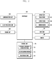
- FIG. 2 is a block diagram illustrating a configuration of a portable electronic device according to an embodiment of the present disclosure.
- the portable electronic device 100 may include a communication unit 110, an input unit 120, an audio processing unit 130, a camera 140, a sensor unit 150, a display unit 160, a storage unit 170 and a controller 180.
- the communication unit 110 may be added when the portable electronic device 100 supports a communication function, and may be omitted when the portable electronic device 100 does not support the communication function.
- the communication unit 110 may be activated when an item prepared to support the communication function by using the electronic pen 200 has been selected, and the communication unit 110 may also be activated according to a user's input by using a user's finger other than the electronic pen 200.
- the input unit 120 generates various input signals required for the operation of the portable electronic device 100.
- the input unit 120 may include various input means, such as a keyboard, a keypad, key-button, and the like, according to a possibility of exchange of the portable electronic device 100.
- the input unit 120 may also be configured with a touch map form output to the touch screen when the display unit 160 is provided as a touch screen.
- the input unit 120 may generate input signals for activating the operation of the electronic pen 200 or input signals deactivating the operation of the electronic pen 200 according to a user's request.
- the input unit 120 may produce input signals for converting a left-hand input mode and a right-hand input mode of the electronic pen 200 based on the user's request, and may transmit the input signal to the controller 180.
- the audio processing unit 130 may output various audio data configured in an operating process of the portable electronic device 100, audio data according to an audio reproduction file stored in the storage unit 170, and audio data received from outside, and the like.
- the audio processing unit 130 may support an audio data collecting function.
- the audio processing unit 130 may include a speaker and a microphone.
- the audio processing unit 130 may output guiding sounds or effect sounds corresponding thereto.
- the audio processing unit 130 may output effect sounds indicating that an input signal by the electronic pen 200 is normally operated in a process of inputting a specific text or image in the display unit 160 of the portable electronic device 100, by using the electronic pen 200.
- the camera 140 may collect images including a user's face.
- the camera 140 may transmit the collected images to the controller 180 in order to calculate a coordinate correction angle required to correct a coordinate 104 of an electromagnetic induction point into a coordinate of the contact point 102 by using the electronic pen 200.
- the camera 140 may start photographing under a control of the controller 180 when the electronic pen 200 reaches a hovering state.
- the hovering state of the electronic pen 200 refers to a state where the electronic pen 200 is located at a distance from which the sensor board 166 may detect a signal generated by the electronic pen 200 until a point where the electronic pen 200 contacts the display unit 160.
- the controller 180 starts photographing the user images in the hovering state of the electronic pen 200 so that the controller 180 may previously confirm an arrangement state and a rotation angle of the portable electronic device 100 before the signal by the electronic pen 200 is input.
- a reaction speed of the graphic elements output according to the signal input of the electronic pen 200 may increase.
- the present disclosure is not limited to this embodiment, and the camera 140 according to the embodiment of the present disclosure may achieve an identical object even though the photographing is started after the input by the electronic pen 200.
- the controller 180 may recognize the user's face from images including the user's face and extract specific coordinate of an eye, a nose, a face shape, and the like of the user, as feature points of the user, from the recognized user face.
- the controller 180 may confirm a angle in which the portable electronic device 100 inclines in the right and left directions on the basis of a front of user by using coordinates of the two eyes of the user, which are extracted as specific coordinates, and then calculate coordinate correction angles by using the obtained result.
- the display unit 160 provides various pictures required for an operation of the portable electronic device 100.
- the display unit 160 supports a standby screen, a menu screen, and the like, which are required for the operation of the portable electronic device 100.
- the display unit 160 may differently display a screen direction according to the rotation of the portable electronic device 100 of the user.
- the display unit 160 may support a configuration screen which may determine whether the coordinate correction of the electronic pen 200 according to an embodiment of the present disclosure is applied.
- the display unit 160 may provide a configuration window which may configure a mode using the user image photographed by the camera 140, a mode using the touch hovering input and a mode using the palm touch input as a method for correcting coordinates of the electronic pen 200.
- the mode using the user image photographed by the camera 140, the mode using the touch hovering input, and the mode using the palm touch input may be configured to be overlapped under the control of the controller 180 and may be configured to have a different priority from each other when those modes are configured to be overlapped.
- the controller 180 may configure the mode for using the palm touch, the mode for using the touch hovering, the mode for using the user image in sequence.
- the display unit 160 may include a display panel 164, a touch panel 162, and a sensor board 166.
- the touch panel 162 may be formed in a full touch screen by being configured to cover a front side of the display panel 164.
- the display panel 164 may output a screen in a predetermined direction according to the operation of the user function and is supported so as to provide a screen in a transverse mode or a longitudinal mode in a specific direction according to the rotation or continuously maintain a screen state in a specific mode.
- the display panel 164 may output an input of a coordinate corrected based on the coordinate correction angles and coordinate correction distances calculated by the controller.
- the touch panel 162 may transmit a touch event according to the contact together with position information, a touch degree and period information to the controller 180.
- the touch panel 162 supports a function that may select specific configuration elements output to the screen by being matched with the screen configuration elements output to the display panel 164.
- the touch panel 162 may receive the touch hovering input and the palm touch input in order to correct the coordinate of the electronic pen 200.
- the touch panel 162 may receive a touch hovering input generated by a hand of the user who grasps the electronic pen 200 and transmit the touch hovering input to the controller 180.
- the controller 180 may confirm the coordinate of the touch hovering input based on the transmitted touch hovering input.
- the controller 180 may determine the coordinate of the touch hovering input by comparing the hovering intensity.
- the controller 180 may calculate the coordinate correction angles by using the coordinate of the calculated touch hovering input and the coordinate of the electromagnetic induction point 104.
- the touch panel 162 may also receive a palm touch input of the user who grasps the electronic pen 200.
- the touch panel 162 may transmit the received palm touch input to the controller 180.
- the controller 180 may calculate a center point of the palm touch input among a plurality of points based on the palm touch input.
- a formula for calculating the center point of the palm touch input may include calculating coordinates obtained by averaging vector values of the points corresponding to an outline of a palm touch area among coordinates of the points configured in an area formed by the palm touch, as the center point.
- the formula for calculating the center point is merely illustrative; embodiments of the present disclosure are not limited to this formula, and various center point calculating formulae may be applied.
- the controller 180 may calculate the coordinate correction angles by using coordinates of a center point of the calculated palm touch input and coordinates of the electromagnetic induction point 104 of the electronic pen 200.
- the controller 180 may utilize a distance between the center point of the palm touch and the electromagnetic induction point 104 of the electronic pen 200 to determine a coordinate correction distance so as to correct distance errors according to inclination of the electronic pen 200.
- the sensor board 166 is arranged below the display panel 164 and supports an electromagnetic induction by a coil 230 included in the electronic pen 200. In this event, the sensor board 166 may supply a predetermined electric voltage or electric current to the front side of the board according to the control of the controller 180 to detect the electromagnetic induction of the coil 230 and the induced electromagnetism.
- the sensor board 166 may have a size corresponding to the whole display panel 164.
- the sensor board 166 may have a size smaller than the size of the display panel 164.
- the sensor board 166 may generate a signal and transmit the signal to the controller 180 when the electronic pen 200 approaches the portable electronic device 100 and reaches a distance by which the hovering may be detected.
- the controller 180 may control the camera 140 to be activated in order to photograph the user.
- the storage unit 170 is a secondary memory unit of the controller 180, and may include a disc, a RAM, and a flash memory.
- the storage unit 170 may store data generated from the portable electronic device 100 under the control of the controller 180 or received from an outer device, such as a server, a desktop Personal Computer (PC), and the like, through the communication unit 110 or an external interface unit (not shown).
- the storage unit 170 may include a standard coordinate correction table 172, a face recognition program 174, and a palm touch table 176.
- the standard coordinate correction table 172 may store values such as a grip angle of the left-hand, a grip angle of the right-hand, a standard inclination correction distance, and the like, which are defined for the coordinate correction of the electronic pen 200.
- the grip angle of the left-hand, the grip angle of the right-hand, and the standard inclination correction distance may be generally determined as values obtained through statistics and may be set by a designer or a user at the time of the design.
- the controller 180 may identify the inclination angle of the portable electronic device 100 in the right and left directions through face recognition, and calculate a coordinate correction angle by adding or subtracting the grip angle of the left-hand or the grip angle of the right-hand together with the inclination angle of the portable electronic device 100 in the right and left directions.
- the controller 180 may also determine the correction coordinate, which is a coordinate for correcting from the electromagnetic induction point 104 to the contact point 102 of the electronic pen 200, by using the standard inclination correction distance when the coordinate correction angle has been calculated.
- the face recognition program 174 may generate the coordinate correction angle by using the photographed user image.
- the face recognition system 174 may recognize a face of the user included in the image photographed by the camera 140 and extract a specific coordinate of an eye or a nose or the like from the recognized face.
- the face recognition program 174 may extract coordinates for two eyes of the user as a feature point.
- the controller 180 may receive the coordinates of two eyes of the user, which are extracted from the face recognition program 174, and calculate a rotation angle of the portable electronic device 100 from the received coordinates of two eyes of the user.
- the controller 180 may identify an arrangement state of the portable electronic device 100 from the recognized face of the user.
- the controller 180 may calculate a coordinate correction angle by using the inclination angle of the portable electronic device 100, which includes the calculated arrangement state and rotation angle of the portable electronic device 100, in right and left directions.
- a palm touch table 176 is a table in which a coordinate correction distance has been previously defined to correct distance errors according to the inclination angle of the electronic pen 200.
- the inclination angle of the electronic pen 200 may be continuously changed as the user takes notes on the display unit 160 by using the electronic pen 200.
- the controller 180 may correct coordinates by reflecting the inclination angles of the electronic pen 200, which is continuously changed, by using the palm input of the user (i.e., the palm touch input), with respect to the display unit 160 by means of the palm touch table 176.
- the touch panel 162 may transmit the palm touch input to the controller 180.
- the controller 180 may confirm coordinates of a center point of the palm touch input based on the received palm touch input.
- the controller 180 may calculate a distance between a coordinate of a contact point according to a contact of the electronic pen 200 with the display unit 160 and a coordinate of the identified center point.
- the controller 180 may determine a coordinate correction distance of the electronic pen 200 through the palm touch table 176 in which a distance corresponding to a distance between the coordinate of the calculated contact point and the coordinate of the center point is previously defined.
- the storage unit 170 may also store an Operating System (OS) for operating the portable electronic device 100; an application program required for other optional functions, such as a sound reproduction function, an image or video reproduction function, a broadcast reproduction function, and the like; user data; data transmitted and received at the time of the communication; and the like.
- OS Operating System
- the storage unit 170 may store a coordinate correction program of the electronic pen 200.
- the coordinate correction program of the electronic pen 200 may include a routine in which, when an input of the face image of the user is received, a coordinate correction angle is produced by using an eye coordinate extracted from the received face image of the user; a routine in which, when the touch hovering input is received, a coordinate correction angle is calculated by using the coordinate of the electromagnetic induction point 104 of the electronic pen 200 and the coordinate of the touch hovering input; and a routine in which, when the palm touch input is received, a coordinate correction angle and a coordinate correction distance is calculated by using the coordinate of the electromagnetic induction point 104 of the electronic pen 200, and the coordinate of the palm touch input.
- FIG. 3 is a flowchart illustrating a method for correcting a coordinate of an electronic pen using face recognition according to an embodiment of the present disclosure
- FIG. 4 is a view illustrating a method for correcting a coordinate of an electronic pen using face recognition according to an embodiment of the present disclosure.
- the controller 180 activates a function of the electronic pen 200.
- the controller 180 controls each element of the portable electronic device 100 to perform a user function by using the supplied power, receives a function activation signal of the electronic pen 200 from the input unit 120, and the like, and activates the function of the electronic pen 200.
- the controller 180 starts photographing when detecting a hovering state of the electronic pen 200 so that a reaction velocity of a signal output of the electronic pen 200 may increase.
- the scope of the technical idea of the present disclosure is not limited thereto, and the camera 140 may achieve an identical object while starting photographing after the input by the electronic pen 200.
- the controller 180 recognizes a face from the received user image and extracts a feature point.
- the controller 180 may recognize a user face by using the face recognition program 174 included in the user image.
- the controller 180 may extract a coordinate of the feature point from the recognized face.
- the feature point may include an eye, a nose, or the like of the recognized face.
- embodiments of the present disclosure may include other face portions to be recognized, such as a lip, a face shape, or the like, other than the eye or the nose of the recognized face and may recognize an angle of a face.
- the controller 180 may use coordinates of two eyes of the user as the coordinate of a feature point.
- the controller 180 does not recognize the user face from a collected image. For example, when the user face is not photographed or a part of the user face is only photographed within a scope of the photographing of the camera 140, the controller 180 may not recognize the user face. In this event, the controller 180 may control to limit a number of photographs of the user image within a predetermined number and to correct the errors of the electronic pen 200 by using the grip angle ⁇ of the right-hand or the left-hand and the standard inclination distance when the user face is not recognized within a predetermined time.
- the controller 180 identifies the inclination angle of the portable electronic device 100 in the right and left directions, including an arrangement state and a rotation angle of the portable electronic device 100 by using extracted coordinates 410 and 420 of the two eyes and the recognized user face.
- a reference numeral 401 illustrates a state wherein the portable electronic device 100 is arranged in a forward directional transverse mode on the basis of a front side of the user.
- the portable electronic device 100 when the portable electronic device 100 is in an inclined state by a predetermined angle with respect to the ground, the portable electronic device 100 may be identified as being in the forward directional transverse mode through an acceleration sensor, a geomagnetism sensor, and a gyro sensor, and the like included in the sensor unit 150.
- the arrangement state of the portable electronic device 100 may not be identified. Accordingly, when the controller 180 recognizes the arrangement state of the portable electronic device 100 to be in a different mode from the forward directional transverse mode and applies the grip angle ⁇ of the right-hand as a coordinate correction angle of the electronic pen 200, errors become larger.
- reference numeral 402 illustrates that the portable electronic device 100 is rotated at a predetermined angle A in order to calculate the coordinate correction angle of the electronic pen 200 by using the coordinates 410 and 420 of the two eyes from the image 430 including the user face. While the coordinates of the two eyes of the user do not change on the basis of the front side of the user according to the rotation of the portable electronic device 100, a coordinate on the display unit 160 of the portable electronic device 100 may be changed. In reference numeral 402, the image 430 including the user face shown by a dotted line does not output actually on the display unit 160.
- the controller 180 may identify the arrangement state of the portable electronic device 100 by recognizing the user face.
- the controller 180 may recognize the arrangement state of the portable electronic device 100 as the forward directional transverse mode in reference numeral 402 through two eyes, a nose, a face portion, a lip, and the like recognized from the user face. Further, the controller 180 may identify the extracted coordinates 410 and 420 of the two eyes of the user so that the rotation angle of the portable electronic device 100 may be identified. In reference numeral 402, the controller 180 may identify a rotation angle A of the portable electronic device 100 on the basis of the front side of the user by using a distance between the coordinates of two eyes of the user and a distance between the coordinates 410 and 420 of two eyes of the user with respect to a transverse axis and a longitudinal axis of the portable electronic device 100.
- the controller 180 may calculate a correction angle of the electronic pen 200 based on the arrangement state and the rotation angle of the portable electronic device 100.
- Reference numeral 403 is a view showing the portable electronic device 100 rotated by a predetermined angle A on the basis of the coordinate of the portable electronic device 100 for convenience of description.
- the forward directional transverse mode may be a standard of the coordinate of the portable electronic device 100.
- the controller 180 may calculate the coordinate correction angle of the electronic pen 200 in the forward directional transverse mode of the portable electronic device 100 as an angle ⁇ -A obtained by subtracting the rotation angle A of the portable electronic device 100 from the grip angle ⁇ of the right-hand.
- the controller 180 may correct the coordinate of the electronic pen 200 by applying the calculated coordinate correction angle and the standard inclination distance as a coordinate correction distance.
- FIG. 5 is a flowchart illustrating a method for correcting a coordinate of an electronic pen using a touch hovering according to another embodiment of the present disclosure
- FIG. 6 is a view illustrating a method for correcting a coordinate of an electronic pen using a touch hovering according to another embodiment of the present disclosure.
- the controller 180 activates a function of the electronic pen 200.
- the controller 180 controls each element of the portable electronic device 100 to perform a user function by using the supplied power, receives a function activation signal of the electronic pen 200 from the input unit 120, and the like, and activates the function of the electronic pen 200.
- the controller 180 determines whether a touch hovering input is received when an input of the electronic pen 200 has been received.
- the touch hovering is separated with the hovering state of the electronic pen 200, and indicates that a hand of the user is within a predetermined distance that may be detected from the touch panel 162 before the hand of the user touches the display unit 160 when the user grasps the electronic pen 200 and writes text, and the like.
- the touch hovering input is formed as an area 610 and may be detected as a coordinate from a plurality of points.
- the controller 180 may determine a touch hovering input coordinate by comparing an intensity of the hovering at a coordinate of a multiple point in which the hovering is detected.
- the controller 180 previously defines a predetermined time and may determine whether the touch hovering input is detected within the predetermined time.
- the controller 180 may apply either the left-hand or the right-hand grip angle as the coordinate correction angle which is stored in the standard coordinate correction table 172 in operation S505.
- the controller 180 may calculate a coordinate correction angle of the electronic pen 200 from the touch hovering coordinate in operation S507.
- the coordinate correction angle may be calculated regardless of the arrangement angle and the rotation angle of the portable electronic device 100, differently from the case of face recognition as described above. Even though the portable electronic device 100 rotates at a predetermined angle B in reference numeral 602, a coordinate 104 of the electromagnetic induction point and a determined coordinate 620 of the touch hovering, which are required to calculate a coordinate correction angle C, may be obtained so that the coordinate correction angle C may be calculated.
- an angle formed by the contact point 102 of the electronic pen 200 and the electromagnetic induction point 104 is parallel with an angle formed by the electromagnetic induction point 104 and the coordinate 620 of the touch hovering, this is merely to explain the technical idea of the present disclosure and the scope of the present disclosure is not limited thereto.
- the controller 180 may determine the angle C calculated based on the coordinate 104 of the electromagnetic induction point and the coordinate 620 of the touch hovering as the coordinate correction angle, it is also possible to determine the coordinate correction angle by adding or subtracting a predetermined angle obtained through statistics or experiments to the calculated angle C.
- the controller 180 may correct the coordinate of the electronic pen 200 by applying the coordinate correcting angle and the standard inclination distance calculated in operation S507, as the coordinate correction distance.
- FIG. 7 is a flowchart illustrating a method for correcting a coordinate of an electronic pen using a palm touch according to another embodiment of the present disclosure
- FIG. 8 is a view illustrating a method for correcting a coordinate of an electronic pen using a palm touch according to another embodiment of the present disclosure.
- the controller 180 activates a function of the electronic pen 200 in operation S701.
- the controller 180 controls each element of the portable electronic device 100 to perform a user function by using the supplied power, receives a function activation signal of the electronic pen 200 from the input unit 120, and the like, and activate the function of the electronic pen 200.
- the controller 180 determines whether an input of a palm touch is received when the input of the electronic pen 200 has been received.
- the palm touch refers to a situation where a palm of the user forms a predetermined area and makes contact with the display unit 160.
- the palm touch input may form an area 810 and may be detected as coordinates of a plurality of points.
- the controller 180 may correct the coordinate of the electronic pen 200 by using the grip angle of the left-hand and the right-hand and the standard inclination correction distance in operation S705.
- a coordinate 820 of a center point of the palm touch may be calculated in operation S707.
- the controller 180 may calculate a vector value corresponding to an average value obtained by averaging vector values of points corresponding to an outline of the palm touch area 810 among coordinates of the plurality of points forming the palm touch area 810, as the center point 820.
- the calculation criteria of the center point 820 is merely an illustrative example of the present disclosure, and the present disclosure is not limited thereto; it is possible to consider various calculation criteria of the center point 820.
- a size of a pressure by the contact within the palm touch area or an intensity of the variation of the electrostatic capacity may be measured and a point where the measured size of the pressure or intensity of the capacity is the strongest may be calculated as the center point.
- the controller 180 calculates the coordinate correction angle based on the center point 820 of the palm touch calculated through operate 707.
- a scheme of calculating the coordinate correction angle based on the center point 820 of the palm touch may be identical to a scheme of using the touch hovering as described above.
- the controller 180 may calculate a coordinate correction angle E based on the coordinate of the electromagnetic induction point 104 and the coordinate of the center point 820 of the palm touch, regardless of the rotation angle of the portable electronic device 100.
- the controller 180 may apply the coordinate correction angle by adding and subtracting a predetermined angle obtained by statistics or experiments to the calculated angle E.
- the coordinate correction distance based on the coordinate 820 of the center point is calculated.
- the controller 180 may calculate a distance between the electromagnetic induction point 104 and the center point 820 of the palm touch based on the coordinate of the electromagnetic induction point 104 and the coordinate of the center point 820 of the palm touch, and calculate the coordinate correction distance.
- the coordinate correction distance may be determined based on a distance corresponding to a distance between the electromagnetic induction point 104 and the calculated center point 820 of the palm touch.
- the coordinate of the electromagnetic induction point 104 changes (e.g., from point 104-1 to 104-2 or vice versa) according to inclination angles F and G of the electronic pen 200 so that a distance l 1 and l 2 between the electromagnetic induction point 104 and the center point 820 of the palm touch may be changed. While the center point 820 of the palm touch is illustrated as an identical point regardless of the inclination angle of the electronic pen 200 in operation S713, the coordinate of the center point 820 of the palm touch may be also changed.
- a method for correcting the coordinate of an electronic pen 200 may set that a mode using the user image photographed by the camera 140, a mode using the touch hovering input, and a mode using the palm touch input are overlapped.
- a priority preference may be set.
- the controller 180 may set the priority preference as an order of the mode using the palm touch input, the mode using the touch hovering input, and the mode using the user image photographed by the camera 140.
- the coordinate correction angle and the coordinate correction distance may be calculated, the coordinate correction angle is only calculated in the mode using the touch hovering and the mode using the user image photographed by the camera 140 so that a priority may be given in the correction mode of the coordinate of the electronic pen 200 by using the palm touch.
- the mode using the touch hovering input may calculate the coordinate correction angle nevertheless separately identifying the arrangement state and the rotation angle of the portable electronic device 100, and it is possible to give the use using the touch hovering input a higher priority level than the mode using the user face image photographed by the camera 140.
- a setting of the priority preference is merely illustrative, and does not limit the technical idea of the present disclosure.
- the portable electronic device 100 may further include various additional modules according to a type of the electronic device.
- the portable electronic device 100 may further include other unmentioned configurations, such as a near distance communication module for performing near distance communication, an interface for transmitting and receiving data through a wired communication scheme or a wireless communication scheme, an internet communication module for performing an internet function by communicating with the internet network, a digital broadcasting module for performing a reproduction function and a function of digital broadcasting reception, and the like.
- the elements are not addressed in detail as they are very diversely modified according to a convergence trend of the digital devices. However, elements similar to the elements as described above may be added to the device.
- specific configurations may be omitted from the configuration or substituted with other configurations according to the types of the portable electronic device 100. This will be easily understood by those skilled in the art to which the present disclosure pertains.
- processor readable mediums examples include Read-Only Memory (ROM), Random-Access Memory (RAM), CD-ROMs, magnetic tapes, floppy disks, and optical data storage devices.
- ROM Read-Only Memory
- RAM Random-Access Memory
- CD-ROMs Compact Disc-ROMs
- magnetic tapes magnetic tapes
- floppy disks optical data storage devices.
- the processor readable mediums may also be distributed over network coupled computer systems so that the instructions are stored and executed in a distributed fashion.
- functional computer programs, instructions, and instruction segments for accomplishing the present disclosure may be easily construed by programmers skilled in the art to which the present disclosure pertains.
Landscapes
- Engineering & Computer Science (AREA)
- General Engineering & Computer Science (AREA)
- Theoretical Computer Science (AREA)
- Human Computer Interaction (AREA)
- Physics & Mathematics (AREA)
- General Physics & Mathematics (AREA)
- User Interface Of Digital Computer (AREA)
- Position Input By Displaying (AREA)
Claims (17)
- Méthode informatisée de détermination des coordonnées d'un contact sur un appareil électronique (100) à l'aide d'un stylo électronique (200), la méthode comprenant ;
le calcul (S507) d'un angle de correction de coordonnées ;
le calcul d'une distance de correction de coordonnées d'un point d'induction électromagnétique sur un écran d'affichage (160) avec un panneau tactile (162) de l'appareil électronique (100), formé par un champ électromagnétique induit par une bobine (230) incorporée dans le stylo électronique (200) sur une carte de capteur (166) incorporée dans l'appareil électronique (100) portable, jusqu'à un point de contact calculé du stylo électronique (200) sur l'écran d'affichage (160) ; et
la détermination (S509) d'une coordonnée d'un point de contact corrigé du stylo électronique (200), basé sur l'angle de correction de la coordonnée calculée et la distance de correction de la coordonnée calculée ;
le calcul (S507) de l'angle de correction de la coordonnée comprenant au moins un des suivants :calcul de l'angle de correction de la coordonnée basé sur un point correspondant à une entrée d'effleurement tactile générée par l'effleurement de la main d'un utilisateur sur l'écran d'affichage (160) et le point d'induction électromagnétique ; etcalcul de l'angle de correction de la coordonnée basé sur un point correspondant à une entrée tactile de la paume généré par le toucher de la paume de l'utilisateur sur l'écran d'affichage (160) et le point d'induction électromagnétique. - Méthode selon la revendication 1, le calcul (S507) de l'angle de correction de la coordonnée comprenant en outre le calcul (S309) de l'angle de correction de la coordonnée basé sur un angle d'inclinaison de l'appareil électronique portable (100) sur la droite ou sur la gauche, sur la base d'un côté frontal de l'utilisateur basé sur une image du visage de l'utilisateur photographiée par une caméra (140) et le point d'induction électromagnétique.
- Méthode selon la revendication 2, le calcul (S309) de l'angle de correction de la coordonnée, basé sur l'angle d'inclinaison de l'appareil électronique (100) sur la droite ou sur la gauche, sur la base d'un côté frontal de l'utilisateur basé sur l'image du visage de l'utilisateur et le point d'induction électromagnétique, comprenant :la collecte (S303) d'une image de l'utilisateur photographiée par une caméra (140) ;la reconnaissance (S305) d'une image du visage d'un utilisateur comprise dans l'image collectée de l'utilisateur ;l'extraction d'une coordonnée spécifique au sein du visage reconnu de l'utilisateur ;l'identification de l'angle d'inclinaison sur la droite ou sur la gauche, sur la base de la coordonnée spécifique et du point d'induction électromagnétique ; etle calcul de l'angle de correction de la coordonnée sur la base de l'angle d'inclinaison.
- Méthode selon la revendication 3, la collecte de l'image de l'utilisateur photographiée par une caméra (140) comprenant la photographie initiale de l'image de l'utilisateur par la caméra lors de la détection d'un effleurement du stylo électronique (200).
- Méthode selon la revendication 3, la coordonnée spécifique au sein de la face de l'utilisateur étant au moins une des suivantes : une coordonnée d'un oeil de l'utilisateur, une coordonnée d'un nez de l'utilisateur, et une coordonnée d'une forme du visage de l'utilisateur.
- Méthode selon une quelconque des revendications précédentes, le calcul (S507) de l'angle de correction des coordonnées, basé sur le point correspondant à l'entrée d'effleurement tactile et le point d'induction électromagnétique, comprenant :la détection (S503) de l'entrée d'effleurement tactile lorsque le stylo électronique (200) entre en contact avec l'écran d'affichage (160) à l'aide du panneau tactile (162) ; etle calcul de l'angle de correction des coordonnées, basé sur un angle formé par le passage d'une ligne linéaire à travers le point correspondant à l'entrée d'effleurement tactile et au point d'induction électromagnétique.
- Méthode selon la revendication 2, le calcul (S709) de l'angle de correction des coordonnées, basé sur le point correspondant à l'entrée tactile de la paume générée par le toucher de la paume et le point d'induction électromagnétique, comprenant :la détection de l'entrée tactile de la paume lorsque le stylo électronique (200) entre en contact avec l'écran d'affichage (160) à l'aide du panneau tactile (162) ;le calcul (S707) d'un point central en tant que point correspondant à l'entrée tactile de la paume détectée sur l'écran d'affichage (160) ; etle calcul (S709) de l'angle de correction des coordonnées basé sur le point central et le point d'induction électromagnétique,le calcul de la distance de correction des coordonnées, comprenant le calcul de la distance de correction des coordonnées basé sur une distance entre le point central et le point d'induction électromagnétique.
- Méthode selon la revendication 2, comprenant en outre :la détermination, lors de la réception de deux ou plusieurs des suivants : image du visage de l'utilisateur, entrée d'effleurement tactile, et entrée tactile de la paume, d'une préférence prioritaire,le calcul de l'angle de correction des coordonnées et de la distance de correction des coordonnées en fonction de la préférence prioritaire.
- Appareil électronique portable (100) comprenant : une carte de capteur (166) configurée pour recevoir une entrée d'effleurement tactile et une entrée tactile d'un style électronique (200) ; un écran d'affichage (160) avec un panneau tactile (162) configuré pour recevoir une entrée d'effleurement tactile par l'effleurement de la main d'un utilisateur et une entrée tactile de la paume générée par un toucher de la paume de l'utilisateur ; et
un contrôleur (180) configuré pour :calculer (S507) un angle de correction de coordonnées ;calculer une distance de correction de coordonnées d'un point d'induction électromagnétique sur l'écran d'affichage (160) formé par un champ électromagnétique induit par une bobine (230) incorporée dans le stylo électronique (200) sur une carte de capteur (166), jusqu'à un point de contact calculé du stylo électronique (200) sur l'écran d'affichage ; etdéterminer (S509) une coordonnée d'un point de contact corrigé du stylo électronique (200), basé sur l'angle de correction de la coordonnée et la distance calculée de correction de la coordonnée ;le contrôleur (180) étant configuré pour contrôler le calcul de l'angle de correction de la coordonnée selon au moins un des suivants :calcul de l'angle de correction de la coordonnée basé sur un point correspondant à une entrée d'effleurement tactile généré par l'effleurement de la main d'un utilisateur sur l'écran d'affichage (160) et le point d'induction électromagnétique ; etcalcul de l'angle de correction de la coordonnée basé sur un point correspondant à une entrée tactile de la paume généré par le toucher de la paume de l'utilisateur sur l'écran d'affichage (160) et le point d'induction électromagnétique. - Appareil électronique portable (100) selon la revendication 9, le contrôleur (180) étant configuré en outre pour commander le calcul de l'angle de correction des coordonnées sur la base du calcul (S309) de l'angle de correction de la coordonnée basé sur un angle d'inclinaison de l'appareil électronique portable (100) sur la droite ou sur la gauche, sur la base d'un côté frontal de l'utilisateur basé sur une image du visage de l'utilisateur et le point d'induction électromagnétique, l'appareil électronique portable (100) comprenant une caméra (140) configurée pour photographier le visage d'un utilisateur.
- Appareil électronique portable (100) selon la revendication 10, le contrôleur (180) étant configuré pour :commander la collecte (S303) d'une image de l'utilisateur photographiée par la caméra (140) ;reconnaître (S305) le visage d'un utilisateur compris dans l'image collectée de l'utilisateur ;extraire une coordonnée spécifique au sein du visage reconnu de l'utilisateur ;identifier l'angle d'inclinaison sur la droite ou sur la gauche, sur la base de la coordonnée spécifique et du point d'induction électromagnétique ; etcalculer l'angle de correction de la coordonnée sur la base de l'angle d'inclinaison.
- Appareil électronique portable (100) selon la revendication 11, le contrôleur (180) étant configuré pour commander à la caméra (140) de commencer la photographie de l'image de l'utilisateur lorsqu'est détecté l'effleurement de la main de l'utilisateur saisissant le style électronique (200).
- Appareil électronique portable (100) selon la revendication 10, la coordonnée spécifique au sein du visage de l'utilisateur étant au moins une des suivantes : une coordonnée d'un oeil de l'utilisateur, une coordonnée d'un nez de l'utilisateur, et une coordonnée d'une forme du visage de l'utilisateur.
- Appareil électronique portable (100) selon une quelconque des revendications 9 à 13, le contrôleur (180) étant configuré pour :détecter (S503) l'entrée d'effleurement tactile lorsque le stylo électronique (200) entre en contact avec l'écran d'affichage (160) à l'aide du panneau tactile (162) ; etcalculer l'angle de correction des coordonnées, sur la base d'un angle formé par le passage d'une ligne linéaire à travers le point correspondant à l'entrée d'effleurement tactile et au point d'induction électromagnétique.
- Appareil électronique portable (100) selon la revendication 10, le contrôleur (180) étant configuré pour :détecter l'entrée tactile de la paume lorsque le stylo électronique (200) entre en contact avec l'écran d'affichage (160) à l'aide du panneau tactile (162) ;calculer (S707) un point central en tant que point correspondant à l'entrée tactile de la paume détectée sur l'écran d'affichage (160) ;calculer (S709) l'angle de correction des coordonnées basé sur le point central et le point d'induction électromagnétique ;calculer (S711) la distance de correction des coordonnées basée sur une distance entre le point central et le point d'induction électromagnétique ; etcalculer (S713) la distance de correction des coordonnées basée sur une distance entre le point central et le point d'induction électromagnétique.
- Appareil électronique portable (100) selon la revendication 10, le contrôleur (180) étant configuré en outre pour :déterminer, lors de l'entrée de deux ou plusieurs des suivants : image du visage de l'utilisateur,entrée d'effleurement tactile, et entrée tactile de la paume, d'une préférence prioritaire, etcalculer l'angle de correction des coordonnées et de la distance de correction des coordonnées en fonction de la préférence prioritaire.
- Support de stockage non transitoire lisible par ordinateur stockant des instructions qui, lors de leur exécution sur l'appareil électronique portable selon une quelconque des revendications 9 à 16, détermine l'exécution, par au moins un processeur, de la méthode selon une quelconque des revendications 1 à 8.
Applications Claiming Priority (1)
| Application Number | Priority Date | Filing Date | Title |
|---|---|---|---|
| KR1020130063942A KR102109649B1 (ko) | 2013-06-04 | 2013-06-04 | 전자 펜 좌표 보정 방법 및 이를 지원하는 휴대형 전자장치 |
Publications (3)
| Publication Number | Publication Date |
|---|---|
| EP2811373A2 EP2811373A2 (fr) | 2014-12-10 |
| EP2811373A3 EP2811373A3 (fr) | 2015-10-28 |
| EP2811373B1 true EP2811373B1 (fr) | 2019-01-02 |
Family
ID=51032894
Family Applications (1)
| Application Number | Title | Priority Date | Filing Date |
|---|---|---|---|
| EP14168518.0A Not-in-force EP2811373B1 (fr) | 2013-06-04 | 2014-05-15 | Procédé pour corriger des coordonnées d'un dispositif électronique portatif utilisant un stylo électronique |
Country Status (3)
| Country | Link |
|---|---|
| US (1) | US9262028B2 (fr) |
| EP (1) | EP2811373B1 (fr) |
| KR (1) | KR102109649B1 (fr) |
Families Citing this family (23)
| Publication number | Priority date | Publication date | Assignee | Title |
|---|---|---|---|---|
| KR20130136276A (ko) * | 2012-06-04 | 2013-12-12 | 삼성전자주식회사 | 단말기의 펜 입력 보정장치 및 방법 |
| KR102169952B1 (ko) * | 2013-10-18 | 2020-10-26 | 엘지전자 주식회사 | 웨어러블 디바이스 및 그 제어 방법 |
| KR102241764B1 (ko) * | 2013-11-01 | 2021-04-19 | 삼성전자 주식회사 | 전자 장치의 입력 처리 방법 및 장치 |
| US10345927B2 (en) * | 2014-06-11 | 2019-07-09 | Lenovo (Singapore) Pte. Ltd. | Pen/stylus offset modification |
| CN105630270B (zh) * | 2014-10-30 | 2019-03-29 | 联想(北京)有限公司 | 一种信息处理方法、装置和电子设备 |
| KR101672731B1 (ko) * | 2015-01-20 | 2016-11-04 | 주식회사 트레이스 | 펜의 기울기 정보를 이용하여 3d 호버링 인식이 가능한 디지타이저 시스템 |
| KR102338712B1 (ko) * | 2015-09-24 | 2021-12-13 | 엘지디스플레이 주식회사 | 능동형 터치 펜과 그를 포함한 터치 센싱 시스템, 및 그 구동방법 |
| KR102589452B1 (ko) | 2016-07-29 | 2023-10-16 | 삼성전자주식회사 | 펜 입력 처리 방법 및 이를 지원하는 전자 장치 |
| USD861688S1 (en) * | 2017-08-25 | 2019-10-01 | Samsung Electronics Co., Ltd. | E-board pen |
| CN110851014B (zh) * | 2019-10-29 | 2023-08-18 | Tcl移动通信科技(宁波)有限公司 | 触摸识别方法、装置、存储介质及终端设备 |
| CN111273812A (zh) * | 2020-01-15 | 2020-06-12 | 深圳市华星光电半导体显示技术有限公司 | 屏幕触控定位的方法及定位系统 |
| US11869213B2 (en) * | 2020-01-17 | 2024-01-09 | Samsung Electronics Co., Ltd. | Electronic device for analyzing skin image and method for controlling the same |
| WO2021161701A1 (fr) * | 2020-02-10 | 2021-08-19 | 株式会社ワコム | Procédé de détection de position de pointeur et organe de commande de capteur |
| KR20220074053A (ko) | 2020-11-27 | 2022-06-03 | 삼성전자주식회사 | 전자 장치 및 전자 장치에서 스타일러스 펜의 에어 포인터를 제어하기 위한 방법 |
| KR20230079976A (ko) * | 2021-11-29 | 2023-06-07 | 삼성전자주식회사 | 변형 가능한 디스플레이를 포함하는 전자 장치 및 이의 동작 방법 |
| US11537239B1 (en) * | 2022-01-14 | 2022-12-27 | Microsoft Technology Licensing, Llc | Diffusion-based handedness classification for touch-based input |
| CN114459434A (zh) * | 2022-01-28 | 2022-05-10 | 青岛罗博科技有限公司 | 一种点阵笔倾角检测方法、系统及电子设备 |
| KR102478738B1 (ko) | 2022-05-24 | 2022-12-19 | 주식회사 보나 | 광 산란 기반의 광학식 전자펜 |
| KR102472784B1 (ko) | 2022-05-27 | 2022-12-01 | 주식회사 보나 | 자이로 센서 기반의 광학식 전자펜의 호버링 처리 방법 |
| KR102429967B1 (ko) | 2022-06-02 | 2022-08-05 | 주식회사 보나 | 자이로 센서 기반의 광학식 전자펜의 디스플레이 엣지 처리 시스템 및 방법 |
| KR102446916B1 (ko) | 2022-06-03 | 2022-09-23 | 주식회사 보나 | 광융착 광파이버를 이용한 광 산란 기반의 광학식 전자펜 |
| KR102486202B1 (ko) | 2022-09-15 | 2023-01-10 | 주식회사 보나 | 광 산란제 펜팁을 구비한 광학식 전자펜 |
| KR102476025B1 (ko) | 2022-10-13 | 2022-12-09 | 주식회사 보나 | 광학식 전자펜을 위한 그래픽 인디케이터 장치 및 그 이미지 처리 방법 |
Family Cites Families (8)
| Publication number | Priority date | Publication date | Assignee | Title |
|---|---|---|---|---|
| US4577057A (en) | 1984-03-02 | 1986-03-18 | Pencept, Inc. | Digitizing tablet system having stylus tilt correction |
| JPS6370326A (ja) | 1986-09-12 | 1988-03-30 | Wacom Co Ltd | 位置検出装置 |
| JP2006302029A (ja) | 2005-04-21 | 2006-11-02 | Fuji Xerox Co Ltd | 表示装置制御プログラム、表示装置制御方法、表示装置 |
| JP2011164746A (ja) | 2010-02-05 | 2011-08-25 | Seiko Epson Corp | 端末装置、持ち手検出方法、及びプログラム |
| TWI414979B (zh) | 2010-08-16 | 2013-11-11 | Waltop Int Corp | 手寫輸入裝置及其角度校正方法 |
| US20120206419A1 (en) * | 2011-02-11 | 2012-08-16 | Massachusetts Institute Of Technology | Collapsible input device |
| KR20130034765A (ko) | 2011-09-29 | 2013-04-08 | 삼성전자주식회사 | 휴대 단말기의 펜 입력 방법 및 장치 |
| US9261985B2 (en) * | 2013-03-11 | 2016-02-16 | Barnes & Noble College Booksellers, Llc | Stylus-based touch-sensitive area for UI control of computing device |
-
2013
- 2013-06-04 KR KR1020130063942A patent/KR102109649B1/ko active IP Right Grant
-
2014
- 2014-05-15 EP EP14168518.0A patent/EP2811373B1/fr not_active Not-in-force
- 2014-05-15 US US14/278,492 patent/US9262028B2/en not_active Expired - Fee Related
Non-Patent Citations (1)
| Title |
|---|
| None * |
Also Published As
| Publication number | Publication date |
|---|---|
| EP2811373A3 (fr) | 2015-10-28 |
| KR20140142778A (ko) | 2014-12-15 |
| EP2811373A2 (fr) | 2014-12-10 |
| KR102109649B1 (ko) | 2020-05-13 |
| US20140354589A1 (en) | 2014-12-04 |
| US9262028B2 (en) | 2016-02-16 |
Similar Documents
| Publication | Publication Date | Title |
|---|---|---|
| EP2811373B1 (fr) | Procédé pour corriger des coordonnées d'un dispositif électronique portatif utilisant un stylo électronique | |
| EP2813938B1 (fr) | Appareil et procédé de sélection d'objet par contact multipoints et support d'enregistrement lisible par ordinateur | |
| EP3350679B1 (fr) | Dispositif électronique et procédé de traitement de gestes associé | |
| KR102170321B1 (ko) | 파지된 물체를 이용한 모션을 인식하는 장치 및 방법, 시스템 | |
| EP3046002A1 (fr) | Dispositif d'entrée virtuel et procédé permettant de recevoir une entrée utilisateur à l'aide de celui-ci | |
| EP2799971B1 (fr) | Procédé d'exploitation d'écran tactile et son dispositif électronique | |
| US9081424B2 (en) | Input device error compensating method and terminal for supporting the same | |
| US9378427B2 (en) | Displaying handwritten strokes on a device according to a determined stroke direction matching the present direction of inclination of the device | |
| US20170277273A1 (en) | Device Interaction with Spatially Aware Gestures | |
| KR102057531B1 (ko) | 제스처를 이용하여 데이터를 송수신하는 모바일 기기들 | |
| EP3062208A1 (fr) | Dispositif électronique et son procédé de contrôle | |
| KR20200028771A (ko) | 사용자 의도 기반 제스처 인식 방법 및 장치 | |
| WO2014112132A1 (fr) | Appareil d'informations et procédé de traitement d'informations | |
| EP2746924A2 (fr) | Procédé d'entrée tactile et terminal mobile | |
| US10514844B2 (en) | Automatically modifying an input area based on a proximity to one or more edges | |
| EP2703981B1 (fr) | Appareil mobile ayant une fonction d'écriture manuelle par contact multipoints et son procédé de commande | |
| EP2703978B1 (fr) | Appareil de mesure de coordonnées et procédé de commande de celui-ci | |
| CN114531501A (zh) | 控制显示的方法和支持其的电子装置 | |
| CN107272892A (zh) | 一种虚拟触控系统、方法及装置 | |
| EP2876577A1 (fr) | Dispositif électronique et procédé pour la reconnaissance de caractères dans un dispositif électronique | |
| CN106598422B (zh) | 混合操控方法及操控系统和电子设备 | |
| US20150002420A1 (en) | Mobile terminal and method for controlling screen | |
| US20140258923A1 (en) | Apparatus and method for displaying screen image | |
| JP7280888B2 (ja) | 電子機器確定方法、システム、コンピュータシステムおよび読取り可能な記憶媒体 | |
| CN110162251A (zh) | 图像缩放方法及装置、存储介质、电子设备 |
Legal Events
| Date | Code | Title | Description |
|---|---|---|---|
| PUAI | Public reference made under article 153(3) epc to a published international application that has entered the european phase |
Free format text: ORIGINAL CODE: 0009012 |
|
| 17P | Request for examination filed |
Effective date: 20140515 |
|
| AK | Designated contracting states |
Kind code of ref document: A2 Designated state(s): AL AT BE BG CH CY CZ DE DK EE ES FI FR GB GR HR HU IE IS IT LI LT LU LV MC MK MT NL NO PL PT RO RS SE SI SK SM TR |
|
| AX | Request for extension of the european patent |
Extension state: BA ME |
|
| RIC1 | Information provided on ipc code assigned before grant |
Ipc: G06F 3/0354 20130101AFI20150522BHEP Ipc: G06F 3/041 20060101ALI20150522BHEP |
|
| PUAL | Search report despatched |
Free format text: ORIGINAL CODE: 0009013 |
|
| AK | Designated contracting states |
Kind code of ref document: A3 Designated state(s): AL AT BE BG CH CY CZ DE DK EE ES FI FR GB GR HR HU IE IS IT LI LT LU LV MC MK MT NL NO PL PT RO RS SE SI SK SM TR |
|
| AX | Request for extension of the european patent |
Extension state: BA ME |
|
| RIC1 | Information provided on ipc code assigned before grant |
Ipc: G06F 3/041 20060101ALI20150923BHEP Ipc: G06F 3/0354 20130101AFI20150923BHEP |
|
| R17P | Request for examination filed (corrected) |
Effective date: 20160428 |
|
| RBV | Designated contracting states (corrected) |
Designated state(s): AL AT BE BG CH CY CZ DE DK EE ES FI FR GB GR HR HU IE IS IT LI LT LU LV MC MK MT NL NO PL PT RO RS SE SI SK SM TR |
|
| GRAP | Despatch of communication of intention to grant a patent |
Free format text: ORIGINAL CODE: EPIDOSNIGR1 |
|
| STAA | Information on the status of an ep patent application or granted ep patent |
Free format text: STATUS: GRANT OF PATENT IS INTENDED |
|
| INTG | Intention to grant announced |
Effective date: 20180710 |
|
| GRAS | Grant fee paid |
Free format text: ORIGINAL CODE: EPIDOSNIGR3 |
|
| GRAA | (expected) grant |
Free format text: ORIGINAL CODE: 0009210 |
|
| STAA | Information on the status of an ep patent application or granted ep patent |
Free format text: STATUS: THE PATENT HAS BEEN GRANTED |
|
| AK | Designated contracting states |
Kind code of ref document: B1 Designated state(s): AL AT BE BG CH CY CZ DE DK EE ES FI FR GB GR HR HU IE IS IT LI LT LU LV MC MK MT NL NO PL PT RO RS SE SI SK SM TR |
|
| REG | Reference to a national code |
Ref country code: GB Ref legal event code: FG4D |
|
| REG | Reference to a national code |
Ref country code: CH Ref legal event code: EP Ref country code: AT Ref legal event code: REF Ref document number: 1085206 Country of ref document: AT Kind code of ref document: T Effective date: 20190115 |
|
| REG | Reference to a national code |
Ref country code: IE Ref legal event code: FG4D |
|
| REG | Reference to a national code |
Ref country code: DE Ref legal event code: R096 Ref document number: 602014038972 Country of ref document: DE |
|
| REG | Reference to a national code |
Ref country code: NL Ref legal event code: FP |
|
| REG | Reference to a national code |
Ref country code: LT Ref legal event code: MG4D |
|
| REG | Reference to a national code |
Ref country code: AT Ref legal event code: MK05 Ref document number: 1085206 Country of ref document: AT Kind code of ref document: T Effective date: 20190102 |
|
| PG25 | Lapsed in a contracting state [announced via postgrant information from national office to epo] |
Ref country code: SE Free format text: LAPSE BECAUSE OF FAILURE TO SUBMIT A TRANSLATION OF THE DESCRIPTION OR TO PAY THE FEE WITHIN THE PRESCRIBED TIME-LIMIT Effective date: 20190102 Ref country code: PL Free format text: LAPSE BECAUSE OF FAILURE TO SUBMIT A TRANSLATION OF THE DESCRIPTION OR TO PAY THE FEE WITHIN THE PRESCRIBED TIME-LIMIT Effective date: 20190102 Ref country code: ES Free format text: LAPSE BECAUSE OF FAILURE TO SUBMIT A TRANSLATION OF THE DESCRIPTION OR TO PAY THE FEE WITHIN THE PRESCRIBED TIME-LIMIT Effective date: 20190102 Ref country code: LT Free format text: LAPSE BECAUSE OF FAILURE TO SUBMIT A TRANSLATION OF THE DESCRIPTION OR TO PAY THE FEE WITHIN THE PRESCRIBED TIME-LIMIT Effective date: 20190102 Ref country code: NO Free format text: LAPSE BECAUSE OF FAILURE TO SUBMIT A TRANSLATION OF THE DESCRIPTION OR TO PAY THE FEE WITHIN THE PRESCRIBED TIME-LIMIT Effective date: 20190402 Ref country code: FI Free format text: LAPSE BECAUSE OF FAILURE TO SUBMIT A TRANSLATION OF THE DESCRIPTION OR TO PAY THE FEE WITHIN THE PRESCRIBED TIME-LIMIT Effective date: 20190102 Ref country code: PT Free format text: LAPSE BECAUSE OF FAILURE TO SUBMIT A TRANSLATION OF THE DESCRIPTION OR TO PAY THE FEE WITHIN THE PRESCRIBED TIME-LIMIT Effective date: 20190502 |
|
| PG25 | Lapsed in a contracting state [announced via postgrant information from national office to epo] |
Ref country code: IS Free format text: LAPSE BECAUSE OF FAILURE TO SUBMIT A TRANSLATION OF THE DESCRIPTION OR TO PAY THE FEE WITHIN THE PRESCRIBED TIME-LIMIT Effective date: 20190502 Ref country code: GR Free format text: LAPSE BECAUSE OF FAILURE TO SUBMIT A TRANSLATION OF THE DESCRIPTION OR TO PAY THE FEE WITHIN THE PRESCRIBED TIME-LIMIT Effective date: 20190403 Ref country code: BG Free format text: LAPSE BECAUSE OF FAILURE TO SUBMIT A TRANSLATION OF THE DESCRIPTION OR TO PAY THE FEE WITHIN THE PRESCRIBED TIME-LIMIT Effective date: 20190402 Ref country code: RS Free format text: LAPSE BECAUSE OF FAILURE TO SUBMIT A TRANSLATION OF THE DESCRIPTION OR TO PAY THE FEE WITHIN THE PRESCRIBED TIME-LIMIT Effective date: 20190102 Ref country code: LV Free format text: LAPSE BECAUSE OF FAILURE TO SUBMIT A TRANSLATION OF THE DESCRIPTION OR TO PAY THE FEE WITHIN THE PRESCRIBED TIME-LIMIT Effective date: 20190102 Ref country code: HR Free format text: LAPSE BECAUSE OF FAILURE TO SUBMIT A TRANSLATION OF THE DESCRIPTION OR TO PAY THE FEE WITHIN THE PRESCRIBED TIME-LIMIT Effective date: 20190102 |
|
| REG | Reference to a national code |
Ref country code: DE Ref legal event code: R097 Ref document number: 602014038972 Country of ref document: DE |
|
| PG25 | Lapsed in a contracting state [announced via postgrant information from national office to epo] |
Ref country code: AL Free format text: LAPSE BECAUSE OF FAILURE TO SUBMIT A TRANSLATION OF THE DESCRIPTION OR TO PAY THE FEE WITHIN THE PRESCRIBED TIME-LIMIT Effective date: 20190102 Ref country code: RO Free format text: LAPSE BECAUSE OF FAILURE TO SUBMIT A TRANSLATION OF THE DESCRIPTION OR TO PAY THE FEE WITHIN THE PRESCRIBED TIME-LIMIT Effective date: 20190102 Ref country code: CZ Free format text: LAPSE BECAUSE OF FAILURE TO SUBMIT A TRANSLATION OF THE DESCRIPTION OR TO PAY THE FEE WITHIN THE PRESCRIBED TIME-LIMIT Effective date: 20190102 Ref country code: SK Free format text: LAPSE BECAUSE OF FAILURE TO SUBMIT A TRANSLATION OF THE DESCRIPTION OR TO PAY THE FEE WITHIN THE PRESCRIBED TIME-LIMIT Effective date: 20190102 Ref country code: EE Free format text: LAPSE BECAUSE OF FAILURE TO SUBMIT A TRANSLATION OF THE DESCRIPTION OR TO PAY THE FEE WITHIN THE PRESCRIBED TIME-LIMIT Effective date: 20190102 Ref country code: DK Free format text: LAPSE BECAUSE OF FAILURE TO SUBMIT A TRANSLATION OF THE DESCRIPTION OR TO PAY THE FEE WITHIN THE PRESCRIBED TIME-LIMIT Effective date: 20190102 Ref country code: AT Free format text: LAPSE BECAUSE OF FAILURE TO SUBMIT A TRANSLATION OF THE DESCRIPTION OR TO PAY THE FEE WITHIN THE PRESCRIBED TIME-LIMIT Effective date: 20190102 Ref country code: IT Free format text: LAPSE BECAUSE OF FAILURE TO SUBMIT A TRANSLATION OF THE DESCRIPTION OR TO PAY THE FEE WITHIN THE PRESCRIBED TIME-LIMIT Effective date: 20190102 |
|
| PLBE | No opposition filed within time limit |
Free format text: ORIGINAL CODE: 0009261 |
|
| STAA | Information on the status of an ep patent application or granted ep patent |
Free format text: STATUS: NO OPPOSITION FILED WITHIN TIME LIMIT |
|
| PG25 | Lapsed in a contracting state [announced via postgrant information from national office to epo] |
Ref country code: SM Free format text: LAPSE BECAUSE OF FAILURE TO SUBMIT A TRANSLATION OF THE DESCRIPTION OR TO PAY THE FEE WITHIN THE PRESCRIBED TIME-LIMIT Effective date: 20190102 |
|
| 26N | No opposition filed |
Effective date: 20191003 |
|
| REG | Reference to a national code |
Ref country code: CH Ref legal event code: PL |
|
| PG25 | Lapsed in a contracting state [announced via postgrant information from national office to epo] |
Ref country code: CH Free format text: LAPSE BECAUSE OF NON-PAYMENT OF DUE FEES Effective date: 20190531 Ref country code: MC Free format text: LAPSE BECAUSE OF FAILURE TO SUBMIT A TRANSLATION OF THE DESCRIPTION OR TO PAY THE FEE WITHIN THE PRESCRIBED TIME-LIMIT Effective date: 20190102 Ref country code: LI Free format text: LAPSE BECAUSE OF NON-PAYMENT OF DUE FEES Effective date: 20190531 |
|
| REG | Reference to a national code |
Ref country code: BE Ref legal event code: MM Effective date: 20190531 |
|
| PG25 | Lapsed in a contracting state [announced via postgrant information from national office to epo] |
Ref country code: SI Free format text: LAPSE BECAUSE OF FAILURE TO SUBMIT A TRANSLATION OF THE DESCRIPTION OR TO PAY THE FEE WITHIN THE PRESCRIBED TIME-LIMIT Effective date: 20190102 Ref country code: LU Free format text: LAPSE BECAUSE OF NON-PAYMENT OF DUE FEES Effective date: 20190515 |
|
| PG25 | Lapsed in a contracting state [announced via postgrant information from national office to epo] |
Ref country code: TR Free format text: LAPSE BECAUSE OF FAILURE TO SUBMIT A TRANSLATION OF THE DESCRIPTION OR TO PAY THE FEE WITHIN THE PRESCRIBED TIME-LIMIT Effective date: 20190102 |
|
| PG25 | Lapsed in a contracting state [announced via postgrant information from national office to epo] |
Ref country code: IE Free format text: LAPSE BECAUSE OF NON-PAYMENT OF DUE FEES Effective date: 20190515 |
|
| PG25 | Lapsed in a contracting state [announced via postgrant information from national office to epo] |
Ref country code: BE Free format text: LAPSE BECAUSE OF NON-PAYMENT OF DUE FEES Effective date: 20190531 |
|
| PG25 | Lapsed in a contracting state [announced via postgrant information from national office to epo] |
Ref country code: FR Free format text: LAPSE BECAUSE OF NON-PAYMENT OF DUE FEES Effective date: 20190531 |
|
| PGFP | Annual fee paid to national office [announced via postgrant information from national office to epo] |
Ref country code: NL Payment date: 20200422 Year of fee payment: 7 Ref country code: DE Payment date: 20200421 Year of fee payment: 7 |
|
| PGFP | Annual fee paid to national office [announced via postgrant information from national office to epo] |
Ref country code: GB Payment date: 20200423 Year of fee payment: 7 |
|
| PG25 | Lapsed in a contracting state [announced via postgrant information from national office to epo] |
Ref country code: CY Free format text: LAPSE BECAUSE OF FAILURE TO SUBMIT A TRANSLATION OF THE DESCRIPTION OR TO PAY THE FEE WITHIN THE PRESCRIBED TIME-LIMIT Effective date: 20190102 |
|
| PG25 | Lapsed in a contracting state [announced via postgrant information from national office to epo] |
Ref country code: MT Free format text: LAPSE BECAUSE OF FAILURE TO SUBMIT A TRANSLATION OF THE DESCRIPTION OR TO PAY THE FEE WITHIN THE PRESCRIBED TIME-LIMIT Effective date: 20190102 Ref country code: HU Free format text: LAPSE BECAUSE OF FAILURE TO SUBMIT A TRANSLATION OF THE DESCRIPTION OR TO PAY THE FEE WITHIN THE PRESCRIBED TIME-LIMIT; INVALID AB INITIO Effective date: 20140515 |
|
| REG | Reference to a national code |
Ref country code: DE Ref legal event code: R119 Ref document number: 602014038972 Country of ref document: DE |
|
| REG | Reference to a national code |
Ref country code: NL Ref legal event code: MM Effective date: 20210601 |
|
| GBPC | Gb: european patent ceased through non-payment of renewal fee |
Effective date: 20210515 |
|
| PG25 | Lapsed in a contracting state [announced via postgrant information from national office to epo] |
Ref country code: GB Free format text: LAPSE BECAUSE OF NON-PAYMENT OF DUE FEES Effective date: 20210515 Ref country code: DE Free format text: LAPSE BECAUSE OF NON-PAYMENT OF DUE FEES Effective date: 20211201 |
|
| PG25 | Lapsed in a contracting state [announced via postgrant information from national office to epo] |
Ref country code: NL Free format text: LAPSE BECAUSE OF NON-PAYMENT OF DUE FEES Effective date: 20210601 |
|
| PG25 | Lapsed in a contracting state [announced via postgrant information from national office to epo] |
Ref country code: MK Free format text: LAPSE BECAUSE OF FAILURE TO SUBMIT A TRANSLATION OF THE DESCRIPTION OR TO PAY THE FEE WITHIN THE PRESCRIBED TIME-LIMIT Effective date: 20190102 |