EP2811284A1 - Steuereinheit - Google Patents
Steuereinheit Download PDFInfo
- Publication number
- EP2811284A1 EP2811284A1 EP12867089.0A EP12867089A EP2811284A1 EP 2811284 A1 EP2811284 A1 EP 2811284A1 EP 12867089 A EP12867089 A EP 12867089A EP 2811284 A1 EP2811284 A1 EP 2811284A1
- Authority
- EP
- European Patent Office
- Prior art keywords
- temperature
- humidity
- thermostat
- controller
- humidity sensor
- Prior art date
- Legal status (The legal status is an assumption and is not a legal conclusion. Google has not performed a legal analysis and makes no representation as to the accuracy of the status listed.)
- Withdrawn
Links
- 230000007613 environmental effect Effects 0.000 claims abstract description 25
- 238000012937 correction Methods 0.000 claims abstract description 20
- 238000009826 distribution Methods 0.000 claims abstract description 20
- 238000012360 testing method Methods 0.000 description 37
- 230000001143 conditioned effect Effects 0.000 description 5
- 238000004891 communication Methods 0.000 description 4
- 230000006870 function Effects 0.000 description 4
- 238000005259 measurement Methods 0.000 description 4
- 238000000034 method Methods 0.000 description 4
- 238000010586 diagram Methods 0.000 description 2
- 239000003814 drug Substances 0.000 description 2
- 238000005070 sampling Methods 0.000 description 2
- 238000013112 stability test Methods 0.000 description 2
- 238000011017 operating method Methods 0.000 description 1
- 230000004044 response Effects 0.000 description 1
- 238000009420 retrofitting Methods 0.000 description 1
- 230000001360 synchronised effect Effects 0.000 description 1
Images


Classifications
-
- G—PHYSICS
- G05—CONTROLLING; REGULATING
- G05D—SYSTEMS FOR CONTROLLING OR REGULATING NON-ELECTRIC VARIABLES
- G05D22/00—Control of humidity
- G05D22/02—Control of humidity characterised by the use of electric means
-
- G—PHYSICS
- G01—MEASURING; TESTING
- G01N—INVESTIGATING OR ANALYSING MATERIALS BY DETERMINING THEIR CHEMICAL OR PHYSICAL PROPERTIES
- G01N17/00—Investigating resistance of materials to the weather, to corrosion, or to light
- G01N17/002—Test chambers
-
- F—MECHANICAL ENGINEERING; LIGHTING; HEATING; WEAPONS; BLASTING
- F24—HEATING; RANGES; VENTILATING
- F24F—AIR-CONDITIONING; AIR-HUMIDIFICATION; VENTILATION; USE OF AIR CURRENTS FOR SCREENING
- F24F3/00—Air-conditioning systems in which conditioned primary air is supplied from one or more central stations to distributing units in the rooms or spaces where it may receive secondary treatment; Apparatus specially designed for such systems
- F24F3/12—Air-conditioning systems in which conditioned primary air is supplied from one or more central stations to distributing units in the rooms or spaces where it may receive secondary treatment; Apparatus specially designed for such systems characterised by the treatment of the air otherwise than by heating and cooling
- F24F3/14—Air-conditioning systems in which conditioned primary air is supplied from one or more central stations to distributing units in the rooms or spaces where it may receive secondary treatment; Apparatus specially designed for such systems characterised by the treatment of the air otherwise than by heating and cooling by humidification; by dehumidification
-
- G—PHYSICS
- G05—CONTROLLING; REGULATING
- G05D—SYSTEMS FOR CONTROLLING OR REGULATING NON-ELECTRIC VARIABLES
- G05D23/00—Control of temperature
- G05D23/19—Control of temperature characterised by the use of electric means
-
- G—PHYSICS
- G01—MEASURING; TESTING
- G01N—INVESTIGATING OR ANALYSING MATERIALS BY DETERMINING THEIR CHEMICAL OR PHYSICAL PROPERTIES
- G01N33/00—Investigating or analysing materials by specific methods not covered by groups G01N1/00 - G01N31/00
- G01N33/15—Medicinal preparations ; Physical properties thereof, e.g. dissolubility
Definitions
- the present invention relates to control unit capable of being added to, for example, thermostat-humidistat containers (chambers) and improving temperature and humidity distribution efficiency.
- an environmental tester such as a thermostat-humidistat container has been used for stability tests of pharmaceuticals, or the like in order to test the performance of a product under predetermined temperature and predetermined humidity.
- a temperature sensor and a humidity sensor are provided in a thermostat-humidistat container surrounded by adiabatic walls, and an air conditioner including a refrigerator, a humidifier, and a heater is controlled based on values measured by these sensors, thereby allowing circulation of air between the thermostat-humidistat container and the air conditioner so that the temperature and the humidity in the thermostat-humidistat container are kept to target temperature and target humidity, respectively (see, for example, Patent Document 1).
- a temperature sensor and a humidity sensor for measuring the control physical quantities used to control the air conditioner are generally arranged near an outlet (or an inlet) of the conditioned air. This is because the temperature and the humidity measured near the outlet of the conditioned air can change quickly in response to the control of the air conditioner with a small lag, thereby allowing stable control of the air conditioner.
- PATENT DOCUMENT 1 Japanese Unexamined Patent Publication No. H07-140061
- NON-PATENT DOCUMENT 1 Japan Testing Machinery Association Standard (Thermostat-Humidistat Chamber, JTM K03)
- the configuration of an existing controller has to be modified in order to perform the control of correcting the deviations of the values measured by the measurement sensor from the average values of the temperature distribution and the humidity distribution in the thermostat-humidistat container. That is, the controller has to be replaced with a controller in which a circuit has been modified to receive signals from a sensor for measuring the temperature and humidity distributions and a control program has been modified to correct the deviations.
- the replacement of the controller costs a lot and also requires that the environmental tester is stopped for a long period of time.
- a control unit of the present invention has a configuration in which an additional sensor configured to measure distributions of temperature and humidity and an additional unit configured to receive a signal from the additional sensor and a signal from an existing temperature and humidity sensor, and compute deviations of the temperature and the humidity from set values for the temperature and the humidity are added to an existing environmental tester.
- a control unit is directed to a control unit to be added to an environmental tester including a thermostat-humidistat container defining a closed space, an air conditioner for controlling temperature and humidity in the thermostat-humidistat container, a first temperature and humidity sensor for measuring the temperature and the humidity in the thermostat-humidistat container, and a controller for receiving a first signal from the first temperature and humidity sensor and controlling the air conditioner.
- the control unit includes: a second temperature and humidity sensor configured to measure temperature and humidity distribution in the thermostat-humidistat container; and an additional unit configured to receive the first signal and set values for the temperature and the humidity from the controller, and a second signal from the second temperature and humidity sensor, compute a correction value from the received first and second signals and the received set values, and send the correction value to the controller.
- the control unit of the present invention includes the additional unit configured to receive the first signal from the existing first temperature and humidity sensor and the set values, and receive a second signal from the added second sensor, compute a correction value from the signals and the set values, and send the computed correction value to the existing controller. That is, a correction value sent from the additional unit may only be added to an operating section of the existing controller, and thus the control of the temperature and the humidity in the thermostat-humidistat container can be used as it is. Thus, the temperature and humidity distribution efficiency in the thermostat-humidistat container can be improved at low costs and with high accuracy.
- the second temperature and humidity sensor may include a plurality of second temperature and humidity sensors arranged in the thermostat-humidistat container, and the additional unit may obtain the correction value by computing a difference between the first signal and a median of the plurality of second signals.
- the first temperature and humidity sensor and each of the second temperature and humidity sensors are preferably equivalent to each other in accuracy.
- the control unit according to the present invention can be used by being added to an existing controlling section of an environmental tester, so that the temperature and humidity distribution efficiency in the thermostat-humidistat container can be improved at low costs and with high accuracy.
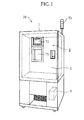
- FIGS. 1 and 2 show a thermostat-humidistat container 1 (chamber) as an environmental tester 10 according to an embodiment of the present invention.
- the thermostat-humidistat container 1 is used for stability tests of pharmaceuticals, for example. For this reason, temperature and humidity in a test chamber S are stably kept within the predetermined ranges, respectively.
- the thermostat-humidistat container 1 has a contour in the shape of a substantially rectangular parallelepiped, and a door 2 extending from an upper end to a center section of a front face of the thermostat-humidistat container 1 is attached to the thermostat-humidistat container 1 to be able to open and close.
- a consol panel 71 for, for example, setting target values for controlling temperature and humidity and a display 72 for displaying the set values, and the like are disposed to be aligned in the vertical direction on a front face of the door 2.
- the door 2 of the thermostat-humidistat container 1 is opened to access to the test chamber S which is in the shape of a substantially rectangular parallelepiped and is formed in the thermostat-humidistat container 1, so that a specimen can be placed in the test chamber S, or a specimen placed in the test chamber can be taken out.
- An air outlet 3 is formed in an upper portion of a wall surface at the depth of the test chamber S, and through the air outlet 3, conditioned air of adjusted temperature and humidity is discharged to the test chamber S from an air conditioner 8 (see FIG. 3 ) including a refrigerator, a humidifier, a heater, etc.
- thermostat-humidistat container 1 An air inlet is formed in a lower portion of the wall surface at the depth of the test chamber S, and air in the test chamber S is sucked through the air inlet and is then supplied to the air conditioner 8.
- air in the thermostat-humidistat container 1 air is circulated between the test chamber S and the air conditioner 8, thereby stably keeping the temperature and the humidity in the test chamber S within the predetermined ranges, respectively.
- the thermostat-humidistat container 1 defines a closed space between the test chamber S and the air conditioner 8.
- two shelf boards 4 are arranged to be aligned in the vertical direction, and specimens are placed on the shelf boards 4.
- the number and the position of the shelf board 4 are suitably determined.
- the nine additional sensors 5 are arranged respectively on a ceiling surface, and on a bottom surface of the test chamber S to have intervals therebetween, and a single additional sensor 5 is arranged at the center of the test chamber S (at the center of the shelf board 4 in the illustrated example).
- the nine additional sensors 5 in total are sensors for measuring the temperature and the humidity at the respective positions in the test chamber S to determining the temperature and humidity distribution in the thermostat-humidistat container.
- the number of the additional sensors 5 is not limited to nine, and the configuration shown in FIG. 2 is merely an example.
- the arrangement positions of the additional sensors 5 can suitably be determined depending on the number of the additional sensors 5.
- the additional sensors 5 are preferably placed substantially uniformly in the test chamber S to obtain the distributions of the temperature and the humidity in the test chamber S.
- the additional sensors 5 are preferably placed at nine positions in total, i.e., at eight corners and the center of the test chamber S.
- the positions of the additional sensors 5 are not limited to the above nine positions.
- the additional sensor 5 is arranged at at least one position away from an existing first temperature and humidity sensor 9 described below, the temperature and humidity distribution efficiency in the thermostat-humidistat container is improved compared to that in a configuration to which a control unit 65 of the present embodiment is not added.
- the thermostat-humidistat container 1 includes a single first temperature and humidity sensor 9 arranged at the air outlet 3, and based on values measured by the first temperature and humidity sensor 9, the temperature, the relative humidity, and the absolute humidity of air discharged through the air outlet 3 are determined.
- the arrangement position of the first temperature and humidity sensor 9 is not limited to the position near the air outlet 3, but the first temperature and humidity sensor 9 may be arranged near the air inlet.
- Measured signals from the first temperature and humidity sensor 9 is sent to a controller 6 disposed in a lower portion of the thermostat-humidistat container 1.
- the controller 6 controls the air conditioner 8 based on values measured by the sensors 5 and 9 in such a manner that the temperature and the humidity in the test chamber S are the predetermined temperature and humidity, respectively.
- measured signals from the additional sensors 5 are sent to an additional unit 60.
- These plurality of additional sensors 5 and the additional unit 60 form the control unit 65 according to the present embodiment.
- the controller 6 includes a receiver 6f configured to receive a signal from the first temperature and humidity sensor 9, and a data memory 6a configured to store the signal received by the receiver 6f.
- the controller 6 further includes a temperature and humidity setter 6b for setting target values for controlling the temperature and the humidity in the test chamber S based on signals from the consol panel 71 through which an operator sets the target temperature and humidity, and an operating section 6d which receives signals from the temperature and humidity setter 6b and the data memory 6a, and carries out various operations for controlling the air conditioner 8 as described below. Where necessary, the results of the operations are shown on the display 72 provided on the door 2 of the thermostat-humidistat chamber 1.
- the operating section 6d in the controller 6 computes the differences of the values of the temperature and the humidity measured by the first temperature and humidity sensor 9 from the set values, thereby generating a first correction value.
- the differences of the values measured by the first temperature and humidity sensor 9 from the set values are determined in a determination section 6e. Based on the determination results, a signal 73 and an alarm 74 which give an operating section a warning are operated.
- the differences of the values of the temperature and the humidity measured by the first temperature and humidity sensor 9 from the set values are computed based on measured data from the first temperature and humidity sensor 9 and the plurality of additional sensors 5, and are generated as second correction values by the additional unit 60.
- the controller 6 further includes a control adjustment operating section 6c which carries out an operation for control adjustments of the air conditioner 8. Based on the determination results of the determination section 6e and the second correction values generated by the additional unit 60, the control adjustment operating section 6c controls the air conditioner 8.
- the controller 6 further includes an I/O section 6g for communication with the additional unit 60.
- the additional unit 60 includes, as illustrated in FIG. 4 , receivers 60a configured to receive signals from the additional sensors 5, and a data memory 60b configured to store the signals received by the receivers 60a, the set values for the temperature and the humidity from the controller 6, and the values measured by the first temperature and humidity sensor 9.
- the additional unit 60 further includes an operating section 60c configured to calculate the temperature and humidity distribution in the thermostat-humidistat container by an operation from the values measured by the first temperature and humidity sensor 9 and the values measured by the plurality of additional sensors 5, the values being stored in the data memory 60b.
- the results of the operation of the operating section 60c are sent to the controller 6 via an I/O section 60d.
- the door 2 of the thermostat-humidistat container 1 is opened to place a test specimen of the environmental test on the shelf board 4 disposed in the test chamber S.
- Target values are input via the consol panel 71 disposed on the front face of the door 2. Here, an operator can see the target values displayed on the display 72 to check whether or not the operation is correct.
- conditioned air of adjusted temperature and humidity is discharged to the test chamber S by the air conditioner 8 through the air outlet 3.
- Air is supplied to the air conditioner 8 through the air inlet disposed in the lower portion of the wall surface at the depth in the test chamber S.
- the environmental tester 10 is operated such that while the air is circulated in this way between the test chamber S and the air conditioner 8, the conditioned air whose temperature and humidity has been adjusted in the air conditioner 8 is supplied to the test chamber S in such a manner that the temperature and the humidity in the test chamber S are the input target values.
- the set values for the temperature and the humidity input via the consol panel 71 are sent from the data memory 6a of the controller 6 via the I/O section 6g to the additional unit 60, for example, at the timing of the input of the set values.
- temperature and humidity data signals measured by the first temperature and humidity sensor 9 disposed near the air outlet 3 in the test chamber S are stored in the data memory 6a via the receiver 6f of the controller 6. Timing at which the data signals are stored in the data memory 6a occurs in a predetermined cycle. Concurrently with storing the data signals measured by the first temperature and humidity sensor 9 in the data memory 6a, the data signals measured by the first temperature and humidity sensor 9 are sent from the data memory 6a via the I/O section 6g to the additional unit 60.
- temperature and humidity data signals measured by each of the nine additional sensors 5 substantially uniformly disposed in the test chamber S are stored in the data memory 60b via the receivers 60a of the additional unit 60.
- Timing at which the storing the temperature and humidity data signals are stored in the data memory 60b occurs preferably in the same cycle as that of the controller 6.
- the timing of sampling of the controller 6 and the timing of sampling of the additional unit 60 are not necessarily synchronous with each other.
- the operating section 60c computes the deviations of data signals from the additional sensors 5 stored in the data memory 60b from the data signals from the first temperature and humidity sensor 9 stored in the data memory 60b. In this case, a median or an average value of the data signals from the additional sensors 5 may be used in place of data signals from the additional sensors 5.
- the second correction values computed by the operating section 60c are sent to the controller 6 via the I/O section 60d.
- the second correction values sent from the additional unit 60 are stored in a predetermined region of the data memory 6a in the controller 6.
- the temperature and humidity setter 6b, the operating section 6d, the determination section 6e, and the control adjustment operating section 6c perform existing processes based on the second correction values stored in the predetermined region of the data memory 6a, so that it is possible to improve the temperature and humidity distribution efficiency.
- the results (the second correction values, etc.) of the operation of the additional unit 60 can be displayed on the display 72 as needed.
- the existing controller 6 has an external communication function such as the I/O section 6g. However, when the existing controller 6 does not have the external communication function, the external communication function has to be provided to the controller 6.
- the controller 6 has to update a control program (software) so as to be able to perform the process of storing the correction value computed by the additional unit 60 in the predetermined region of the data memory 6a, the process of reading the correction value from the predetermined region, etc.
- the existing controller 6 of the environmental tester 10 is used for controlling the temperature and the humidity
- the control unit 65 according to the present invention that is, the plurality of additional sensors 5 and the additional unit 60 is added by so-called retrofitting, so that it is possible to improve the temperature and humidity distribution efficiency in the thermostat-humidistat container.
- control unit 65 Since the control function of the existing controller 6 itself is used as it is, the control unit 65 according to the present embodiment can be added to the existing environmental tester 10 even when the manufacturer of the control unit 65 is different from the manufacturer of the environmental tester 10 to which the control unit 65 is added.
- the embodiment may have the following configuration.
- the thermostat-humidistat container 11 includes the test chamber S provided therein.
- the size of the test chamber S is not particularly limited. That is, a configuration in which a thermostat-humidistat room includes a test chamber S as a room having a size allowing the entrance of workers is also within the scope of the invention.
- the present invention can be utilized in environmental testers including thermostat-humidistat containers, and is also widely applicable to domestic and industrial air conditioners.
Landscapes
- Engineering & Computer Science (AREA)
- Physics & Mathematics (AREA)
- General Physics & Mathematics (AREA)
- Life Sciences & Earth Sciences (AREA)
- Chemical & Material Sciences (AREA)
- Automation & Control Theory (AREA)
- Immunology (AREA)
- Pathology (AREA)
- Analytical Chemistry (AREA)
- Biochemistry (AREA)
- General Health & Medical Sciences (AREA)
- Environmental & Geological Engineering (AREA)
- Environmental Sciences (AREA)
- Ecology (AREA)
- Health & Medical Sciences (AREA)
- Biodiversity & Conservation Biology (AREA)
- Combustion & Propulsion (AREA)
- Mechanical Engineering (AREA)
- General Engineering & Computer Science (AREA)
- Testing Resistance To Weather, Investigating Materials By Mechanical Methods (AREA)
- Air Conditioning Control Device (AREA)
Applications Claiming Priority (2)
| Application Number | Priority Date | Filing Date | Title |
|---|---|---|---|
| JP2012022020A JP5884124B2 (ja) | 2012-02-03 | 2012-02-03 | コントロールユニット |
| PCT/JP2012/007989 WO2013114505A1 (ja) | 2012-02-03 | 2012-12-13 | コントロールユニット |
Publications (2)
| Publication Number | Publication Date |
|---|---|
| EP2811284A1 true EP2811284A1 (de) | 2014-12-10 |
| EP2811284A4 EP2811284A4 (de) | 2015-09-09 |
Family
ID=48904594
Family Applications (1)
| Application Number | Title | Priority Date | Filing Date |
|---|---|---|---|
| EP12867089.0A Withdrawn EP2811284A4 (de) | 2012-02-03 | 2012-12-13 | Steuereinheit |
Country Status (5)
| Country | Link |
|---|---|
| US (1) | US9791869B2 (de) |
| EP (1) | EP2811284A4 (de) |
| JP (1) | JP5884124B2 (de) |
| CN (1) | CN104081183B (de) |
| WO (1) | WO2013114505A1 (de) |
Cited By (2)
| Publication number | Priority date | Publication date | Assignee | Title |
|---|---|---|---|---|
| CN109569746A (zh) * | 2018-12-31 | 2019-04-05 | 盐城蓝天试验设备有限公司 | 一种换气式霉菌试验箱 |
| IT201800001822A1 (it) * | 2018-01-25 | 2019-07-25 | Mitsubishi Electric Hydronics & It Cooling Systems S P A | Sala test per impianti |
Families Citing this family (6)
| Publication number | Priority date | Publication date | Assignee | Title |
|---|---|---|---|---|
| CN105158147B (zh) * | 2015-07-22 | 2018-03-13 | 深圳供电局有限公司 | 一种用于测试密封圈材料老化的装置及方法 |
| GB2544331B (en) * | 2015-11-13 | 2018-07-18 | Relequa Analytical Systems Ltd | An improved equilibrium relative humidity testing device and method |
| CN105510212A (zh) * | 2015-12-07 | 2016-04-20 | 芜湖凯尔电气科技有限公司 | 一种锂电池盐雾测试箱 |
| JP7079955B2 (ja) * | 2017-12-29 | 2022-06-03 | ナガノサイエンス株式会社 | 温度特性評価方法 |
| JP6941577B2 (ja) * | 2018-03-26 | 2021-09-29 | エスペック株式会社 | 環境形成装置 |
| WO2022181658A1 (ja) * | 2021-02-26 | 2022-09-01 | パナソニックIpマネジメント株式会社 | 空調システム |
Family Cites Families (10)
| Publication number | Priority date | Publication date | Assignee | Title |
|---|---|---|---|---|
| US20020168293A1 (en) * | 2001-03-22 | 2002-11-14 | Sensor Research And Development Corporation | Chemical protective materials testing system |
| JP2002364883A (ja) * | 2001-06-07 | 2002-12-18 | Hitachi Ltd | 多機能温湿度調節器 |
| US7173538B2 (en) * | 2004-06-25 | 2007-02-06 | Rm2, Inc. | Apparatus, system and method for monitoring a drying procedure |
| BRPI0621619A2 (pt) * | 2006-05-22 | 2011-12-13 | Airbus Deutschaland Gmbh | cámara climática e método de controle da mesma |
| JP2008232540A (ja) * | 2007-03-20 | 2008-10-02 | Toshiba Corp | 空調制御システム |
| US8276829B2 (en) * | 2007-11-30 | 2012-10-02 | Honeywell International Inc. | Building control system with remote control unit and methods of operation |
| JP2010107218A (ja) * | 2008-10-28 | 2010-05-13 | Nagano Science Kk | 湿度分布の測定方法、測定装置及び環境試験装置 |
| JP4972069B2 (ja) * | 2008-10-28 | 2012-07-11 | ナガノサイエンス株式会社 | 空調装置の制御方法、空調装置及び環境試験装置 |
| JP5327797B2 (ja) * | 2009-03-10 | 2013-10-30 | エスペック株式会社 | 恒温恒湿器 |
| CN102095679B (zh) * | 2010-12-31 | 2013-01-09 | 高铁检测仪器(东莞)有限公司 | 耐臭氧测试机 |
-
2012
- 2012-02-03 JP JP2012022020A patent/JP5884124B2/ja not_active Expired - Fee Related
- 2012-12-13 WO PCT/JP2012/007989 patent/WO2013114505A1/ja not_active Ceased
- 2012-12-13 CN CN201280068796.3A patent/CN104081183B/zh not_active Expired - Fee Related
- 2012-12-13 EP EP12867089.0A patent/EP2811284A4/de not_active Withdrawn
-
2014
- 2014-07-30 US US14/446,835 patent/US9791869B2/en not_active Expired - Fee Related
Cited By (2)
| Publication number | Priority date | Publication date | Assignee | Title |
|---|---|---|---|---|
| IT201800001822A1 (it) * | 2018-01-25 | 2019-07-25 | Mitsubishi Electric Hydronics & It Cooling Systems S P A | Sala test per impianti |
| CN109569746A (zh) * | 2018-12-31 | 2019-04-05 | 盐城蓝天试验设备有限公司 | 一种换气式霉菌试验箱 |
Also Published As
| Publication number | Publication date |
|---|---|
| US9791869B2 (en) | 2017-10-17 |
| JP5884124B2 (ja) | 2016-03-15 |
| CN104081183A (zh) | 2014-10-01 |
| CN104081183B (zh) | 2017-02-22 |
| EP2811284A4 (de) | 2015-09-09 |
| WO2013114505A1 (ja) | 2013-08-08 |
| JP2013160606A (ja) | 2013-08-19 |
| US20140339317A1 (en) | 2014-11-20 |
Similar Documents
| Publication | Publication Date | Title |
|---|---|---|
| US9791869B2 (en) | Environmental chamber control unit | |
| US9429535B2 (en) | Humidity determining device and environmental tester including the same | |
| US9151511B2 (en) | Method for controlling air conditioner and environmental tester | |
| US20140341253A1 (en) | Anomaly detector and environmental tester including the same | |
| CN107062557A (zh) | 一种空调扫风自动调节方法及其装置、一种空调 | |
| US20160252331A1 (en) | System, device, and method for detection of projectile target impact | |
| JP2010107218A (ja) | 湿度分布の測定方法、測定装置及び環境試験装置 | |
| WO2021013195A1 (en) | Lighting system for a household appliance | |
| CN109813045A (zh) | 搁架高度调节方法、储物容器、及可读存储介质 | |
| US11906175B2 (en) | Orientation-based HVAC control | |
| EP3026359B1 (de) | Klimaanlage | |
| US20200292374A1 (en) | Method for the verification of pipettes | |
| US20040009102A1 (en) | Safety cabinet with safety monitoring system | |
| CN116149398B (zh) | 一种基于数据反馈的温度控制器精确控制系统及方法 | |
| EP4092401B1 (de) | Feuchtigkeitsmessgerät, zustandsdiagnoseverfahren für feuchtigkeitsmessgerät und programm | |
| KR20110096977A (ko) | 냉장고 검사용 장치 | |
| CN104931156A (zh) | 双金属温度计校验装置 | |
| CN204718712U (zh) | 双金属温度计校验装置 | |
| CN115371347B (zh) | 冰箱储物间室使用状态的检测方法、检测系统和冰箱 | |
| KR19990002831A (ko) | 냉장고의 고내온도 표시방법 | |
| US20160084699A1 (en) | Food item scales, methods for calibrating same, and methods for determining the weight of food items | |
| JP2010175343A (ja) | 温度校正装置 | |
| GB2528347A (en) | Highly accurate temperature measurement system | |
| KR20090008883A (ko) | 실린더 동작 시간 설정 방법 및 실린더 동작 시간 설정시스템 |
Legal Events
| Date | Code | Title | Description |
|---|---|---|---|
| PUAI | Public reference made under article 153(3) epc to a published international application that has entered the european phase |
Free format text: ORIGINAL CODE: 0009012 |
|
| 17P | Request for examination filed |
Effective date: 20140801 |
|
| AK | Designated contracting states |
Kind code of ref document: A1 Designated state(s): AL AT BE BG CH CY CZ DE DK EE ES FI FR GB GR HR HU IE IS IT LI LT LU LV MC MK MT NL NO PL PT RO RS SE SI SK SM TR |
|
| AX | Request for extension of the european patent |
Extension state: BA ME |
|
| DAX | Request for extension of the european patent (deleted) | ||
| RA4 | Supplementary search report drawn up and despatched (corrected) |
Effective date: 20150810 |
|
| RIC1 | Information provided on ipc code assigned before grant |
Ipc: G01N 17/00 20060101AFI20150804BHEP |
|
| 17Q | First examination report despatched |
Effective date: 20161221 |
|
| RIC1 | Information provided on ipc code assigned before grant |
Ipc: G01N 33/15 20060101ALN20170830BHEP Ipc: G01N 17/00 20060101AFI20170830BHEP |
|
| GRAP | Despatch of communication of intention to grant a patent |
Free format text: ORIGINAL CODE: EPIDOSNIGR1 |
|
| INTG | Intention to grant announced |
Effective date: 20171011 |
|
| STAA | Information on the status of an ep patent application or granted ep patent |
Free format text: STATUS: THE APPLICATION IS DEEMED TO BE WITHDRAWN |
|
| 18D | Application deemed to be withdrawn |
Effective date: 20180222 |