EP2809942B1 - Vorrichtung und/oder leitung zur erkennung des einem verbrennungsmotor zugeführten brennstoffs - Google Patents
Vorrichtung und/oder leitung zur erkennung des einem verbrennungsmotor zugeführten brennstoffs Download PDFInfo
- Publication number
- EP2809942B1 EP2809942B1 EP13712353.5A EP13712353A EP2809942B1 EP 2809942 B1 EP2809942 B1 EP 2809942B1 EP 13712353 A EP13712353 A EP 13712353A EP 2809942 B1 EP2809942 B1 EP 2809942B1
- Authority
- EP
- European Patent Office
- Prior art keywords
- duct
- fuel
- fitting
- sensor
- coupling
- Prior art date
- Legal status (The legal status is an assumption and is not a legal conclusion. Google has not performed a legal analysis and makes no representation as to the accuracy of the status listed.)
- Active
Links
Images









Classifications
-
- F—MECHANICAL ENGINEERING; LIGHTING; HEATING; WEAPONS; BLASTING
- F02—COMBUSTION ENGINES; HOT-GAS OR COMBUSTION-PRODUCT ENGINE PLANTS
- F02M—SUPPLYING COMBUSTION ENGINES IN GENERAL WITH COMBUSTIBLE MIXTURES OR CONSTITUENTS THEREOF
- F02M55/00—Fuel-injection apparatus characterised by their fuel conduits or their venting means; Arrangements of conduits between fuel tank and pump F02M37/00
- F02M55/02—Conduits between injection pumps and injectors, e.g. conduits between pump and common-rail or conduits between common-rail and injectors
- F02M55/025—Common rails
-
- F—MECHANICAL ENGINEERING; LIGHTING; HEATING; WEAPONS; BLASTING
- F02—COMBUSTION ENGINES; HOT-GAS OR COMBUSTION-PRODUCT ENGINE PLANTS
- F02M—SUPPLYING COMBUSTION ENGINES IN GENERAL WITH COMBUSTIBLE MIXTURES OR CONSTITUENTS THEREOF
- F02M69/00—Low-pressure fuel-injection apparatus ; Apparatus with both continuous and intermittent injection; Apparatus injecting different types of fuel
- F02M69/46—Details, component parts or accessories not provided for in, or of interest apart from, the apparatus covered by groups F02M69/02 - F02M69/44
- F02M69/462—Arrangement of fuel conduits, e.g. with valves for maintaining pressure in the pipes after the engine being shut-down
- F02M69/465—Arrangement of fuel conduits, e.g. with valves for maintaining pressure in the pipes after the engine being shut-down of fuel rails
-
- F—MECHANICAL ENGINEERING; LIGHTING; HEATING; WEAPONS; BLASTING
- F02—COMBUSTION ENGINES; HOT-GAS OR COMBUSTION-PRODUCT ENGINE PLANTS
- F02M—SUPPLYING COMBUSTION ENGINES IN GENERAL WITH COMBUSTIBLE MIXTURES OR CONSTITUENTS THEREOF
- F02M2200/00—Details of fuel-injection apparatus, not otherwise provided for
- F02M2200/24—Fuel-injection apparatus with sensors
Definitions
- the present invention generally relates to a device for detecting characteristics of a liquid, such as the type of at least one liquid and/or the mixing percentage of different fluids and/or the presence and/or concentration of some elements in a fluid, such as a liquid fuel fed to internal combustion engines, e.g. petrol, diesel fuel, ethanol, etc.
- a detection device equipped with suitable means, in particular of the hydraulic and/or mechanical type, for connecting or fitting it to a duct for a combustible liquid or fuel, in particular a duct associated or associable with valves or injectors of internal combustion engines, such as a so-called "fuel rail".
- the connecting or fitting means allow removal of the device, e.g. for maintenance or replacement of the device or of the associated duct.
- Another strongly felt need is detecting the quality of the fuel, which may have such a concentration of impurities or other compounds, especially water, which may give rise to engine operation problems, or may contain mixtures of different fuels.
- the difference in density between the different fuels, or between the latter and any water possibly contained therein may cause false readings due to stratification of liquids having a different density.
- the senor will detect the concentration of the liquid layer in which it is immersed, without however taking into account any other liquids forming different (higher or lower) layers.
- the sensors in the fuel circuit of the combustion engine, i.e. downstream of the tank; some examples of possible arrangements of the sensors are described in German patent application DE 103 09 720 , wherein the sensor is built in the injector of a diesel engine, or along a fuel rail, as disclosed, for example, in United States patent US 6,885,199 .
- the solution wherein the sensor is associated with an injector may be difficult to implement in multi-cylinder engines, e.g. with four or more cylinders, or with a plurality of sensors.
- each sensor will provide indications about the fuel being injected into the respective cylinder, and therefore the engine control system (typically an electronic control unit) will have to process readings which may be different from one another.
- the engine control system typically an electronic control unit
- the sensor built in the injector must necessarily be small, and this may cause the sensor to become difficult and expeansive to manufacture.
- sensors having different configurations have different transfer functions as well, and therefore dedicated systems (instruments, software, etc.) are required for their control, from case to case, resulting in higher costs.
- the present invention aims at overcoming the above-mentioned drawbacks of prior-art sensors.
- the technical problem underlying the invention is to provide a device for detecting the characteristics of a liquid, in particular, but not limited to, a fuel or mixtures thereof for internal combustion engines, which allows reliable detecting in a simple manner, i.e. substantially without altering the way in which the fuel is fed to the engine.
- a further problem is to provide a device for detecting the characteristics of a liquid, in particular, without being limited to, a fuel or mixtures thereof for internal combustion engines, which can be comprised in systems equipped with fuel heaters, in particular heaters associated with the fuel rail.
- the idea for solving the above-mentioned problem is to detect the characteristics of the fuel flowing in the "fuel rail” or “common rail” at a point external thereto, preferably in the proximity of said "fuel rail” or “common rail”.
- the fuel is substantially at the same pressure level as the "fuel rail” or “common rail”, which may range from a few bars for flexible engines (e.g. 1.5-3.5 bar) to many hundreds of bars for diesel engines.
- the detection of the characteristics of the fuel flowing in the fuel rail is independent of the number of cylinders: in practice, the sensor in use does not need to be changed for each application having a different number of cylinders.
- the fuel in the duct has stable and uniform pressure characteristics, thereby ensuring accurate and reliable detections.
- Pressure variations in the liquid may be due to a lower fuel level in the tank or to the opening of the engine valves: a pressure higher than the atmospheric one makes the variations less relevant in percentage terms.
- the invention also relates to a fuel duct which can be associated with a sensor according to the invention or a fuel duct of the "fuel rail” or “common rail” type, having the features set out in the appended claims.
- a device according to the invention is designated as a whole D and comprises one or more sensors 1, also referred to as sensor means, which sensor is at least partly lapped, in an operating condition, by a fluid flowing in a fuel supply duct 2 for an internal combustion engine.
- the duct 2 is of the "fuel rail” type, i.e. a duct comprising a fuel inlet 3a, which in the example of Figs. 4,5 is located at one end 2a, and a plurality of outlets 4, which lead to the injectors (not shown in the drawings) of an internal combustion engine of the flexible type running on different fuels, such as petrol and ethanol, or the like.
- fuel rail i.e. a duct comprising a fuel inlet 3a, which in the example of Figs. 4,5 is located at one end 2a, and a plurality of outlets 4, which lead to the injectors (not shown in the drawings) of an internal combustion engine of the flexible type running on different fuels, such as petrol and ethanol, or the like.
- the dry part of the sensor 1 comprises a housing 5 for the circuit components, which is closed by a cover 6; the external part of the sensor is also connected to the electric power supply and to the engine management network of the motor vehicle in which the device has been installed, by means of a tripolar electric connector 7.
- the housing 5 of the sensor 1 has such a shape as to contain at least one detection and/or control circuit, such as an electronic board 9, which performs at least the function of processing the signals derived or transmitted from the sensing element 14 through terminals 12,13 to which it is connected, and then sending the detected data as electric signals to one or more of the terminals 11 of the connector 7; in this example, said electric signals are generated by deformation of a so-called piezoelectric bender 14 (see Figs. 26 and 27 ).
- Said housing 5 associated with the sensor 1 is preferably adapted to contain also an insulating element 10, in particular a material suitable for enclosing or at least partly coating said electronic board 9, such as a polymer or a resin, e.g. poured into the housing and/or onto the circuit or board 9 and then cured or hardened; said insulating element being in particular adapted to protect said circuit or board 9 against external agents or contaminants.
- an insulating element 10 in particular a material suitable for enclosing or at least partly coating said electronic board 9, such as a polymer or a resin, e.g. poured into the housing and/or onto the circuit or board 9 and then cured or hardened; said insulating element being in particular adapted to protect said circuit or board 9 against external agents or contaminants.
- the senor comprises an element 14 adapted to vibrate when appropriately energized, such as a lamina associated with a piezoelectric layer (also called “bender"), which is caused to vibrate by means of electric signals at preset frequencies, so as to be able to detect properties of the fuel, such as viscosity, density or the like, e.g. by detecting the vibration variations induced by the fluid or fuel with which the lamina or bender comes in contact.
- a piezoelectric layer also called “bender”
- the piezoelectric bender 14 For detection, the piezoelectric bender 14 must be immersed in and/or lapped by the liquid fuel and energized by an alternating voltage that causes it to vibrate at a certain resonance frequency.
- a circuit and/or board 9 associated with the bender 14, in particular adapted to control the resonance frequency of the latter, is shown in Fig. 28 .
- the piezoelectric bender 14 comprises one or more thickness-polarized piezoelectric layers 14a and 14b, separated by a dielectric, constrained to each other and integral at one end with the housing 5 through holes 111 compatible with fastening means (not shown in the drawings) comprised in said housing 5; this assembly, when electrically powered, produces a flexural deformation.
- the terminals 12 and 13 are respectively associated with the two opposite surfaces of the piezoelectric bender 14, by welding or the like.
- the inner (wet) part of the sensor also comprises, in addition to the piezoelectric bender 14, which is inserted and held in position by an aperture 15 in front of the housing 5, a groove 16a around the aperture 15.
- the groove houses a sealing gasket 16, which prevents the liquid present in the duct 2, e.g. petrol or ethanol, from leaking out.
- the sensor comprises two terminals 12 and 13, consisting of filiform conductors obtained by means of cylindrical bars made of copper or another suitable electrically conductive material, and having curved free ends 12b, 13b; in the operating condition of the sensor, these curved ends 12b,13b are directly in contact with the piezoelectric bender 14.
- the base ends 12a, 13a of the internal terminals 12,13 are plugged into suitable seats 21 on the board 9.
- the seats 21 are also used as clamps to provide electric contact between the terminals 12,13 and the circuit associated with the board 9; therefore, in order to ensure a proper contact, on the base ends 12a, 13a there are, in this example, insulating rings 19 and anti-removal rings 20.
- the piezoelectric layers 14a,14b of the bender 14 are connected to the control circuit 9 by means of the terminals 12 and 13.
- the output voltage of the bender 14, or the resonance frequency thereof, is controlled in order to detect changes in the viscosity of the fluid.
- the viscosity of the fluid can be determined as a function of the damping of the bender's vibrations, or of the variation in the bender's vibration frequency, or, more in general, of the bender's frequency response.
- Fig. 26 With reference to the diagram shown in Fig. 26 , there is shown that it is possible to apply a voltage across the bender by means of the terminals 12 and 13, with amplitude and frequency optimized for causing it to vibrate.
- the bender's structure is subjected to flexure cycles depending on the supply voltage, which will preferably be the fundamental resonance one.
- Said structure and/or frequency can be optimized according to the type of fluid to be measured.
- the diagram of Figure 26 shows an electronic layout comprising an actuation stage 103 of the bender 14 and a detection stage 101,102,103 of the bender 14, which together can also constitute a feedback loop 100 to conveniently cause the bender to oscillate at its resonance frequency; said detection stage and/or feedback loop 100 comprises an alternating voltage meter 101, an analog/digital converter 102 and a microcontroller 103.
- the alternating voltage meter 101 is used for monitoring the bender's output signal and outputting a datum which will be proportional to the frequency and amplitude of the detected voltage.
- This data stream is then sent to the microcontroller 103, which can process it by using appropriate computation algorithms and/or on the basis of predefined data tables, and/or can transform it, e.g. by linearizing it.
- the phase of the feedback signal can preferably be advanced (or retarded) by approximately 90°.
- This function is carried out by the microprocessor 103 based on the reading taken by the alternating voltage meter 101.
- the microcontroller closes the feedback loop 100 by appropriately controlling the bender energization signal in such a way as to maintain the optimal resonance, and, based on the received measurements, it can determine the viscosity of the fluid.
- the resonance frequency depends on the bender's physical dimensions and on the materials it is made of: for specific automotive applications, it will likely be necessary to operate at higher frequencies than the typical ones generated by the vehicle: it may therefore be particularly recommended to manufacture, by using MEMS techniques, a miniaturized bending element operating at high frequencies.
- a MEMS bender may be made of silicon or alumina, and the conductive and piezoelectric elements may be manufactured by silk-screening or by using typical microelectrics techniques such as thermal evaporation, sputtering and CVD for the active layers.
- a piezoelectric element associated with a piezoresistive element wherein the piezoelectric element is used for forcing the vibration, and said piezoresistive element is used as a sensing element for measuring the amplitude and phase of the vibration.
- Said piezoresistive element may be of the silk-screened or deposited type; for example, it may be made by depositing piezoresistive ink onto a suitable insulating or insulated substrate or support.
- the bender's installation considerably affects its viscosity reading sensitivity, which can be significantly increased by creating suitable constraints in the form of fixed walls placed at an appropriate distance from the vibrating element.
- the propagation of the waves generated by the shearing stress which in turn depend on the viscosity of the medium, is extremely limited: the bender's damping variation can thus only be measured if the bender is suitably housed within a container designed to keep a small distance between the fixed parts and the vibrating ones.
- MEMS technologies it is possible to manufacture both the vibrating elements and the fixed elements as one piece, with micrometric tolerances and at low cost.
- the output voltage or the resonance frequency are monitored in order to determine viscosity changes.
- the electric signal obtained by applying an alternating potential difference to the terminals 12,13, and hence to the piezoelectric bender 14 or to any other sensing elements, allows to obtain an indication about the characteristics of the liquid fuel in the duct 2.
- variable percentages in petrol e.g. antiknocking additives, solvents, etc.
- water in ethanol will bring about changes in the physical properties of the liquid, such as viscosity, density, velocity, etc.
- the properties of the liquid that can be detected through the present invention may however differ according to the type of sensor in use, which must not necessarily be a piezoelectric bender; therefore, the detections carried out may be electric (inductive, resistive, capacitive, etc.), acoustic, optical or even combinations of one or more of these variants, or any other sensor suitable for this purpose.
- the sensor can detect such changes in the physical properties of the liquid, preferably as a function of a variation in the electric voltage and/or current circulating in the circuit associated with the board 9, which, when appropriately processed, can provide an indication about the composition and/or other characteristics of the fuel.
- the main embodiment of the device D according to the invention comprises a fitting or body 52 of the sensor 1 described so far.
- the use of the duct 52 also allows to advantageously move the sensor 1 farther from the engine (not shown in the drawings) or from any other heat source, so as to improve the stability of the readings.
- some parts of the sensor 1 and/or of the device D may be advantageously adapted to dissipate heat, i.e. they may be made of a thermally conductive material, such as a suitable metal or polymer or thermoplastic material, e.g.
- said parts of the sensor 1 may, for example, be the housing 5 and/or the body or fitting 52 and/or hydraulic connecting means attached to the fuel duct 2 and/or mechanical fastening and/or supporting means attached to the fuel duct 2, as will be further described below.
- the device shown therein which is not part of the invention, comprises the hydraulic fitting or body 52 having a plurality of apertures or seats or ways, wherein an inlet 53 is connected to a fuel supply duct or to the delivery side of a fuel supply pump (not shown in the drawings) by means of a coupling 54; the fitting 52 also comprises a seat 50 having an aperture that houses the sensor 1, and an outlet 52b that communicates downstream with a fuel duct 2 of the fuel rail type.
- the inlet coupling 54 may be integrated with the fitting 52, e.g. co-moulded or moulded with the plastic fitting.
- the fuel which in flexible combustion engines is at a pressure higher than 2.5 bar, or of several hundreds of bars in diesel engines, flows into the fitting 52 and, after having gone through it, enters the duct 2; such fuel flow comes in contact with or laps the sensor 1 and/or said sensing element or bender 14, preferably axially to the sensor 1 or substantially parallel to said sensing element 14.
- the fitting 52 has a male thread 56 to be coupled to a threaded ring nut 57 associated or associable with the duct or "fuel rail" 2, and rotatably constrained to one end or head of an axially hollow adapter insert 58 (also referred to as fastening or supporting means), whose opposite end or threaded shank is coupled to or engaged into a corresponding thread in the end of the duct 2 (visible in Figs. 5 and 6 ).
- the insert 56 may be integrated with the fitting 52, e.g. co-moulded or moulded with the plastic fitting.
- a slot 52a is also provided in a groove 17 of the housing 5 of the sensor 1, so that the latter is secured to the fitting 52 by the prongs of the clip 8 engaging one of the slots 17,52a; said fastening means 8 thus allow to secure and/or make integral with each other said body 52 and housing 5.
- the sensor 1 and/or the body 52 can thus be firmly mounted outside the duct or "fuel rail" 2, even in the presence of high pressures in the fuel duct, such as those required by injection or diesel engines.
- the hydraulic tightness of the system is ensured by a set of gaskets 59a, 59b, 59c adapted to prevent the pressurized fuel from leaking out.
- an O-ring gasket 15a similar to the gaskets located between the fitting 52 and the coupling 54, and/or interposed between the fittings 52 and 58, and/or interposed between the fuel rail 2 and the fitting 58.
- the senor 1 comprises a seat 15b capable of firmly receiving the gasket 15a; said seat 15b is located near the groove 17.
- a fuel flow enters through the inlet 53 of the fitting 52 and runs through the seat 50, thus lapping the bender 14 in a direction prevalently parallel to the axis of the latter. Said fuel flow finally reaches the duct 2, going through the outlet 52b and splitting among the outlets 4 prior to entering the engine (not shown in the drawings).
- the Figures 4, 5 , 6 represent solutions suited for application to one end of the fuel duct 2 of the "fuel rail” or “common rail” type.
- the device of the invention may be arranged in a radial position or adjacent to an intermediate or terminal region of the fuel duct 2.
- the senor In these conditions, the sensor must be firmly supported so as to be able to stand the great stresses resulting, for example, from vibrations transmitted by the engine and/or produced by the vehicle, or deriving from the pressures involved in the fuel supply system, as aforementioned.
- the senor must be supported without needing any changes to the environment where the fuel duct is arranged, i.e. the engine compartment, or to the components of the engine housed in the engine compartment.
- the senor is supported in connection with at least two points of the fuel duct, so as to obtain conditions of sufficient stability and rigidity to stand the stresses deriving from the high pressure of the fluid flowing therein, as well as the aforementioned vibrations and/or jolts of the vehicle.
- the duct 2 directly acts as a supporting element for the sensor 1 to which it is coupled, particularly at at least two distinct and/or spaced points, preferably in substantially opposed positions or with at least one point substantially located in a terminal position, possibly with at least one point located in a substantially intermediate position, with respect to the sensor and/or to the hydraulic fitting 62 thereof, so that the duct 2 and the sensor 1 will substantially behave as one rigid piece.
- the hydraulic connection between the sensor 1 and the duct 2 which will thus perform two functions, i.e. the hydraulic function and the function of supporting the sensor and/or the associated fitting.
- the sensor 1 and/or the three-way fitting associated therewith is supported in connection with two distinct points of the fuel duct 2, mechanically at one point and mechanically-hydraulically at the other point because, as aforesaid, the invention exploits the hydraulic connection between the sensor 1 and/or the associated three-way fitting.
- Figures 7 and 8 represent one possible embodiment of the invention incorporating these situations.
- the senor 1 is housed in a seat 60 of a body or fitting 62, analogous or similar to the body 52, 52' of the previously described embodiments, but said fitting 62 may be slightly longer and/or shaped differently.
- An inlet 63 of the fitting 62 is connected upstream to the delivery side of the fuel supply system and/or of the associated pump (not shown in the drawings) through an inlet tubular element or coupling 64; the fitting 62 is connected downstream to an outlet tubular element or coupling 80 associated with or connected to an inlet 3b of the fuel duct 2.
- the coupling 80 is secured to the inlet 3b and to the fitting 62. More specifically, the coupling 80 and the inlet 3b of the duct 2 are connected to each other by means of respective threaded couplings, such as a male threaded insert 83 surmounted by a nut 84 integral with said coupling 80; furthermore, said threaded insert 83 is positioned on one end of said coupling 80, and the nut 84 is coaxial to said threaded insert 83, so as to facilitate the connection of said coupling 80 to the inlet 3b, which is equipped with a respective female threaded coupling.
- respective threaded couplings such as a male threaded insert 83 surmounted by a nut 84 integral with said coupling 80; furthermore, said threaded insert 83 is positioned on one end of said coupling 80, and the nut 84 is coaxial to said threaded insert 83, so as to facilitate the connection of said coupling 80 to the inlet 3b, which is equipped with a respective female
- the coupling 70 comprises a circular structure 72 comprising a push-button 73 and integrating elastic elements, which structure engages with an annular element 85 comprised in the coupling 80.
- the coupling 70 also comprises a set of gaskets 71 ensuring a proper seal between the fitting 62 and the coupling 80 when fuel is flowing therein.
- the set of gaskets 71 comprises two rubber O-rings 71a, between which there is a metal O-ring 71b, the O-rings being positioned around a centering ring 71c; said centering ring comprises a central rib 71d that allows it to be positioned correctly, preventing said ring 71c from sliding inside the fitting 62.
- the coupling 70 is positioned; such positioning is made easier by the presence of a housing seat 68 at the outlet of the fitting 62, compatible with the coupling 70.
- This seat 68 allows pressing the push-button 73 also when the coupling 70 is in an operating condition. During assembly, this seat 68 can be elastically deformed in order to facilitate the positioning of the coupling 70 around the centering ring 71c.
- the fitting 62 is held in position by a bracket 86; said bracket 86 consists of two L-shaped portions 86a,86b, each of which comprises, respectively, a horizontal portion 86d,86e; said horizontal portions 86d, 86e slideably engage with a base guide 87 (also referred to as fastening or supporting means) associated with the fuel duct 2.
- the guide 87 comprises two opposite guides 87d,87e respectively compatible with the horizontal portions 86d,86e to provide a quick connection; said guides 87d,87e have a linear shape and are obtained in respective compatible reliefs 87a and 87b comprised in the guide 87.
- the senor 1 is supported, together with the fitting 62, at two points of the fuel duct 2, i.e. at the inlet 3b by the coupling 80 and at the reliefs 87 by the bracket 86.
- this result is attained by exploiting the hydraulic connection between the sensor 1 and the associated fitting 62, thanks to the coupling pipe 80 which, in addition to the normal hydraulic function, also performs the mechanical function, together with the bracket 86, of supporting the fitting 62 with the sensor 1.
- the 90-degree shape of the coupling pipe 80 represents an advantageous and effective feature, since its vertical portion de facto constitutes an upright supporting the horizontal portion of the coupling 80, which is connected at one end to the fitting 62.
- the latter is supported at the other end by the bracket 86, thus being rigidly secured to the fuel duct 2 so as to resist the stresses induced by the aforementioned vibrations of the engine or of the vehicle.
- the senor 1 is inserted into a fitting 62' having the same function as the fitting 62 of the previous embodiment; said fitting is held integral with the duct 2 by a bracket 86' having an S-like shape, so as to limit the space occupied inside an engine compartment (not shown in the drawings).
- the bracket 86' comprises a fastening eyelet 88 at its lower end, while at the opposite end it is coupled to the fitting 62' by welding, glueing or the like; said fastening eyelet 88 is compatible with a fastening hole 89 comprised in the duct 2, so that the duct 2 and the bracket 86' can be made integral with each other by means of a bolt or a similar fastening means (not shown in the drawings), thus securing the fitting 62' to the duct 2, possibly by simply changing the length of said bolt.
- Such a solution allows to use a bolt or a similar fastening means, typically already used for fastening the duct 2, also for fastening the bracket 86' of the fitting 62 and/or sensor 1.
- the bracket 86' preferably also comprises a positioning and/or anti-rotation element 141, located in the proximity of said fastening eyelet 88, which is coupled to a respective seat 142 located near the fastening hole 89 of the duct 2.
- Said positioning and/or anti-rotation element 141 and said seat 142 are substantially complementary to each other, i.e. they match precisely; in particular, this is useful in order to centre the hole of the eyelet 88 with the fastening hole 89, thus making said bolt easy to install, and/or in order to prevent any angular movement of the fitting 62 relative to the fuel duct 2, thus ensuring more solidity and a more secure locking of the parts, and also avoiding any anomalous stresses upon the fuel coupling.
- this variant utilizes a coupling 80 with suitable sealing means.
- the coupling 80 is positioned in a way opposite to the previously described variant, i.e. it is made integral with the fitting 62', thus requiring a female thread 65 at the exit of the fitting 62', to be coupled to a respective male thread of the coupling 80.
- the other end of the coupling 80 creates a quick connection by means of the annular fitting element 85, which connects to a quick coupling 81 provided on the inlet 3b' of the duct 2.
- the quick coupling 81 comprises two rubber O-rings 81a, a metal O-ring 81b between the two rubber O-rings 81a, and a centering ring 81c; the O-rings 81a,81b are positioned under the centering ring 81c, while a support ring 81d, compatible with the edge of the inlet 3b', is fitted into the top of it.
- That part of the quick coupling 81 which is external to the duct 3b' comprises a diameter reducer 81e compatible with the support ring 81d, a spacer 81f that fits into the diameter reducer 81e, and a hollow cylindrical support 81g compatible at the bottom with the spacer 81f and at the top with a snap connector 81h compatible with the coupling 80.
- the snap connector 81h comprises a push-button 81i which, when pressed, elastically modifies a constraint mechanism (not shown in the drawings) located within the snap connector 81h; said constraint mechanism engages with the annular element 85, thereby allowing the quick coupling 81 to be constrained to the coupling 80.
- a constraint mechanism (not shown in the drawings) located within the snap connector 81h; said constraint mechanism engages with the annular element 85, thereby allowing the quick coupling 81 to be constrained to the coupling 80.
- This solution allows mounting the sensor 1 - fitting 62' assembly with a substantially vertical movement, until the quick coupling 81 reaches its locking position, plus a slight lateral movement to cause said positioning and/or anti-rotation element 141 to engage with the respective seat 142 and the eyelet 88 to approach the hole 89; finally, installation can be completed by fastening together the bracket 86' and the duct 2 by using a bolt (not shown in the drawings) or the like, after having aligned the fastening eyelet 88 and the fastening hole 89.
- a fitting 62" similar to that of the previous variant is employed.
- the fitting 62" comprises a preferably corrugated end 66 that can be coupled to a tubular element 80', in particular made of elastomeric material, through the use of a cable tie 82, the latter being capable of providing a stable coupling between the two components, in particular by compression.
- tubular element 80' is coupled to an inlet 3b", also preferably corrugated like the end 66, thus making it possible to use another cable tie 82 in order to secure the connection between the coupling 80' and said inlet 3b"; said inlet 3b" is positioned at one end of the duct 2 and radially thereto.
- Said coupling 80' may conveniently be made of elastomeric or plastic material or the like, thus making mass production economically advantageous.
- the fitting 62" is held integral with the duct 2 by means of a bracket 86", which in this variant has a substantially straight shape and is coupled to the duct 2 in the same way as the bracket 86' already described, i.e. through the fastening eyelet 88 and the fastening hole 89, and possibly also through said positioning and/or anti-rotation means 141,142.
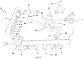
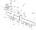
- Figures 15-17 show another variant of the invention, which differs from the previous one in the fastening means and in the positioning of an inlet 3b''' comprised in the duct 2.
- the inlet 3b''' is located in the middle of the duct 2, as in the above-described second variant.
- the sensor 1 when in the operating condition, is installed within a fitting 62''', which has two locking slots 67 at its outlet.
- suitable sealing elements 59d such as O-rings or the like, are provided on the coupling 80.
- this variant adopts the same solution already employed in the above-described second variant.
- the fitting 62''' is held integral with the duct 2 by means of a bracket 86''', which is identical to the above-described bracket 86".
- Connection takes place in a direction substantially parallel to the axis of the duct 2, by inserting the coupling 80 into the fitting 62''', and possibly by making an angular movement about the axis of said connection in order to engage a positioning and/or anti-rotation element 141 into its seat 142.
- Figure 18 shows a further variant that employs a fastening bracket 86 IV which is separate from a fitting 62 IV ; said fitting 62 IV is similar to the fitting 52' described in the first variant, but is longer and comprises a mounting locator 123.
- the mounting locator 123 is preferably shaped like a parallelepipedon with rounded corners, and is positioned near the intersection between the different ducts, with its axis of symmetry parallel to that of the inlet coupling 64.
- the fastening bracket 86 IV is shaped like an elongated U, and comprises two housing seats 121,122 and one aperture 124, which are respectively compatible with the fitting 62 IV , the duct 2 and the mounting locator 123. Said seat 121 and said aperture 124 are substantially located on the curved portion of the U-shaped bracket, whereas the seat 122 is substantially located on an intermediate portion of the bracket 86 IV .
- the fastening bracket 86 IV circumscribes both the fitting 62 IV and the duct 2, thereby holding them integral with each other.
- the bracket 86 IV - fitting 62 IV - duct 2 assembly is firmly held together by a quick-coupling screw 91, which can tighten the end portion of the U by appropriately fastening the housing seats 121,122 around the fitting 62 IV and the duct 2.
- the screw 91 Prior to mounting the bracket 86 IV , the screw 91 is already installed in the bracket 86 IV ; said screw 91 comprises a spherical-headed end which, after mounting the bracket 86 IV , is pressure-fitted into a suitable engaging seat obtained as one piece with the bracket. Said engaging seat comprises engaging teeth that yield elastically during said forced insertion, so as to hold the spherical end of the screw 91. Finally the screw 91 is substantially screwed into a wall of the bracket 86IV to pull the opposite end of the U-shaped bracket, i.e. the one into which the spherical head has been engaged.
- the connecting means between the fitting 62 IV and the duct 2 comprise a coupling 80, whose threaded insert 83 is coupled to the fitting 62 IV , while the other end is coupled to an inlet 3b IV positioned at the centre of the duct 2 and radially thereto; said inlet 3b IV comprises a quick coupling 70 to ensure a firm connection to the coupling 80.
- Fig. 19 illustrates a seventh variant of the invention, which turns out to be particularly advantageous when the duct 2 comprises one or more blind inlets 3c', i.e. not in fluidic communication with the duct 2, arranged radially to the duct 2.
- this variant advantageously allows exploiting one of these blind inlets 3c' to secure thereto a fitting 62 V similar to the fitting 62 IV employed in the previously described variant.
- the fitting 62 V comprises a fastening bracket 86 V made as one piece with said fitting 62 V and located under it; said bracket 86 V comprises, in its portion farthest from the duct 62 V , a cap 86c compatible with one of the blind inlets 3c' of the duct 2. It must be pointed out that, advantageously, no sealing means are required for the cap 86c, because there is no fuel flowing within the blind inlet 3c'.
- connection between the fitting 62 V and the duct 2 is made through the coupling 80, whose threaded insert 83 is coupled to the fitting 62 V , while the other end is coupled to the inlet 3c (where fuel flows) of the duct 2; this connection is made firm by using a clip 8 V similar to the clip 8''' used in the fifth variant, which, by tightening the duct 3c, locks therein a portion of the coupling 80.
- the duct 3c where fuel flows is positioned approximately at the centre of the duct 2, but this should not be considered as a limiting element, in that the man skilled in the art may locate the inlet 3c in the most appropriate position along the duct 2 in order to optimize the occupied space.
- the inlet 3c comprises a suitable seat or apertures in the terminal portion of said inlet 3c (farthest from the duct 2).
- sealing means are provided in order to avoid any fuel leakage from the connections between the various parts.
- Figure 20 illustrates a last variant of the invention, which employs a fitting 62 VI containing the sensor 1 which is similar to the fitting 62 V employed in the previous case.
- This variant differs in the means used for fastening the fitting 62 VI to the duct 2.
- the fitting 62 VI comprises a bracket 86 VI made as one piece with said fitting 62 VI (as in the preceding variant) and positioned under it.
- the bracket 86 VI differs from the bracket 86 of the second variant shown in Fig. 7 in the way in which it is connected to the duct 2: in particular, the duct 2 comprises a snap-on or joint-type guide 131, which can be coupled to the bracket 86 VI with a downward movement.
- the bracket 86 VI comprises two opposite coupling teeth 86 VI b compatible with the coupling seats 131a comprised in the guide 131.
- the coupling teeth 86 VI b undergo an elastic deformation until they engage with the respective coupling seats 131a, thus not needing the lateral sliding movement required, for example, by the second variant.
- said joint-type guide 131 offers the same advantages as the guide 86, since it allows the fitting 62 VI to be accurately positioned by exerting a movement perpendicular, radial, or possibly slideably parallel to the axis of the duct 2.
- the bracket 86 VI comprises a pair of striker tabs 86 VI a, which facilitate the positioning process and/or avoid that, during installation, the bracket 86 VI might penetrate too far into the joint 131, thus making the assembly process difficult if there is little room available, e.g. inside an engine compartment of a small car.
- this variant utilizes the same means as the sixth variant, i.e. the coupling 80 and the quick coupling 70 positioned on an inlet 3b VI , the latter being equal to the inlet 3b IV .
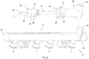
- Figures 21 and 22 illustrate a fitting 92 not part of the invention, in turn comprising an inlet 93, an inlet duct 93a and an outlet duct 93b, axial to or aligned with each other, wherein said outlet duct 93b is directly applied to an inlet 3d of the duct 2.
- a connector (a quick connector or a nipple or the like, or a bayonet or threaded connector), or a welded joint, for connecting the fitting 92 to the inlet 3d.
- the sensor 1' is slightly different from the previously described sensor 1, because it has no control and measurement circuitry.
- the control and measurement circuitry must be located remotely from the sensor 1'. This is interesting when said control circuitry is comprised in another electronic circuit of the vehicle, such as an engine management electronic circuit or control unit, resulting in obvious economical advantages.
- the housing 5 and the electric connector 7 are replaced by a base or housing 95 connected to the bender 14, from which the electric wires or conductors 94 extend.
- the base 95 is coupled to the seat 90 of the fitting 92, with which it is aligned by means of a locating rib 96 to be engaged into a homologous cutout 97 present on the fitting 92, thus providing means ensuring an accurate positioning of the sensor 1' with respect to the fitting 92.
- the senor 1' is secured and held in position by suitable fastening means, such as screws (not shown in the drawings) inserted into the pairs of holes 98,99 provided on the fitting 92 and on the base 95, although other fastening means may be alternatively used, such as a quick coupling, a bayonet coupling, a thread or a weld.
- suitable fastening means such as screws (not shown in the drawings) inserted into the pairs of holes 98,99 provided on the fitting 92 and on the base 95, although other fastening means may be alternatively used, such as a quick coupling, a bayonet coupling, a thread or a weld.
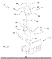
- Fig. 23 is similar to the one just described, the only difference being the arrangement of the sensor 1', which in this case is positioned substantially perpendicular to the duct 2; such an arrangement may prove to be interesting when a portion of the duct 2', including the inlet 3b, is only accessible from a direction perpendicular to said duct 2.
- the fitting 92' comprises a fuel inlet 93' and a seat 90' that houses the sensor 1', which perform the same functions as the inlet 93 and the seat 90 previously described, but are positioned in a different manner.
- the inlet 93' has its axis parallel to that of the duct 2, while the axis of the seat 90' is perpendicular to the axis of said duct 2, thus making it possible to position the sensor 1' in a manner such that it is substantially perpendicular to the duct 2, resulting in the above-mentioned advantages.
- connection between the fitting 92' and the duct 2 is made in a manner similar to the one described for the previous variant, i.e. one may use a connector (a quick connector or a nipple or the like, or a bayonet or threaded connector) or a welded joint.
- a connector a quick connector or a nipple or the like, or a bayonet or threaded connector
- the present invention is not only applicable to the "bender” sensors taken into consideration so far, but also to other types of sensors, provided that they are suitable for detecting properties of the combustible fluid as previously explained.
- Figures 27 and 28 respectively show an acoustic sensor 1' and an optical sensor 1".
- the senor 1' comprises an transceiver 112 of acoustic waves, such as ultrasound or sound waves, whose shape and/or coupling are similar to those of the "bender" sensor of the previous examples; therefore, said sensor 1' comprises or is associated with a fitting body (5, 62, 62' (2003)) adapted to be connected and/or secured to the fuel duct 2 in a way wholly similar to the one already described, to which reference should be made for the sake of brevity.
- a fitting body (5, 62, 62' —) adapted to be connected and/or secured to the fuel duct 2 in a way wholly similar to the one already described, to which reference should be made for the sake of brevity.
- the waves emitted with a preset frequency by the transceiver 112 are reflected by the combustible fluid and are then received by the same transceiver, with which a per se known electronic board is associated (not shown in Fig. 27 because it is similar to the one already described).
- the acoustic signal reflected by the fluid is then processed in order to provide information about the density and/or viscosity of the combustible fluid, as well as about its velocity and the like; to this end, the speed of propagation of sound in the medium, the Doppler effect, etc. may be used.
- the senor 1" is an optical one and comprises a photocell 114 and a light source 115 optically coupled thereto and positioned at the end of a support arm 113.
- the latter may be advantageously exploited for supplying power to the source 115, which may be of any type suitable for operating in the combustible fluid, e.g. a LED.
- the sensor 1" allows detecting the properties of the fuel circulating in the duct 2, such as density, or the presence of gas bubbles or water phases emulsified in the fuel, by using in this case optical parameters such as refraction and reflection of the luminous rays by the combustible fluid.
- the shape of the sensor 1" is similar to that used in the other embodiments, it comprising or being associated with a fitting body (5, 62, 62'...), so that it can be applied to a fuel duct 2 in accordance with the above teachings, to which reference should be made to avoid inappropriate repetitions.
- any sensor comprising at least one active element, such as an electrode or an arm like the support arm 113, extending in the fuel duct 2 or in the fitting body 52, 52', 62 etc. as aforementioned, can be advantageously employed in the present invention.
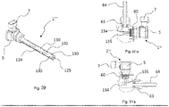
- Figure 29 shows a sensor 1''' comprising a pair of axial electrodes 124, 125, the first of which has a tubular shape and is external to the second one, which consists of a conductive wire or bar; on the outer electrode 124 there are holes or apertures 130 for the passage of the combustible fluid, the electric properties of which, such as resistivity, capacity, etc., can be detected in accordance with the prior art (in fact, axial sensors are known, for example, from US 4,806,847 , wherein they are however employed for tanks, or at any rate not in fuel ducts).
- the sensor 1' v comprises a pair of projecting elements 134 and 135, which in a preferred embodiment consist of two electrodes, but which may be probes or other elements suitable for detecting properties of the combustible fluid.
- the sensor 1' v is housed in the fitting 62', in one case ( Figs. 30 , 30a ) in the seat 60 at the end of the fitting 62', which is aligned along a longitudinal axis of the fitting 62' with the initial portion of the coupling 80 connected to the same fitting, whereas in the other case the position of the inlet 63 and of the seat 60 with the sensor 1' v is reversed, i.e. the seat 60 is orthogonal or inclined relative to said longitudinal axis.
- the latter may also be considered to be the axis of the fuel outlet portion of the fitting body 62', to which the initial portion of the coupling 80 is connected.
- the fastening or supporting means may be reversed; in other words, the parts associated with the sensor 1,1' or with the fitting 52, 52', 62, 62', 62", 62''', 62 IV , 62 V , 62 VI , 92, 92' may be associated with the duct 2, or vice versa.
Landscapes
- Engineering & Computer Science (AREA)
- Chemical & Material Sciences (AREA)
- Combustion & Propulsion (AREA)
- Mechanical Engineering (AREA)
- General Engineering & Computer Science (AREA)
- Fuel-Injection Apparatus (AREA)
Claims (16)
- Anordnung einer Vorrichtung zum Detektieren wenigstens eines Parameters eines Kraftstoffs oder Gemischen davon, der beziehungsweise die einer Brennkraftmaschine zugeführt wird beziehungsweise werden, wobei die Anordnung Sensormittel (1, 1') umfasst, um mit dem Kraftstoff oder mit den Gemischen davon wenigstens teilweise in Kontakt zu stehen, wobei die Sensormittel (1, 1') außen einer Leitung (2) von dem "Kraftstoffverteilerrohr"-Typ, von dem Typ eines "gemeinsamen Verteilerrohrs" und von ähnlichen Typen, um den Kraftstoff oder die Gemische davon der Kraftmaschine zuzuführen, zugeordnet sind, wobei das Sensormittel (1, 1') in einem Sitz eines Körpers oder einer Armatur aufgenommen ist, der bzw. die ein Auslassröhrenelement oder eine Kupplung (80) umfasst, das bzw. die auslassseitig einem Einlass (3b) der Kraftstoffleitung (2) zugeordnet oder mit ihm verbunden ist, und wobei die Anordnung Befestigungs- oder Stützmittel (86, 86', 86", 86''', 86IV, 86V, 86VI, 88, 89) zum mechanischen Befestigen und/oder Stützen der Sensormittel (1, 1') oder des Gehäusesitzes (50, 60, 90, 90') davon oder der Armatur (52, 52', 62, 62', 62", 62''', 62IV, 62V, 62VI, 92, 92') an der Kraftstoffleitung (2) umfasst, die in Verbindung mit wenigstens zwei verschiedenen oder beabstandeten Punkten, einem im Wesentlichen an einer Zwischen- oder Endposition der Leitung und einem anderen an wenigstens einem Punkt, der sich im Wesentlichen an einer Endposition oder gegenüberliegenden Position oder Zwischenposition des Kraftstoffrohrs befindet, im Wesentlichen an die Kraftstoffleitung angrenzen, sodass sich die Leitung (2) und der Sensor (1) im Wesentlichen als ein starres Teil verhalten.
- Anordnung gemäß Anspruch 1, wobei sich die Sensormittel (1, 1') vollständig oder hauptsächlich außerhalb der Leitung (2) befinden und wobei die Sensormittel (1, 1') gemäß wenigstens einer der folgenden Alternativen angeordnet sind:- angrenzend an die oder in der Nähe der Leitung (2), wobei sie vorwiegend parallel zu der Achse davon verlaufen;- angrenzend an die oder in der Nähe der Leitung (2), wobei sie vorwiegend radial in Bezug auf die Achse der Leitung (2) verlaufen.
- Anordnung gemäß Anspruch 1 oder 2, wobei die Sensormittel (1, 1') einem Gehäuse (5, 95) oder einer Armatur (52, 52', 62, 62', 62", 62''', 62IV, 62V, 62VI, 92, 92') in Fluidverbindung mit der Leitung (2) zugeordnet oder in es bzw. sie integriert sind, um den Kraftstoff oder die Gemische davon zuzuführen.
- Anordnung gemäß Anspruch 3, wobei die Sensormittel (1, 1') oder das Gehäuse (5, 95) oder die Armatur (52, 52', 62, 62', 62", 62''', 62IV, 62V, 62VI, 92, 92') der Kraftstoffleitung (2), insbesondere einem Ende davon oder an einer Position, die daran angrenzend, dazu parallel oder radial ist, zugeordnet oder lösbar daran befestigt sind.
- Anordnung gemäß Anspruch 3 oder 4, wobei in der Armatur (52, 52', 62, 62', 62", 62''', 62IV, 62V, 62VI, 92, 92') ein Kraftstoffweg definiert ist, der wenigstens zwischen einem Einlass (53, 54, 63, 64, 93, 93') und einem Auslass (56, 56', 58, 80, 80') verläuft, wobei sich ein Sitz (50, 60, 90, 90') zum Aufnehmen der Sensormittel (1, 1') wenigstens teilweise entlang des Wegs oder an einer Zwischenposition befindet.
- Anordnung gemäß einem der vorhergehenden Ansprüche, wobei das Auslassröhrenelement oder die Kupplung (80) und die Befestigungs- oder Stützmittel (86, 86', 86", 86''', 86IV, 86V, 86VI, 88, 89) die Sensormittel (1, 1') mit der Kraftstoffleitung (2) entsprechend wenigstens zwei verschiedenen Orten davon verbinden.
- Anordnung gemäß Anspruch 6, wobei die Befestigungs- oder Stützmittel (86, 86', 86", 86''', 86IV, 86V, 86VI, 88, 89) eine Halterung (86, 86', 86", 86''', 86IV, 86V, 86VI) umfassen.
- Anordnung gemäß Anspruch 6 oder 7, wobei die Befestigungs- oder Stützmittel (86, 86', 86", 86''', 86IV, 86V, 86VI, 88, 89) oder wenigstens ein Teil davon an der Kraftstoffleitung (2) lösbar befestigt werden können.
- Anordnung gemäß einem der vorhergehenden Ansprüche, wobei die Befestigungs- oder Stützmittel (86, 86', 86", 86''', 86IV, 86V, 86VI, 88, 89) zum mechanischen Befestigen und/oder Stützen der Sensormittel (1, 1') oder des Gehäusesitzes (50, 60, 90, 90') davon oder der Armatur (52, 52', 62, 62', 62", 62''', 62IV, 62V, 62VI, 92, 92') eine Schnellkupplung (70, 81) umfassen, die den Einbau im Wesentlichen durch eine einzelne Einführungsbewegung, insbesondere entlang einer Achse im Wesentlichen parallel oder senkrecht zu der der Leitung (2), ermöglicht, wobei die Schnellkupplung (70, 81) an wenigstens einer der folgenden Positionen angeordnet ist:- bei einem Einlass (3a, 3b, 3b', 3b", 3b''', 3bIV, 3bVI, 3c, 3d) der Leitung (2),- bei dem Auslass der Armatur (62) oder bei einer Zwischenposition der Armatur (62).
- Anordnung gemäß Anspruch 9, wobei die Schnellkupplung von dem Typ ist, der für Hydraulikleitungen ausgelegt ist.
- Anordnung gemäß einem der Ansprüche 3 bis 10, die eine Kupplung (80, 80') zum Verbinden mit der Kraftstoffleitung (2) umfasst, deren Enden jeweils mit der Armatur (62, 62', 62", 62''', 62IV, 62V, 62VI) und mit der Kraftstoffleitung (2) gekuppelt sind, bevorzugt auf eine lösbare Weise.
- Anordnung gemäß einem der vorhergehenden Ansprüche, wobei die Sensormittel (1, 1') von einem oder mehreren der folgenden Typen sind: elektrisch, piezoelektrisch, schwingend, magnetisch, elektromagnetisch, optisch, akustisch, resistiv, kapazitiv, induktiv.
- Anordnung gemäß Anspruch 12, wobei die Sensormittel (1, 1') ein piezoelektrisches Element oder eine piezoelektrische Biegeeinrichtung (14), das bzw. die insbesondere dafür ausgelegt ist, Kraftstoffviskositätsänderungen zu detektieren, umfassen, oder wobei die Sensormittel (1, 1') einen akustischen Sensor wie etwa einen Ultraschall-Sender/Empfänger (112), der insbesondere dafür ausgelegt ist, Änderungen der Ausbreitungsgeschwindigkeit von Schall in dem Kraftstoff zu detektieren, umfassen, oder wobei die Sensormittel (1, 1') einen optischen Sensor (114, 115) wie etwa einen optischen Empfänger (114) und eine Lichtquelle oder einen Lichtsender (115), der insbesondere dafür ausgelegt ist, Kraftstofftrübungsänderungen zu detektieren, umfassen.
- Anordnung gemäß einem der Ansprüche 5 bis 13, die wenigstens ein Element (8), das mit den Sensormitteln (1, 1') zusammenwirkt, um die Letzteren in dem jeweiligen Aufnahmesitz (50, 60, 90, 90') oder in der Armatur (52, 52', 62, 62', 62", 62''', 62IV, 62V, 62VI, 92, 92') zu befestigen, wie etwa eine Klemme oder einen Haken oder eine Schweißverbindung oder eine Klebeverbindung, umfasst.
- Leitung (2) zum Zuführen von Kraftstoff zu einer Brennkraftmaschine, wobei die Leitung eine Anordnung gemäß einem der Ansprüche 1-14 umfasst und wenigstens einen Kraftstoffeinlass (3a, 3b, 3b', 3b", 3b''', 3bIV, 3bVI, 3c, 3d) und mehrere Kraftstoffauslässe (4) enthält, dadurch gekennzeichnet, dass sie Kupplungsmittel (3a, 3b, 3b', 3b", 3b''', 3bIV, 3bVI, 3c, 3d, 8, 58, 70, 80, 80', 81, 82, 86, 86', 86", 86''', 86IV, 86V, 86VI, 87) umfasst oder dass ihr diese zugeordnet sind, die mit einem Außensensor (1, 1') wie etwa einem Hydraulik- oder Fluidkopplungsmittel (3a, 3b, 3b', 3b", 3b''', 3bIV, 3bVI, 3c, 3d, 58, 70, 80, 80', 81) ausgestattet sind, wobei sie vorzugsweise außerdem Befestigungs- oder Stützmittel (8, 58, 82, 86, 86', 86", 86''', 86IV, 86V, 86VI, 87) für eine Kraftstoffdetektionsvorrichtung (D) umfasst.
- Leitung gemäß Anspruch 15, wobei die Befestigungs- oder Stützmittel (86, 86', 86", 86''', 86IV, 86V, 86VI, 88, 89) eine oder mehrere der folgenden Alternativen umfassen:- eine Schnellkupplung (70, 81), die im Wesentlichen den Einbau durch eine einzelne Einführungsbewegung, insbesondere entlang einer Achse, die zu der der Leitung (2) im Wesentlichen parallel oder senkrecht ist, ermöglicht,- ein Gewinde (58), das an einem Ende der Leitung angeordnet ist;- ein Kunststoffmaterial, das an einem Ende der Leitung geformt ist,- eine Halterung (86, 86', 86", 86''', 86IV, 86V, 86VI).
Applications Claiming Priority (2)
| Application Number | Priority Date | Filing Date | Title |
|---|---|---|---|
| IT000090A ITTO20120090A1 (it) | 2012-02-03 | 2012-02-03 | Dispositivo e/o condotto per la rilevazione del combustibile alimentato ad un motore a combustione interna |
| PCT/IB2013/050857 WO2013114324A1 (en) | 2012-02-03 | 2013-02-01 | Device and/or duct for detecting fuel fed to an internal combustion engine |
Publications (2)
| Publication Number | Publication Date |
|---|---|
| EP2809942A1 EP2809942A1 (de) | 2014-12-10 |
| EP2809942B1 true EP2809942B1 (de) | 2020-01-01 |
Family
ID=46001437
Family Applications (1)
| Application Number | Title | Priority Date | Filing Date |
|---|---|---|---|
| EP13712353.5A Active EP2809942B1 (de) | 2012-02-03 | 2013-02-01 | Vorrichtung und/oder leitung zur erkennung des einem verbrennungsmotor zugeführten brennstoffs |
Country Status (5)
| Country | Link |
|---|---|
| EP (1) | EP2809942B1 (de) |
| CN (1) | CN104145113B (de) |
| ES (1) | ES2779034T3 (de) |
| IT (1) | ITTO20120090A1 (de) |
| WO (1) | WO2013114324A1 (de) |
Families Citing this family (5)
| Publication number | Priority date | Publication date | Assignee | Title |
|---|---|---|---|---|
| CN107076082B (zh) * | 2014-11-19 | 2022-12-20 | 大陆汽车有限公司 | 用于内燃机的燃料轨组件 |
| US11181089B2 (en) | 2019-02-20 | 2021-11-23 | Ford Global Technologies, Llc | Fuel composition and aging estimation |
| US10801462B2 (en) | 2019-02-20 | 2020-10-13 | Ford Global Technologies, Llc | Fuel composition and aging estimation |
| US10801428B2 (en) | 2019-02-20 | 2020-10-13 | Ford Global Technologies, Llc | Fuel composition and aging estimation |
| GB2591999B (en) * | 2020-02-05 | 2022-05-04 | Delphi Automotive Systems Lux | Common rail housing for a fuel delivery system |
Citations (1)
| Publication number | Priority date | Publication date | Assignee | Title |
|---|---|---|---|---|
| US6885199B2 (en) * | 2001-05-17 | 2005-04-26 | Siemens Vdo Automotive Corp. | Fuel sensor |
Family Cites Families (12)
| Publication number | Priority date | Publication date | Assignee | Title |
|---|---|---|---|---|
| US5834638A (en) * | 1996-03-04 | 1998-11-10 | Ford Motor Company | Fuel sensor |
| US6044694A (en) * | 1996-08-28 | 2000-04-04 | Videojet Systems International, Inc. | Resonator sensors employing piezoelectric benders for fluid property sensing |
| DE10025817C2 (de) * | 2000-05-24 | 2002-06-20 | Raymond A & Cie | Lösbare Schnellkupplung mit Sicherheitsverrastung |
| DE10305950B4 (de) * | 2003-02-12 | 2006-03-02 | Daimlerchrysler Ag | Einspritzsystem und thermischer Massenflusssensor für ein solches |
| ATE444442T1 (de) * | 2006-04-12 | 2009-10-15 | Man B & W Diesel As | Grosser zweitakt-kreuzkopf-dieselmotor vom gleichstromtyp |
| DE602006002823D1 (de) * | 2006-08-16 | 2008-10-30 | Delphi Tech Inc | Schnellkupplung |
| DE102007039892A1 (de) * | 2007-08-23 | 2009-02-26 | Continental Automotive Gmbh | Einspritzanlage für eine Brennkraftmaschine |
| DE102008017151B3 (de) * | 2008-04-03 | 2009-08-27 | Continental Automotive Gmbh | Kraftstoff-Einspritzsystem für eine Brennkraftmaschine |
| ITTO20080271A1 (it) * | 2008-04-08 | 2009-10-09 | Eltek Spa | "dispositivo di riscaldamento per condotti di alimentazione del combustibile, condotto di alimentazione del combustibile e motore a combustione" |
| DE102008035494B4 (de) * | 2008-07-30 | 2022-10-27 | Mercedes-Benz Group AG | Railbaugruppe einer Kraftstoffeinspritzanlage |
| IT1391187B1 (it) * | 2008-08-01 | 2011-11-18 | Eltek Spa | Dispositivo sensore di pressione |
| IT1396306B1 (it) * | 2009-11-06 | 2012-11-16 | Eltek Spa | Riscaldatore elettrico, dispositivo di riscaldamento e sistema di riscaldamento. |
-
2012
- 2012-02-03 IT IT000090A patent/ITTO20120090A1/it unknown
-
2013
- 2013-02-01 EP EP13712353.5A patent/EP2809942B1/de active Active
- 2013-02-01 ES ES13712353T patent/ES2779034T3/es active Active
- 2013-02-01 CN CN201380007964.2A patent/CN104145113B/zh active Active
- 2013-02-01 WO PCT/IB2013/050857 patent/WO2013114324A1/en not_active Ceased
Patent Citations (1)
| Publication number | Priority date | Publication date | Assignee | Title |
|---|---|---|---|---|
| US6885199B2 (en) * | 2001-05-17 | 2005-04-26 | Siemens Vdo Automotive Corp. | Fuel sensor |
Also Published As
| Publication number | Publication date |
|---|---|
| WO2013114324A1 (en) | 2013-08-08 |
| EP2809942A1 (de) | 2014-12-10 |
| ITTO20120090A1 (it) | 2013-08-04 |
| CN104145113A (zh) | 2014-11-12 |
| BR112014019152A2 (pt) | 2019-12-03 |
| CN104145113B (zh) | 2017-09-22 |
| ES2779034T3 (es) | 2020-08-13 |
| BR112014019152A8 (pt) | 2017-07-11 |
Similar Documents
| Publication | Publication Date | Title |
|---|---|---|
| WO2013114324A1 (en) | Device and/or duct for detecting fuel fed to an internal combustion engine | |
| US7360450B2 (en) | Flowmeter | |
| US9683874B2 (en) | Universal mounting head construction for liquid level transducers and the like | |
| CN103016228A (zh) | 燃油轨及使用该燃油轨的燃油喷射装置 | |
| CN101796377A (zh) | 具有基于超声波的液位传感器的燃油输送单元 | |
| ITTO20110258A1 (it) | Sensore e/o condotto per la rilevazione di liquidi, in particolare combustibili per autoveicoli | |
| CN107076591B (zh) | 热式流量计 | |
| CN108369120A (zh) | 空气质量流量计 | |
| EP2810043B1 (de) | Sensor und verfahren zur messung der eigenschaften einer flüssigkeit mittels eines sensorelementes | |
| BRPI0720456A2 (pt) | Sistemas e métodos para detectar composição de combustível utilizando propagação de onda emf | |
| US7096726B2 (en) | Fuel injector system diagnostic system | |
| CN104024626B (zh) | 气缸盖 | |
| US11248510B2 (en) | Connection head with a return cavity | |
| KR20160069562A (ko) | 연료펌프모듈의 초음파 레벨 및 알코올 농도센서 일체장치 | |
| RU2442014C2 (ru) | Подающий блок | |
| BR112014019152B1 (pt) | Dispositivo e/ou duto para detectar alimentação de combustível a um motor de combustão interna | |
| CN102434334A (zh) | 传感器安装构造 | |
| JP2008202512A (ja) | 燃料供給装置 | |
| JP2020176970A (ja) | 物理量測定装置 | |
| US11415443B2 (en) | Flow rate detector | |
| EP2700805B1 (de) | Verlängerungsteil, Einspritzventil und Brennstoffversorgungsanordnung | |
| KR101370863B1 (ko) | 차량용 맵센서 | |
| US20090079445A1 (en) | Isolated fuel sensor | |
| JP2014142204A (ja) | 筒形電極、およびそれを用いた燃料性状センサ | |
| JP6941172B2 (ja) | 物理量検出装置 |
Legal Events
| Date | Code | Title | Description |
|---|---|---|---|
| PUAI | Public reference made under article 153(3) epc to a published international application that has entered the european phase |
Free format text: ORIGINAL CODE: 0009012 |
|
| 17P | Request for examination filed |
Effective date: 20140724 |
|
| AK | Designated contracting states |
Kind code of ref document: A1 Designated state(s): AL AT BE BG CH CY CZ DE DK EE ES FI FR GB GR HR HU IE IS IT LI LT LU LV MC MK MT NL NO PL PT RO RS SE SI SK SM TR |
|
| AX | Request for extension of the european patent |
Extension state: BA ME |
|
| DAX | Request for extension of the european patent (deleted) | ||
| STAA | Information on the status of an ep patent application or granted ep patent |
Free format text: STATUS: EXAMINATION IS IN PROGRESS |
|
| 17Q | First examination report despatched |
Effective date: 20170711 |
|
| GRAP | Despatch of communication of intention to grant a patent |
Free format text: ORIGINAL CODE: EPIDOSNIGR1 |
|
| STAA | Information on the status of an ep patent application or granted ep patent |
Free format text: STATUS: GRANT OF PATENT IS INTENDED |
|
| INTG | Intention to grant announced |
Effective date: 20190823 |
|
| GRAS | Grant fee paid |
Free format text: ORIGINAL CODE: EPIDOSNIGR3 |
|
| GRAA | (expected) grant |
Free format text: ORIGINAL CODE: 0009210 |
|
| STAA | Information on the status of an ep patent application or granted ep patent |
Free format text: STATUS: THE PATENT HAS BEEN GRANTED |
|
| AK | Designated contracting states |
Kind code of ref document: B1 Designated state(s): AL AT BE BG CH CY CZ DE DK EE ES FI FR GB GR HR HU IE IS IT LI LT LU LV MC MK MT NL NO PL PT RO RS SE SI SK SM TR |
|
| REG | Reference to a national code |
Ref country code: GB Ref legal event code: FG4D |
|
| REG | Reference to a national code |
Ref country code: CH Ref legal event code: EP Ref country code: AT Ref legal event code: REF Ref document number: 1220072 Country of ref document: AT Kind code of ref document: T Effective date: 20200115 |
|
| REG | Reference to a national code |
Ref country code: IE Ref legal event code: FG4D |
|
| REG | Reference to a national code |
Ref country code: DE Ref legal event code: R096 Ref document number: 602013064575 Country of ref document: DE |
|
| REG | Reference to a national code |
Ref country code: SE Ref legal event code: TRGR |
|
| REG | Reference to a national code |
Ref country code: NO Ref legal event code: T2 Effective date: 20200101 |
|
| REG | Reference to a national code |
Ref country code: NL Ref legal event code: MP Effective date: 20200101 |
|
| REG | Reference to a national code |
Ref country code: LT Ref legal event code: MG4D |
|
| PG25 | Lapsed in a contracting state [announced via postgrant information from national office to epo] |
Ref country code: FI Free format text: LAPSE BECAUSE OF FAILURE TO SUBMIT A TRANSLATION OF THE DESCRIPTION OR TO PAY THE FEE WITHIN THE PRESCRIBED TIME-LIMIT Effective date: 20200101 Ref country code: PT Free format text: LAPSE BECAUSE OF FAILURE TO SUBMIT A TRANSLATION OF THE DESCRIPTION OR TO PAY THE FEE WITHIN THE PRESCRIBED TIME-LIMIT Effective date: 20200527 Ref country code: LT Free format text: LAPSE BECAUSE OF FAILURE TO SUBMIT A TRANSLATION OF THE DESCRIPTION OR TO PAY THE FEE WITHIN THE PRESCRIBED TIME-LIMIT Effective date: 20200101 Ref country code: RS Free format text: LAPSE BECAUSE OF FAILURE TO SUBMIT A TRANSLATION OF THE DESCRIPTION OR TO PAY THE FEE WITHIN THE PRESCRIBED TIME-LIMIT Effective date: 20200101 Ref country code: CZ Free format text: LAPSE BECAUSE OF FAILURE TO SUBMIT A TRANSLATION OF THE DESCRIPTION OR TO PAY THE FEE WITHIN THE PRESCRIBED TIME-LIMIT Effective date: 20200101 Ref country code: NL Free format text: LAPSE BECAUSE OF FAILURE TO SUBMIT A TRANSLATION OF THE DESCRIPTION OR TO PAY THE FEE WITHIN THE PRESCRIBED TIME-LIMIT Effective date: 20200101 |
|
| REG | Reference to a national code |
Ref country code: ES Ref legal event code: FG2A Ref document number: 2779034 Country of ref document: ES Kind code of ref document: T3 Effective date: 20200813 |
|
| PG25 | Lapsed in a contracting state [announced via postgrant information from national office to epo] |
Ref country code: LV Free format text: LAPSE BECAUSE OF FAILURE TO SUBMIT A TRANSLATION OF THE DESCRIPTION OR TO PAY THE FEE WITHIN THE PRESCRIBED TIME-LIMIT Effective date: 20200101 Ref country code: IS Free format text: LAPSE BECAUSE OF FAILURE TO SUBMIT A TRANSLATION OF THE DESCRIPTION OR TO PAY THE FEE WITHIN THE PRESCRIBED TIME-LIMIT Effective date: 20200501 Ref country code: GR Free format text: LAPSE BECAUSE OF FAILURE TO SUBMIT A TRANSLATION OF THE DESCRIPTION OR TO PAY THE FEE WITHIN THE PRESCRIBED TIME-LIMIT Effective date: 20200402 Ref country code: HR Free format text: LAPSE BECAUSE OF FAILURE TO SUBMIT A TRANSLATION OF THE DESCRIPTION OR TO PAY THE FEE WITHIN THE PRESCRIBED TIME-LIMIT Effective date: 20200101 Ref country code: BG Free format text: LAPSE BECAUSE OF FAILURE TO SUBMIT A TRANSLATION OF THE DESCRIPTION OR TO PAY THE FEE WITHIN THE PRESCRIBED TIME-LIMIT Effective date: 20200401 |
|
| REG | Reference to a national code |
Ref country code: CH Ref legal event code: PL |
|
| REG | Reference to a national code |
Ref country code: DE Ref legal event code: R097 Ref document number: 602013064575 Country of ref document: DE |
|
| REG | Reference to a national code |
Ref country code: BE Ref legal event code: MM Effective date: 20200229 |
|
| PG25 | Lapsed in a contracting state [announced via postgrant information from national office to epo] |
Ref country code: SM Free format text: LAPSE BECAUSE OF FAILURE TO SUBMIT A TRANSLATION OF THE DESCRIPTION OR TO PAY THE FEE WITHIN THE PRESCRIBED TIME-LIMIT Effective date: 20200101 Ref country code: EE Free format text: LAPSE BECAUSE OF FAILURE TO SUBMIT A TRANSLATION OF THE DESCRIPTION OR TO PAY THE FEE WITHIN THE PRESCRIBED TIME-LIMIT Effective date: 20200101 Ref country code: LU Free format text: LAPSE BECAUSE OF NON-PAYMENT OF DUE FEES Effective date: 20200201 Ref country code: RO Free format text: LAPSE BECAUSE OF FAILURE TO SUBMIT A TRANSLATION OF THE DESCRIPTION OR TO PAY THE FEE WITHIN THE PRESCRIBED TIME-LIMIT Effective date: 20200101 Ref country code: MC Free format text: LAPSE BECAUSE OF FAILURE TO SUBMIT A TRANSLATION OF THE DESCRIPTION OR TO PAY THE FEE WITHIN THE PRESCRIBED TIME-LIMIT Effective date: 20200101 Ref country code: SK Free format text: LAPSE BECAUSE OF FAILURE TO SUBMIT A TRANSLATION OF THE DESCRIPTION OR TO PAY THE FEE WITHIN THE PRESCRIBED TIME-LIMIT Effective date: 20200101 Ref country code: DK Free format text: LAPSE BECAUSE OF FAILURE TO SUBMIT A TRANSLATION OF THE DESCRIPTION OR TO PAY THE FEE WITHIN THE PRESCRIBED TIME-LIMIT Effective date: 20200101 |
|
| PLBE | No opposition filed within time limit |
Free format text: ORIGINAL CODE: 0009261 |
|
| STAA | Information on the status of an ep patent application or granted ep patent |
Free format text: STATUS: NO OPPOSITION FILED WITHIN TIME LIMIT |
|
| REG | Reference to a national code |
Ref country code: AT Ref legal event code: MK05 Ref document number: 1220072 Country of ref document: AT Kind code of ref document: T Effective date: 20200101 |
|
| PG25 | Lapsed in a contracting state [announced via postgrant information from national office to epo] |
Ref country code: LI Free format text: LAPSE BECAUSE OF NON-PAYMENT OF DUE FEES Effective date: 20200229 Ref country code: CH Free format text: LAPSE BECAUSE OF NON-PAYMENT OF DUE FEES Effective date: 20200229 |
|
| 26N | No opposition filed |
Effective date: 20201002 |
|
| PG25 | Lapsed in a contracting state [announced via postgrant information from national office to epo] |
Ref country code: IE Free format text: LAPSE BECAUSE OF NON-PAYMENT OF DUE FEES Effective date: 20200201 Ref country code: AT Free format text: LAPSE BECAUSE OF FAILURE TO SUBMIT A TRANSLATION OF THE DESCRIPTION OR TO PAY THE FEE WITHIN THE PRESCRIBED TIME-LIMIT Effective date: 20200101 |
|
| PG25 | Lapsed in a contracting state [announced via postgrant information from national office to epo] |
Ref country code: SI Free format text: LAPSE BECAUSE OF FAILURE TO SUBMIT A TRANSLATION OF THE DESCRIPTION OR TO PAY THE FEE WITHIN THE PRESCRIBED TIME-LIMIT Effective date: 20200101 Ref country code: PL Free format text: LAPSE BECAUSE OF FAILURE TO SUBMIT A TRANSLATION OF THE DESCRIPTION OR TO PAY THE FEE WITHIN THE PRESCRIBED TIME-LIMIT Effective date: 20200101 Ref country code: BE Free format text: LAPSE BECAUSE OF NON-PAYMENT OF DUE FEES Effective date: 20200229 |
|
| PG25 | Lapsed in a contracting state [announced via postgrant information from national office to epo] |
Ref country code: TR Free format text: LAPSE BECAUSE OF FAILURE TO SUBMIT A TRANSLATION OF THE DESCRIPTION OR TO PAY THE FEE WITHIN THE PRESCRIBED TIME-LIMIT Effective date: 20200101 Ref country code: MT Free format text: LAPSE BECAUSE OF FAILURE TO SUBMIT A TRANSLATION OF THE DESCRIPTION OR TO PAY THE FEE WITHIN THE PRESCRIBED TIME-LIMIT Effective date: 20200101 Ref country code: CY Free format text: LAPSE BECAUSE OF FAILURE TO SUBMIT A TRANSLATION OF THE DESCRIPTION OR TO PAY THE FEE WITHIN THE PRESCRIBED TIME-LIMIT Effective date: 20200101 |
|
| PG25 | Lapsed in a contracting state [announced via postgrant information from national office to epo] |
Ref country code: MK Free format text: LAPSE BECAUSE OF FAILURE TO SUBMIT A TRANSLATION OF THE DESCRIPTION OR TO PAY THE FEE WITHIN THE PRESCRIBED TIME-LIMIT Effective date: 20200101 Ref country code: AL Free format text: LAPSE BECAUSE OF FAILURE TO SUBMIT A TRANSLATION OF THE DESCRIPTION OR TO PAY THE FEE WITHIN THE PRESCRIBED TIME-LIMIT Effective date: 20200101 |
|
| PGFP | Annual fee paid to national office [announced via postgrant information from national office to epo] |
Ref country code: NO Payment date: 20230222 Year of fee payment: 11 |
|
| PGFP | Annual fee paid to national office [announced via postgrant information from national office to epo] |
Ref country code: SE Payment date: 20230220 Year of fee payment: 11 |
|
| P01 | Opt-out of the competence of the unified patent court (upc) registered |
Effective date: 20230421 |
|
| PGFP | Annual fee paid to national office [announced via postgrant information from national office to epo] |
Ref country code: ES Payment date: 20240301 Year of fee payment: 12 |
|
| REG | Reference to a national code |
Ref country code: SE Ref legal event code: EUG |
|
| PG25 | Lapsed in a contracting state [announced via postgrant information from national office to epo] |
Ref country code: NO Free format text: LAPSE BECAUSE OF NON-PAYMENT OF DUE FEES Effective date: 20240229 |
|
| PGFP | Annual fee paid to national office [announced via postgrant information from national office to epo] |
Ref country code: DE Payment date: 20250225 Year of fee payment: 13 |
|
| PGFP | Annual fee paid to national office [announced via postgrant information from national office to epo] |
Ref country code: FR Payment date: 20250218 Year of fee payment: 13 |
|
| PGFP | Annual fee paid to national office [announced via postgrant information from national office to epo] |
Ref country code: IT Payment date: 20250226 Year of fee payment: 13 Ref country code: GB Payment date: 20250221 Year of fee payment: 13 |
|
| PG25 | Lapsed in a contracting state [announced via postgrant information from national office to epo] |
Ref country code: SE Free format text: LAPSE BECAUSE OF NON-PAYMENT OF DUE FEES Effective date: 20240202 |
|
| REG | Reference to a national code |
Ref country code: ES Ref legal event code: FD2A Effective date: 20260326 |
|
| PG25 | Lapsed in a contracting state [announced via postgrant information from national office to epo] |
Ref country code: ES Free format text: LAPSE BECAUSE OF NON-PAYMENT OF DUE FEES Effective date: 20250202 |