EP2809906B1 - Système tampon de moteur de turbine à gaz - Google Patents
Système tampon de moteur de turbine à gaz Download PDFInfo
- Publication number
- EP2809906B1 EP2809906B1 EP13744090.5A EP13744090A EP2809906B1 EP 2809906 B1 EP2809906 B1 EP 2809906B1 EP 13744090 A EP13744090 A EP 13744090A EP 2809906 B1 EP2809906 B1 EP 2809906B1
- Authority
- EP
- European Patent Office
- Prior art keywords
- gas turbine
- turbine engine
- air supply
- bleed air
- supply
- Prior art date
- Legal status (The legal status is an assumption and is not a legal conclusion. Google has not performed a legal analysis and makes no representation as to the accuracy of the status listed.)
- Active
Links
- 239000007853 buffer solution Substances 0.000 title claims description 25
- 239000000872 buffer Substances 0.000 claims description 36
- 238000004891 communication Methods 0.000 claims description 11
- 238000001816 cooling Methods 0.000 claims description 6
- 238000000034 method Methods 0.000 claims description 6
- 230000003416 augmentation Effects 0.000 claims description 4
- 230000003190 augmentative effect Effects 0.000 claims description 4
- 238000011144 upstream manufacturing Methods 0.000 claims description 4
- 239000007789 gas Substances 0.000 description 61
- 239000000314 lubricant Substances 0.000 description 10
- 230000003750 conditioning effect Effects 0.000 description 6
- 239000000446 fuel Substances 0.000 description 5
- 239000000567 combustion gas Substances 0.000 description 4
- 230000003068 static effect Effects 0.000 description 3
- 238000009423 ventilation Methods 0.000 description 2
- 230000006835 compression Effects 0.000 description 1
- 238000007906 compression Methods 0.000 description 1
- 239000002826 coolant Substances 0.000 description 1
- 230000001419 dependent effect Effects 0.000 description 1
- 238000001514 detection method Methods 0.000 description 1
- 230000009977 dual effect Effects 0.000 description 1
- 239000000284 extract Substances 0.000 description 1
- 239000012530 fluid Substances 0.000 description 1
- 230000001050 lubricating effect Effects 0.000 description 1
- 238000005461 lubrication Methods 0.000 description 1
- 239000000463 material Substances 0.000 description 1
- 239000000203 mixture Substances 0.000 description 1
- 238000012986 modification Methods 0.000 description 1
- 230000004048 modification Effects 0.000 description 1
- 230000001052 transient effect Effects 0.000 description 1
Images

Classifications
-
- F—MECHANICAL ENGINEERING; LIGHTING; HEATING; WEAPONS; BLASTING
- F02—COMBUSTION ENGINES; HOT-GAS OR COMBUSTION-PRODUCT ENGINE PLANTS
- F02C—GAS-TURBINE PLANTS; AIR INTAKES FOR JET-PROPULSION PLANTS; CONTROLLING FUEL SUPPLY IN AIR-BREATHING JET-PROPULSION PLANTS
- F02C6/00—Plural gas-turbine plants; Combinations of gas-turbine plants with other apparatus; Adaptations of gas- turbine plants for special use
- F02C6/04—Gas-turbine plants providing heated or pressurised working fluid for other apparatus, e.g. without mechanical power output
- F02C6/06—Gas-turbine plants providing heated or pressurised working fluid for other apparatus, e.g. without mechanical power output providing compressed gas
- F02C6/08—Gas-turbine plants providing heated or pressurised working fluid for other apparatus, e.g. without mechanical power output providing compressed gas the gas being bled from the gas-turbine compressor
-
- F—MECHANICAL ENGINEERING; LIGHTING; HEATING; WEAPONS; BLASTING
- F01—MACHINES OR ENGINES IN GENERAL; ENGINE PLANTS IN GENERAL; STEAM ENGINES
- F01D—NON-POSITIVE DISPLACEMENT MACHINES OR ENGINES, e.g. STEAM TURBINES
- F01D11/00—Preventing or minimising internal leakage of working-fluid, e.g. between stages
- F01D11/02—Preventing or minimising internal leakage of working-fluid, e.g. between stages by non-contact sealings, e.g. of labyrinth type
- F01D11/04—Preventing or minimising internal leakage of working-fluid, e.g. between stages by non-contact sealings, e.g. of labyrinth type using sealing fluid, e.g. steam
- F01D11/06—Control thereof
-
- F—MECHANICAL ENGINEERING; LIGHTING; HEATING; WEAPONS; BLASTING
- F01—MACHINES OR ENGINES IN GENERAL; ENGINE PLANTS IN GENERAL; STEAM ENGINES
- F01D—NON-POSITIVE DISPLACEMENT MACHINES OR ENGINES, e.g. STEAM TURBINES
- F01D25/00—Component parts, details, or accessories, not provided for in, or of interest apart from, other groups
- F01D25/08—Cooling; Heating; Heat-insulation
- F01D25/12—Cooling
- F01D25/125—Cooling of bearings
-
- F—MECHANICAL ENGINEERING; LIGHTING; HEATING; WEAPONS; BLASTING
- F02—COMBUSTION ENGINES; HOT-GAS OR COMBUSTION-PRODUCT ENGINE PLANTS
- F02C—GAS-TURBINE PLANTS; AIR INTAKES FOR JET-PROPULSION PLANTS; CONTROLLING FUEL SUPPLY IN AIR-BREATHING JET-PROPULSION PLANTS
- F02C7/00—Features, components parts, details or accessories, not provided for in, or of interest apart form groups F02C1/00 - F02C6/00; Air intakes for jet-propulsion plants
- F02C7/04—Air intakes for gas-turbine plants or jet-propulsion plants
- F02C7/047—Heating to prevent icing
-
- F—MECHANICAL ENGINEERING; LIGHTING; HEATING; WEAPONS; BLASTING
- F02—COMBUSTION ENGINES; HOT-GAS OR COMBUSTION-PRODUCT ENGINE PLANTS
- F02C—GAS-TURBINE PLANTS; AIR INTAKES FOR JET-PROPULSION PLANTS; CONTROLLING FUEL SUPPLY IN AIR-BREATHING JET-PROPULSION PLANTS
- F02C9/00—Controlling gas-turbine plants; Controlling fuel supply in air- breathing jet-propulsion plants
- F02C9/16—Control of working fluid flow
- F02C9/18—Control of working fluid flow by bleeding, bypassing or acting on variable working fluid interconnections between turbines or compressors or their stages
-
- F—MECHANICAL ENGINEERING; LIGHTING; HEATING; WEAPONS; BLASTING
- F02—COMBUSTION ENGINES; HOT-GAS OR COMBUSTION-PRODUCT ENGINE PLANTS
- F02C—GAS-TURBINE PLANTS; AIR INTAKES FOR JET-PROPULSION PLANTS; CONTROLLING FUEL SUPPLY IN AIR-BREATHING JET-PROPULSION PLANTS
- F02C7/00—Features, components parts, details or accessories, not provided for in, or of interest apart form groups F02C1/00 - F02C6/00; Air intakes for jet-propulsion plants
- F02C7/06—Arrangements of bearings; Lubricating
-
- F—MECHANICAL ENGINEERING; LIGHTING; HEATING; WEAPONS; BLASTING
- F02—COMBUSTION ENGINES; HOT-GAS OR COMBUSTION-PRODUCT ENGINE PLANTS
- F02C—GAS-TURBINE PLANTS; AIR INTAKES FOR JET-PROPULSION PLANTS; CONTROLLING FUEL SUPPLY IN AIR-BREATHING JET-PROPULSION PLANTS
- F02C7/00—Features, components parts, details or accessories, not provided for in, or of interest apart form groups F02C1/00 - F02C6/00; Air intakes for jet-propulsion plants
- F02C7/28—Arrangement of seals
-
- F—MECHANICAL ENGINEERING; LIGHTING; HEATING; WEAPONS; BLASTING
- F05—INDEXING SCHEMES RELATING TO ENGINES OR PUMPS IN VARIOUS SUBCLASSES OF CLASSES F01-F04
- F05D—INDEXING SCHEME FOR ASPECTS RELATING TO NON-POSITIVE-DISPLACEMENT MACHINES OR ENGINES, GAS-TURBINES OR JET-PROPULSION PLANTS
- F05D2260/00—Function
- F05D2260/60—Fluid transfer
- F05D2260/601—Fluid transfer using an ejector or a jet pump
-
- Y—GENERAL TAGGING OF NEW TECHNOLOGICAL DEVELOPMENTS; GENERAL TAGGING OF CROSS-SECTIONAL TECHNOLOGIES SPANNING OVER SEVERAL SECTIONS OF THE IPC; TECHNICAL SUBJECTS COVERED BY FORMER USPC CROSS-REFERENCE ART COLLECTIONS [XRACs] AND DIGESTS
- Y02—TECHNOLOGIES OR APPLICATIONS FOR MITIGATION OR ADAPTATION AGAINST CLIMATE CHANGE
- Y02T—CLIMATE CHANGE MITIGATION TECHNOLOGIES RELATED TO TRANSPORTATION
- Y02T50/00—Aeronautics or air transport
- Y02T50/60—Efficient propulsion technologies, e.g. for aircraft
-
- Y—GENERAL TAGGING OF NEW TECHNOLOGICAL DEVELOPMENTS; GENERAL TAGGING OF CROSS-SECTIONAL TECHNOLOGIES SPANNING OVER SEVERAL SECTIONS OF THE IPC; TECHNICAL SUBJECTS COVERED BY FORMER USPC CROSS-REFERENCE ART COLLECTIONS [XRACs] AND DIGESTS
- Y10—TECHNICAL SUBJECTS COVERED BY FORMER USPC
- Y10T—TECHNICAL SUBJECTS COVERED BY FORMER US CLASSIFICATION
- Y10T29/00—Metal working
- Y10T29/49—Method of mechanical manufacture
- Y10T29/49316—Impeller making
- Y10T29/4932—Turbomachine making
- Y10T29/49323—Assembling fluid flow directing devices, e.g., stators, diaphragms, nozzles
Definitions
- This disclosure relates to a gas turbine engine, and more particularly to a buffer system that can communicate a buffer supply air to one or more portions of the gas turbine engine.
- Gas turbine engines typically include at least a compressor section, a combustor section and a turbine section. During operation, air is pressurized in the compressor section and is mixed with fuel and burned in the combustor section to generate hot combustion gases. The hot combustion gases are communicated through the turbine section which extracts energy from the hot combustion gases to power the compressor section and other gas turbine engine modes.
- Gas turbine engines typically include shafts that support a plurality of airfoil supporting rotors of the compressor section and the turbine section. Generally, these shafts are supported by bearing structures that define bearing compartments.
- the bearing compartments house one or more bearings and contain lubricant that is used to lubricate the bearings.
- the lubricant is contained within the bearing compartment by one or more seals. A predetermined differential pressure must be maintained across the seals so the lubricant cannot leak past the seals.
- EP 2119892 relates to a method for controlling a set point for extracting air from a compressor to provide turbine cooling air in a gas turbine engine.
- FR 2698406 relates to a procedure for pressurising the lubrication chambers of a turbine.
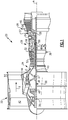
- FIG. 1 schematically illustrates a gas turbine engine 20.
- the gas turbine engine 20 disclosed herein is a two spool turbofan engine that generally incorporates a fan section 22, a compressor section 24, a combustor section 26 and a turbine section 28.
- Alternative engines might include an augmenter section (not shown) among other systems or features.
- the fan section 22 drives air along a bypass flow path B while the compressor section 24 drives air along a core flow path C for compression and communication into the combustor section 26.
- the hot combustion gases generated in the combustor section 26 are expanded through the turbine section 28.
- FIG. 1 schematically illustrates a gas turbine engine 20.
- the gas turbine engine 20 disclosed herein is a two spool turbofan engine that generally incorporates a fan section 22, a compressor section 24, a combustor section 26 and a turbine section 28.
- Alternative engines might include an augmenter section (not shown) among other systems or features.
- the fan section 22 drives air along a bypass flow path B while the compressor section 24 drives
- the gas turbine engine 20 generally includes a low speed spool 30 and a high speed spool 32 mounted for rotation about an engine centerline longitudinal axis A relative to an engine static structure 36 via several bearing structures 38. It should be understood that various bearing structures 38 at various locations may alternatively or additionally be provided.
- the low speed spool 30 generally includes an inner shaft 40 that interconnects a fan 42, a low pressure compressor 44 and a low pressure turbine 46.
- the inner shaft 40 can be connected to the fan 42 through a geared architecture 48 to drive the fan 42 at a lower speed than the low speed spool 30.
- the high speed spool 32 includes an outer shaft 50 that interconnects a high pressure compressor 52 and a high pressure turbine 54.
- the inner shaft 40 and the outer shaft 50 are supported at a plurality of points by bearing structures 38 positioned within the engine static structure 36.
- bearing structures 38 include at least a #1 bearing structure 38-1 forward of the geared architecture 48 and a #2 bearing structure 38-2 located aft of the geared architecture 48.
- a combustor 56 is arranged between the high pressure compressor 52 and the high pressure turbine 54.
- a mid-turbine frame 57 of the engine static structure 36 is arranged generally between the high pressure turbine 54 and the low pressure turbine 46.
- the mid-turbine frame 57 can support one or more bearing structures 38 in the turbine section 28.
- the inner shaft 40 and the outer shaft 50 are concentric and rotate via the bearing structures 38 about the engine centerline longitudinal axis A which is collinear with their longitudinal axes.
- the inner shaft 40 and the outer shaft 50 can be either co-rotating or counter-rotating with respect to one another.
- the core airflow C is compressed by the low pressure compressor 44 and the high pressure compressor 52, is mixed with fuel and burned in the combustor 56, and is then expanded over the high pressure turbine 54 and the low pressure turbine 46.
- the mid-turbine frame 57 includes airfoils 59 which are in the core airflow path.
- the high pressure turbine 54 and the low pressure turbine 46 rotationally drive the respective high speed spool 32 and the low speed spool 30 in response to the expansion.
- the gas turbine engine 20 is a high-bypass geared aircraft engine.
- the gas turbine engine 20 bypass ratio is greater than about six (6:1).
- the geared architecture 48 of the example gas turbine engine 20 includes an epicyclic gear train, such as a planetary gear system or other gear system.
- the example epicyclic gear train has a gear reduction ratio of greater than about 2.3.
- the geared architecture 48 enables operation of the low speed spool 30 at higher speeds which can increase the operational efficiency of the low pressure compressor 44 and low pressure turbine 46 and render increased pressure in a fewer number of stages.
- the low pressure turbine 46 pressure ratio is pressure measured prior to inlet of low pressure turbine 46 as related to the pressure at the outlet of the low pressure turbine 46 prior to an exhaust nozzle of the gas turbine engine 20.
- the bypass ratio of the gas turbine engine 20 is greater than about ten (10:1)
- the fan diameter is significantly larger than that of the low pressure compressor 44
- the low pressure turbine 46 has a pressure ratio that is greater than about 5 (5:1).
- the geared architecture 48 of this embodiment is an epicyclic gear train with a gear reduction ratio of greater than about 2.5:1. It should be understood, however, that the above parameters are only exemplary of one embodiment of a geared architecture engine and that the present disclosure is applicable to other gas turbine engines including direct drive turbofans.
- a significant amount of thrust is provided by a bypass flow B due to the high bypass ratio.
- the fan section 22 of the gas turbine engine 20 is designed for a particular flight conditiontypically cruise at about 0.8 Mach and about 10668 meters (35000 feet). This flight condition, with the gas turbine engine 20 at its best fuel consumption, is also known as bucket cruise Thrust Specific Fuel Consumption (TSFC).
- TSFC Thrust Specific Fuel Consumption
- Fan Pressure Ratio is the pressure ratio across a blade of the fan section 22 without the use of a Fan Exit Guide Vane system.
- the low Fan Pressure Ratio according to one non-limiting embodiment of the example gas turbine engine 20 is less than 1.45.
- Low Corrected Fan Tip Speed is the actual fan tip speed divided by an industry standard temperature correction of "T" / 518.7 0.5 .
- T represents the ambient temperature in degrees Rankine.
- the Low Corrected Fan Tip Speed according to one non-limiting embodiment of the example gas turbine engine 20 is less than about 1150 fps (351 m/s).
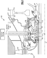
- Figure 2 illustrates a portion 100 of a gas turbine engine, such as the gas turbine engine 20.
- the portion 100 can include one or more bearing structures 38. Only one bearing structure 38 is depicted in Figure 2 to schematically illustrate its features, but this is in no way intended to limit this disclosure.
- the bearing structure 38 supports a shaft 61, such as the inner shaft 40 or the outer shaft 50, which supports a rotor assembly 63, such as a rotor assembly of the compressor section 24 or the turbine section 28, through a hub 65.
- the rotor assembly 63 carries at least one airfoil 67 for adding or extracting energy from the core airflow.
- the bearing structure 38 defines a bearing compartment BC that houses one or more bearings 71.
- the bearing compartment BC contains a lubricant for lubricating (and acting as a cooling medium to) the bearings 71.
- One or more seals 73 (two shown) contain the lubricant within the bearing compartment BC.
- the seals 73 of the bearing compartment BC must be pressurized to prevent the lubricant from leaking out during certain ground and flight conditions (both steady state and transient).
- a buffer system can be used to communicate buffer supply air to the bearing compartment BC in order to provide adequate pressurization of the seals 73 without exceeding material and/or lubricant temperature limitations. Example buffer systems that can be used for this and other purposes are detailed below.
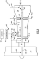
- Figure 3 illustrates an example buffer system 60 that can communicate buffer supply air 62 to a portion of the gas turbine engine 20, such as to one or more bearing compartments BC.
- bearing compartments BC-1, BC-2, BC-3, BC-4(a), BC-4(b) and BC-5 can be fed with buffer supply air 62.
- the buffer supply air 62 pressurizes the bearing compartments BC and can maintain the bearing compartments BC at an acceptable temperature.
- buffer supply air 62 could be communicated to only a single bearing compartment or could be communicated for anti-icing, ventilation, cooling and other purposes.
- the buffer system 60 includes a first bleed air supply 64 and a second bleed air supply 66.
- the buffer system 60 is a dual supply system.
- the first bleed air supply 64 is a low pressure bleed air supply
- the second bleed air supply 66 is a high pressure bleed air supply that includes a pressure that is greater than the pressure of the first bleed air supply 64.
- the first bleed air supply 64 can be sourced from the fan section 22, the low pressure compressor 44 or the high pressure compressor 52. In the illustrated non-limiting example, the first bleed air supply 64 is sourced from an upstream stage of the high pressure compressor 52. However, the first bleed air supply 64 could be sourced from any location that is upstream from the second bleed air supply 66.
- the second bleed air supply 66 can be sourced from the high pressure compressor 52, such as from a middle or downstream stage of the high pressure compressor 52. The second bleed air supply 66 could also be sourced from the low pressure compressor 44 or the fan section 22 depending on from where the first bleed air supply 64 is sourced.
- the buffer system 60 can also include a valve 68 that is in communication with both the first bleed air supply 64 and the second bleed air supply 66. Although shown schematically, the first bleed air supply 64 and the second bleed air supply 66 can be in fluid communication with the valve 68 via buffer tubing, conduits, or other passageways. Check valves may also be used to prevent the second bleed air supply 66 from backflowing into the first bleed air supply 64.
- the valve 68 can select between the first bleed air supply 64 and the second bleed air supply 66 to communicate the buffer supply air 62 to a desired portion(s) of the gas turbine engine 20.
- the buffer supply air 62 that is communicated is either the first bleed air supply 64 or the second bleed air supply 66 depending on which air supply is ultimately selected by the valve 68, as is further discussed below.
- the determination of whether to communicate the first bleed air supply 64 or the second bleed air supply 66 as the buffer supply air 62 is based on a power condition of the gas turbine engine 20.
- the term "power condition" as used in this disclosure generally refers to an operability condition of the gas turbine engine 20.
- Gas turbine engine power conditions can include low power conditions and high power conditions.
- Example low power conditions include, but are not limited to, ground operation, ground idle, and descent idle.
- Example high power conditions include, but are not limited to, takeoff, climb, and cruise conditions. It should be understood that other power conditions are also contemplated as within the scope of this disclosure.
- the valve 68 communicates the first bleed air supply 64 (which is a relatively lower pressure bleed air supply) as the buffer supply air 62 in response to identifying a high power condition of a gas turbine engine 20.
- the second bleed air supply 66 (which is a relatively higher pressure bleed air supply) is selected by the valve 68 and communicated as the buffer supply air 62 in response to detecting a low power condition of the gas turbine engine 20.
- Both the first bleed air supply 64 and the second bleed air supply 66 are intended to maintain the same minimum pressure delta across the bearing compartment seals. Low power conditions require a higher stage pressure source to contain the lubricant within the bearing compartment, while high power conditions require a lower stage pressure source.
- the buffer system 60 can use the lowest possible compressor stage to meet pressure requirements in order to minimize supply temperature and any performance impact to the gas turbine engine 20.
- the valve 68 can be a passive valve.
- a passive valve operates like a pressure regulator that can switch between two or more sources without being commanded to do so by a controller, such as an engine control (EEC).
- EEC engine control
- the valve 68 of this example uses only a single input which is directly measured to switch between the first bleed air supply 64 and the second bleed air supply 66.
- the valve 68 could also be a controller based valve.
- the buffer system 60 can include a controller 70 in communication with the valve 68 for selecting between the first bleed air supply 64 and the second bleed air supply 66.
- the controller 70 is programmed with the necessary logic for selecting between the first bleed air supply 64 and the second bleed air supply 66 in response to detecting a pre-defined power condition of the gas turbine engine 20.
- the controller 70 could also be programmed with multiple inputs.
- a sensor 99 detects a power condition of the gas turbine engine 20 and communicates a signal to the controller 70 to command modulation of the valve 68 between the first bleed air supply 64 and the second bleed air supply 66.
- the valve 68 could also be modulated to an intermediate level to intermix the first bleed air supply 64 and the second bleed air supply 66.
- this view is highly schematic. It should be understood that the sensor 99 and the controller 70 can be programmed to detect any power condition. Also, the sensor 99 can be replaced by any control associated with the gas turbine engine 20 or an associated aircraft. Also, although shown as a separate feature, the controller functionality could be incorporated into the valve 68.
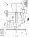
- Figure 4 illustrates an exemplary embodiment of a buffer system 160 that can communicate buffer supply air 162 to provide adequate bearing compartment seal pressurization at an acceptable temperature.
- the buffer supply air 162 can also be used for additional purposes such as anti-icing and ventilation or for other cooling requirements of the gas turbine engine 20.
- the buffer system 160 includes a first bleed air supply 164, a second bleed air supply 166 and an ejector 172.
- the first bleed air supply 164 can be augmented by the ejector 172 to prepare the buffer supply air 162 for communication to a portion of the gas turbine engine 20, such as a bearing compartment BC (schematically shown by Figure 4 ).
- the ejector 172 can add pressure (using a relatively small amount of the second bleed air supply 166) to the first bleed air supply 164 to prepare the buffer supply air 162 for communication to an appropriate location of a gas turbine engine 20.
- the ejector 172 can mix the first bleed air supply 164 of a first pressure with the second bleed air supply 166 of a second higher pressure to render the buffer supply air 162 of an intermediate pressure to the first bleed air supply 164 and the second bleed air supply 166.
- the second bleed air supply 166 which is a higher pressure air than the first bleed air supply 164, can be communicated to the ejector 172 to power the ejector 172.
- the first bleed air supply 164 can be sourced from the fan section 22, the low pressure compressor 44 or the high pressure compressor 52.
- the second bleed air supply 166 can be sourced from a middle or downstream stage of the high pressure compressor 52, or can include diffuser air.
- the second bleed air supply 166 could also be sourced from the low pressure compressor 44 or the fan section 22 depending on from where the first bleed air supply 164 is sourced.
- Augmentation of the first bleed air supply 164 prepares the buffer supply air 162 at an adequate pressure and temperature to pressurize the bearing compartment(s) BC.
- the determination of whether or not to augment the first bleed air supply 164 with the ejector 172 is based on a power condition of the gas turbine engine 20.
- Gas turbine engine power conditions can include low power conditions and high power conditions.
- Example low power conditions include, but are not limited to, ground operation, ground idle and descent idle.
- Example high power conditions include, but are not limited to, takeoff, climb, and cruise conditions. It should be understood that other power conditions are also contemplated as within the scope of this disclosure.
- the first bleed air supply 164 is augmented by the ejector 172 in response to detecting a low power condition of the gas turbine engine 20 in order to communicate a buffer supply air 162 having adequate pressurization.
- the amount of augmentation performed on the first bleed air supply 164 can vary depending upon the type of power condition that is detected and the pressure requirements of the bearing compartment(s) BC.
- the first bleed air supply 164 is not augmented by the ejector 172 in response to detection of a high power condition of the gas turbine engine 20.
- the first bleed air supply 164 can be communicated as the buffer supply air 162 without any augmentation in response to some power conditions.
- the buffer system 160 includes a controller 170 in communication with the ejector 172 for determining whether or not to augment the first bleed air supply 164.
- the controller 170 is programmed with the necessary logic for making this determination in response to detecting a pre-defined power condition of the gas turbine engine 20.
- a sensor 199 detects a power condition of the gas turbine engine 20 and communicates a signal to the controller 170 to command the ejector 172 to augment the first bleed air supply 64.
- this view is highly schematic. It should be understood that the sensor 199 and the controller 170 can be programmed to detect any power condition. Also, the sensor 199 can be replaced by any control associated with the gas turbine engine 20 or an associated aircraft. Also, although shown as a separate feature, the controller 170 functionality could be incorporated into the ejector 172.
- Figure 5 illustrates yet another example buffer system 260.
- the buffer system 260 is a two-circuit, multi-source buffer system that includes at least a first circuit 274 and a second circuit 276. Additional circuits could also be incorporated.
- Low pressure requirements of the gas turbine engine 20 can be fed with a first buffer supply air 262A from the first circuit 274, while high pressure requirements of the gas turbine engine 20 can be buffered with a second buffer supply air 262B from the second circuit 276.
- the first circuit 274 can buffer a first portion(s) of the gas turbine engine 20, while the second circuit 276 can buffer a second, different portion(s).
- Example components subject to low pressure requirements include bearing compartments in low pressure regions of the gas turbine engine 20, such as front or rear bearing compartments.
- Example components subject to high pressure requirements include bearing compartments in high pressure regions of the gas turbine engine 20, such as mid-engine bearing compartments.
- the first circuit 274 is similar to the buffer system 60 of Figure 3 and includes a first bleed air supply 264A, a second bleed air supply 266A and a valve 268A.
- the second circuit 276 includes a first bleed air supply 264B, a second bleed air supply 266B, a valve 268B and a conditioning device 280.
- the conditioning device 280 cools the second buffer supply air 262B to an acceptable temperature for addressing higher pressure requirements.
- the conditioning device could include an air-to-air heat exchanger, a fuel-to-air heat exchanger, or any other suitable heater exchanger.
- the conditioning device 280 could also be a device other than a heat exchanger.
- the second bleed air supply 266A of the first circuit 274 can be common to the first bleed air supply 264B of the second circuit 276. These sources can also be completely separate.
- the second bleed air supplies 266A, 266B are communicated as the buffer supply airs 262A, 262B for low power conditions of the gas turbine engine 20 and the first bleed air supplies 264A, 264B are communicated as the buffer supply airs 262A, 262B in response to high power conditions of the gas turbine engine 20.
- Example low power conditions include, but are not limited to, ground operation, ground idle and flight idle conditions.
- Example high power conditions include, but are not limited to, takeoff, climb, and cruise conditions. It should be understood that other power conditions are also contemplated as within the scope of this disclosure.
- the valves 268A, 268B select and communicate the first bleed air supplies 264A, 264B (which are relatively lower pressure bleed air supplies) as the buffer supply airs 262A, 262B in response to identifying a high power condition of a gas turbine engine 20.
- the second bleed air supplies 266A, 266B (which are relatively higher pressure bleed air supplies) are selected by the valves 268A, 268B and communicated as the buffer supply airs 262A, 262B in response to detecting a low power condition of the gas turbine engine 20. Both the lower bleed air supplies and the higher bleed air supplies are intended to maintain the same minimum pressure delta across the bearing compartment seals.
- the buffer system 260 can use the lowest possible compressor stage to meet the pressure requirements in order to minimize supply temperature and any performance impact to the gas turbine engine 20.
- the buffer system 260 can also include a controller 270 in communication with the valves 268A, 268B for selectively switching between the first bleed air supplies 264A, 264B and the second bleed air supplies 266A, 266B.
- a single controller or multiple controllers could be utilized.
- the controller 270 can also command operation of the conditioning device 280 of the second circuit 276 for cooling the buffer supply air 262B. Alternatively, separate controllers can be used to 12 control each of the first circuit 274, the second circuit 276 and the conditioning device 280.
Claims (9)
- Moteur de turbine à gaz (20), comprenant un système tampon (160) qui communique un air d'alimentation tampon (162) à une partie (100) du moteur de turbine à gaz (20), dans lequel ledit système tampon comporte (160) :une première alimentation en air de prélèvement (164) ayant une première pression ;une seconde alimentation en air de prélèvement (166) ayant une seconde pression qui est supérieure à ladite première pression ; etun éjecteur (172) qui est configuré pour augmenter sélectivement ladite première alimentation en air de prélèvement (164) avec ladite seconde alimentation en air de prélèvement (166) pour préparer ledit air d'alimentation tampon (162) pour une communication à ladite partie (100) du moteur de turbine à gaz (20), dans lequel ladite partie (100) comporte au moins un compartiment de palier (BC) du moteur de turbine à gaz (20) ;un dispositif de commande (170) qui est configuré pour commander sélectivement ledit éjecteur (172) afin d'augmenter ledit premier air d'alimentation de prélèvement (164) en réponse à la détection d'une condition de puissance du moteur de turbine à gaz (20) ; et un capteur (199) qui est configuré pour détecter ladite condition de puissance ;dans lequel le système tampon est configuré pour augmenter ladite première alimentation en air de prélèvement (164) à une pression plus élevée en réponse à une condition de faible puissance du moteur de turbine à gaz (20) et est configuré pour ne pas augmenter ladite première alimentation en air de prélèvement (164) en réponse à une condition de puissance élevée du moteur de turbine à gaz (20).
- Moteur de turbine à gaz (20) selon la revendication 1, dans lequel ledit éjecteur (172) est alimenté par ladite seconde alimentation en air de prélèvement (166).
- Moteur de turbine à gaz (20) selon une quelconque revendication précédente, dans lequel ladite première alimentation en air de prélèvement (164) provient d'un emplacement du moteur de turbine à gaz (20) qui est en amont d'une source de ladite seconde alimentation en air de prélèvement (166).
- Moteur de turbine à gaz (20) selon la revendication 1, comprenant :
une structure de palier (38) qui supporte au moins un arbre (50), dans lequel ladite structure de palier (38) comporte le compartiment de palier (BC) ; dans lequel le système tampon est configuré pour communiquer sélectivement l'air d'alimentation tampon afin de pressuriser le compartiment de palier. - Moteur de turbine de gaz (20) selon la revendication 4, dans lequel le moteur de turbine à gaz (20) :est un moteur d'aéronef à engrenages à taux de dilution élevé ayant un rapport de dilution supérieur à environ six ; et/oucomporte un faible rapport de pression de ventilateur inférieur à 1,45.
- Moteur de turbine à gaz (20) selon l'une quelconque des revendications 4 à 5, dans lequel ladite première alimentation en air de prélèvement (164) provient d'un emplacement du moteur de turbine à gaz (20) qui est en amont d'une source de ladite seconde alimentation en air de prélèvement (166).
- Procédé de refroidissement d'une partie (100) du moteur de turbine à gaz (20) selon la revendication 1, comprenant :la communication du premier air d'alimentation de prélèvement (164) et de la seconde alimentation en air de prélèvement (166) à l'éjecteur (172) ;l'augmentation du premier air d'alimentation de prélèvement (164) avec la seconde alimentation en air de prélèvement (166) à l'intérieur de l'éjecteur (172) pour préparer l'air d'alimentation tampon (162) pour la communication à la partie (100) en réponse à l'identification d'une condition de faible puissance du moteur de turbine à gaz (20), dans lequel la partie (100) comporte au moins un compartiment de palier du moteur de turbine à gaz.
- Procédé selon la revendication 7, comprenant l'étape de :
communication du premier air d'alimentation de prélèvement (164) sans augmentation en réponse à l'identification d'une condition de puissance élevée du moteur de turbine à gaz (20). - Procédé selon l'une quelconque des revendications 7 à 8, dans lequel la condition de faible puissance comporte l'une parmi une condition de sol, une condition de ralenti au sol et une condition de ralenti de descente.
Priority Applications (1)
| Application Number | Priority Date | Filing Date | Title |
|---|---|---|---|
| EP21161359.1A EP3848567B1 (fr) | 2012-01-31 | 2013-01-15 | Système tampon de moteur de turbine à gaz |
Applications Claiming Priority (2)
| Application Number | Priority Date | Filing Date | Title |
|---|---|---|---|
| US13/362,307 US20130192251A1 (en) | 2012-01-31 | 2012-01-31 | Buffer system that communicates buffer supply air to one or more portions of a gas turbine engine |
| PCT/US2013/021513 WO2013115971A2 (fr) | 2012-01-31 | 2013-01-15 | Système tampon de moteur de turbine à gaz |
Related Child Applications (2)
| Application Number | Title | Priority Date | Filing Date |
|---|---|---|---|
| EP21161359.1A Division-Into EP3848567B1 (fr) | 2012-01-31 | 2013-01-15 | Système tampon de moteur de turbine à gaz |
| EP21161359.1A Division EP3848567B1 (fr) | 2012-01-31 | 2013-01-15 | Système tampon de moteur de turbine à gaz |
Publications (3)
| Publication Number | Publication Date |
|---|---|
| EP2809906A2 EP2809906A2 (fr) | 2014-12-10 |
| EP2809906A4 EP2809906A4 (fr) | 2016-06-29 |
| EP2809906B1 true EP2809906B1 (fr) | 2021-05-26 |
Family
ID=48869060
Family Applications (2)
| Application Number | Title | Priority Date | Filing Date |
|---|---|---|---|
| EP13744090.5A Active EP2809906B1 (fr) | 2012-01-31 | 2013-01-15 | Système tampon de moteur de turbine à gaz |
| EP21161359.1A Active EP3848567B1 (fr) | 2012-01-31 | 2013-01-15 | Système tampon de moteur de turbine à gaz |
Family Applications After (1)
| Application Number | Title | Priority Date | Filing Date |
|---|---|---|---|
| EP21161359.1A Active EP3848567B1 (fr) | 2012-01-31 | 2013-01-15 | Système tampon de moteur de turbine à gaz |
Country Status (3)
| Country | Link |
|---|---|
| US (3) | US20130192251A1 (fr) |
| EP (2) | EP2809906B1 (fr) |
| WO (1) | WO2013115971A2 (fr) |
Families Citing this family (25)
| Publication number | Priority date | Publication date | Assignee | Title |
|---|---|---|---|---|
| US20130192251A1 (en) * | 2012-01-31 | 2013-08-01 | Peter M. Munsell | Buffer system that communicates buffer supply air to one or more portions of a gas turbine engine |
| FR3016661B1 (fr) * | 2014-01-23 | 2019-05-03 | Safran Aircraft Engines | Enceinte de palier d'une turbomachine |
| US20150308445A1 (en) * | 2014-04-24 | 2015-10-29 | United Technologies Corporation | Gas turbine engine and buffer system therefor |
| US9869190B2 (en) | 2014-05-30 | 2018-01-16 | General Electric Company | Variable-pitch rotor with remote counterweights |
| DE102014214685A1 (de) * | 2014-07-25 | 2016-01-28 | Thyssenkrupp Ag | Dichtvorrichtung zur Abdichtung einer drehbaren Welle eines Gaskompressors und/oder eines Gasexpanders in einer Anlage zur Herstellung von Salpetersäure |
| US10072510B2 (en) | 2014-11-21 | 2018-09-11 | General Electric Company | Variable pitch fan for gas turbine engine and method of assembling the same |
| US10100653B2 (en) | 2015-10-08 | 2018-10-16 | General Electric Company | Variable pitch fan blade retention system |
| US10196928B2 (en) * | 2016-03-02 | 2019-02-05 | General Electric Company | Method and system for piping failure detection in a gas turbine bleeding air system |
| US20170283073A1 (en) * | 2016-04-04 | 2017-10-05 | United Technologies Corporation | Integrated aircraft environmental control and buffer system |
| US10344614B2 (en) | 2016-04-12 | 2019-07-09 | United Technologies Corporation | Active clearance control for a turbine and case |
| RU2665797C1 (ru) * | 2016-07-04 | 2018-09-04 | Публичное акционерное общество "ОДК-Уфимское моторостроительное производственное объединение" (ПАО "ОДК-УМПО") | Способ и устройство охлаждения вала авиационного газотурбинного двигателя |
| US10161314B2 (en) | 2017-04-11 | 2018-12-25 | United Technologies Corporation | Vented buffer air supply for intershaft seals |
| US11739697B2 (en) * | 2017-05-22 | 2023-08-29 | Raytheon Technologies Corporation | Bleed flow safety system |
| EP3450722B1 (fr) | 2017-08-31 | 2024-02-14 | General Electric Company | Système de distribution d'air pour moteur à turbine à gaz |
| FR3072414B1 (fr) * | 2017-10-16 | 2019-11-01 | Safran Aircraft Engines | Dispositif et procede de refroidissement d'une turbine basse pression dans une turbomachine |
| US11008949B2 (en) * | 2018-09-25 | 2021-05-18 | Pratt & Whitney Canada Corp. | Multi-source air system and switching valve assembly for a gas turbine engine |
| US11274599B2 (en) | 2019-03-27 | 2022-03-15 | Pratt & Whitney Canada Corp. | Air system switching system to allow aero-engines to operate in standby mode |
| US11391219B2 (en) * | 2019-04-18 | 2022-07-19 | Pratt & Whitney Canada Corp. | Health monitor for air switching system |
| US11274611B2 (en) | 2019-05-31 | 2022-03-15 | Pratt & Whitney Canada Corp. | Control logic for gas turbine engine fuel economy |
| US11859563B2 (en) | 2019-05-31 | 2024-01-02 | Pratt & Whitney Canada Corp. | Air system of multi-engine aircraft |
| US11572837B2 (en) * | 2021-01-22 | 2023-02-07 | Pratt & Whitney Canada Corp. | Buffer fluid delivery system and method for a shaft seal of a gas turbine engine |
| US11674435B2 (en) | 2021-06-29 | 2023-06-13 | General Electric Company | Levered counterweight feathering system |
| US11795964B2 (en) | 2021-07-16 | 2023-10-24 | General Electric Company | Levered counterweight feathering system |
| CN114738120B (zh) * | 2022-04-18 | 2024-01-30 | 中国航发沈阳发动机研究所 | 一种航空发动机轴承腔封严引气结构 |
| US11905841B1 (en) * | 2023-02-03 | 2024-02-20 | Rtx Corporation | Buffer air method and system for a bearing compartment |
Family Cites Families (126)
| Publication number | Priority date | Publication date | Assignee | Title |
|---|---|---|---|---|
| US2258792A (en) | 1941-04-12 | 1941-10-14 | Westinghouse Electric & Mfg Co | Turbine blading |
| GB702931A (en) * | 1951-04-18 | 1954-01-27 | Bristol Aeroplane Co Ltd | Improvements in or relating to rotary machines comprising fluid compressing means |
| US3021731A (en) | 1951-11-10 | 1962-02-20 | Wilhelm G Stoeckicht | Planetary gear transmission |
| BE535079A (fr) | 1954-01-25 | |||
| US2936655A (en) | 1955-11-04 | 1960-05-17 | Gen Motors Corp | Self-aligning planetary gearing |
| US3017230A (en) | 1957-08-22 | 1962-01-16 | Garrett Corp | Lubrication system |
| US3194487A (en) | 1963-06-04 | 1965-07-13 | United Aircraft Corp | Noise abatement method and apparatus |
| US3287906A (en) | 1965-07-20 | 1966-11-29 | Gen Motors Corp | Cooled gas turbine vanes |
| US3352178A (en) | 1965-11-15 | 1967-11-14 | Gen Motors Corp | Planetary gearing |
| US3412560A (en) | 1966-08-03 | 1968-11-26 | Gen Motors Corp | Jet propulsion engine with cooled combustion chamber, fuel heater, and induced air-flow |
| US3441045A (en) * | 1966-12-02 | 1969-04-29 | Boeing Co | Variable orifice nozzle mixing ejector |
| US3527054A (en) | 1969-01-23 | 1970-09-08 | Gen Electric | Pressurization of lubrication sumps in gas turbine engines |
| US3664612A (en) | 1969-12-22 | 1972-05-23 | Boeing Co | Aircraft engine variable highlight inlet |
| GB1309721A (en) * | 1971-01-08 | 1973-03-14 | Secr Defence | Fan |
| GB1350431A (en) | 1971-01-08 | 1974-04-18 | Secr Defence | Gearing |
| US3892358A (en) | 1971-03-17 | 1975-07-01 | Gen Electric | Nozzle seal |
| US3765623A (en) | 1971-10-04 | 1973-10-16 | Mc Donnell Douglas Corp | Air inlet |
| US3747343A (en) | 1972-02-10 | 1973-07-24 | United Aircraft Corp | Low noise prop-fan |
| GB1418905A (en) | 1972-05-09 | 1975-12-24 | Rolls Royce | Gas turbine engines |
| US3843277A (en) | 1973-02-14 | 1974-10-22 | Gen Electric | Sound attenuating inlet duct |
| US3925979A (en) * | 1973-10-29 | 1975-12-16 | Gen Electric | Anti-icing system for a gas turbine engine |
| US3988889A (en) | 1974-02-25 | 1976-11-02 | General Electric Company | Cowling arrangement for a turbofan engine |
| US3932058A (en) | 1974-06-07 | 1976-01-13 | United Technologies Corporation | Control system for variable pitch fan propulsor |
| US3935558A (en) | 1974-12-11 | 1976-01-27 | United Technologies Corporation | Surge detector for turbine engines |
| US4130872A (en) | 1975-10-10 | 1978-12-19 | The United States Of America As Represented By The Secretary Of The Air Force | Method and system of controlling a jet engine for avoiding engine surge |
| GB1516041A (en) | 1977-02-14 | 1978-06-28 | Secr Defence | Multistage axial flow compressor stators |
| US4240250A (en) | 1977-12-27 | 1980-12-23 | The Boeing Company | Noise reducing air inlet for gas turbine engines |
| GB2041090A (en) | 1979-01-31 | 1980-09-03 | Rolls Royce | By-pass gas turbine engines |
| US4284174A (en) | 1979-04-18 | 1981-08-18 | Avco Corporation | Emergency oil/mist system |
| US4220171A (en) | 1979-05-14 | 1980-09-02 | The United States Of America As Represented By The Administrator Of The National Aeronautics And Space Administration | Curved centerline air intake for a gas turbine engine |
| US4289360A (en) | 1979-08-23 | 1981-09-15 | General Electric Company | Bearing damper system |
| DE2940446C2 (de) | 1979-10-05 | 1982-07-08 | B. Braun Melsungen Ag, 3508 Melsungen | Züchtung von tierischen Zellen in Suspensions- und Monolayerkulturen in Fermentationsgefäßen |
| US4513567A (en) * | 1981-11-02 | 1985-04-30 | United Technologies Corporation | Gas turbine engine active clearance control |
| US4711084A (en) * | 1981-11-05 | 1987-12-08 | Avco Corporation | Ejector assisted compressor bleed |
| GB2111607B (en) * | 1981-12-08 | 1985-09-18 | Rolls Royce | Bearing chamber pressurisation system for a machine |
| US4478551A (en) | 1981-12-08 | 1984-10-23 | United Technologies Corporation | Turbine exhaust case design |
| US4722357A (en) | 1986-04-11 | 1988-02-02 | United Technologies Corporation | Gas turbine engine nacelle |
| US4696156A (en) | 1986-06-03 | 1987-09-29 | United Technologies Corporation | Fuel and oil heat management system for a gas turbine engine |
| US4845941A (en) * | 1986-11-07 | 1989-07-11 | Paul Marius A | Gas turbine engine operating process |
| US4979362A (en) | 1989-05-17 | 1990-12-25 | Sundstrand Corporation | Aircraft engine starting and emergency power generating system |
| US5029440A (en) * | 1990-01-26 | 1991-07-09 | The United States Of America As Represented By The Secretary Of The Air Force | Acoustical anti-icing system |
| US5058617A (en) | 1990-07-23 | 1991-10-22 | General Electric Company | Nacelle inlet for an aircraft gas turbine engine |
| US5141400A (en) | 1991-01-25 | 1992-08-25 | General Electric Company | Wide chord fan blade |
| US5102379A (en) | 1991-03-25 | 1992-04-07 | United Technologies Corporation | Journal bearing arrangement |
| US5317877A (en) | 1992-08-03 | 1994-06-07 | General Electric Company | Intercooled turbine blade cooling air feed system |
| FR2698406B1 (fr) | 1992-11-25 | 1994-12-23 | Snecma | Procédé de pressurisation d'enceintes lubrifiées d'une turbomachine. |
| GB9306890D0 (en) * | 1993-04-01 | 1993-06-02 | Bmw Rolls Royce Gmbh | A gas turbine engine with bearing chambers and barrier air chambers |
| US5447411A (en) | 1993-06-10 | 1995-09-05 | Martin Marietta Corporation | Light weight fan blade containment system |
| US5466198A (en) | 1993-06-11 | 1995-11-14 | United Technologies Corporation | Geared drive system for a bladed propulsor |
| US5361580A (en) | 1993-06-18 | 1994-11-08 | General Electric Company | Gas turbine engine rotor support system |
| US5524847A (en) | 1993-09-07 | 1996-06-11 | United Technologies Corporation | Nacelle and mounting arrangement for an aircraft engine |
| RU2082824C1 (ru) | 1994-03-10 | 1997-06-27 | Московский государственный авиационный институт (технический университет) | Способ защиты жаропрочных материалов от воздействия агрессивных сред высокоскоростных газовых потоков (варианты) |
| US5433674A (en) | 1994-04-12 | 1995-07-18 | United Technologies Corporation | Coupling system for a planetary gear train |
| US5778659A (en) | 1994-10-20 | 1998-07-14 | United Technologies Corporation | Variable area fan exhaust nozzle having mechanically separate sleeve and thrust reverser actuation systems |
| EP0839285B1 (fr) | 1994-12-14 | 2001-07-18 | United Technologies Corporation | Limitation du dechrochage tournant et des cretes dans un compresseur, a l'aide de mesures d'asymetrie d'ecoulement d'air |
| JP2969075B2 (ja) | 1996-02-26 | 1999-11-02 | ジャパンゴアテックス株式会社 | 脱気装置 |
| US5634767A (en) | 1996-03-29 | 1997-06-03 | General Electric Company | Turbine frame having spindle mounted liner |
| US5857836A (en) | 1996-09-10 | 1999-01-12 | Aerodyne Research, Inc. | Evaporatively cooled rotor for a gas turbine engine |
| US5975841A (en) | 1997-10-03 | 1999-11-02 | Thermal Corp. | Heat pipe cooling for turbine stators |
| US5985470A (en) | 1998-03-16 | 1999-11-16 | General Electric Company | Thermal/environmental barrier coating system for silicon-based materials |
| US6517341B1 (en) | 1999-02-26 | 2003-02-11 | General Electric Company | Method to prevent recession loss of silica and silicon-containing materials in combustion gas environments |
| US6410148B1 (en) | 1999-04-15 | 2002-06-25 | General Electric Co. | Silicon based substrate with environmental/ thermal barrier layer |
| US6315815B1 (en) | 1999-12-16 | 2001-11-13 | United Technologies Corporation | Membrane based fuel deoxygenator |
| US6223616B1 (en) | 1999-12-22 | 2001-05-01 | United Technologies Corporation | Star gear system with lubrication circuit and lubrication method therefor |
| US6615574B1 (en) * | 2000-01-14 | 2003-09-09 | General Electric Co. | System for combining flow from compressor bleeds of an industrial gas turbine for gas turbine performance optimization |
| US6318070B1 (en) | 2000-03-03 | 2001-11-20 | United Technologies Corporation | Variable area nozzle for gas turbine engines driven by shape memory alloy actuators |
| US6444335B1 (en) | 2000-04-06 | 2002-09-03 | General Electric Company | Thermal/environmental barrier coating for silicon-containing materials |
| EP1780387A3 (fr) | 2000-09-05 | 2007-07-18 | Sudarshan Paul Dev | Turbine à gaz à coeur emboîté |
| US6487863B1 (en) * | 2001-03-30 | 2002-12-03 | Siemens Westinghouse Power Corporation | Method and apparatus for cooling high temperature components in a gas turbine |
| US6412270B1 (en) * | 2001-09-12 | 2002-07-02 | General Electric Company | Apparatus and methods for flowing a cooling or purge medium in a turbine downstream of a turbine seal |
| US6550253B2 (en) * | 2001-09-12 | 2003-04-22 | General Electric Company | Apparatus and methods for controlling flow in turbomachinery |
| US6708482B2 (en) | 2001-11-29 | 2004-03-23 | General Electric Company | Aircraft engine with inter-turbine engine frame |
| US6701715B2 (en) | 2002-05-02 | 2004-03-09 | Honeywell International, Inc. | Variable geometry ejector for a bleed air system using integral ejector exit pressure feedback |
| US6607165B1 (en) | 2002-06-28 | 2003-08-19 | General Electric Company | Aircraft engine mount with single thrust link |
| US6814541B2 (en) | 2002-10-07 | 2004-11-09 | General Electric Company | Jet aircraft fan case containment design |
| US7021042B2 (en) | 2002-12-13 | 2006-04-04 | United Technologies Corporation | Geartrain coupling for a turbofan engine |
| US6709492B1 (en) | 2003-04-04 | 2004-03-23 | United Technologies Corporation | Planar membrane deoxygenator |
| US7124590B2 (en) * | 2003-10-03 | 2006-10-24 | United Technologies Corporation | Ejector for cooling air supply pressure optimization |
| DE102004016246A1 (de) | 2004-04-02 | 2005-10-20 | Mtu Aero Engines Gmbh | Turbine, insbesondere Niederdruckturbine, einer Gasturbine, insbesondere eines Flugtriebwerks |
| US7328580B2 (en) | 2004-06-23 | 2008-02-12 | General Electric Company | Chevron film cooled wall |
| US7059136B2 (en) * | 2004-08-27 | 2006-06-13 | General Electric Company | Air turbine powered accessory |
| GB0506685D0 (en) | 2005-04-01 | 2005-05-11 | Hopkins David R | A design to increase and smoothly improve the throughput of fluid (air or gas) through the inlet fan (or fans) of an aero-engine system |
| US7374403B2 (en) | 2005-04-07 | 2008-05-20 | General Electric Company | Low solidity turbofan |
| KR100706575B1 (ko) * | 2005-08-01 | 2007-04-13 | 삼성전자주식회사 | 고속 락 기능을 갖는 주파수 합성기 |
| WO2007038674A1 (fr) | 2005-09-28 | 2007-04-05 | Entrotech Composites, Llc | Composite renforce d'une tresse et processus de fabrication |
| US7614210B2 (en) * | 2006-02-13 | 2009-11-10 | General Electric Company | Double bypass turbofan |
| US7591754B2 (en) | 2006-03-22 | 2009-09-22 | United Technologies Corporation | Epicyclic gear train integral sun gear coupling design |
| US7861536B2 (en) * | 2006-03-27 | 2011-01-04 | Pratt & Whitney Canada Corp. | Ejector controlled twin air source gas turbine pressurizing air system |
| BE1017135A3 (nl) | 2006-05-11 | 2008-03-04 | Hansen Transmissions Int | Een tandwielkast voor een windturbine. |
| US20080003096A1 (en) | 2006-06-29 | 2008-01-03 | United Technologies Corporation | High coverage cooling hole shape |
| US7591631B2 (en) * | 2006-06-30 | 2009-09-22 | United Technologies Corporation | Flow delivery system for seals |
| JP4911344B2 (ja) | 2006-07-04 | 2012-04-04 | 株式会社Ihi | ターボファンエンジン |
| US7926260B2 (en) | 2006-07-05 | 2011-04-19 | United Technologies Corporation | Flexible shaft for gas turbine engine |
| US8585538B2 (en) | 2006-07-05 | 2013-11-19 | United Technologies Corporation | Coupling system for a star gear train in a gas turbine engine |
| EP2066896B1 (fr) | 2006-08-22 | 2016-10-05 | Rolls-Royce North American Technologies, Inc. | Turbine à gaz avec accélérateur de vitesse intermédiaire |
| US7632064B2 (en) | 2006-09-01 | 2009-12-15 | United Technologies Corporation | Variable geometry guide vane for a gas turbine engine |
| US7662059B2 (en) | 2006-10-18 | 2010-02-16 | United Technologies Corporation | Lubrication of windmilling journal bearings |
| US7841165B2 (en) * | 2006-10-31 | 2010-11-30 | General Electric Company | Gas turbine engine assembly and methods of assembling same |
| US20080115503A1 (en) * | 2006-11-16 | 2008-05-22 | Honeywell International, Inc. | Multi-port bleed system with variable geometry ejector pump |
| US8020665B2 (en) | 2006-11-22 | 2011-09-20 | United Technologies Corporation | Lubrication system with extended emergency operability |
| FR2910937B1 (fr) * | 2007-01-02 | 2009-04-03 | Airbus France Sas | Nacelle de reacteur d'aeronef et aeronef comportant une telle nacelle |
| US7698898B2 (en) | 2007-04-04 | 2010-04-20 | General Electric Company | Mixer for cooling and sealing air system for turbomachinery |
| US8017188B2 (en) | 2007-04-17 | 2011-09-13 | General Electric Company | Methods of making articles having toughened and untoughened regions |
| US7950237B2 (en) | 2007-06-25 | 2011-05-31 | United Technologies Corporation | Managing spool bearing load using variable area flow nozzle |
| US8035836B2 (en) * | 2007-07-25 | 2011-10-11 | Eastman Kodak Company | Fast job halt in a high speed press |
| US20120124964A1 (en) | 2007-07-27 | 2012-05-24 | Hasel Karl L | Gas turbine engine with improved fuel efficiency |
| US8256707B2 (en) | 2007-08-01 | 2012-09-04 | United Technologies Corporation | Engine mounting configuration for a turbofan gas turbine engine |
| US8205432B2 (en) | 2007-10-03 | 2012-06-26 | United Technologies Corporation | Epicyclic gear train for turbo fan engine |
| US8057157B2 (en) * | 2007-10-22 | 2011-11-15 | General Electric Company | System for delivering air from a multi-stage compressor to a turbine portion of a gas turbine engine |
| US8240153B2 (en) * | 2008-05-14 | 2012-08-14 | General Electric Company | Method and system for controlling a set point for extracting air from a compressor to provide turbine cooling air in a gas turbine |
| US8128021B2 (en) | 2008-06-02 | 2012-03-06 | United Technologies Corporation | Engine mount system for a turbofan gas turbine engine |
| ES2370949T3 (es) * | 2008-07-16 | 2011-12-26 | Siemens Aktiengesellschaft | Válvula controlada por fluído para una turbina de gas y para una cámara de combustión. |
| JP5297114B2 (ja) * | 2008-08-06 | 2013-09-25 | 三菱重工業株式会社 | ガスタービン |
| US8083495B2 (en) * | 2008-08-14 | 2011-12-27 | General Electric Company | Ejectors with separably secured nozzles, adjustable size nozzles, or adjustable size mixing tubes |
| US20100092116A1 (en) * | 2008-10-15 | 2010-04-15 | Honeywell International Inc. | Pressure balanced valve assembly and aircraft buffer cooler system employing the same |
| US7997868B1 (en) | 2008-11-18 | 2011-08-16 | Florida Turbine Technologies, Inc. | Film cooling hole for turbine airfoil |
| US8142169B2 (en) * | 2009-01-06 | 2012-03-27 | General Electric Company | Variable geometry ejector |
| US8307626B2 (en) | 2009-02-26 | 2012-11-13 | United Technologies Corporation | Auxiliary pump system for fan drive gear system |
| US8181441B2 (en) * | 2009-02-27 | 2012-05-22 | United Technologies Corporation | Controlled fan stream flow bypass |
| US8172716B2 (en) | 2009-06-25 | 2012-05-08 | United Technologies Corporation | Epicyclic gear system with superfinished journal bearing |
| US8911203B2 (en) | 2009-11-20 | 2014-12-16 | United Technologies Corporation | Fan rotor support |
| US9170616B2 (en) | 2009-12-31 | 2015-10-27 | Intel Corporation | Quiet system cooling using coupled optimization between integrated micro porous absorbers and rotors |
| US8905713B2 (en) | 2010-05-28 | 2014-12-09 | General Electric Company | Articles which include chevron film cooling holes, and related processes |
| GB201200290D0 (en) * | 2012-01-10 | 2012-02-22 | Rolls Royce Plc | Gas turbine engine buffer seals |
| US20130192251A1 (en) * | 2012-01-31 | 2013-08-01 | Peter M. Munsell | Buffer system that communicates buffer supply air to one or more portions of a gas turbine engine |
| US9347374B2 (en) * | 2012-02-27 | 2016-05-24 | United Technologies Corporation | Gas turbine engine buffer cooling system |
-
2012
- 2012-01-31 US US13/362,307 patent/US20130192251A1/en not_active Abandoned
-
2013
- 2013-01-15 WO PCT/US2013/021513 patent/WO2013115971A2/fr active Application Filing
- 2013-01-15 EP EP13744090.5A patent/EP2809906B1/fr active Active
- 2013-01-15 EP EP21161359.1A patent/EP3848567B1/fr active Active
-
2014
- 2014-04-07 US US14/246,175 patent/US10487734B2/en active Active
-
2019
- 2019-11-08 US US16/677,721 patent/US11098644B2/en active Active
Non-Patent Citations (1)
| Title |
|---|
| None * |
Also Published As
| Publication number | Publication date |
|---|---|
| US11098644B2 (en) | 2021-08-24 |
| EP3848567B1 (fr) | 2024-03-06 |
| US20140238042A1 (en) | 2014-08-28 |
| US10487734B2 (en) | 2019-11-26 |
| EP3848567A1 (fr) | 2021-07-14 |
| EP2809906A2 (fr) | 2014-12-10 |
| WO2013115971A2 (fr) | 2013-08-08 |
| US20130192251A1 (en) | 2013-08-01 |
| EP2809906A4 (fr) | 2016-06-29 |
| US20200263604A1 (en) | 2020-08-20 |
| WO2013115971A3 (fr) | 2015-06-11 |
Similar Documents
| Publication | Publication Date | Title |
|---|---|---|
| US11098644B2 (en) | Gas turbine engine buffer system | |
| US10794275B2 (en) | Multi-circuit buffer system for a gas turbine engine | |
| US11499476B2 (en) | Gas turbine engine buffer system | |
| EP2809911B1 (fr) | Système tampon de turbine à gaz | |
| US11560839B2 (en) | Gas turbine engine buffer system | |
| EP2809910B1 (fr) | Système d'air tampon de turbine à gaz |
Legal Events
| Date | Code | Title | Description |
|---|---|---|---|
| PUAI | Public reference made under article 153(3) epc to a published international application that has entered the european phase |
Free format text: ORIGINAL CODE: 0009012 |
|
| 17P | Request for examination filed |
Effective date: 20140820 |
|
| AK | Designated contracting states |
Kind code of ref document: A2 Designated state(s): AL AT BE BG CH CY CZ DE DK EE ES FI FR GB GR HR HU IE IS IT LI LT LU LV MC MK MT NL NO PL PT RO RS SE SI SK SM TR |
|
| AX | Request for extension of the european patent |
Extension state: BA ME |
|
| DAX | Request for extension of the european patent (deleted) | ||
| R17D | Deferred search report published (corrected) |
Effective date: 20150611 |
|
| A4 | Supplementary search report drawn up and despatched |
Effective date: 20160601 |
|
| RIC1 | Information provided on ipc code assigned before grant |
Ipc: F02C 6/08 20060101AFI20160525BHEP Ipc: F02C 7/06 20060101ALN20160525BHEP Ipc: F02C 7/28 20060101ALN20160525BHEP Ipc: F01D 11/06 20060101ALI20160525BHEP |
|
| RAP1 | Party data changed (applicant data changed or rights of an application transferred) |
Owner name: UNITED TECHNOLOGIES CORPORATION |
|
| STAA | Information on the status of an ep patent application or granted ep patent |
Free format text: STATUS: EXAMINATION IS IN PROGRESS |
|
| 17Q | First examination report despatched |
Effective date: 20190308 |
|
| GRAP | Despatch of communication of intention to grant a patent |
Free format text: ORIGINAL CODE: EPIDOSNIGR1 |
|
| STAA | Information on the status of an ep patent application or granted ep patent |
Free format text: STATUS: GRANT OF PATENT IS INTENDED |
|
| RIC1 | Information provided on ipc code assigned before grant |
Ipc: F02C 7/06 20060101ALN20201119BHEP Ipc: F02C 7/28 20060101ALN20201119BHEP Ipc: F01D 11/06 20060101ALI20201119BHEP Ipc: F02C 6/08 20060101AFI20201119BHEP |
|
| RIC1 | Information provided on ipc code assigned before grant |
Ipc: F02C 7/28 20060101ALN20201127BHEP Ipc: F01D 11/06 20060101ALI20201127BHEP Ipc: F02C 7/06 20060101ALN20201127BHEP Ipc: F02C 6/08 20060101AFI20201127BHEP |
|
| INTG | Intention to grant announced |
Effective date: 20201218 |
|
| RAP1 | Party data changed (applicant data changed or rights of an application transferred) |
Owner name: RAYTHEON TECHNOLOGIES CORPORATION |
|
| GRAS | Grant fee paid |
Free format text: ORIGINAL CODE: EPIDOSNIGR3 |
|
| GRAA | (expected) grant |
Free format text: ORIGINAL CODE: 0009210 |
|
| STAA | Information on the status of an ep patent application or granted ep patent |
Free format text: STATUS: THE PATENT HAS BEEN GRANTED |
|
| AK | Designated contracting states |
Kind code of ref document: B1 Designated state(s): AL AT BE BG CH CY CZ DE DK EE ES FI FR GB GR HR HU IE IS IT LI LT LU LV MC MK MT NL NO PL PT RO RS SE SI SK SM TR |
|
| REG | Reference to a national code |
Ref country code: GB Ref legal event code: FG4D |
|
| REG | Reference to a national code |
Ref country code: CH Ref legal event code: EP |
|
| REG | Reference to a national code |
Ref country code: AT Ref legal event code: REF Ref document number: 1396438 Country of ref document: AT Kind code of ref document: T Effective date: 20210615 |
|
| REG | Reference to a national code |
Ref country code: DE Ref legal event code: R096 Ref document number: 602013077654 Country of ref document: DE |
|
| REG | Reference to a national code |
Ref country code: IE Ref legal event code: FG4D |
|
| REG | Reference to a national code |
Ref country code: LT Ref legal event code: MG9D |
|
| REG | Reference to a national code |
Ref country code: AT Ref legal event code: MK05 Ref document number: 1396438 Country of ref document: AT Kind code of ref document: T Effective date: 20210526 |
|
| PG25 | Lapsed in a contracting state [announced via postgrant information from national office to epo] |
Ref country code: AT Free format text: LAPSE BECAUSE OF FAILURE TO SUBMIT A TRANSLATION OF THE DESCRIPTION OR TO PAY THE FEE WITHIN THE PRESCRIBED TIME-LIMIT Effective date: 20210526 Ref country code: BG Free format text: LAPSE BECAUSE OF FAILURE TO SUBMIT A TRANSLATION OF THE DESCRIPTION OR TO PAY THE FEE WITHIN THE PRESCRIBED TIME-LIMIT Effective date: 20210826 Ref country code: HR Free format text: LAPSE BECAUSE OF FAILURE TO SUBMIT A TRANSLATION OF THE DESCRIPTION OR TO PAY THE FEE WITHIN THE PRESCRIBED TIME-LIMIT Effective date: 20210526 Ref country code: LT Free format text: LAPSE BECAUSE OF FAILURE TO SUBMIT A TRANSLATION OF THE DESCRIPTION OR TO PAY THE FEE WITHIN THE PRESCRIBED TIME-LIMIT Effective date: 20210526 Ref country code: FI Free format text: LAPSE BECAUSE OF FAILURE TO SUBMIT A TRANSLATION OF THE DESCRIPTION OR TO PAY THE FEE WITHIN THE PRESCRIBED TIME-LIMIT Effective date: 20210526 |
|
| REG | Reference to a national code |
Ref country code: NL Ref legal event code: MP Effective date: 20210526 |
|
| PG25 | Lapsed in a contracting state [announced via postgrant information from national office to epo] |
Ref country code: LV Free format text: LAPSE BECAUSE OF FAILURE TO SUBMIT A TRANSLATION OF THE DESCRIPTION OR TO PAY THE FEE WITHIN THE PRESCRIBED TIME-LIMIT Effective date: 20210526 Ref country code: IS Free format text: LAPSE BECAUSE OF FAILURE TO SUBMIT A TRANSLATION OF THE DESCRIPTION OR TO PAY THE FEE WITHIN THE PRESCRIBED TIME-LIMIT Effective date: 20210926 Ref country code: GR Free format text: LAPSE BECAUSE OF FAILURE TO SUBMIT A TRANSLATION OF THE DESCRIPTION OR TO PAY THE FEE WITHIN THE PRESCRIBED TIME-LIMIT Effective date: 20210827 Ref country code: PL Free format text: LAPSE BECAUSE OF FAILURE TO SUBMIT A TRANSLATION OF THE DESCRIPTION OR TO PAY THE FEE WITHIN THE PRESCRIBED TIME-LIMIT Effective date: 20210526 Ref country code: NO Free format text: LAPSE BECAUSE OF FAILURE TO SUBMIT A TRANSLATION OF THE DESCRIPTION OR TO PAY THE FEE WITHIN THE PRESCRIBED TIME-LIMIT Effective date: 20210826 Ref country code: PT Free format text: LAPSE BECAUSE OF FAILURE TO SUBMIT A TRANSLATION OF THE DESCRIPTION OR TO PAY THE FEE WITHIN THE PRESCRIBED TIME-LIMIT Effective date: 20210927 Ref country code: SE Free format text: LAPSE BECAUSE OF FAILURE TO SUBMIT A TRANSLATION OF THE DESCRIPTION OR TO PAY THE FEE WITHIN THE PRESCRIBED TIME-LIMIT Effective date: 20210526 Ref country code: RS Free format text: LAPSE BECAUSE OF FAILURE TO SUBMIT A TRANSLATION OF THE DESCRIPTION OR TO PAY THE FEE WITHIN THE PRESCRIBED TIME-LIMIT Effective date: 20210526 |
|
| PG25 | Lapsed in a contracting state [announced via postgrant information from national office to epo] |
Ref country code: NL Free format text: LAPSE BECAUSE OF FAILURE TO SUBMIT A TRANSLATION OF THE DESCRIPTION OR TO PAY THE FEE WITHIN THE PRESCRIBED TIME-LIMIT Effective date: 20210526 |
|
| PG25 | Lapsed in a contracting state [announced via postgrant information from national office to epo] |
Ref country code: EE Free format text: LAPSE BECAUSE OF FAILURE TO SUBMIT A TRANSLATION OF THE DESCRIPTION OR TO PAY THE FEE WITHIN THE PRESCRIBED TIME-LIMIT Effective date: 20210526 Ref country code: CZ Free format text: LAPSE BECAUSE OF FAILURE TO SUBMIT A TRANSLATION OF THE DESCRIPTION OR TO PAY THE FEE WITHIN THE PRESCRIBED TIME-LIMIT Effective date: 20210526 Ref country code: DK Free format text: LAPSE BECAUSE OF FAILURE TO SUBMIT A TRANSLATION OF THE DESCRIPTION OR TO PAY THE FEE WITHIN THE PRESCRIBED TIME-LIMIT Effective date: 20210526 Ref country code: SK Free format text: LAPSE BECAUSE OF FAILURE TO SUBMIT A TRANSLATION OF THE DESCRIPTION OR TO PAY THE FEE WITHIN THE PRESCRIBED TIME-LIMIT Effective date: 20210526 Ref country code: SM Free format text: LAPSE BECAUSE OF FAILURE TO SUBMIT A TRANSLATION OF THE DESCRIPTION OR TO PAY THE FEE WITHIN THE PRESCRIBED TIME-LIMIT Effective date: 20210526 Ref country code: ES Free format text: LAPSE BECAUSE OF FAILURE TO SUBMIT A TRANSLATION OF THE DESCRIPTION OR TO PAY THE FEE WITHIN THE PRESCRIBED TIME-LIMIT Effective date: 20210526 Ref country code: RO Free format text: LAPSE BECAUSE OF FAILURE TO SUBMIT A TRANSLATION OF THE DESCRIPTION OR TO PAY THE FEE WITHIN THE PRESCRIBED TIME-LIMIT Effective date: 20210526 |
|
| REG | Reference to a national code |
Ref country code: DE Ref legal event code: R097 Ref document number: 602013077654 Country of ref document: DE |
|
| PLBE | No opposition filed within time limit |
Free format text: ORIGINAL CODE: 0009261 |
|
| STAA | Information on the status of an ep patent application or granted ep patent |
Free format text: STATUS: NO OPPOSITION FILED WITHIN TIME LIMIT |
|
| 26N | No opposition filed |
Effective date: 20220301 |
|
| PG25 | Lapsed in a contracting state [announced via postgrant information from national office to epo] |
Ref country code: IS Free format text: LAPSE BECAUSE OF FAILURE TO SUBMIT A TRANSLATION OF THE DESCRIPTION OR TO PAY THE FEE WITHIN THE PRESCRIBED TIME-LIMIT Effective date: 20210926 Ref country code: AL Free format text: LAPSE BECAUSE OF FAILURE TO SUBMIT A TRANSLATION OF THE DESCRIPTION OR TO PAY THE FEE WITHIN THE PRESCRIBED TIME-LIMIT Effective date: 20210526 |
|
| PG25 | Lapsed in a contracting state [announced via postgrant information from national office to epo] |
Ref country code: IT Free format text: LAPSE BECAUSE OF FAILURE TO SUBMIT A TRANSLATION OF THE DESCRIPTION OR TO PAY THE FEE WITHIN THE PRESCRIBED TIME-LIMIT Effective date: 20210526 |
|
| PG25 | Lapsed in a contracting state [announced via postgrant information from national office to epo] |
Ref country code: MC Free format text: LAPSE BECAUSE OF FAILURE TO SUBMIT A TRANSLATION OF THE DESCRIPTION OR TO PAY THE FEE WITHIN THE PRESCRIBED TIME-LIMIT Effective date: 20210526 |
|
| REG | Reference to a national code |
Ref country code: CH Ref legal event code: PL |
|
| REG | Reference to a national code |
Ref country code: BE Ref legal event code: MM Effective date: 20220131 |
|
| PG25 | Lapsed in a contracting state [announced via postgrant information from national office to epo] |
Ref country code: LU Free format text: LAPSE BECAUSE OF NON-PAYMENT OF DUE FEES Effective date: 20220115 |
|
| PG25 | Lapsed in a contracting state [announced via postgrant information from national office to epo] |
Ref country code: BE Free format text: LAPSE BECAUSE OF NON-PAYMENT OF DUE FEES Effective date: 20220131 |
|
| PG25 | Lapsed in a contracting state [announced via postgrant information from national office to epo] |
Ref country code: LI Free format text: LAPSE BECAUSE OF NON-PAYMENT OF DUE FEES Effective date: 20220131 Ref country code: CH Free format text: LAPSE BECAUSE OF NON-PAYMENT OF DUE FEES Effective date: 20220131 |
|
| PG25 | Lapsed in a contracting state [announced via postgrant information from national office to epo] |
Ref country code: IE Free format text: LAPSE BECAUSE OF NON-PAYMENT OF DUE FEES Effective date: 20220115 |
|
| PGFP | Annual fee paid to national office [announced via postgrant information from national office to epo] |
Ref country code: DE Payment date: 20221220 Year of fee payment: 11 |
|
| P01 | Opt-out of the competence of the unified patent court (upc) registered |
Effective date: 20230520 |
|
| PGFP | Annual fee paid to national office [announced via postgrant information from national office to epo] |
Ref country code: GB Payment date: 20231219 Year of fee payment: 12 |
|
| PGFP | Annual fee paid to national office [announced via postgrant information from national office to epo] |
Ref country code: FR Payment date: 20231219 Year of fee payment: 12 |
|
| PG25 | Lapsed in a contracting state [announced via postgrant information from national office to epo] |
Ref country code: HU Free format text: LAPSE BECAUSE OF FAILURE TO SUBMIT A TRANSLATION OF THE DESCRIPTION OR TO PAY THE FEE WITHIN THE PRESCRIBED TIME-LIMIT; INVALID AB INITIO Effective date: 20130115 |