EP2809451B1 - Vorrichtung und verfahren zur beschichtung eines oberflächenbereichs in der lücke einer beschichtung einer rohrleitung - Google Patents
Vorrichtung und verfahren zur beschichtung eines oberflächenbereichs in der lücke einer beschichtung einer rohrleitung Download PDFInfo
- Publication number
- EP2809451B1 EP2809451B1 EP13705029.0A EP13705029A EP2809451B1 EP 2809451 B1 EP2809451 B1 EP 2809451B1 EP 13705029 A EP13705029 A EP 13705029A EP 2809451 B1 EP2809451 B1 EP 2809451B1
- Authority
- EP
- European Patent Office
- Prior art keywords
- frame
- spray
- pipeline
- spray nozzles
- longitudinal axis
- Prior art date
- Legal status (The legal status is an assumption and is not a legal conclusion. Google has not performed a legal analysis and makes no representation as to the accuracy of the status listed.)
- Active
Links
Images


Classifications
-
- F—MECHANICAL ENGINEERING; LIGHTING; HEATING; WEAPONS; BLASTING
- F16—ENGINEERING ELEMENTS AND UNITS; GENERAL MEASURES FOR PRODUCING AND MAINTAINING EFFECTIVE FUNCTIONING OF MACHINES OR INSTALLATIONS; THERMAL INSULATION IN GENERAL
- F16L—PIPES; JOINTS OR FITTINGS FOR PIPES; SUPPORTS FOR PIPES, CABLES OR PROTECTIVE TUBING; MEANS FOR THERMAL INSULATION IN GENERAL
- F16L1/00—Laying or reclaiming pipes; Repairing or joining pipes on or under water
- F16L1/26—Repairing or joining pipes on or under water
-
- B—PERFORMING OPERATIONS; TRANSPORTING
- B05—SPRAYING OR ATOMISING IN GENERAL; APPLYING FLUENT MATERIALS TO SURFACES, IN GENERAL
- B05B—SPRAYING APPARATUS; ATOMISING APPARATUS; NOZZLES
- B05B13/00—Machines or plants for applying liquids or other fluent materials to surfaces of objects or other work by spraying, not covered by groups B05B1/00 - B05B11/00
- B05B13/02—Means for supporting work; Arrangement or mounting of spray heads; Adaptation or arrangement of means for feeding work
- B05B13/04—Means for supporting work; Arrangement or mounting of spray heads; Adaptation or arrangement of means for feeding work the spray heads being moved during spraying operation
- B05B13/0436—Installations or apparatus for applying liquid or other fluent material to elongated bodies, e.g. light poles, pipes
-
- B—PERFORMING OPERATIONS; TRANSPORTING
- B05—SPRAYING OR ATOMISING IN GENERAL; APPLYING FLUENT MATERIALS TO SURFACES, IN GENERAL
- B05C—APPARATUS FOR APPLYING FLUENT MATERIALS TO SURFACES, IN GENERAL
- B05C5/00—Apparatus in which liquid or other fluent material is projected, poured or allowed to flow on to the surface of the work
- B05C5/02—Apparatus in which liquid or other fluent material is projected, poured or allowed to flow on to the surface of the work the liquid or other fluent material being discharged through an outlet orifice by pressure, e.g. from an outlet device in contact or almost in contact, with the work
- B05C5/0241—Apparatus in which liquid or other fluent material is projected, poured or allowed to flow on to the surface of the work the liquid or other fluent material being discharged through an outlet orifice by pressure, e.g. from an outlet device in contact or almost in contact, with the work for applying liquid or other fluent material to elongated work, e.g. wires, cables, tubes
-
- F—MECHANICAL ENGINEERING; LIGHTING; HEATING; WEAPONS; BLASTING
- F16—ENGINEERING ELEMENTS AND UNITS; GENERAL MEASURES FOR PRODUCING AND MAINTAINING EFFECTIVE FUNCTIONING OF MACHINES OR INSTALLATIONS; THERMAL INSULATION IN GENERAL
- F16L—PIPES; JOINTS OR FITTINGS FOR PIPES; SUPPORTS FOR PIPES, CABLES OR PROTECTIVE TUBING; MEANS FOR THERMAL INSULATION IN GENERAL
- F16L13/00—Non-disconnectable pipe joints, e.g. soldered, adhesive, or caulked joints
- F16L13/02—Welded joints
- F16L13/0254—Welded joints the pipes having an internal or external coating
- F16L13/0272—Welded joints the pipes having an internal or external coating having an external coating
-
- F—MECHANICAL ENGINEERING; LIGHTING; HEATING; WEAPONS; BLASTING
- F16—ENGINEERING ELEMENTS AND UNITS; GENERAL MEASURES FOR PRODUCING AND MAINTAINING EFFECTIVE FUNCTIONING OF MACHINES OR INSTALLATIONS; THERMAL INSULATION IN GENERAL
- F16L—PIPES; JOINTS OR FITTINGS FOR PIPES; SUPPORTS FOR PIPES, CABLES OR PROTECTIVE TUBING; MEANS FOR THERMAL INSULATION IN GENERAL
- F16L58/00—Protection of pipes or pipe fittings against corrosion or incrustation
- F16L58/02—Protection of pipes or pipe fittings against corrosion or incrustation by means of internal or external coatings
- F16L58/04—Coatings characterised by the materials used
- F16L58/10—Coatings characterised by the materials used by rubber or plastics
- F16L58/1054—Coatings characterised by the materials used by rubber or plastics the coating being placed outside the pipe
- F16L58/1072—Coatings characterised by the materials used by rubber or plastics the coating being placed outside the pipe the coating being a sprayed layer
-
- F—MECHANICAL ENGINEERING; LIGHTING; HEATING; WEAPONS; BLASTING
- F16—ENGINEERING ELEMENTS AND UNITS; GENERAL MEASURES FOR PRODUCING AND MAINTAINING EFFECTIVE FUNCTIONING OF MACHINES OR INSTALLATIONS; THERMAL INSULATION IN GENERAL
- F16L—PIPES; JOINTS OR FITTINGS FOR PIPES; SUPPORTS FOR PIPES, CABLES OR PROTECTIVE TUBING; MEANS FOR THERMAL INSULATION IN GENERAL
- F16L58/00—Protection of pipes or pipe fittings against corrosion or incrustation
- F16L58/18—Protection of pipes or pipe fittings against corrosion or incrustation specially adapted for pipe fittings
- F16L58/181—Protection of pipes or pipe fittings against corrosion or incrustation specially adapted for pipe fittings for non-disconnectable pipe joints
-
- B—PERFORMING OPERATIONS; TRANSPORTING
- B05—SPRAYING OR ATOMISING IN GENERAL; APPLYING FLUENT MATERIALS TO SURFACES, IN GENERAL
- B05B—SPRAYING APPARATUS; ATOMISING APPARATUS; NOZZLES
- B05B13/00—Machines or plants for applying liquids or other fluent materials to surfaces of objects or other work by spraying, not covered by groups B05B1/00 - B05B11/00
- B05B13/02—Means for supporting work; Arrangement or mounting of spray heads; Adaptation or arrangement of means for feeding work
- B05B13/04—Means for supporting work; Arrangement or mounting of spray heads; Adaptation or arrangement of means for feeding work the spray heads being moved during spraying operation
- B05B13/0463—Installation or apparatus for applying liquid or other fluent material to moving work of indefinite length
- B05B13/0484—Installation or apparatus for applying liquid or other fluent material to moving work of indefinite length with spray heads having a circular motion, e.g. being attached to a rotating supporting element
-
- Y—GENERAL TAGGING OF NEW TECHNOLOGICAL DEVELOPMENTS; GENERAL TAGGING OF CROSS-SECTIONAL TECHNOLOGIES SPANNING OVER SEVERAL SECTIONS OF THE IPC; TECHNICAL SUBJECTS COVERED BY FORMER USPC CROSS-REFERENCE ART COLLECTIONS [XRACs] AND DIGESTS
- Y10—TECHNICAL SUBJECTS COVERED BY FORMER USPC
- Y10S—TECHNICAL SUBJECTS COVERED BY FORMER USPC CROSS-REFERENCE ART COLLECTIONS [XRACs] AND DIGESTS
- Y10S118/00—Coating apparatus
- Y10S118/11—Pipe and tube outside
-
- Y—GENERAL TAGGING OF NEW TECHNOLOGICAL DEVELOPMENTS; GENERAL TAGGING OF CROSS-SECTIONAL TECHNOLOGIES SPANNING OVER SEVERAL SECTIONS OF THE IPC; TECHNICAL SUBJECTS COVERED BY FORMER USPC CROSS-REFERENCE ART COLLECTIONS [XRACs] AND DIGESTS
- Y10—TECHNICAL SUBJECTS COVERED BY FORMER USPC
- Y10S—TECHNICAL SUBJECTS COVERED BY FORMER USPC CROSS-REFERENCE ART COLLECTIONS [XRACs] AND DIGESTS
- Y10S118/00—Coating apparatus
- Y10S118/13—Pipe and tube miscellaneous
Definitions
- the present invention is related to the coating of a surface area of a gap in the coating of a pipeline, said surface area having a length along the central longitudinal axis of the pipeline and a width of at least part of the circumference of the pipeline.
- the coating of a surface area of a gap in the coating of a pipeline is known in the field of laying steel pipelines offshore on the seabed for oil and gas applications.
- the outside surface of the steel wall of such pipelines is in many cases coated with a coating, for instance an anti-corrosion coating, which protects the outer surface of the steel wall from outside corrosive influences.
- Such offshore pipelines are in general formed by butt-welding the ends of lengths of pipe coated with the anti-corrosion coating to one another on a pipe laying vessel, and subsequently lowering the thus formed pipeline towards the seabed.
- the steel wall of each length of pipe is at each end thereof uncoated along a certain part of the length of pipe. This uncoated part of the lengths of pipe is referred to as a cut-back.
- the ends of two lengths of pipe are placed against each other the respective ends are girth-welded.
- the uncoated parts of the lengths of pipe that are welded together form a gap in the anti-corrosion coating of the resulting pipeline.
- the surface area of the gap is subsequently coated with an anti-corrosion coating forming material.
- document FR2723006 discloses a device for coating a surface area of a gap in the coating of a pipeline (p.7, I.36-38), said surface area having a length along the central longitudinal axis of the pipeline and a width of at least part of the circumference of the pipeline, said device comprising:
- the goal of the present invention is to provide a device for coating a surface area of a gap in the coating of a pipeline.
- the device according to the invention comprises the features of claim 1.
- the device according to the inventions makes it possible to apply coating material to the surface area to be coated in a controlled and accurate way, wherein the distance over which the spray nozzle support element is translated along the central longitudinal axis of the pipeline is adjustable to the length of the surface area to be coated in a simple way.
- the device according to the invention makes it possible to displace the spray nozzle support element along the width of the surface area to be coated in an accurate and controlled way.
- the device makes it possible to first translate the spray nozzle support element in one direction along the length of the surface area to be coated, then displace the spray nozzle support element along the width of the surface area to be coated, and subsequently translate the spray nozzle support element in the opposite direction along the length of the surface area to be coated such that the coating material applied on the surface area during the second translation of the spray nozzle support element along the length of the surface area partly overlaps the coating material applied in the surface area during the second translation of the spray nozzle support element along the length of the surface area.
- the device according to the invention is preferably configured such that the linear motion mechanism and the rotary motion mechanism are arranged in series and have separate drives. The latter makes it possible to translate the nozzle support element without rotating the nozzle support element, and vice versa, for example.
- one of the linear motion mechanism and the rotary motion mechanism is arranged between a support frame and the nozzle support element for moving the nozzle support element relative to the support frame, while the other one of the linear motion mechanism and the rotary motion mechanism is arranged between the frame and the support frame for moving the support frame and the nozzle support element arranged thereon relative to the frame.
- the device further includes at least one controller connected to the drives for controlling the linear motion mechanism and the rotary motion mechanism.
- the spray nozzle support element extends along a circle about said longitudinal axis and a plurality of spray nozzle is equidistantly distributed along a the circle.
- the full surface area to be coated which extends along the full circumference of the pipeline, can be coated with one translation of the nozzle support element along the length of the surface area of the gap along the central longitudinal axis of the pipeline.
- the feature of the spray nozzle support element extending along a full circle about said longitudinal axis of the frame having distributed thereon a plurality of spray nozzles, wherein the spray nozzles are cone spray nozzles that are arranged such that adjacent spray cones partly overlap, allows for a particularly fast way of applying a particularly uniform coating.
- the spray nozzle support element extends along a full circle about.said longitudinal axis of the frame
- said spray nozzle support element comprises a plurality of sub elements each extending along a part of said circle about said longitudinal axis of the frame, which sub elements are interconnected via hinges such that said sub elements are rotatable relative to each other to be able to arrange said spray nozzle support element around the circumference of said pipeline.
- the spray nozzle support element comprises a spray chamber defined by a number of walls, which spray chamber is open towards said longitudinal axis of the frame and in which spray chamber said spray nozzles are arranged, wherein said spray chamber is configured to extend from said spray nozzles towards said longitudinal axis of the frame such that together with the surface area to be coated said spray chamber encloses a spray space.
- the spray nozzle support element further comprises a seal member arranged at an end of the spray chamber away from the spray nozzles and configured to close a gap between the spray chamber and the surface area to be coated.
- This feature improves the prevention of coating material ending up in the surroundings of the device.
- the device further comprises a number of suction elements arranged in said spray chamber and connectable to a suction apparatus.
- This feature allow for a controlled removal from within the spray chamber of coating material that is forced through the spray nozzles towards the surface area to be coated but that does not adhere to the surface area, such that it is further prevented that coating material ending up in the surroundings of the device.
- said spray nozzle support element comprises a number of separation walls arranged in the spray chamber between the suction elements and the spray nozzles, and configured for partly separating said suction elements from said spray nozzles.
- the device according to the invention comprising a number of suction elements arranged in said spray chamber and connectable to a suction apparatus, said suction elements are arranged on opposite sides of said spray nozzles.
- This feature makes it possible to improve the removal from the spray chamber of coating material that does not adhere to the surface area to be coated.
- the device comprises an output adjustment mechanism configured for adjusting the output rate of a coating material sprayed by each of said spray nozzles.
- each of the spray nozzles comprises an adjustment mechanism which is configured for adjusting the output rate thereof.
- the compensation for the variation in the influence of the gravitational force on the coating forming material as a result of different positions of the spray nozzles is in particular advantageous in a situation wherein the central longitudinal axis of the coated pipeline with the gap to be coated is in a horizontal position, such as with the so-called S-lay method of pipe laying.
- S-lay method each length of pipe to be connected to the main pipeline is welded thereto and moved in a horizontal position to a stinger which guides the pipeline into the water, with a double bend giving the pipeline which is being laid the form of an "S".
- the coating forming material sprayed against a part surface area at the underside of the pipeline via a nozzle is sprayed in a direction opposite to the working direction of the gravitational force, while the coating forming material sprayed against a part surface area at the upper side of the pipeline via a nozzle is sprayed in the same direction as the working direction of the gravitational force.
- the amount of coating forming material that adheres to the surface area at the underside is less than the amount of coating forming material that adheres to the surface area at the upper side, resulting in a less uniform coating.
- the above described preferred embodiment of the device according to the invention including the feature of a rotary motion mechanism in addition to the linear motion mechanism, in combination with the feature of the spray nozzle support element extending along a full circle about said longitudinal axis of the frame having distributed thereon a plurality of spray nozzles, wherein preferably the spray nozzles are cone spray nozzles that are arranged such that adjacent spray cones partly overlap, allows for an advantageous implementation of compensation for the variation in the influence of the gravitational force on the coating forming material as a result of different positions of the spray nozzles.
- this embodiment allows for a particular fast way of applying a particularly uniform coating with only a relatively small rotation of the spray nozzle support element, preferably a rotation of half the distance between adjacent spray nozzles.
- a relatively small rotation of the spray nozzle support element preferably a rotation of half the distance between adjacent spray nozzles.
- the resulting change of position of the spray nozzles along the circumference of the pipeline can be so small that the change of influence of the gravitational force on the coating forming material as a result of the rotation is small.
- This makes it possible to choose one output rate for each spray nozzle and to keep the same output rate throughout the linear and rotational motion of the spray nozzles.
- the compensation mechanism can be simple. For instance a simple mechanical spray nozzle output adjustor on each spray nozzle, or even spray nozzle each having a fixed output rate chosen on the basis of the position of each spray nozzle in the spray nozzle support element.
- said support members include adjusting members configured for adjusting the position of said longitudinal axis of said frame relative to the central longitudinal axis of said pipeline.
- This feature provides the possibility to effectively and accurately align the position of said longitudinal axis of said frame and the central longitudinal axis of said pipeline.
- said support members are arranged to support said frame on a coated surface area of said pipeline.
- This feature provides a simple and effective way to arrange the frame stationary relative to the pipeline with said longitudinal axis of said frame coinciding with the central longitudinal axis of the pipeline.
- said support members include clamping members configured for clamping the frame on the pipeline such that the frame is stationary relative to the pipeline.
- This feature helps to keep the frame of the device stationary relative to the pipeline during the use of the device.
- the frame comprises two parallel U-shaped frame elements extending perpendicular to said longitudinal axis of the frame and spaced apart along said longitudinal axis of the frame, wherein said support members are arranged on said U-shaped frame elements, and wherein said linear motion mechanism is arranged such that said spray nozzle support element is translatable in between said U-shaped frame elements.
- the present invention further relates to a method for coating a surface area of a coated pipeline, said surface area having a length along the central longitudinal axis of the pipeline and a width of at least part of the circumference of the pipeline.
- the method according to the invention comprises the steps of:
- the method comprises during step b, the step of displacing said spray nozzle support element relative to the frame such that said spray nozzles are rotated back and forth about said longitudinal axis of said pipeline in an oscillating motion while said spray nozzles are translated in said first direction parallel to said longitudinal axis of said pipeline.
- the spray nozzle support element extends along at least part of a circle about said longitudinal axis of the pipeline, a plurality of spray nozzles is equidistantly distributed along said at least part of a circle, and the displacement of said spray nozzle support element relative to the frame such that said spray nozzles are rotated about said longitudinal axis of said pipeline is half the distance between adjacent spray nozzles along said at least part of a circle.
- the method further comprises the step of adjusting the output rate of each of said spray nozzles such that the variation in the influence of the gravitational force on the coating forming material as a result of different positions of the spray nozzles is compensated for.
- controllers of the device according to the invention are configured for performing the method according to the invention.
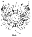
- Figure 1 shows an embodiment of a device 1 according to the invention.
- the device 1 as shown in figure 1 has a frame 3 having two parallel U-shaped frame elements 5, 7 that extend perpendicular to a longitudinal axis 9 of the frame 3.
- the U-shaped frame elements 5, 7 are spaced apart along the longitudinal axis 9 of the frame 3 in the direction of arrows A and are connected by means of a connecting beam 11.
- the frame 3 is arranged on a pipeline 13 by means of support members that are mounted on each of the U-shaped frame elements 5, 7.
- the support members include adjusting members 15, 16 and clamping members 17, 19.
- the adjusting members are mounted at one end thereof on the U-shaped frame elements 5, 7 and extend in the direction of the longitudinal axis 9 of the frame 3.
- the end of the adjusting members away from the U-shaped frame elements 5, 7 are in contact with the outer surface B of an insulating mantle 21 that surrounds the wall 23 of the pipeline 13.
- the clamping members 17, 19 are at one end thereof mounted on the U-shaped frame elements 5, 7 and are extendable in the direction of the longitudinal axis 9 of the frame 3.
- the end of the clamping members 17, 19 away from the frame 3 are, as shown in figure 1 , in contact with the outer surface of the insulating mantle 21.
- the adjusting members 15, 16 and clamping members 17, 19 are extended such that the frame 3 is arranged on the pipeline 13 with the longitudinal axis 9 of the frame 3 coinciding with the central longitudinal axis 25 of the pipeline 13.
- the clamping members 17, 19 exert in clamping force on the surface B of the insulation mantle 21 such that the frame 3 is arranged stationary relative to the pipeline 13.
- adjusting members 15, 16 and clamping members 17 and 19 are mounted on each of the U-shaped frame elements.
- the frame 3 is arrangeable on the pipeline 13 and is liftable away therefrom by means of a hoisting eye 27 that is mounted on the connecting beam 11.
- a hook 29 at the end of a chain 39 of a hoisting installation (not shown) is coupled with the hoisting eye 27.
- the device 1 is further provided with a spray nozzle support element 33 that supports a number of spray nozzles 35.
- the spray nozzle support element 33 as shown in figure 1 is ring-shaped and surrounds a section 13b of the pipeline that has no insulation mantle surrounding the wall 23 of the pipeline 13.
- the spray nozzle support element 33 extends along a full circle around the longitudinal axis 9 of the frame 3. Details of the spray nozzle support elements 33 will be described further herein below with reference to figures 3 and 4 .
- the device 1 of figure 1 is further provided with a linear motion mechanism 39 by means of which the spray nozzle support element 33 is translatable relative to the frame 3 parallel to the longitudinal axis 9 of the frame 3 in the direction of arrows A. Furthermore the device 1 is provided with a rotary motion mechanism 41 by means of which the spray nozzle support element 33 is rotatable relative to the frame 3 about the longitudinal axis 9 of the frame 3 in the direction of arrows C.
- the frame 3 is arranged on the pipeline 13 with the longitudinal axis 9 thereof coinciding with the central longitudinal axis 25 of the pipeline 13 and is arranged stationary relative to the pipeline 13, the spray nozzle support element 33 and spray nozzles 35 are translatable by means of the linear motion mechanism 39 along the central longitudinal axis 25 of the pipeline 13 in the direction of arrows A.
- the frame 3 is arranged on the pipeline 13 with the longitudinal axis 9 thereof coinciding with the central longitudinal axis 25 of the pipeline and since the frame 3 is arranged stationary relative to the pipeline 13, the spray nozzle support element 33 and spray nozzles 35 are rotatable about the central longitudinal axis 25 of the pipeline 13 in the direction of arrows C by means of the rotary motion mechanism 41. Details of the linear motion mechanism 39 and of the rotary motion mechanism 41 are shown in figure 2 .
- Figure 2 shows the device 1 of figure 1 with parts taken away to be able to show the linear motion mechanism 39 and the rotary motion mechanism 41 in more detail.
- the linear motion mechanism 39 is shown having two guiding rods 43 and 45 arranged on either side of the spray nozzle support element 33 and extending parallel to the longitudinal axis 9 of the frame 3.
- Displaceable mounted on each of the guiding rods 43, 45 is a respective carriage 47, 49 that supports the spray nozzle support element 33.
- the carriages 47, 49 are displaceable along the guiding rods 43, 45 in the direction of arrows A by means of a respective rack-and-pinion type linear actuator 51, 53.
- the respective racks 55, 57 of the rack-and-pinion type linear actuators 51, 53 are arranged parallel to the guiding rods 43 and 45 respectively on either side of the spray nozzle support element 33.
- a pinion is arranged that is driven by a respective motor 59.
- Each of the motors 59 of the respective rack-and-pinion type actuators 51, 53 is connected to a controller that is adapted for controlling the translation of the carriages 47 and 49 and the nozzle support element 43 supported by the carriages along the longitudinal axis 9 of the frame 3 in the direction of arrows A.
- the racks 45, 47, as well as the guiding rods 43, 45, are each at one end thereof mounted on a first support frame 61 and at the other end thereof mounted on a second support frame 63.
- the first support frames 61 is rotatable arranged on one of the U-shaped frame element 5, while the second support frame 63 is rotatable arranged on the other U-shaped frame element 7.
- the support frames 61, 63 are rotatable arranged on the respective U-shaped element 5, 7 by means of a plurality of guiding wheels 65 that are mounted on the U-shaped elements 5, 7.
- each of the U-shaped support frame elements 61, 63 are interconnected by means of a number of support frame connection beams 67, 69 and 71, to form a support frame that is rotatable with respect to the frame 3 about the longitudinal axis 9 of the frame 3. Also shown in figure 2 is that on each of the U-shaped frame elements 5 and 7 a chain 73, 75 is arranged that is functionally connected with a respective toothed wheel 77, 79.
- the toothed wheels 77 and 79 are each driven by a respective motor 81 and 83 such that by driving the toothed wheels 77 and 79 the toothed wheels displace along the chains 73 and 75 with the result that the support frame formed by the support frame elements 61 and 63 and the support frame connection beams 67, 69 and 71, as well as the linear motion mechanism 39 and spray nozzle support element 33 mounted thereon, rotate with respect to the frame 3 about the longitudinal axis 9 of the frame 3.
- Each of the motors 81 and 83 is connected to a controller that is configured to control the rotation of the support frame about the longitudinal axis 9 of the frame 3 relative to the frame 3.
- protective sleeves 85 are arranged around the guiding rods 43 and 45 and racks 55 and 57 to protect the guiding rods and the racks.
- each of the carriages 47 and 49 is provided with a first through hole 85, 87 through which the guiding rods 43, 45 extend when the carriages 47, 49 are mounted thereon, and a second through hole 89, 91 through which the racks 55, 57 extend to be engaged by pinions that are mounted on a output shaft of the respective motors 59a and 59b.
- the spray nozzle support element 33 extends along a full circle about the longitudinal axis 9 of the frame.
- the spray nozzle support element 33 comprises three sub elements 33a, 33b and 33c.
- Each of the spray nozzle support elements 33a, 33b and 33c extends along a part of the circle along which the spray nozzle support element 33 extends.
- Sub element 33a is mounted at each end thereof on a respective support bracket 93, 95.
- Sub element 33b is mounted at one end thereof on support bracket 93 via a hinge 97 such that sub element 33b is rotatable relative to the support bracket 93 and the sub element 33a about an axis of rotation 99 that extends parallel to the longitudinal axis 9 of the frame 3.
- Sub element 33c is at one end thereof mounted on support bracket 95 via a hinge 101 such that sub element 33c is rotatable relative to support bracket 95 about an axis of rotation 103 that extends parallel to the longitudinal axis 9 of the frame 3.
- Sub element 33b is rotatable about axis of rotation 99 by means of a piston type linear actuator 105 that is with one functional end thereof mounted on support bracket 93 and with another functional end thereof mounted to sub element 33b.
- Sub element 33c is rotatable about axis of rotation 103 by means of a piston type linear actuator 107 that is with one functional end thereof mounted on support bracket 95 and with another functional end thereof mounted on sub element 33c.
- sub elements 33b and 33c are rotatable about their respective axis of rotation 99, 103 between a closed position and an open position.
- the closed position shown in figure 3 by means of continuous lines, the respective free ends of the sub elements 33b and 33c are in contact such that sub elements 33a, 33b and 33c form a closed circle around the longitudinal axis 9 of the frame 3.
- the sub elements 33b and 33c are rotatable about their respective axis of rotation 99, 103 by means of the linear actuators 105 and 107 in the direction of arrows R, such that the respective ends of the sub elements 33b and 33c away from the ends thereof that are mounted on the support brackets 93, 95 are moved away from each other.
- the sub elements 33b and 33c are thus brought in the open position thereof, shown in figure 3 by means of striped lines, in which position an opening 109 is present in the previously closed circle.
- the spray nozzle support elements 33a, 33b, and 33c can be placed over a pipeline to be coated, after which the sub elements 33b and 33c are brought in the closed position thereof, such that the circumferential wall of the pipeline to be coated is enclosed by the spray nozzle support element 33.
- FIG 4 a perspective view is shown of sub element 33b of the spray nozzle support element 33.
- the sub element 33c comprises a spray chamber 111 that is defined by walls 113, 115, 117, 119 and 121.
- top wall 117 spray nozzles 35g to 35j are arranged.
- the side walls 113 and 121 extend from the top walls 115 and 119 towards the longitudinal axis 9 of the frame 3 when sub element 33c is in the closed position thereof.
- the side walls 113 and 121 have a free end 113a and 121a, such that the spray chamber 111 is open towards the longitudinal axis 9 of the frame 3 when sub element 33c is in the closed position thereof.
- a brush type seal member 123, 125 is arranged on the respective free ends 113a, 121a of side walls 113, 121.
- the side walls 113, 121 extend towards the outer surface of the wall of the pipeline to be coated, which outer surface is schematically shown in figure 4 by means of the surface area S enclosed by striped lines.
- the brush type seal members 123 and 125 close the gap G between the free ends 113a and 121a of the side walls 113 and 121 and the surface area S to be coated.
- the spray chamber 111 in combination with the surface area S to be coated forms a spray space.
- the spray nozzles 35g to 35j are arranged such that, with the sub element 33c in the closed position, the outlet thereof is directed towards the longitudinal axis 9 of the frame 3, such that when the sub elements 33a, 33b and 33c are arranged around the circumferential wall of a pipeline, the outlets of the spray nozzles 35g to 35j are directed towards the surface area S to be coated.
- suction elements in the form of suction holes 127 that are connectable to a suction apparatus (not shown) are arranged in top walls 115, 119.
- the suction holes 127 are partly separated from the spray nozzles 35g to 35j by means of separation walls 129 and 131 that are arranged in the spray chamber 111 between the spray nozzles and the suction holes.
- the suction holes 127 are arranged on opposite sides of the spray nozzles 35g and 35j.
- Coating material that does not adhere to the surface area S to be coated is sucked through the suction holes 127 by means of the suction apparatus connected thereto (not shown) as shown by means of the arrows D.
- the separation walls 129 and 131 avoid that coating material 133 is sucked through the suction holes 127 before being brought in contact with the surface area S to be coated.
- Sub elements 33a and 33c are configured the same way as sub element 3c that is shown in figure 4 .
- the ends 135 and 137 of the sub elements are brought into contact with the respective neighboring sub element, such that the spray chambers 111 of the respective sub elements form the spray chamber of the spray nozzle support element 33.
- the spray chamber of the spray nozzle support element 33 in combination with the surface area S to be coated forms an enclosed spray space.
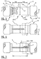
- Pipeline 13 has a wall 23, for instance made of steel.
- the pipeline 13 is formed by butt-welding the end 137a of a first length of pipe 137 to the end 139a of a second length of pipe 139 by means of a circumjacent girth-weld 141.
- Each length of pipe 137, 139 has an insulating mantle 21 with outer surface B that surrounds the wall 23 of the respective length of pipe.
- the insulating mantle 21 is for instance formed by a thermo-insulating coating made of polypropylene. Between the insulating mantle 21 and the outer surface 23a of the wall 23 of each length of pipe 137, 139 an anticorrosion coating 143 is arranged.
- each length of pipe 137, 139 is at the respective end 137a, 139a thereof uncoated along a certain part L137, L139 of the length of pipe 137, 139, such that a so-called cut back results.
- the uncoated ends 137a, 139a form a gap 145 in the insulating mantle 21 and the anticorrosion coating 143 of the resulting pipeline 13.
- the uncoated surface area S of the outer surface 23a of the wall 23 is heated, for instance in case of a steel wall by heating the wall 23 by means of induction heating.
- coating material in the form of powder is applied to the heated surface area S to be coated by means of the device 1 according to the invention as shown in figures 1 to 4 .
- the frame 3 of the device 1 according to the invention is arranged stationary relative to the pipeline 13, and the spray nozzle support element 33 is arranged around the circumferential wall 23 of the pipeline 13. The result of the step is shown in figure 1 .
- coating forming material 133 in the form of powder is forced through the spray nozzle 35 arranged on the spray nozzle support element 33. As shown in figure 4 and figure 5 this results in coating forming material 133 to be applied on the surface area S as to be coated in a spray area P for each spray nozzle 35. For clarity reasons, only one spray area P of one of the spray nozzles is shown in figure 6 and 7 during the displacement of the spray nozzle support element 33 and the spray nozzles arranged thereon.
- the spray nozzle support element While forcing the coating forming material 133 through the spray nozzles, the spray nozzle support element is displaced relative to the frame 3 such that the spray nozzles are translated in a first direction E parallel to the longitudinal axis 25 of the pipeline 13 by displacing said spray nozzle support element 33 along the guiding rods 43, 45 parallel to the longitudinal axis 9 of the frame 3 that coincides with the longitudinal axis 25 of the pipeline as is shown in figure 6 .
- the spray nozzle support element 33 is displaced relative to the frame 3 such that the spray nozzles are rotated about said central longitudinal axis 25 of said pipeline 13 in the direction F and the spray nozzle support element 33 is translated in the direction H opposite to the first direction E along the length L of said surface area S to be coated, such that the coating material applied on the surface area S while displacing the spray nozzle support element in the direction of arrow H partly overlaps the coating material that was applied while displacing the spray nozzle support element 33 in the direction of arrow E during the previous step.
- the spray nozzles are rotated about said central longitudinal axis 25 of said pipeline 13 in the direction F over half the distance between adjacent spray nozzles along the circle about said longitudinal axis of the pipeline along which circle the spray nozzle support element extends.
- the coating material in the form of powder applied to the heated surface area S to be coated is heated by heat transferred from the wall 23 to said coating material such that an anti-corrosion coating applied to the surface area S results.
- This process of applying and heating powder as a coating material to form a coating is a so-called powder coating process.
- the translation of the spray nozzle support element 33 starts at a start position and ends at an end position such that the coating material applied to the surface area S to be coated partly overlaps the anti-corrosion coating 143 that was already arranged on the wall 23 of the lengths of pipe 137, 139, such that a continuous anticorrosion coating results.
- This can be easily achieved because of the single row configuration of the spray nozzles.
- the whole surface area S to be coated can be more uniformly coated by translating the spray nozzle support element one time in the direction of arrow E and one time in the direction of arrow H.
- the spray nozzle support element 33 is rotated back and forth about the longitudinal axis 25 of the pipeline 13 in an oscillating motion while translating the spray nozzle support element 33 in the first direction E along the length L of said surface area S to be coated. In that case the same result of a more uniformly coated surface area S can be achieved while translating the spray nozzle support element 33 only in one direction, i.e. the first direction E.
Landscapes
- Engineering & Computer Science (AREA)
- General Engineering & Computer Science (AREA)
- Mechanical Engineering (AREA)
- Spray Control Apparatus (AREA)
- Application Of Or Painting With Fluid Materials (AREA)
- Nozzles (AREA)
Claims (18)
- Vorrichtung (1) zum Beschichten eines Oberflächenbereichs einer Lücke in der Beschichtung einer Pipeline (13), wobei der Oberflächenbereich eine Länge entlang der zentralen Längsachse der Pipeline aufweist und eine Breite von wenigstens einem Teil des Umfangs der Pipeline, wobei die Vorrichtung umfasst:- ein Gestell (3);- ein Sprühdüsen-Lagerungselement (33), das eine Anzahl von Sprühdüsen (35) hält;- einen Linearbewegungsmechanismus (39), der ausgelegt ist zum Versetzen des Sprühdüsen-Lagerungselements (33) relativ zu dem Gestell und parallel zu einer Längsachse des Gestells (9); und- Lagerungselemente, die ausgelegt sind für ein Anordnen des Gestells stationär relativ zu der Pipeline, wobei die Längsachse des Gestells mit der zentralen Längsachse der Pipeline übereinstimmt;so dass über ein Versetzen des Sprühdüsen-Lagerungselements relativ zu dem Gestell mittels des Linearbewegungsmechanismus die Sprühdüsen entlang der Länge des Oberflächenbereichs mit den auf den Oberflächenbereich gerichteten Sprühdüsen versetzbar sind;
wobei die Vorrichtung weiter umfasst:- einen Drehbewegungsmechanismus (41), der ausgelegt ist zum Drehen des Sprühdüsen-Lagerungselements relativ zu dem Gestell um die Längsachse des Gestells;
so dass über ein Drehen des Sprühdüsen-Lagerungselements relativ zu dem Gestell um die Längsachse des Gestells die Sprühdüsen entlang der Breite des Oberflächenbereichs versetzbar sind;
wobei- sich das Sprühdüsen-Lagerungselement entlang eines vollen Kreises um die Längsachse des Gestells erstreckt und eine Vielzahl von Sprühdüsen entlang des vollen Kreises verteilt ist; und
wobei- die Sprühdüsen als Konus-Sprühdüsen vorgesehen sind und derart angeordnet sind, dass im Betrieb aneinander angrenzende Sprüh-Kegel (135) teilweise überlappen. - Vorrichtung gemäß Anspruch 1,- derart ausgelegt, dass der Linearbewegungsmechanismus und der Drehbewegungsmechanismus in Reihe angeordnet sind und separate Antriebe aufweisen.
- Vorrichtung gemäß Anspruch 1 oder 2, bei der- die Vielzahl von Sprühdüsen in gleichen Abständen entlang wenigstens eines Teils eines Kreises verteilt ist.
- Vorrichtung gemäß Anspruch 1, 2 oder 3, bei der- das Sprühdüsen-Lagerungselement eine Vielzahl von Unterelementen umfasst, von denen sich jedes entlang eines Teils des Kreises um die Längsachse des Gestells erstreckt, wobei die Unterelemente über Scharniere miteinander verbunden sind, so dass die Unterelemente relativ zueinander drehbar vorgesehen sind, um das Sprühdüsen-Lagerungselement um den Umfang der Pipeline anordnen zu können;
wobei vorzugsweise die Vorrichtung weiter umfasst- eine Anzahl von Betätigungselementen zum Drehen der Unterelemente relativ zueinander. - Vorrichtung gemäß einem der Ansprüche 1 bis 4, bei der- das Sprühdüsen-Lagerungselement eine Sprühkammer umfasst, die über eine Anzahl von Wänden definiert ist, wobei die Kammer zu der Längsachse des Gestells offen ist und wobei in der Sprühkammer die Sprühdüsen angeordnet sind; und
wobei- die Sprühkammer ausgelegt ist, um sich von den Sprühdüsen zu der Längsachse des Gestells derart zu erstrecken, dass die Sprühkammer zusammen mit dem zu beschichtenden Oberflächenbereich einen Sprühraum einfasst. - Vorrichtung gemäß Anspruch 5, bei der das Sprühdüsen-Lagerungselement weiter ein Dichtelement umfasst, das an einem Ende der Sprühkammer entfernt von den Sprühdüsen angeordnet ist und ausgelegt ist, um eine Lücke zwischen der Sprühkammer und dem zu beschichtenden Oberflächenbereich zu schließen.
- Vorrichtung gemäß Anspruch 5 oder 6,
weiter umfassend- eine Anzahl von Saugelementen, die in der Sprühkammer angeordnet sind und mit einer Saugvorrichtung verbindbar sind. - Vorrichtung gemäß Anspruch 7, bei der das Sprühdüsen-Lagerungselement eine Anzahl von Trennwänden umfasst, die in der Sprühkammer zwischen den Saugelementen und den Sprühdüsen angeordnet sind, und ausgelegt sind, für ein teilweises Abtrennen der Saugelemente von den Sprühdüsen.
- Vorrichtung gemäß Anspruch 7 oder 8, bei der die Saugelemente an gegenüberliegenden Seiten von den Sprühdüsen angeordnet sind.
- Vorrichtung gemäß einem der Ansprüche 1 bis 9, bei der- die Vorrichtung einen Ausgabe-Anpassmechanismus umfasst, der ausgelegt ist für ein Anpassen der Ausgaberate eines Beschichtungsmaterials, das von jeder der Sprühdüsen aufgesprüht wird, wobei vorzugsweise jede der Sprühdüsen einen Anpassmechanismus umfasst, der ausgelegt ist, um die Ausgaberate davon anzupassen.
- Vorrichtung gemäß einem der Ansprüche 1 bis 10, bei der die Lagerungselemente Anpasselemente umfassen, die ausgelegt sind für ein Anpassen der Position der Längsachse des Gestells relativ zu der zentralen Längsachse der Pipeline.
- Vorrichtung gemäß einem der Ansprüche 1 bis 11, bei der die Lagerungselemente angeordnet sind, um das Gestell an einem beschichteten Oberflächenbereich der Pipeline zu halten.
- Vorrichtung gemäß einem der Ansprüche 1 bis 12, bei der die Lagerungselemente Klemmelemente umfassen, die ausgelegt sind für ein Klemmen des Gestells an der Pipeline, so dass das Gestell relativ zu der Pipeline stationär vorgesehen ist.
- Vorrichtung gemäß einem der Ansprüche 1 bis 13, bei der das Gestell zwei parallele U-förmige Gestell-Elemente umfasst, die sich senkrecht zu der Längsachse des Gestells erstrecken und entlang der Längsachse des Gestells voneinander beabstandet sind, wobei die Lagerungselemente an den U-förmigen Gestell-Elementen angeordnet sind, und wobei der Linearbewegungsmechanismus derart angeordnet ist, dass das Sprühdüsen-Lagerungselement zwischen den U-förmigen Gestell-Elementen umsetzbar ist.
- Verfahren zum Beschichten eines Oberflächenbereichs einer beschichteten Pipeline (13), wobei der Oberflächenbereich eine Länge entlang der zentralen Längsachse der Pipeline (9) aufweist und eine Breite von wenigstens einem Teil des Umfangs der Pipeline, wobei das Verfahren die Schritte umfasst:(a) Stationäres Anordnen eines Gestells (3) relativ zu der Pipeline mit einem daran befestigten versetzbaren Sprühdüsen-Lagerungselement (33), das daran eine Anzahl von Sprühdüsen (35) aufweist, wobei das Sprühdüsen-Lagerungselement sich entlang eines vollen Kreises um die zentrale Längsachse des Gestells erstreckt und eine Vielzahl von Sprühdüsen entlang des vollen Kreises verteilt ist, und wobei die Sprühdüsen als Konus-Sprühdüsen vorgesehen sind und derart angeordnet sind, dass in Betrieb einander angrenzende Sprühkegel (135) teilweise überlappen;(b) Durchtreiben eines Beschichtungs-Bildungsmaterials durch die Sprühdüsen während das Sprühdüsen-Lagerungselement relativ zu dem Gestell versetzt wird, so dass- die Sprühdüsen in einer ersten Richtung parallel zu der Längsachse der Pipeline entlang der Länge des Oberflächenbereichs versetzt werden, und- das Beschichtungs-Bildungsmaterial auf den Oberflächenbereich aufgetragen wird,
wobei das Verfahren weiter umfasst nach Schritt (b), die Schritte von(c) Versetzen des Sprühdüsen-Lagerungselements relativ zu dem Gestell, so dass die Sprühdüsen um die Längsachse der Pipeline gedreht werden; und nachfolgend(d) Durchtreiben des Beschichtungs-Bildungsmaterials durch die Sprühdüsen während das Sprühdüsen-Lagerungselement relativ zu dem Gestell versetzt wird, so dass- die Sprühdüsen in die Richtung gegenüberliegend zu der ersten Richtung entlang der Länge des Oberflächenbereichs versetzt werden; und- das Beschichtungs-Bildungsmaterial auf den Oberflächenbereich aufgetragen wird;wobei
Schritte (c) und (d) derart ausgeführt werden, dass das Beschichtungsmaterial das über eine Sprühdüse auf den Oberflächenbereich in Schritt (d) aufgetragen wird, teilweise das Beschichtungsmaterial, das über die Sprühdüse auf dem Oberflächenbereich in Schritt (b) aufgetragen wird, überlappt. - Verfahren zum Beschichten eines Oberflächenbereichs einer beschichteten Pipeline (13), wobei der Oberflächenbereich eine Länge entlang der zentralen Längsachse der Pipeline (9) aufweist und eine Breite von wenigstens einem Teil des Umfangs der Pipeline, wobei das Verfahren die Schritte umfasst:(a) Anordnen eines Gestells (3) stationär relativ zu der Pipeline, wobei das Gestell ein Sprühdüsen-Lagerungselement (33) versetzbar daran befestigt hat, wobei das Sprühdüsen-Lagerungselement (33) daran eine Vielzahl von Sprühdüsen (35) angeordnet hat, wobei das Sprühdüsen-Lagerungselement sich entlang eines vollen Kreises um die zentrale Längsachse des Gestells erstreckt und eine Vielzahl von Sprühdüsen entlang des vollen Kreises verteilt ist, und wobei die Sprühdüsen als Konus-Sprühdüsen vorgesehen sind und derart angeordnet sind, dass aneinander angrenzende Sprüh-Kegel (135) teilweise überlappen;(b) Durchtreiben eines Beschichtungsmaterials durch die Sprühdüsen, während das Sprühdüsen-Lagerungselement relativ zu dem Gestell versetzt wird, so dass- die Sprühdüsen in eine erste Richtung parallel zu der Längsachse der Pipeline entlang der Länge des Oberflächenbereichs versetzt werden, und- das Beschichtungs-Bildungsmaterial auf den Oberflächenbereich aufgetragen wird;wobei das Verfahren weiter umfasst während Schritt b- Versetzen des Sprühdüsen-Lagerungselements relativ zu dem Gestell, so dass die Sprühdüsen um die Längsachse hin- und her gedreht werden, um die Längsachse der Pipeline in einer sich hin- und herbewegenden Bewegung, während die Sprühdüsen in die erste Richtung parallel zu der Längsachse der Pipeline versetzt werden.
- Verfahren gemäß Anspruch 15 oder 16,
bei dem- das Sprühdüsen-Lagerungselement sich entlang wenigstens eines Teils eines Kreis um die Längsachse der Pipeline erstreckt, eine Vielzahl von Sprühdüsen in gleichen Abständen entlang des wenigstens einen Teils des Kreises verteilt ist, und der Versatz des Sprühdüsen-Lagerungselements relativ zu dem Gestell derart vorgesehen ist, dass die Sprühdüsen um die Längsachse der Rohrleitung gedreht werden, der Hälfte der Entfernung zwischen aneinander angrenzenden Sprühdüsen entlang des wenigstens einen Teils eines Kreis entspricht. - Verfahren gemäß einem der Ansprüche 15 bis 17, weiter umfassend den Schritt:- Anpassen der Ausgaberate von jeder der Sprühdüsen, so dass die Variation bei dem Einfluss der Erdanziehungskraft auf das Beschichtungs-Bildungsmaterial als Folge von unterschiedlichen Positionen der Sprühdüsen kompensiert wird.
Applications Claiming Priority (2)
| Application Number | Priority Date | Filing Date | Title |
|---|---|---|---|
| NL2008206A NL2008206C2 (en) | 2012-01-31 | 2012-01-31 | Device and method for the coating of a surface area of a gap in the coating of a pipeline. |
| PCT/NL2013/050052 WO2013115646A1 (en) | 2012-01-31 | 2013-01-31 | Device and method for the coating of a surface area of a gap in the coating of a pipeline |
Publications (2)
| Publication Number | Publication Date |
|---|---|
| EP2809451A1 EP2809451A1 (de) | 2014-12-10 |
| EP2809451B1 true EP2809451B1 (de) | 2016-09-14 |
Family
ID=47739459
Family Applications (1)
| Application Number | Title | Priority Date | Filing Date |
|---|---|---|---|
| EP13705029.0A Active EP2809451B1 (de) | 2012-01-31 | 2013-01-31 | Vorrichtung und verfahren zur beschichtung eines oberflächenbereichs in der lücke einer beschichtung einer rohrleitung |
Country Status (10)
| Country | Link |
|---|---|
| US (1) | US10184590B2 (de) |
| EP (1) | EP2809451B1 (de) |
| AU (1) | AU2013215694B2 (de) |
| BR (1) | BR112014016051B8 (de) |
| CA (1) | CA2861229C (de) |
| DK (1) | DK2809451T3 (de) |
| NL (1) | NL2008206C2 (de) |
| RU (1) | RU2618711C2 (de) |
| SG (1) | SG11201403231TA (de) |
| WO (1) | WO2013115646A1 (de) |
Families Citing this family (16)
| Publication number | Priority date | Publication date | Assignee | Title |
|---|---|---|---|---|
| ITMI20132004A1 (it) * | 2013-11-29 | 2015-05-30 | Saipem Spa | Apparecchiatura, stazione di lavoro e metodo per applicare un foglio protettivo di materiale polimerico a una tubazione e programma per elaboratore per attuare il metodo |
| AU2015201875B2 (en) * | 2015-04-14 | 2020-10-01 | Field Joint Coatings Pty Ltd | Pipe spray machine |
| CN104888998B (zh) * | 2015-06-02 | 2016-04-20 | 中国石油集团工程技术研究院 | 一种调节装置 |
| ITUB20152638A1 (it) | 2015-07-30 | 2017-01-30 | Saipem Spa | Apparecchiatura e metodo per rivestire tubazioni |
| GB201708326D0 (en) * | 2017-05-24 | 2017-07-05 | Kongsberg Ferrotech As | Maintenance and repair device |
| CN108970900A (zh) * | 2018-07-12 | 2018-12-11 | 安徽贵达汽车部件有限公司 | 一种刹车蹄铁自动化喷胶装置 |
| CN108906374A (zh) * | 2018-08-02 | 2018-11-30 | 繁昌县长城铸造厂(普通合伙) | 一种用于金属管外表面涂层的涂料喷涂系统 |
| WO2020097354A2 (en) * | 2018-11-09 | 2020-05-14 | Illinois Tool Works Inc. | Modular fluid application device for varying fluid coat weight |
| GB2581469A (en) * | 2018-11-16 | 2020-08-26 | Pipeline Technique Ltd | Tape winding apparatus and method |
| CN110773355A (zh) * | 2019-11-05 | 2020-02-11 | 湖南城市学院 | 一种变压器生产用表面喷粉设备 |
| CN111760734B (zh) * | 2020-07-07 | 2021-12-17 | 周鹏 | 一种带有防碰撞机构的钢筋生产用涂层喷涂装置及方法 |
| CN112317171B (zh) * | 2020-10-19 | 2022-02-18 | 滁州市新华建筑安装有限责任公司 | 一种适应性强的建筑工程装修用多面体板材喷漆机构 |
| CN112547418A (zh) * | 2020-11-24 | 2021-03-26 | 温州足矣电子商务有限公司 | 一种能适应各类不同圆柱形物品进行均匀涂胶的环保装置 |
| CN112871503B (zh) * | 2021-01-12 | 2022-12-06 | 泰州远大家俬有限公司 | 一种角钢多角度自动喷涂设备及其方法 |
| CN114160338B (zh) * | 2021-11-15 | 2023-03-31 | 佛山综合能源(公控)有限公司 | 一种保温管接口处的防腐处理喷涂装置 |
| CN119456274A (zh) * | 2025-01-14 | 2025-02-18 | 兰州石化职业技术大学 | 一种油库管道外防腐层涂料装置 |
Family Cites Families (8)
| Publication number | Priority date | Publication date | Assignee | Title |
|---|---|---|---|---|
| US4007705A (en) * | 1974-12-20 | 1977-02-15 | Dnd Corporation | Apparatus for treating a cylindrical object |
| IE47522B1 (en) * | 1977-07-16 | 1984-04-18 | Walton Mole Co | Apparatus for cleaining and descaling the exterior of elongate cylindrical structures such as pipe lines and jackets of off-shore oil rigs |
| SU654301A1 (ru) * | 1977-10-13 | 1979-03-30 | Филиал N1 Специализированного Проектно-Конструкторского Технологического Бюро Научно-Производственного Объединения "Научплитпром" | Устройство дл двухстороннего нанесени покрыти на издели |
| NL8203501A (nl) * | 1982-09-08 | 1984-04-02 | Dirk Frans Van Voskuilen En Fr | Werkwijze en inrichting voor het debitumineren of verwijderen van een ander-soortige bekleding, zoals een bekleding van polyethyleen, van een buis. |
| CA2097091C (en) * | 1992-07-10 | 2000-10-31 | Sidney A. Taylor | High pressure water jet cleaner and coating applicator |
| FR2723006B1 (fr) * | 1994-07-28 | 1996-09-13 | Gts Isopipe Sa | Procede pour realiser un revetement de protection sur un tube et, notamment, sur un tube de pipeline dispositif et installation pour sa mise en oeuvre |
| US6881266B1 (en) * | 1999-10-30 | 2005-04-19 | Pipeline Induction Heat Ltd. | Apparatus and method for coating pipes |
| GB0907859D0 (en) * | 2009-05-07 | 2009-06-24 | Saipem Spa | Apparatus and method for heating heat-shrinkable pipe sleeves |
-
2012
- 2012-01-31 NL NL2008206A patent/NL2008206C2/en active
-
2013
- 2013-01-31 CA CA2861229A patent/CA2861229C/en active Active
- 2013-01-31 RU RU2014135396A patent/RU2618711C2/ru active
- 2013-01-31 US US14/375,951 patent/US10184590B2/en active Active
- 2013-01-31 EP EP13705029.0A patent/EP2809451B1/de active Active
- 2013-01-31 DK DK13705029.0T patent/DK2809451T3/en active
- 2013-01-31 AU AU2013215694A patent/AU2013215694B2/en active Active
- 2013-01-31 BR BR112014016051A patent/BR112014016051B8/pt active IP Right Grant
- 2013-01-31 WO PCT/NL2013/050052 patent/WO2013115646A1/en not_active Ceased
- 2013-01-31 SG SG11201403231TA patent/SG11201403231TA/en unknown
Also Published As
| Publication number | Publication date |
|---|---|
| BR112014016051A2 (pt) | 2017-06-13 |
| NL2008206C2 (en) | 2013-08-01 |
| AU2013215694B2 (en) | 2017-04-13 |
| BR112014016051A8 (pt) | 2017-07-04 |
| CA2861229C (en) | 2020-10-27 |
| SG11201403231TA (en) | 2014-08-28 |
| RU2618711C2 (ru) | 2017-05-11 |
| BR112014016051B1 (pt) | 2020-12-29 |
| AU2013215694A1 (en) | 2014-07-10 |
| US20140370200A1 (en) | 2014-12-18 |
| RU2014135396A (ru) | 2016-03-27 |
| EP2809451A1 (de) | 2014-12-10 |
| BR112014016051B8 (pt) | 2021-08-03 |
| US10184590B2 (en) | 2019-01-22 |
| WO2013115646A1 (en) | 2013-08-08 |
| CA2861229A1 (en) | 2013-08-08 |
| DK2809451T3 (en) | 2017-01-09 |
Similar Documents
| Publication | Publication Date | Title |
|---|---|---|
| EP2809451B1 (de) | Vorrichtung und verfahren zur beschichtung eines oberflächenbereichs in der lücke einer beschichtung einer rohrleitung | |
| EP2197592B1 (de) | Vorrichtung zur beschichtung von rohren | |
| AU2020294342B2 (en) | Pipe spray machine | |
| WO2018097718A1 (en) | Method of installing a protective coating | |
| JP2015524923A (ja) | ロボットを使用する、核施設のプールにおけるクラックのシーリング | |
| US10688517B2 (en) | Apparatus and method for coating pipelines | |
| JP6092570B2 (ja) | 鋼棒の被膜形成方法と、被膜形成鋼棒の生産方法 | |
| EP3074687B1 (de) | Vorrichtung und verfahren zum aufbringen einer schutzfolie aus einem polymerstoff auf eine rohrleitung | |
| WO2015064047A1 (ja) | 金属管の曲げ加工装置、蛇行管の製造方法及び蛇行管 | |
| JP6346324B2 (ja) | 被膜形成鋼棒の生産方法 | |
| CN220763565U (zh) | 一种管道热缩防腐层加工装置 | |
| RU2285196C1 (ru) | Установка для нанесения антикоррозионной изоляции на поверхности стальной трубы | |
| SU885349A1 (ru) | Агрегат дл поточного эмалировани труб | |
| SU1078184A1 (ru) | Установка дл нанесени покрыти на поверхность трубопровода | |
| NL2007441C2 (en) | Coating device for coating a pipeline or a pipe section. |
Legal Events
| Date | Code | Title | Description |
|---|---|---|---|
| PUAI | Public reference made under article 153(3) epc to a published international application that has entered the european phase |
Free format text: ORIGINAL CODE: 0009012 |
|
| 17P | Request for examination filed |
Effective date: 20140806 |
|
| AK | Designated contracting states |
Kind code of ref document: A1 Designated state(s): AL AT BE BG CH CY CZ DE DK EE ES FI FR GB GR HR HU IE IS IT LI LT LU LV MC MK MT NL NO PL PT RO RS SE SI SK SM TR |
|
| AX | Request for extension of the european patent |
Extension state: BA ME |
|
| DAX | Request for extension of the european patent (deleted) | ||
| GRAP | Despatch of communication of intention to grant a patent |
Free format text: ORIGINAL CODE: EPIDOSNIGR1 |
|
| INTG | Intention to grant announced |
Effective date: 20151013 |
|
| GRAP | Despatch of communication of intention to grant a patent |
Free format text: ORIGINAL CODE: EPIDOSNIGR1 |
|
| INTG | Intention to grant announced |
Effective date: 20160405 |
|
| GRAS | Grant fee paid |
Free format text: ORIGINAL CODE: EPIDOSNIGR3 |
|
| GRAA | (expected) grant |
Free format text: ORIGINAL CODE: 0009210 |
|
| AK | Designated contracting states |
Kind code of ref document: B1 Designated state(s): AL AT BE BG CH CY CZ DE DK EE ES FI FR GB GR HR HU IE IS IT LI LT LU LV MC MK MT NL NO PL PT RO RS SE SI SK SM TR |
|
| REG | Reference to a national code |
Ref country code: GB Ref legal event code: FG4D |
|
| REG | Reference to a national code |
Ref country code: CH Ref legal event code: EP |
|
| REG | Reference to a national code |
Ref country code: IE Ref legal event code: FG4D |
|
| REG | Reference to a national code |
Ref country code: AT Ref legal event code: REF Ref document number: 828344 Country of ref document: AT Kind code of ref document: T Effective date: 20161015 |
|
| REG | Reference to a national code |
Ref country code: DE Ref legal event code: R096 Ref document number: 602013011475 Country of ref document: DE |
|
| REG | Reference to a national code |
Ref country code: NL Ref legal event code: FP |
|
| REG | Reference to a national code |
Ref country code: NO Ref legal event code: T2 Effective date: 20160914 |
|
| REG | Reference to a national code |
Ref country code: DK Ref legal event code: T3 Effective date: 20170104 |
|
| REG | Reference to a national code |
Ref country code: LT Ref legal event code: MG4D |
|
| PG25 | Lapsed in a contracting state [announced via postgrant information from national office to epo] |
Ref country code: FI Free format text: LAPSE BECAUSE OF FAILURE TO SUBMIT A TRANSLATION OF THE DESCRIPTION OR TO PAY THE FEE WITHIN THE PRESCRIBED TIME-LIMIT Effective date: 20160914 Ref country code: HR Free format text: LAPSE BECAUSE OF FAILURE TO SUBMIT A TRANSLATION OF THE DESCRIPTION OR TO PAY THE FEE WITHIN THE PRESCRIBED TIME-LIMIT Effective date: 20160914 Ref country code: RS Free format text: LAPSE BECAUSE OF FAILURE TO SUBMIT A TRANSLATION OF THE DESCRIPTION OR TO PAY THE FEE WITHIN THE PRESCRIBED TIME-LIMIT Effective date: 20160914 Ref country code: LT Free format text: LAPSE BECAUSE OF FAILURE TO SUBMIT A TRANSLATION OF THE DESCRIPTION OR TO PAY THE FEE WITHIN THE PRESCRIBED TIME-LIMIT Effective date: 20160914 |
|
| REG | Reference to a national code |
Ref country code: AT Ref legal event code: MK05 Ref document number: 828344 Country of ref document: AT Kind code of ref document: T Effective date: 20160914 |
|
| PG25 | Lapsed in a contracting state [announced via postgrant information from national office to epo] |
Ref country code: SE Free format text: LAPSE BECAUSE OF FAILURE TO SUBMIT A TRANSLATION OF THE DESCRIPTION OR TO PAY THE FEE WITHIN THE PRESCRIBED TIME-LIMIT Effective date: 20160914 Ref country code: LV Free format text: LAPSE BECAUSE OF FAILURE TO SUBMIT A TRANSLATION OF THE DESCRIPTION OR TO PAY THE FEE WITHIN THE PRESCRIBED TIME-LIMIT Effective date: 20160914 Ref country code: GR Free format text: LAPSE BECAUSE OF FAILURE TO SUBMIT A TRANSLATION OF THE DESCRIPTION OR TO PAY THE FEE WITHIN THE PRESCRIBED TIME-LIMIT Effective date: 20161215 |
|
| PG25 | Lapsed in a contracting state [announced via postgrant information from national office to epo] |
Ref country code: RO Free format text: LAPSE BECAUSE OF FAILURE TO SUBMIT A TRANSLATION OF THE DESCRIPTION OR TO PAY THE FEE WITHIN THE PRESCRIBED TIME-LIMIT Effective date: 20160914 Ref country code: EE Free format text: LAPSE BECAUSE OF FAILURE TO SUBMIT A TRANSLATION OF THE DESCRIPTION OR TO PAY THE FEE WITHIN THE PRESCRIBED TIME-LIMIT Effective date: 20160914 |
|
| PG25 | Lapsed in a contracting state [announced via postgrant information from national office to epo] |
Ref country code: PT Free format text: LAPSE BECAUSE OF FAILURE TO SUBMIT A TRANSLATION OF THE DESCRIPTION OR TO PAY THE FEE WITHIN THE PRESCRIBED TIME-LIMIT Effective date: 20170116 Ref country code: AT Free format text: LAPSE BECAUSE OF FAILURE TO SUBMIT A TRANSLATION OF THE DESCRIPTION OR TO PAY THE FEE WITHIN THE PRESCRIBED TIME-LIMIT Effective date: 20160914 Ref country code: SM Free format text: LAPSE BECAUSE OF FAILURE TO SUBMIT A TRANSLATION OF THE DESCRIPTION OR TO PAY THE FEE WITHIN THE PRESCRIBED TIME-LIMIT Effective date: 20160914 Ref country code: PL Free format text: LAPSE BECAUSE OF FAILURE TO SUBMIT A TRANSLATION OF THE DESCRIPTION OR TO PAY THE FEE WITHIN THE PRESCRIBED TIME-LIMIT Effective date: 20160914 Ref country code: BG Free format text: LAPSE BECAUSE OF FAILURE TO SUBMIT A TRANSLATION OF THE DESCRIPTION OR TO PAY THE FEE WITHIN THE PRESCRIBED TIME-LIMIT Effective date: 20161214 Ref country code: IS Free format text: LAPSE BECAUSE OF FAILURE TO SUBMIT A TRANSLATION OF THE DESCRIPTION OR TO PAY THE FEE WITHIN THE PRESCRIBED TIME-LIMIT Effective date: 20170114 Ref country code: CZ Free format text: LAPSE BECAUSE OF FAILURE TO SUBMIT A TRANSLATION OF THE DESCRIPTION OR TO PAY THE FEE WITHIN THE PRESCRIBED TIME-LIMIT Effective date: 20160914 Ref country code: SK Free format text: LAPSE BECAUSE OF FAILURE TO SUBMIT A TRANSLATION OF THE DESCRIPTION OR TO PAY THE FEE WITHIN THE PRESCRIBED TIME-LIMIT Effective date: 20160914 Ref country code: ES Free format text: LAPSE BECAUSE OF FAILURE TO SUBMIT A TRANSLATION OF THE DESCRIPTION OR TO PAY THE FEE WITHIN THE PRESCRIBED TIME-LIMIT Effective date: 20160914 Ref country code: BE Free format text: LAPSE BECAUSE OF FAILURE TO SUBMIT A TRANSLATION OF THE DESCRIPTION OR TO PAY THE FEE WITHIN THE PRESCRIBED TIME-LIMIT Effective date: 20160914 |
|
| REG | Reference to a national code |
Ref country code: DE Ref legal event code: R097 Ref document number: 602013011475 Country of ref document: DE |
|
| PLBE | No opposition filed within time limit |
Free format text: ORIGINAL CODE: 0009261 |
|
| STAA | Information on the status of an ep patent application or granted ep patent |
Free format text: STATUS: NO OPPOSITION FILED WITHIN TIME LIMIT |
|
| 26N | No opposition filed |
Effective date: 20170615 |
|
| REG | Reference to a national code |
Ref country code: CH Ref legal event code: PL |
|
| PG25 | Lapsed in a contracting state [announced via postgrant information from national office to epo] |
Ref country code: MC Free format text: LAPSE BECAUSE OF FAILURE TO SUBMIT A TRANSLATION OF THE DESCRIPTION OR TO PAY THE FEE WITHIN THE PRESCRIBED TIME-LIMIT Effective date: 20160914 |
|
| REG | Reference to a national code |
Ref country code: FR Ref legal event code: ST Effective date: 20170929 |
|
| PG25 | Lapsed in a contracting state [announced via postgrant information from national office to epo] |
Ref country code: FR Free format text: LAPSE BECAUSE OF NON-PAYMENT OF DUE FEES Effective date: 20170131 Ref country code: LI Free format text: LAPSE BECAUSE OF NON-PAYMENT OF DUE FEES Effective date: 20170131 Ref country code: CH Free format text: LAPSE BECAUSE OF NON-PAYMENT OF DUE FEES Effective date: 20170131 |
|
| REG | Reference to a national code |
Ref country code: IE Ref legal event code: MM4A |
|
| PG25 | Lapsed in a contracting state [announced via postgrant information from national office to epo] |
Ref country code: SI Free format text: LAPSE BECAUSE OF FAILURE TO SUBMIT A TRANSLATION OF THE DESCRIPTION OR TO PAY THE FEE WITHIN THE PRESCRIBED TIME-LIMIT Effective date: 20160914 Ref country code: LU Free format text: LAPSE BECAUSE OF NON-PAYMENT OF DUE FEES Effective date: 20170131 |
|
| PG25 | Lapsed in a contracting state [announced via postgrant information from national office to epo] |
Ref country code: IE Free format text: LAPSE BECAUSE OF NON-PAYMENT OF DUE FEES Effective date: 20170131 |
|
| PG25 | Lapsed in a contracting state [announced via postgrant information from national office to epo] |
Ref country code: MT Free format text: LAPSE BECAUSE OF NON-PAYMENT OF DUE FEES Effective date: 20170131 |
|
| PG25 | Lapsed in a contracting state [announced via postgrant information from national office to epo] |
Ref country code: AL Free format text: LAPSE BECAUSE OF FAILURE TO SUBMIT A TRANSLATION OF THE DESCRIPTION OR TO PAY THE FEE WITHIN THE PRESCRIBED TIME-LIMIT Effective date: 20160914 |
|
| PG25 | Lapsed in a contracting state [announced via postgrant information from national office to epo] |
Ref country code: HU Free format text: LAPSE BECAUSE OF FAILURE TO SUBMIT A TRANSLATION OF THE DESCRIPTION OR TO PAY THE FEE WITHIN THE PRESCRIBED TIME-LIMIT; INVALID AB INITIO Effective date: 20130131 |
|
| PG25 | Lapsed in a contracting state [announced via postgrant information from national office to epo] |
Ref country code: CY Free format text: LAPSE BECAUSE OF FAILURE TO SUBMIT A TRANSLATION OF THE DESCRIPTION OR TO PAY THE FEE WITHIN THE PRESCRIBED TIME-LIMIT Effective date: 20160914 |
|
| PG25 | Lapsed in a contracting state [announced via postgrant information from national office to epo] |
Ref country code: MK Free format text: LAPSE BECAUSE OF FAILURE TO SUBMIT A TRANSLATION OF THE DESCRIPTION OR TO PAY THE FEE WITHIN THE PRESCRIBED TIME-LIMIT Effective date: 20160914 |
|
| PG25 | Lapsed in a contracting state [announced via postgrant information from national office to epo] |
Ref country code: TR Free format text: LAPSE BECAUSE OF FAILURE TO SUBMIT A TRANSLATION OF THE DESCRIPTION OR TO PAY THE FEE WITHIN THE PRESCRIBED TIME-LIMIT Effective date: 20160914 |
|
| P01 | Opt-out of the competence of the unified patent court (upc) registered |
Effective date: 20230515 |
|
| PGFP | Annual fee paid to national office [announced via postgrant information from national office to epo] |
Ref country code: DE Payment date: 20250129 Year of fee payment: 13 |
|
| PGFP | Annual fee paid to national office [announced via postgrant information from national office to epo] |
Ref country code: DK Payment date: 20250127 Year of fee payment: 13 |
|
| PGFP | Annual fee paid to national office [announced via postgrant information from national office to epo] |
Ref country code: NO Payment date: 20250129 Year of fee payment: 13 |
|
| PGFP | Annual fee paid to national office [announced via postgrant information from national office to epo] |
Ref country code: IT Payment date: 20250121 Year of fee payment: 13 Ref country code: GB Payment date: 20250127 Year of fee payment: 13 |
|
| PGFP | Annual fee paid to national office [announced via postgrant information from national office to epo] |
Ref country code: NL Payment date: 20260126 Year of fee payment: 14 |