EP2809399B1 - Tissue necrosis apparatus - Google Patents
Tissue necrosis apparatus Download PDFInfo
- Publication number
- EP2809399B1 EP2809399B1 EP13744162.2A EP13744162A EP2809399B1 EP 2809399 B1 EP2809399 B1 EP 2809399B1 EP 13744162 A EP13744162 A EP 13744162A EP 2809399 B1 EP2809399 B1 EP 2809399B1
- Authority
- EP
- European Patent Office
- Prior art keywords
- energy
- catheter
- energy delivery
- delivery apparatus
- tissue
- Prior art date
- Legal status (The legal status is an assumption and is not a legal conclusion. Google has not performed a legal analysis and makes no representation as to the accuracy of the status listed.)
- Active
Links
- 230000017074 necrotic cell death Effects 0.000 title claims description 62
- 238000003384 imaging method Methods 0.000 claims description 46
- 238000002604 ultrasonography Methods 0.000 claims description 45
- 239000000463 material Substances 0.000 claims description 18
- 230000033001 locomotion Effects 0.000 claims description 16
- 230000003902 lesion Effects 0.000 claims description 15
- 210000005036 nerve Anatomy 0.000 claims description 15
- 230000015572 biosynthetic process Effects 0.000 claims description 10
- 238000001816 cooling Methods 0.000 claims description 10
- 238000002594 fluoroscopy Methods 0.000 claims description 5
- 230000035479 physiological effects, processes and functions Effects 0.000 claims description 4
- 238000013507 mapping Methods 0.000 claims description 3
- 230000029058 respiratory gaseous exchange Effects 0.000 claims description 3
- 230000004044 response Effects 0.000 claims description 3
- 238000013519 translation Methods 0.000 claims description 2
- 210000001519 tissue Anatomy 0.000 description 132
- 206010028851 Necrosis Diseases 0.000 description 59
- 239000012530 fluid Substances 0.000 description 44
- 238000002560 therapeutic procedure Methods 0.000 description 32
- 239000003814 drug Substances 0.000 description 17
- 230000001338 necrotic effect Effects 0.000 description 14
- 206010020772 Hypertension Diseases 0.000 description 13
- 230000009467 reduction Effects 0.000 description 12
- 230000006378 damage Effects 0.000 description 11
- 230000036961 partial effect Effects 0.000 description 10
- 239000008280 blood Substances 0.000 description 9
- 210000004369 blood Anatomy 0.000 description 9
- 229940079593 drug Drugs 0.000 description 9
- 230000000694 effects Effects 0.000 description 9
- 230000007246 mechanism Effects 0.000 description 9
- 210000002254 renal artery Anatomy 0.000 description 9
- 230000008901 benefit Effects 0.000 description 8
- 238000012377 drug delivery Methods 0.000 description 8
- 230000006870 function Effects 0.000 description 8
- 238000000034 method Methods 0.000 description 8
- 238000011282 treatment Methods 0.000 description 8
- 230000001225 therapeutic effect Effects 0.000 description 7
- 230000000747 cardiac effect Effects 0.000 description 6
- 230000005284 excitation Effects 0.000 description 6
- 238000005452 bending Methods 0.000 description 5
- 210000004204 blood vessel Anatomy 0.000 description 5
- 210000000944 nerve tissue Anatomy 0.000 description 5
- 239000007787 solid Substances 0.000 description 5
- FAPWRFPIFSIZLT-UHFFFAOYSA-M Sodium chloride Chemical compound [Na+].[Cl-] FAPWRFPIFSIZLT-UHFFFAOYSA-M 0.000 description 4
- 239000012809 cooling fluid Substances 0.000 description 4
- 208000037265 diseases, disorders, signs and symptoms Diseases 0.000 description 4
- 208000035475 disorder Diseases 0.000 description 4
- 210000003734 kidney Anatomy 0.000 description 4
- 229920000642 polymer Polymers 0.000 description 4
- 230000002889 sympathetic effect Effects 0.000 description 4
- DGAQECJNVWCQMB-PUAWFVPOSA-M Ilexoside XXIX Chemical compound C[C@@H]1CC[C@@]2(CC[C@@]3(C(=CC[C@H]4[C@]3(CC[C@@H]5[C@@]4(CC[C@@H](C5(C)C)OS(=O)(=O)[O-])C)C)[C@@H]2[C@]1(C)O)C)C(=O)O[C@H]6[C@@H]([C@H]([C@@H]([C@H](O6)CO)O)O)O.[Na+] DGAQECJNVWCQMB-PUAWFVPOSA-M 0.000 description 3
- 208000007536 Thrombosis Diseases 0.000 description 3
- 238000002679 ablation Methods 0.000 description 3
- 230000009471 action Effects 0.000 description 3
- 238000013459 approach Methods 0.000 description 3
- 230000009172 bursting Effects 0.000 description 3
- 230000003247 decreasing effect Effects 0.000 description 3
- 239000000835 fiber Substances 0.000 description 3
- 238000002483 medication Methods 0.000 description 3
- 229910052751 metal Inorganic materials 0.000 description 3
- 239000002184 metal Substances 0.000 description 3
- 230000003287 optical effect Effects 0.000 description 3
- 229910052708 sodium Inorganic materials 0.000 description 3
- 239000011734 sodium Substances 0.000 description 3
- 239000011780 sodium chloride Substances 0.000 description 3
- 230000002123 temporal effect Effects 0.000 description 3
- 230000003685 thermal hair damage Effects 0.000 description 3
- 230000000007 visual effect Effects 0.000 description 3
- 239000011800 void material Substances 0.000 description 3
- XLYOFNOQVPJJNP-UHFFFAOYSA-N water Substances O XLYOFNOQVPJJNP-UHFFFAOYSA-N 0.000 description 3
- 102100028255 Renin Human genes 0.000 description 2
- 108090000783 Renin Proteins 0.000 description 2
- 230000003444 anaesthetic effect Effects 0.000 description 2
- 238000004458 analytical method Methods 0.000 description 2
- 238000003491 array Methods 0.000 description 2
- 230000004888 barrier function Effects 0.000 description 2
- 239000002876 beta blocker Substances 0.000 description 2
- 229940097320 beta blocking agent Drugs 0.000 description 2
- 230000017531 blood circulation Effects 0.000 description 2
- 230000009084 cardiovascular function Effects 0.000 description 2
- 230000008859 change Effects 0.000 description 2
- 238000002591 computed tomography Methods 0.000 description 2
- 238000010276 construction Methods 0.000 description 2
- -1 cooling Substances 0.000 description 2
- 230000003511 endothelial effect Effects 0.000 description 2
- 230000002439 hemostatic effect Effects 0.000 description 2
- 230000000977 initiatory effect Effects 0.000 description 2
- 230000002452 interceptive effect Effects 0.000 description 2
- 230000002427 irreversible effect Effects 0.000 description 2
- 238000002595 magnetic resonance imaging Methods 0.000 description 2
- 230000008035 nerve activity Effects 0.000 description 2
- 210000000056 organ Anatomy 0.000 description 2
- 208000015658 resistant hypertension Diseases 0.000 description 2
- 230000000391 smoking effect Effects 0.000 description 2
- 230000003068 static effect Effects 0.000 description 2
- 230000000638 stimulation Effects 0.000 description 2
- 230000002792 vascular Effects 0.000 description 2
- 230000004580 weight loss Effects 0.000 description 2
- 239000005541 ACE inhibitor Substances 0.000 description 1
- 241000251468 Actinopterygii Species 0.000 description 1
- 102000008873 Angiotensin II receptor Human genes 0.000 description 1
- 108050000824 Angiotensin II receptor Proteins 0.000 description 1
- 108090000312 Calcium Channels Proteins 0.000 description 1
- 102000003922 Calcium Channels Human genes 0.000 description 1
- 206010007559 Cardiac failure congestive Diseases 0.000 description 1
- 206010012289 Dementia Diseases 0.000 description 1
- 108090000790 Enzymes Proteins 0.000 description 1
- 102000004190 Enzymes Human genes 0.000 description 1
- 206010019280 Heart failures Diseases 0.000 description 1
- 229920000271 Kevlar® Polymers 0.000 description 1
- 208000031481 Pathologic Constriction Diseases 0.000 description 1
- 206010047139 Vasoconstriction Diseases 0.000 description 1
- 238000005299 abrasion Methods 0.000 description 1
- 230000004913 activation Effects 0.000 description 1
- 239000000853 adhesive Substances 0.000 description 1
- 230000001070 adhesive effect Effects 0.000 description 1
- 239000002160 alpha blocker Substances 0.000 description 1
- 229940124308 alpha-adrenoreceptor antagonist Drugs 0.000 description 1
- 229940044094 angiotensin-converting-enzyme inhibitor Drugs 0.000 description 1
- 230000002965 anti-thrombogenic effect Effects 0.000 description 1
- 239000002220 antihypertensive agent Substances 0.000 description 1
- 229940127088 antihypertensive drug Drugs 0.000 description 1
- 230000004872 arterial blood pressure Effects 0.000 description 1
- 210000003403 autonomic nervous system Anatomy 0.000 description 1
- 230000033228 biological regulation Effects 0.000 description 1
- 230000005540 biological transmission Effects 0.000 description 1
- 230000000903 blocking effect Effects 0.000 description 1
- 230000036772 blood pressure Effects 0.000 description 1
- 210000001124 body fluid Anatomy 0.000 description 1
- 239000010839 body fluid Substances 0.000 description 1
- 230000036760 body temperature Effects 0.000 description 1
- 230000002308 calcification Effects 0.000 description 1
- 238000013153 catheter ablation Methods 0.000 description 1
- 210000003169 central nervous system Anatomy 0.000 description 1
- 239000003576 central nervous system agent Substances 0.000 description 1
- 229940125693 central nervous system agent Drugs 0.000 description 1
- 239000003795 chemical substances by application Substances 0.000 description 1
- 208000020832 chronic kidney disease Diseases 0.000 description 1
- 208000022831 chronic renal failure syndrome Diseases 0.000 description 1
- 239000011248 coating agent Substances 0.000 description 1
- 238000000576 coating method Methods 0.000 description 1
- 235000009508 confectionery Nutrition 0.000 description 1
- 238000011461 current therapy Methods 0.000 description 1
- 230000034994 death Effects 0.000 description 1
- 230000001419 dependent effect Effects 0.000 description 1
- 238000013461 design Methods 0.000 description 1
- 235000005911 diet Nutrition 0.000 description 1
- 230000037213 diet Effects 0.000 description 1
- 235000001434 dietary modification Nutrition 0.000 description 1
- 239000002934 diuretic Substances 0.000 description 1
- 229940030606 diuretics Drugs 0.000 description 1
- 238000002592 echocardiography Methods 0.000 description 1
- 235000013399 edible fruits Nutrition 0.000 description 1
- 230000002526 effect on cardiovascular system Effects 0.000 description 1
- 239000012636 effector Substances 0.000 description 1
- 230000008030 elimination Effects 0.000 description 1
- 238000003379 elimination reaction Methods 0.000 description 1
- 210000003038 endothelium Anatomy 0.000 description 1
- 238000005516 engineering process Methods 0.000 description 1
- 210000003722 extracellular fluid Anatomy 0.000 description 1
- 210000001105 femoral artery Anatomy 0.000 description 1
- 239000000945 filler Substances 0.000 description 1
- 238000010304 firing Methods 0.000 description 1
- 235000019688 fish Nutrition 0.000 description 1
- 210000002837 heart atrium Anatomy 0.000 description 1
- 210000005003 heart tissue Anatomy 0.000 description 1
- 230000013632 homeostatic process Effects 0.000 description 1
- 238000011221 initial treatment Methods 0.000 description 1
- 238000003780 insertion Methods 0.000 description 1
- 230000037431 insertion Effects 0.000 description 1
- 239000004761 kevlar Substances 0.000 description 1
- 230000003907 kidney function Effects 0.000 description 1
- 230000000670 limiting effect Effects 0.000 description 1
- 230000007774 longterm Effects 0.000 description 1
- 230000014759 maintenance of location Effects 0.000 description 1
- 238000004519 manufacturing process Methods 0.000 description 1
- 150000002739 metals Chemical class 0.000 description 1
- 238000012544 monitoring process Methods 0.000 description 1
- 208000010125 myocardial infarction Diseases 0.000 description 1
- HLXZNVUGXRDIFK-UHFFFAOYSA-N nickel titanium Chemical group [Ti].[Ti].[Ti].[Ti].[Ti].[Ti].[Ti].[Ti].[Ti].[Ti].[Ti].[Ni].[Ni].[Ni].[Ni].[Ni].[Ni].[Ni].[Ni].[Ni].[Ni].[Ni].[Ni].[Ni].[Ni] HLXZNVUGXRDIFK-UHFFFAOYSA-N 0.000 description 1
- 229910001000 nickel titanium Inorganic materials 0.000 description 1
- 235000014571 nuts Nutrition 0.000 description 1
- 230000008058 pain sensation Effects 0.000 description 1
- 230000007310 pathophysiology Effects 0.000 description 1
- 230000037361 pathway Effects 0.000 description 1
- 230000002085 persistent effect Effects 0.000 description 1
- 230000000144 pharmacologic effect Effects 0.000 description 1
- 238000011422 pharmacological therapy Methods 0.000 description 1
- 239000004033 plastic Substances 0.000 description 1
- 244000144977 poultry Species 0.000 description 1
- 235000013594 poultry meat Nutrition 0.000 description 1
- 238000007674 radiofrequency ablation Methods 0.000 description 1
- 102000005962 receptors Human genes 0.000 description 1
- 108020003175 receptors Proteins 0.000 description 1
- 235000020989 red meat Nutrition 0.000 description 1
- 239000002461 renin inhibitor Substances 0.000 description 1
- 229940086526 renin-inhibitors Drugs 0.000 description 1
- 208000037803 restenosis Diseases 0.000 description 1
- 235000021023 sodium intake Nutrition 0.000 description 1
- 229910001220 stainless steel Inorganic materials 0.000 description 1
- 239000010935 stainless steel Substances 0.000 description 1
- 230000036262 stenosis Effects 0.000 description 1
- 208000037804 stenosis Diseases 0.000 description 1
- 239000000126 substance Substances 0.000 description 1
- 235000000346 sugar Nutrition 0.000 description 1
- 230000000451 tissue damage Effects 0.000 description 1
- 231100000827 tissue damage Toxicity 0.000 description 1
- 230000026683 transduction Effects 0.000 description 1
- 238000010361 transduction Methods 0.000 description 1
- 238000012546 transfer Methods 0.000 description 1
- 239000012780 transparent material Substances 0.000 description 1
- 230000025033 vasoconstriction Effects 0.000 description 1
- 230000003639 vasoconstrictive effect Effects 0.000 description 1
- 229940124549 vasodilator Drugs 0.000 description 1
- 239000003071 vasodilator agent Substances 0.000 description 1
- 235000013311 vegetables Nutrition 0.000 description 1
- 238000012800 visualization Methods 0.000 description 1
- 238000003466 welding Methods 0.000 description 1
- 235000020985 whole grains Nutrition 0.000 description 1
Images


Classifications
-
- A—HUMAN NECESSITIES
- A61—MEDICAL OR VETERINARY SCIENCE; HYGIENE
- A61B—DIAGNOSIS; SURGERY; IDENTIFICATION
- A61B17/00—Surgical instruments, devices or methods, e.g. tourniquets
- A61B17/22—Implements for squeezing-off ulcers or the like on the inside of inner organs of the body; Implements for scraping-out cavities of body organs, e.g. bones; Calculus removers; Calculus smashing apparatus; Apparatus for removing obstructions in blood vessels, not otherwise provided for
- A61B17/22004—Implements for squeezing-off ulcers or the like on the inside of inner organs of the body; Implements for scraping-out cavities of body organs, e.g. bones; Calculus removers; Calculus smashing apparatus; Apparatus for removing obstructions in blood vessels, not otherwise provided for using mechanical vibrations, e.g. ultrasonic shock waves
- A61B17/22012—Implements for squeezing-off ulcers or the like on the inside of inner organs of the body; Implements for scraping-out cavities of body organs, e.g. bones; Calculus removers; Calculus smashing apparatus; Apparatus for removing obstructions in blood vessels, not otherwise provided for using mechanical vibrations, e.g. ultrasonic shock waves in direct contact with, or very close to, the obstruction or concrement
- A61B17/2202—Implements for squeezing-off ulcers or the like on the inside of inner organs of the body; Implements for scraping-out cavities of body organs, e.g. bones; Calculus removers; Calculus smashing apparatus; Apparatus for removing obstructions in blood vessels, not otherwise provided for using mechanical vibrations, e.g. ultrasonic shock waves in direct contact with, or very close to, the obstruction or concrement the ultrasound transducer being inside patient's body at the distal end of the catheter
-
- A—HUMAN NECESSITIES
- A61—MEDICAL OR VETERINARY SCIENCE; HYGIENE
- A61N—ELECTROTHERAPY; MAGNETOTHERAPY; RADIATION THERAPY; ULTRASOUND THERAPY
- A61N7/00—Ultrasound therapy
- A61N7/02—Localised ultrasound hyperthermia
-
- A—HUMAN NECESSITIES
- A61—MEDICAL OR VETERINARY SCIENCE; HYGIENE
- A61N—ELECTROTHERAPY; MAGNETOTHERAPY; RADIATION THERAPY; ULTRASOUND THERAPY
- A61N7/00—Ultrasound therapy
- A61N7/02—Localised ultrasound hyperthermia
- A61N7/022—Localised ultrasound hyperthermia intracavitary
-
- A—HUMAN NECESSITIES
- A61—MEDICAL OR VETERINARY SCIENCE; HYGIENE
- A61B—DIAGNOSIS; SURGERY; IDENTIFICATION
- A61B17/00—Surgical instruments, devices or methods, e.g. tourniquets
- A61B17/34—Trocars; Puncturing needles
- A61B17/3478—Endoscopic needles, e.g. for infusion
-
- A—HUMAN NECESSITIES
- A61—MEDICAL OR VETERINARY SCIENCE; HYGIENE
- A61B—DIAGNOSIS; SURGERY; IDENTIFICATION
- A61B17/00—Surgical instruments, devices or methods, e.g. tourniquets
- A61B17/22—Implements for squeezing-off ulcers or the like on the inside of inner organs of the body; Implements for scraping-out cavities of body organs, e.g. bones; Calculus removers; Calculus smashing apparatus; Apparatus for removing obstructions in blood vessels, not otherwise provided for
- A61B17/22004—Implements for squeezing-off ulcers or the like on the inside of inner organs of the body; Implements for scraping-out cavities of body organs, e.g. bones; Calculus removers; Calculus smashing apparatus; Apparatus for removing obstructions in blood vessels, not otherwise provided for using mechanical vibrations, e.g. ultrasonic shock waves
- A61B17/22012—Implements for squeezing-off ulcers or the like on the inside of inner organs of the body; Implements for scraping-out cavities of body organs, e.g. bones; Calculus removers; Calculus smashing apparatus; Apparatus for removing obstructions in blood vessels, not otherwise provided for using mechanical vibrations, e.g. ultrasonic shock waves in direct contact with, or very close to, the obstruction or concrement
- A61B17/2202—Implements for squeezing-off ulcers or the like on the inside of inner organs of the body; Implements for scraping-out cavities of body organs, e.g. bones; Calculus removers; Calculus smashing apparatus; Apparatus for removing obstructions in blood vessels, not otherwise provided for using mechanical vibrations, e.g. ultrasonic shock waves in direct contact with, or very close to, the obstruction or concrement the ultrasound transducer being inside patient's body at the distal end of the catheter
- A61B2017/22021—Implements for squeezing-off ulcers or the like on the inside of inner organs of the body; Implements for scraping-out cavities of body organs, e.g. bones; Calculus removers; Calculus smashing apparatus; Apparatus for removing obstructions in blood vessels, not otherwise provided for using mechanical vibrations, e.g. ultrasonic shock waves in direct contact with, or very close to, the obstruction or concrement the ultrasound transducer being inside patient's body at the distal end of the catheter electric leads passing through the catheter
-
- A—HUMAN NECESSITIES
- A61—MEDICAL OR VETERINARY SCIENCE; HYGIENE
- A61B—DIAGNOSIS; SURGERY; IDENTIFICATION
- A61B18/00—Surgical instruments, devices or methods for transferring non-mechanical forms of energy to or from the body
- A61B2018/00005—Cooling or heating of the probe or tissue immediately surrounding the probe
- A61B2018/00011—Cooling or heating of the probe or tissue immediately surrounding the probe with fluids
-
- A—HUMAN NECESSITIES
- A61—MEDICAL OR VETERINARY SCIENCE; HYGIENE
- A61B—DIAGNOSIS; SURGERY; IDENTIFICATION
- A61B18/00—Surgical instruments, devices or methods for transferring non-mechanical forms of energy to or from the body
- A61B2018/00315—Surgical instruments, devices or methods for transferring non-mechanical forms of energy to or from the body for treatment of particular body parts
- A61B2018/00345—Vascular system
- A61B2018/00404—Blood vessels other than those in or around the heart
-
- A—HUMAN NECESSITIES
- A61—MEDICAL OR VETERINARY SCIENCE; HYGIENE
- A61B—DIAGNOSIS; SURGERY; IDENTIFICATION
- A61B18/00—Surgical instruments, devices or methods for transferring non-mechanical forms of energy to or from the body
- A61B2018/00315—Surgical instruments, devices or methods for transferring non-mechanical forms of energy to or from the body for treatment of particular body parts
- A61B2018/00434—Neural system
-
- A—HUMAN NECESSITIES
- A61—MEDICAL OR VETERINARY SCIENCE; HYGIENE
- A61B—DIAGNOSIS; SURGERY; IDENTIFICATION
- A61B18/00—Surgical instruments, devices or methods for transferring non-mechanical forms of energy to or from the body
- A61B2018/00315—Surgical instruments, devices or methods for transferring non-mechanical forms of energy to or from the body for treatment of particular body parts
- A61B2018/00505—Urinary tract
- A61B2018/00511—Kidney
-
- A—HUMAN NECESSITIES
- A61—MEDICAL OR VETERINARY SCIENCE; HYGIENE
- A61B—DIAGNOSIS; SURGERY; IDENTIFICATION
- A61B18/00—Surgical instruments, devices or methods for transferring non-mechanical forms of energy to or from the body
- A61B2018/00571—Surgical instruments, devices or methods for transferring non-mechanical forms of energy to or from the body for achieving a particular surgical effect
- A61B2018/00577—Ablation
-
- A—HUMAN NECESSITIES
- A61—MEDICAL OR VETERINARY SCIENCE; HYGIENE
- A61N—ELECTROTHERAPY; MAGNETOTHERAPY; RADIATION THERAPY; ULTRASOUND THERAPY
- A61N7/00—Ultrasound therapy
- A61N2007/0043—Ultrasound therapy intra-cavitary
-
- A—HUMAN NECESSITIES
- A61—MEDICAL OR VETERINARY SCIENCE; HYGIENE
- A61N—ELECTROTHERAPY; MAGNETOTHERAPY; RADIATION THERAPY; ULTRASOUND THERAPY
- A61N7/00—Ultrasound therapy
- A61N2007/0052—Ultrasound therapy using the same transducer for therapy and imaging
-
- A—HUMAN NECESSITIES
- A61—MEDICAL OR VETERINARY SCIENCE; HYGIENE
- A61N—ELECTROTHERAPY; MAGNETOTHERAPY; RADIATION THERAPY; ULTRASOUND THERAPY
- A61N7/00—Ultrasound therapy
- A61N2007/0056—Beam shaping elements
- A61N2007/0069—Reflectors
-
- A—HUMAN NECESSITIES
- A61—MEDICAL OR VETERINARY SCIENCE; HYGIENE
- A61N—ELECTROTHERAPY; MAGNETOTHERAPY; RADIATION THERAPY; ULTRASOUND THERAPY
- A61N7/00—Ultrasound therapy
- A61N2007/0078—Ultrasound therapy with multiple treatment transducers
-
- A—HUMAN NECESSITIES
- A61—MEDICAL OR VETERINARY SCIENCE; HYGIENE
- A61N—ELECTROTHERAPY; MAGNETOTHERAPY; RADIATION THERAPY; ULTRASOUND THERAPY
- A61N7/00—Ultrasound therapy
- A61N2007/0086—Beam steering
- A61N2007/0091—Beam steering with moving parts, e.g. transducers, lenses, reflectors
-
- A—HUMAN NECESSITIES
- A61—MEDICAL OR VETERINARY SCIENCE; HYGIENE
- A61N—ELECTROTHERAPY; MAGNETOTHERAPY; RADIATION THERAPY; ULTRASOUND THERAPY
- A61N7/00—Ultrasound therapy
- A61N2007/0086—Beam steering
- A61N2007/0095—Beam steering by modifying an excitation signal
Definitions
- the present invention describes apparatus for creating tissue necrosis. More specifically, this invention pertains to the creation of necrotic tissue having the effect of blocking conductive pathways. This invention may be used in the treatment of hypertension, cardiac, neurologic, renal, and various other disorders.
- kidney function affects an estimated one billion patients worldwide.
- the kidney is directly involved in body fluid homeostasis, and its ability to excrete sodium chloride and maintain sodium balance, extracellular fluid volume, and blood volume are major factors in the regulation of long-term arterial pressure.
- Both the kidneys and the autonomic nervous system contribute to kidney function, with the two being linked through the renal nerves.
- the renal sympathetic nerves play a significant role in the pathophysiology of hypertension, where increased stimulation of these nerves triggers changes in renal vascular resistance, renin release, and retention of water and sodium.
- the afferent renal nerves monitor pressure changes in the kidney and relay the information to the central nervous system which then influences function of effector organs. Renal receptors influence cardiovascular function via increased activity of the sympathetic nerves to the kidney and other vascular beds and organs. The increase in sympathetic nerve activity and the activation of afferent renal nerves directly contributes to hypertension.
- cardiovascular e.g. myocardial infarction, congestive heart failure
- neurologic e.g. stroke, dementia
- renal e.g. chronic renal failure
- Current therapies for hypertension primarily consist of lifestyle changes and pharmacological therapy, with varying degrees of success. In a subset of these patients with persistent hypertension, interventional therapy has been tested.
- Initial treatment for hypertension is a change in lifestyle, including: diet, exercise, and weight loss, as well as elimination of smoking. Dietary modifications include limiting sodium intake, and consumption of nuts, whole grains, fish, poultry, fruits, and vegetables. In addition, a decrease in the consumption of red meats, sweets, and sugar is recommended. Exercise, weight loss, and non-smoking all contribute to improved cardiovascular function and decreased cardiac demand.
- Pharmacologic approaches consist of individual or combinations of antihypertensive drugs, namely: diuretics, which reduce blood volume by eliminating sodium and water; beta blockers, which reduce cardiac workload and dilate blood vessels; angiotensin-converting enzyme inhibitors; Angiotensin II receptor blockers; and calcium channels blockers, all of which dilate blood vessels and may reduce heart rate; and renin inhibitors which decrease the production of renin, an enzyme in the chain that increases blood pressure.
- these drugs are administered: alpha blockers, to reduce vasoconstrictive chemicals; alpha-beta blockers, which also reduce cardiac output; central nervous system agents to reduce vasoconstriction; and vasodilators, used to increase vessel diameter and reduce pressure. Combinations of all these medications are administered in light of their different effects on patients of varying race, gender, and age.
- WO2007134258 describes a cardiac ablation system including an ablation catheter having an anchor adapted to support the ablation catheter within an atrium of a heart and an ultrasound emitter disposed radially outward from a rotation axis and from the anchor, and a control mechanism adapted to rotate the ultrasound emitter about the rotation axis and to provide ablation energy to the ultrasound emitter to ablate heart tissue.
- the present invention provides medical systems to create tissue necrosis, and more specifically to medical systems used to deliver energy to tissue in the treatment of hypertension, cardiac, neurologic, renal, and other medical conditions.
- a method for creating tissue necrosis comprising the steps of: providing a catheter that carries an energy delivery apparatus, positioning the energy delivery apparatus adjacent a vessel without contact therebetween, delivering collimated energy from the energy delivery apparatus to the vessel, and creating sufficient damage to the tissue with the collimated energy to cause tissue necrosis.
- delivering collimated energy comprises delivering ultrasound energy.
- Some examples may also include the step of cooling the energy delivery apparatus.
- some examples comprise irrigating the energy delivery apparatus with a fluid.
- creating sufficient damage may comprise creating one or more linear tissue necrosis regions.
- the one or more linear necrosis regions may further comprise lesions selected from the group consisting of arc, spiral, helix, straight, dashed, freeform line, or variations or combinations thereof.
- causing tissue necrosis is conducted at least in part by semi-automated control. Causing tissue necrosis may also be conducted at least in part by automated control.
- delivering collimated energy comprises delivering the energy to the tissue in a substantially radial direction.
- Some embodiments of invention feature a controller which controls the energy delivery.
- the exemplary method of creating tissue necrosis may further comprise deflecting a shaft of the catheter thereby facilitating positioning of the catheter at a target location. Some examples further comprise sensing or measuring a position and/or an orientation of an element of the catheter, and adjusting a control feature in response to the sensed or measured information obtained.
- Some examples also comprise the step of delivering energy to the tissue in order to determine information pertaining to one or more of the following: tissue structures, morphology, physiology, nerves, calcified regions, vessel wall thickness, distance from the energy delivery apparatus to a structure, and progression of lesion formation.
- Such examples may further comprise adjusting parameters of the energy delivered and/or adjusting movement of an element of the catheter in response to the information received.
- Some examples also comprise the step of delivering a pain reduction medicament.
- the delivered energy mentioned above may also enhance delivery of the pain reduction medicament to a tissue through one or more of the following: acoustic pressure or streaming, sonoporation, bursting or altering encapsulated drug delivery vehicles, or thermal stimulation.
- the vessel comprises a renal vessel
- tissue necrosis comprises necrosis of a nerve. Necrosis of the nerve may alleviate hypertension in a patient.
- Another example of the method for creating tissue necrosis comprises: directing an energy delivery apparatus percutaneously to a target vessel, positioning the energy delivery apparatus in a desired location within the target vessel, initiating energy delivery, and moving the energy delivery apparatus while deliverying energy to create a desired region of tissue necrosis.
- Some examples further comprise turning power on and off to the energy delivery apparatus while moving the energy delivery apparatus or in between movement of the energy delivery apparatus.
- Some examples further comprise imaging during or interleaved with the creation of tissue necrosis.
- a system for creating necrotic tissue in a patient comprising a catheter (also referred to as energy delivery catheter) suitable for delivering energy sufficient to create tissue necrosis.
- the catheter may be constructed to enable radial and/or longitudinal movement of the energy delivery apparatus with respect to other components or structures of the catheter, or other devices (e.g. sheath or guiding catheter).
- the energy delivery apparatus comprising one or more elements capable of delivering and/or receiving energy, such as one or more ultrasound transducers.
- the catheter may be connected to a component (e.g. controller and/or generator) which receives and/or sends information from/to the catheter and/or has some level of control over functions of the catheter.
- the catheter may have one or more deflectable sections in the distal region of the catheter, the deflectable section(s) being delectable in one or more than one plane.
- the deflectable sections may be on the same shaft or on relatively independent shafts (e.g. coaxial shafts).
- movement of the deflecting section or sections may be facilitated by pull and/or push element or elements (e.g. wires, fibers, combinations thereof, etc.)
- This element or elements may function with a supporting element or elements (e.g. surrounded at least in part by a coil or element with fixed or varying compressive strength).
- the supporting element or elements may be stationary, movable, or capable of being temporarily or permanently fixed in a given position.
- the energy delivery apparatus is radial-firing.
- the energy may be direct or reflected to the target tissue.
- components or elements of the catheter may be straight, preshaped, or deflectable to one or more desired configurations.
- the catheter may be configured to be used over a guide wire or have an integral guide wire or guide member.
- the catheter may have an atraumatic distal region or tip.
- a handle may be connected to the catheter which enhances manipulation of the catheter.
- the handle may have a drive mechanism or mechanisms for movement of the energy delivery apparatus with respect to other components or structures of the catheter, or other devices.
- the handle may provide feedback or receive information from the controller and or generator and/or catheter.
- the generator and controller may be combined in an integrated unit.
- the generator and/or controller may be integrated with the handle.
- movement and/or actuation of the energy delivery apparatus may be at least in part controlled by the controller and/or generator. These movements may be for example: pre-programmed, auto or semi-automated, input manually, or any combination thereof.
- the catheter and/or component and/or components which receives and/or sends information from/to the catheter and/or has some level of control over functions of the catheter may provide the ability to determine or limit use of the catheter or component or components.
- the energy delivered to create the necrotic tissue may be ultrasound.
- the energy delivered to create the necrotic tissue may be ultrasound in a relatively collimated beam. This energy may be delivered from one or more ultrasound elements.
- the energy delivery apparatus may be positioned within a structure.
- the structure may be designed to maintain a blood barrier of fluid between a certain component(s) and/or element(s).
- the energy delivery apparatus may be directly or indirectly cooled.
- the effect of cooling the element of elements may aide in the overall performance of the system, including but not limited to efficiency, safety, and therapeutic effect.
- the energy delivery apparatus is configured to deliver the collimated beam of energy to the target tissue within a wall of the vessel without directly contacting the vessel.
- the energy may be delivered to create greater tissue necrosis within the target tissue than at the surface of the target tissue.
- the energy may be delivered to form tissue necrosis in various shapes, including but not limited to individual or combinations of continuous and/or intermittent lines (e.g. open, closed, crossing, etc), shapes, spots, patterns (e.g. spiral, helix, dashed lines, etc). Any of these may be created by computer and/or mechanical control and/or assist and/or by or with or without operator input.
- continuous and/or intermittent lines e.g. open, closed, crossing, etc
- shapes, spots, patterns e.g. spiral, helix, dashed lines, etc. Any of these may be created by computer and/or mechanical control and/or assist and/or by or with or without operator input.
- the catheter may be designed to provide acoustic pressure induced flow (e.g. blood, cooling fluid, etc) in the region of energy delivery.
- acoustic pressure induced flow e.g. blood, cooling fluid, etc
- the induced flow may remove heat from the surface of the target tissue allowing less or no damage at the tissue surface, preserving the endothelium and/or intimal layer and increasing safety (reduction in thrombus, charring, stenosis, etc.)
- an element or elements of the system may be used for imaging and/or analysis of tissue.
- This element or elements may be the same or different from the element or elements used to deliver energy to create necrotic tissue.
- Information from the element or elements may be used to determine distance from the element to a structure, to gather information about the structure or structures (e.g. thickness, morphology, physiology, multiple structures, structure recognition, calcified tissue, nerve location and depth, etc.), and other uses.
- the information gathered may be used to affect the energy delivered, including but not limited to intensity, duration, power, frequency, speed, etc, as well position of energy delivery. Examples include measuring wall thickness to determine energy dose parameters and identifying structures to determine energy delivery position and intensity.
- the structure in the region of the energy delivery apparatus e.g. ultrasound transducer or transducers
- software may be used in or by the system to improve the signal to noise ratio.
- the energy delivery apparatus may be composed of a one- or multi-dimensional array of elements.
- the imaging and/or therapeutic information may be wholly or partly used in a display image (e.g. 2 dimensional, 3 dimensional, layered, integrated) that may be static, dynamic, interactive, etc.
- a display image e.g. 2 dimensional, 3 dimensional, layered, integrated
- the catheter and/or system may be constructed as to be visualized and/or recognized by and/or interface with additional equipment, including but not limited to fluoroscopy, pumps (e.g. fluid), anatomical mapping, respiration, computed tomography, magnetic resonance imaging, etc.
- additional equipment including but not limited to fluoroscopy, pumps (e.g. fluid), anatomical mapping, respiration, computed tomography, magnetic resonance imaging, etc.
- the catheter may comprise one or more elements to accommodate varying degrees of stiffness.
- a proximal segment of the catheter may be relatively stiffer when compared to a distal portion of a catheter.
- the catheter may be sized to pass through a guiding sheath or guiding catheter.
- the catheter of this or any other embodiment of the invention may comprise an inner shaft and an outer shaft, wherein the inner shaft is translatable and/or rotatable with respect to the outer shaft.
- the guiding catheter or sheath
- the inner shaft may be selectively clamped or tightened down on the outer shaft of the catheter used for energy delivery. This leaves the inner shaft slidable and/ or rotatable with respect to the outer shaft and guiding catheter.
- the inner shaft may then used to guide the energy delivery element.
- the inner shaft may comprise one or more elements to accommodate varying degrees of stiffness.
- the inner shaft may be constructed to be stiffer in its proximal portions relative to its distal portions.
- Such elements may comprise coils, springs, support members, or sections of varying materials and geometries aimed towards altering local stiffness.
- the catheter has the ability to affect a decrease in the pain associated with delivery of energy and/or creating tissue necrosis, especially necrosis of nerves. This may be accomplished for example, by localized drug delivery through or around the catheter.
- a suitable pain reduction medicament may be combined with the cooling fluid and delivered directly to the region of energy delivery.
- an agent may be delivered via a component or components on, within, about, and/or passed through the catheter (e.g. port, needle(s), retractable needle(s), etc) to affect the nerves and/or surrounding tissue and decrease the pain of creating tissue necrosis.
- the ultrasound may also be used to stimulate the drug delivery through sonoporation, bursting or altering encapsulated drug delivery vehicles, and/or thermal stimulated drug delivery.
- the invention described herein describes a system and methods for creating tissue necrosis.
- the catheter 100 of the invention includes an elongate member 200.
- the elongate member includes a distal assembly 400 encompassing an energy delivery apparatus and supporting structure for directing energy to tissue.
- Uses of the invention include but are not limited to creating tissue necrosis, and more specifically for the treatment hypertension, cardiac, neurologic, renal, and various other disorders.
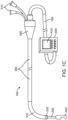
- the catheter 100 includes an elongate member 200, a longitudinal shaft component or outer shaft 300, a distal assembly 400, and a handle 500.
- the elongate member 200 and/or outer shaft 300 can be a cannula, tube, or other elongate structure having one or more lumens.
- the elongate member 200 and/or outer shaft 300 can be made of a flexible tube.
- a handle 400 in the proximal region of the elongate member 200 and outer shaft 300.
- the elongate member 200 and/or outer shaft 300 and/or handle 500 may be connected to a component (e.g.
- controller 600 which receives and/or sends information from/to the catheter 100 and/or has some level of control over functions of the catheter 100.
- Connection of the catheter 100 to the controller 600 may include a connector 700 which may include but is not limited to electrical, optical, mechanical, hydraulic, wireless, and combinations thereof.
- the handle may also incorporate all the functions of the controller in effect serving as an integral controller handle.
- the distal assembly 400 can house an energy delivery apparatus 410, for example, one or more ultrasound transducers (described in more detail in FIGS. 2A-F , 4 , 5 , 8 , 9 , and 10 ) and be connected to the distal region of the elongated member 200.
- an energy delivery apparatus 410 for example, one or more ultrasound transducers (described in more detail in FIGS. 2A-F , 4 , 5 , 8 , 9 , and 10 ) and be connected to the distal region of the elongated member 200.
- a distal assembly 400 having an ultrasound transducer as a source of energy
- Suitable sources of energy include but are not limited to, radio frequency (RF) energy, microwaves, photonic energy, and thermal energy. It is envisioned that the energy source to create necrotic tissue could alternatively be achieved using cooled fluids (e.g., cryogenic fluid).
- RF radio frequency
- a single ultrasound transducer is described herein as an exemplary energy delivery source, it is envisioned that a plurality of energy delivery structures can be included in the distal assembly 400 and that the energy may be delivered in a direct and/or reflected and/or refracted manner.
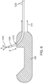
- the outer shaft 300 of the catheter 100 can include a deflectable region 310 as shown in FIG. 1C .
- the outer shaft 300 may be constructed of varying stiffness of materials to provide a relatively stiffer proximal section and more flexibility in the deflectable region 310, for example a high durometer polymer in the proximal region and a lower durometer polymer in the distal region. Multiple polymers and/or material thicknesses and properties may be used to accomplish varying stiffness. Additionally, continuously varying stiffness may be used. A very soft distal tip may also be comprised by varying stiffness and/or thickness in materials. Materials may also be layered over each other to accomplish the desired properties.
- Materials comprising the components used in the construction of the outer shaft 300 and/or elongated member 200 may be made from materials that are radiopaque under fluoroscopy and/or visualized by various imaging modalities (e.g. metals, polymers with radiopaque fillers, etc).
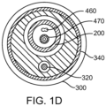
- the outer shaft 300 may include an additional structural element 340 or elements to provide the desired torque and flexibility properties including braided and coiled materials (e.g. metal, fiber, etc).
- Structural elements may be or similar or dissimilar materials and constructions, e.g. a braid in the proximal region and a coil in the distal region of the outer shaft 300.
- the outer shaft 300 and/or handle 500 can include a bending mechanism or mechanisms for bending the deflectable region 310 of the outer shaft 300 which may include a deflection element 320.
- the bending mechanism may include but is not limited to lengths of wires, ribbons, cables, lines, fibers, filament, combinations thereof, or any other actuating or force transmitting member.
- the bending mechanism includes one deflection element 320 comprised of two materials, for example, a distal Nitinol region and a proximal Kevlar filament region.
- FIG. 1D is a representative cross-section taken along the line A-A in FIG.
- the deflectable region may bend in one or multiple planes and be comprised of one or more deflectable segments giving the option of multiple degrees of freedom.
- the elongated member 200 may be constructed using similar methods and materials as described for the outer shaft 300 and may also be deflectable. To enhance the torque transmission of the elongate member 200 and/or outer shaft 300 may be constructed with counter wound coils made for example of flat, round, box section materials such as stainless steel. Radiopaque bands and or visual markers may be placed along the outer shaft 300 and/or elongate member 200. For example, a radiopaque band near the proximal end of the deflectable region 310 and one or more visual markers on the outside of the outer shaft 300 at specific distances from the end or an element of the catheter to aid in positioning of the catheter 100.
- the deflection element 320 may be connected in the distal portion of the deflectable region 310 to a radial band 330 to serve as an anchor.
- the radial band 330 may be radiopaque to provide visualization under fluoroscopy.
- attachment of the deflection element 320 may include but is not limited to using: adhesive, welding, pins, and/or screws or the like.
- the deflection element 320 may be terminated in the region of the handle and be actuated by one or more ways of moving the deflection element 320, for example screw(s), slider(s), gear(s), pulley(s), motor(s), electrical coil(s), and the like or combinations thereof.
- Position of the deflection element 320 or a portion of the catheter 100 may be desired.
- the use of a sensor or sensors may be used to accomplish this.
- sensors include but are not limited to optical, electrical, mechanical, magnetic, hydraulic, wireless, etc.
- Information from the sensors may be used to inform and/or modify system parameters and/or control features (e.g. intensity, speed, position, pull wire position or tension, motor position, etc).
- FIG. 1A shows the distal assembly 400, attached to the elongate member 200 in a somewhat retracted position with respect to the outer shaft 300. It is within the scope of the invention that the distal assembly may retract within the outer shaft 300 and that distal assembly 400 and elongated member 200 may be fully retractable or removable from the outer shaft 300.
- FIG. 1B shows the elongate member 200 and distal assembly 400 extended from the outer shaft 300 relative to the position shown in FIG. 1A . Movement of the elongate member 200 with respect to the outer shaft 300 may be actuated and/or controlled and/or monitored in the handle 500 or, according to the invention, in the controller 600.
- Rotational and/or translational movement may be accomplished by moving the elongated member 200 and/or outer shaft using , for example screw(s), slider(s), gear(s), pulley(s), motor(s), electrical coil(s), and the like or combinations thereof.
- Rotation and/or translation of elements of the catheter 100 may be desired to form tissue necrosis in various shapes, including but not limited to individual or combinations of continuous and/or intermittent lines (e.g. open, closed, crossing, etc), shapes, spots, patterns (e.g. spiral, helix, dashed lines, etc) as will be described in more detail in FIGS. 7A-D . Position of the either of both of these elements may be desired.
- sensors include but are not limited to optical, electrical, mechanical, magnetic, hydraulic, wireless, etc.
- Information from the sensors may be used to inform and/or modify system parameters and/or control features (e.g. intensity, speed, position, pull wire position or tension, motor position, etc).
- Control of the movement of any component of the catheter 100 may be accomplished by physical inputs and/or by use of a controller 600. These movements may be for example: pre-programmed, auto or semi-automated, input manually, or a combination thereof. Control of the energy delivery may also be in part controlled by the controller 600.
- the controller 600 may incorporate an integral or separate display 610 which may have touch screen inputs and/or soft keys.
- the controller 600 and/or display 610 may have various inputs and/or outputs, for example: power in, alarms, visual display(s) (e.g. display 610), energy control, position of catheter 100 element or elements (e.g.
- distal assembly 400 longitudinal and/or rotational), sensor input/output, power out, control of actuating elements, tissue necrosis shape or pattern, energy delivery ON/OFF, time of use, energy setting, energy delivered, tissue structure depth(s), nerve(s) location, calcified tissue, progression of lesion formation, indicator of lesion completion, external and/or additional equipment control (e.g. pumps), safety stops and limits, etc.
- the ability to regulate the use of the system and/or catheter 100 may be accomplished in, for example, the controller 600 or handle 100 where software and/or hardware monitors the use of the catheter 100 and only allows it to be functional for a determined amount of time and/or uses and/or energy delivery and the like. For example, once the catheter 100 delivers energy for the first time, there is a 4-hour clock which is started which after that has expired, the catheter 100 is no longer recognized by the controller 600 as being usable.
- Information from an element or elements of the system may be used for imaging and/or analysis of tissue (further referred to as "imaging") in or by the controller 600 and/or a separate component or instrument (not shown).
- This element or elements may be the same or different from the element or elements used to deliver energy to create necrotic tissue.
- Information from the element or elements may be used to determine distance from the element to a structure, to gather information about the structure or structures (e.g. thickness, morphology, physiology, multiple structures, structure recognition, tissue type, etc.), and other uses. Further this element or elements may be used to monitor the progression of a lesion while the lesion is created to titrate the energy delivered and/or stop energy delivery when the targeted lesion dimensions are achieved.
- the information gathered may be used to affect the energy delivered, including but not limited to intensity, duration, power, frequency, speed, etc, as well position of energy delivery. Examples include measuring wall thickness to determine energy dose parameters and identifying structures (e.g. nerve tissue) to determine energy delivery position. Imaging may be used to identify received echoes that are indicative of calcified regions where reflections are stronger than non-calcified tissue. Therapy power and intensity levels may be increased in these regions to insure effective therapy. Additional manual or automated guidance from the controller 600 and display 610 may direct the therapy to regions without substantial calcification as to insure effective therapy.
- Imaging may be accomplished independently or interleaved with the delivery of therapeutic energy. It is intended that the imaging energy level or time of energy delivery is such that an insufficient amount of energy is deposited in the tissue to damage the tissue (e.g. create thermal damage and/or tissue necrosis) from the imaging.
- an ultrasound wave may be delivered to the tissue by an energy deliver element 410, in this case an ultrasound transducer or transducers.
- the varying tissues and tissue interfaces reflect back energy, which is then received by the ultrasound transducer(s) or other transducers, and the delay time is used to calculate the relative tissue positions (e.g. blood vessel inner and outer wall).
- the wall thickness can be calculated and the energy delivery parameters can be adjusted, for example by the controller 600 and/or by the operator or a combination thereof, to ensure the appropriate depth of tissue necrosis is created from both an efficacy and a safety perspective.
- the energy delivery parameters can be adjusted prior to therapeutic energy delivery and/or during therapeutic energy, while the energy delivery apparatus is held in a specific position or is being moved with respect to the tissue (e.g. creating a line of tissue necrosis).
- Imaging can be used to determine the properties of tissues. As tissue necrosis is being created, the acoustic properties of the tissue changes. This can be evaluated to determine among other things, for example if the tissue is healthy, necrotic, the depth of necrotic tissue, and the like. As different structures have different acoustic properties such as nerve tissue compared to the blood vessel wall, these structures can be differentiated using similar imaging techniques. In this manner for example, nerve tissue can be identified and specifically targeted with therapeutic energy. It is envisioned that combinations of energy delivery and imaging can be combined to produce the desired results.
- the imaging and/or therapeutic information may be wholly or partly used in an image (e.g. 2 dimensional, 3 dimensional, layered, integrated) that may be static, dynamic, interactive, etc and shown on the display 610.
- an image e.g. 2 dimensional, 3 dimensional, layered, integrated
- the imaging may further incorporate coded excitation and reception for improving the signal-to-noise (SNR) ratio and/or improve the spatial resolution.
- SNR signal-to-noise
- the catheter and/or system may be constructed as to be visualized and/or recognized by and/or interface and/or integrated with additional equipment, including but not limited to fluoroscopy, pumps (e.g. fluid), computed tomography, magnetic resonance imaging, anatomical mapping, electrocardiogram, respiration, pumps, imaging, etc.
- Control of a pump(s) may be used to deliver fluids (e.g. cooling, drugs, etc) along or through elements of the catheter 100, for example: cooling fluid through the elongate member 200, saline through the outer shaft 300, etc.
- a pump or pumps may be integrated with the controller.
- the outer shaft 300 may be free to be moved at least in part rotationally and/or translationally with respect to the elongate member 200 by the proximal end of the outer shaft 300 terminating distal to the proximal end of the elongate member 200. Fixing the position between the two elements may be accomplished by using a seal, valve, locking mechanism, friction device or component or fit, etc and the like on one or more components.
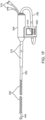
- FIG. 1F shows another embodiment of the invention wherein the catheter 100 has a partial outer shaft with the catheter 100 sized to pass through and/or use a sheath and/or guiding catheter for placement in the desired treatment region, or it may be used as a stand-alone device.
- the catheter shaft is constructed with an outer shaft 270 which may comprise one of more elements, and extend distally from the handle 500.
- the inner shaft may be constructed of one or more elements to accommodate varying stiffnesses, torqueability, dimensions, etc. As shown, the inner shaft comprises two elements, a proximal inner shaft 260 which is relatively stiffer, and a distal inner shaft 250 which is comparatively more flexible.
- Such elements may comprise coils, springs, support members, or sections of varying materials and geometries aimed towards altering local stiffness.
- the inner shaft may translate and /or rotate within the outer shaft 270.
- the catheter shaft may be inserted into a guiding catheter, a rotating hemostatic valve or Touhy-Borst adapter attached to the proximal end of the guiding catheter may be tightened down onto the outer shaft 270 to hold the catheter handle and outer shaft 270 in position with respect to the guiding catheter.
- the guiding catheter may be placed within the desired treatment area (e.g.
- the catheter 100 advanced through the guiding catheter until the distal assembly 400 is in position for imaging or therapy, the rotating hemostatic valve or Touhy-Borst adapter attached to the proximal end of the guiding catheter is tightened down onto the outer shaft 270, and then the movement of the inner shaft is controlled by the handle 500 and/or controller 600.
- the handle 500 and/or controller 600 Various details, features, and uses of this embodiment include those described herein regarding other embodiments.
- FIGS. 2A-B show representative examples of various embodiments of the distal assembly 400 with a single element energy delivery apparatus 410.
- a single element energy delivery apparatus 410 is shown in these embodiments for tissue necrosis energy delivery and/or imaging, but more than one element, such as multiple ultrasound transducers, may comprise the energy delivery apparatus 410.
- a single element energy delivery apparatus 410 may be used to create tissue necrosis while one or more (e.g. an array) of elements comprising the energy delivery apparatus 410 may be used for imaging.
- FIG. 2A shows the distal assembly 400 with a single element energy delivery apparatus 410 in this embodiment being an ultrasound transducer.
- the ultrasound transducer can include energy delivery wires 470 or other means which carry the signal to the handle 500 and/or controller 600. As shown, the energy delivery wires 470 are a coaxial cable.
- the ultrasound transducer is set in the distal assembly 400 such that the ultrasound energy is directed towards a reflector 420.
- the distal assembly housing 480 can be made to be atraumatic in shape (e.g. rounded and/or smooth surfaces), and may include a recess portion or design feature(s) to prevent damage to the tissue when moving the distal assembly within the patient.
- the reflector 420 reflects ultrasound energy out of the distal assembly 400 through the aperture 430.
- One or more apertures may be used and any portion or all of the energy may be reflected.
- the ultrasound transducer is held in position by a support 440.
- the support 440 and/or energy delivery apparatus 410 may be moveable with respect to other parts of the catheter, e.g. the energy delivery apparatus 410 may be moveable with respect to the aperture 430.
- the reflector 420 is planar, but can alternatively include a non-planar face, for example, a curved, convex, or concave surface.
- the angle of the reflector 420 can range below 180°. In one implementation the angle is substantially 0-90°. In another implementation the angle is substantially 30-60°. In another implementation the angle is substantially 40-50°. In a further embodiment the angle is substantially 45°.
- heat may be generated by the transducer. It is envisioned that the temperature can be controlled or affected by cooling the transducer. In one or more implementations cooling of the transducer can be accomplished by contacting the transducer subassembly with a fluid, for example, saline. In some implementations the transducer can be cooled using a fluid having a lower temperature relative to the temperature of the transducer. In one implementation a fluid for cooling the transducer is flushed past the transducer subassembly from a lumen in the catheter 100. Accordingly, as shown in FIGS.
- the proximal end of a lumen of the catheter 100 can be connected to a fluid port 510 or multiple fluid ports, for example, a luer fitting, in the region of the handle 500.
- the fluid used for cooling the transducer can exit the distal assembly 400 through one or more openings and/or fluid can be passed through and/or around other components such as the outer shaft 300 and/or elongate member 200.
- a temperature sensor 450 can be coupled with the energy delivery apparatus 410, for example, attached to the back side of the ultrasound transducer.
- the temperature sensor can be comprised of a thermocouple or a thermistor or any other suitable means.
- the temperature sensor 450 can include sensor wires 460 or other means which carry the signal to the handle 500 and/or controller 600.
- the ultrasound transducer can be attached to the support 440 in such a manner as to create a void or pocket between the ultrasound transducer and the support 440.
- the void or pocket can include a material which efficiently reflects sound waves generated by the ultrasound transducer.
- the material of the void or pocket can be air or any other suitable material such as metal or plastic which reflects acoustic waves.
- the acoustic waves thus can be directed to exit from the front face of the transducer, resulting in a minimum amount of acoustic energy lost out through the transducer back side.
- Acoustic matching layers can be attached, through bonding, to the front surface of the transducer. The acoustic matching layers improve the efficiency of the transduction of electrical energy to acoustic energy, and vice-versa. This also reduces the heat produced by the subassembly.
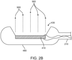
- FIG. 2B shows a cross-section of an additional version of a portion of the catheter 100 encompassing the energy delivery apparatus 410.
- the energy delivery apparatus 410 is positioned such that it is relatively aligned with the intended direction of energy delivery.
- the energy is delivered in a relatively radial direction, from less than 180 degrees to greater than 0 degrees, more preferably from 45 degrees to 135 degrees from the longitudinal axis.
- the energy delivery apparatus is positioned within the housing 480 facing the aperture 430, however, it is envisioned that the energy delivery apparatus 410 can also be positioned at or on the surface of the housing.
- Various details, features, and uses of this embodiment include those as described herein regarding other embodiments.
- FIG. 2F shows a cross-section of an additional version of a portion of the catheter 100 encompassing multiple energy delivery apparatus 410.
- a multiple element energy delivery apparatus 410 is positioned such that the elements are relatively aligned with the intended direction of energy delivery.
- the energy is delivered in a relatively radial direction, from less than 180 degrees to greater than 0 degrees, more preferably from 45 degrees to 135 degrees from the longitudinal axis, with the energy delivery apparatus 410 positioned within the housing 480 facing the aperture 430, however, it is envisioned that the energy delivery apparatus 410 can also be positioned at or on the surface of the housing.
- the energy delivery apparatus 410 may be positioned to create various patterns of energy for creating tissue necrosis and/or imaging as will be described in more detail elsewhere. Various details, features, and uses of this embodiment include those as described herein regarding other embodiments.
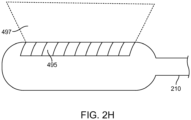
- FIG. 2G and 2H each show a partial circumferential surface view of an additional version of a portion of the catheter encompassing furthering of the energy delivery apparatus in one embodiment of the invention.
- a one-dimensional, or two-dimensional, array of transducer elements may be used to image the tissue before therapy delivery and/or during therapy delivery as described within the context of "imaging".
- imaging plane 497 or section of the imaging plane can be positioned within the beam 900 used for therapy where the latter therapy beam is distal to the imaging plane 497 per FIGS 2A-2F .
- the width of the imaging plane 497 (from acoustic diffraction) can overlap the therapy beam 900 if placed in close juxtaposition as in FIG. 2G or the imaging plane 497 may be steered electronically to reach more distally as show in FIG. 2H .
- Example energy delivery apparatus configurations for one-dimensional and two-dimensional arrays are shown in FIGS 9B and 9C .
- Two-dimensional arrays ( FIG 9C ) can steer distally into the therapy beam 900 in either preferred orientations as shown in FIG 2G and 2H if the one dimensional array 495 (as represented in FIG 9B ) is replaced with a two dimensional array 495 (as represented in FIG 9C ).
- FIG. 3 shows an additional catheter 100 distal section in another embodiment.
- the guide element 800 may be a guide wire.
- the guide element 800 may have a distally positioned guide element tip 810.
- the guide element tip 810 may be flexible, shapeable, atraumatic, and the like.
- the guide element 800 is passed through distal assembly 400 and the elongate member 200 for at least a portion of its length.
- the guide element 800 may be fixed in position, relatively fixed in position (e.g. movable within a limited range of motion in one or more directions), or free to move with respect to other components of the catheter, including being partially or completely removed from the catheter 100.
- recessing the energy delivery apparatus 410 may be advantageous to cooling the energy delivery apparatus 410, as well for providing a fluid and/or cooling fluid barrier between the energy delivery apparatus 410 and the blood.
- Features of the reflector 420 and/or the housing 480 and/or other additional elements may be used to create various patterns of energy as will be described in more detail elsewhere.
- the aperture 430 or apertures can be in part or completely covered and/or filled with an energy transparent and/or semi-transparent material. Additionally, components of the catheter 100 may be in part or entirely coated. The coating may be for example but not limited to: lubricious, anti-thrombogenic, biocompatible, and the like.
- FIG. 4 shows a cross-section of a representative energy beam profile in one of more embodiments'.
- the energy is ultrasound.
- the diameter of the ultrasound beam at the ultrasound transducer face is equal to, or less than, the diameter D1 of the ultrasound transducer.
- the ultrasound beam 900 converges slightly from the ultrasound transducer face out to a distance of L, beyond which the beam diverges with the minimum beam width D2 occurring at distance L.
- the above beam of similar diameters D1 and D2 may be collimated as to avoid a tight focus of increased intensity.
- a collimated beam delivers a substantially similar level of intensity over a distance that includes the vessel lumen and the tissue beyond the intimal lining that is targeted for treatment.
- An example ultrasound beam is one with a frequency of 11MHz and a transducer diameter of 2.0 mm providing a minimum beam width D2 of 0.8 mm at a distance of 7 mm.
- Various ultrasound transducer widths, shapes, and frequencies can be used to create the desired beam profile.
- the transducer or transducers may further be recessed within the housing 480 to move the maximum distance of energy divergence to a distance that insures a collimated beam will target the tissues of interest and the maximum distance of sufficient energy density is not too deep into the tissue.
- a lens or lenses as well as multiple transducers can be used to modify the beam profile as well, for example, to provide for a narrower or a wider region of tissue necrosis.
- the lens or lenses could be attached to the transducer or other component on the catheter 100 (e.g. the housing 480).
- Intensity levels from the beam of FIG 4 may be controlled by adjusting the time-varying voltages to the element 410. Higher intensity levels produce more heat in shorter time durations than lower intensities. Intensities for the embodiments herein are preferred to be less than 1000 W/cm 2 as defined by the spatial peak temporal peak intensity measured in water. Intensities above 1000 W/cm 2 are avoided to eliminate potential mechanical tissue damage caused by cavitation and preserve more precisely controlled therapy from targeted thermal damage. Avoiding intensities above 1000 W/cm 2 also minimizes the creation of microbubbles that may reflect ultrasound and hinder effective uniform therapy delivery. Preferred intensities in the blood are under 750 W/cm 2 .
- FIG 5 shows the spatial average temporal average acoustic intensity in blood for a representative acoustic beam as shown in FIG 4 .
- the spatial average is defined as the spatial average within the beam at each distance defined over the extent where the intensity is above the - 6 decibel level relative to the spatial peak intensity over all distances which is set to the zero decibel level.
- the maximum spatial average temporal average intensity does not exceed twice the minimum intensity.
- the beam remains substantially collimated down to a distance of 14mm.
- Relatively collimated beams are designed through the choice of the acoustic element type, the element(s) dimensions, the mechanical mounting conditions, and the acoustic frequencies of operation. Electronic defocusing with multiple elements can produce collimated beams. Mechanical lens may also be used to generate collimated beams.
- FIG. 5 shows a cross-section of a portion of the catheter encompassing the energy delivery apparatus 410 in a vessel 1000 (e.g. blood vessel) in one embodiment of the invention.
- a vessel 1000 e.g. blood vessel
- the energy can be used to create a motive force emanating from the face of the transducer resulting in acoustic pressure induced flow 910.
- This acoustic streaming from acoustic pressure induced flow 910 can interact with the fluid 520 being passed through the catheter 100 and/or with the blood to remove or reduce the amount of heat being generated at and/or near the tissue or vessel surface 1010, allowing for decreased damage at the vessel surface 1010, preserving the endothelial layer and/or at least a portion of the intima, thus increasing safety by reducing or eliminating, for example: thrombus formation, charring, restenosis, etc.
- Fluid 520 below body temperature e.g. room temperature or cooled
- Varying the rate of fluid flow can also effect the heat removal and higher fluid flows will remove heat more quickly.
- the energy delivery apparatus 410 is not in contact with the target tissue.
- the energy delivery apparatus can be distanced from the target tissue causing little or no damage to the target and surrounding tissues, both from a contact perspective (e.g. abrasion) and from the fact there is little or no thermal conductivity from the catheter 100 to the tissue.
- This is in dramatic contrast to typical RF ablation catheters used for creating lesions that must not only be in contact with the tissue, but the pressure with which they are positioned against the tissue affects the amount of tissue necrosis, not to mention the potential for thrombus formation and charring also known to negatively affect that energy delivery technology.
- One or more elements of the catheter 100 may be constructed to affect acoustic pressure induced flow 910, such as focusing the acoustic pressure induced flow 910 into a more narrow region or diverging it to cover a greater area.
- FIG. 6 shows the cross-section of a representative profile of a region of tissue necrosis 1100 that may be created with embodiments of this invention.
- tissue for example, a vessel 1000
- the energy is absorbed and converted into heat. This causes the temperature of the tissue to rise, which is offset by the tissues ability to remove heat to due blood circulation, thermal dissipation, etc.
- the width of a particular region of tissue necrosis 1100 will be wider near the entrance of the ultrasound beam 900 (e.g. the vessel surface 1010) and narrower farther away from it (e.g. deeper in the tissue 1000).
- Blood flow within the vessel 1000 as well as acoustic pressure induced flow 910 increase the thermal transfer at the vessel surface 1010 from the vessel surface 1010 to the blood and/or fluid delivered by the catheter. This increased rate of heat removal reduces the thermal damage at the vessel surface 1010. This can be affected by, for example: the flow rate, velocity, and temperature of the fluid passed through the catheter 100 as well as the power, frequency, pulse rate, duration, etc of the energy delivered among other factors. If desired, these parameters can be tailored such that the endothelial layer of the vessel 1000 is not permanently damaged.
- Tissue necrosis occurs when the tissue is heated above a temperature of 55 degrees Celsius.
- the region of tissue necrosis 1100, particularly depth of the region can be controlled.
- the ability to accurately control width and depth of the region of tissue necrosis 1100 provides for a safe and efficacious treatment. Being able to monitor changes within the tissue using imaging is an additional enhancement. Monitoring reflected amplitudes and the rate of change of these amplitudes can be used to monitor the progression of a thermal lesion. Changes in density and changes in the speed of sound can all be used to monitor treatment.
- FIGS. 7A-D show cross-sections of vessels with representative shapes of necrotic tissue. These shapes serve only as examples of what can be created with embodiments of the invention.
- One such example of creating a region of tissue necrosis 1100 in a patient is as follows:
- the distal assembly 400 is retracted, similarly it can be advanced or advanced and retracted and rotated if necessary to form the desired shape or shapes.
- the invention provides a system that is capable of creating regions of tissue necrosis 1100 that may be composed of one of more spots; lines of varying shapes, for example a spiral or helix; continuous or intermittent lines, circles, narrow or wide lines, and the like as well as combinations thereof.
- FIG. 7A shows a spiral region of tissue necrosis 1100.
- FIG. 7B shows multiple regions of tissue necrosis 1100 forming an intermittent spiral.
- FIG. 7C shows multiple regions of tissue necrosis 1100 forming a pattern of spots.
- FIG. 7D shows a circular region of tissue necrosis 1100.
- the handle 500 and/or controller 600 can be used to affect manual (e.g. operator input), semi-automatic, and/or fully-automatic control over various functions of the system, including but not limited to catheter 100 or catheter component movement, energy parameters, energy delivery, and imaging among others. Control in this manner allows for accurate placement and shape of the tissue necrosis pattern. By not having to manually reposition the energy delivery apparatus 410, the desired region(s) of tissue necrosis can be created in a more expeditious manner. Similarly, by having an energy beam the does not require tissue contact, the procedure can be conducted more quickly than if contact and/or a range of contact pressures is required.
- Accurate tissue necrosis patterns with controlled width and depth provides the operator with an easy-to-use system capable of quickly delivering an efficacious and safe therapy to the patient.
- FIG. 8 shows a portion of the catheter encompassing the energy delivery apparatus and a component to aid in pain reduction in embodiments of the invention.
- tissue necrosis 1100 depending on the tissue, the patient may feel pain associated with the thermal rise of the tissue (e.g. nerve tissue). As such, it is desirable to affect a decrease in the pain associated with creating tissue necrosis.
- a reduction in pain associated with creating tissue necrosis may be accomplished by delivering a pain reduction medicament or anesthetic or other fluid/gel/solid near the region of energy delivery or to a region that will affect the sensation of pain from the delivery of energy.
- the delivery of the pain reduction medicament or anesthetic or other fluid/gel/solid can take place prior to and/or during and/or after the delivery of energy.
- a feature may be incorporated on the catheter 100 to aid in delivering a pain reduction medicament or other fluid to the site of energy delivery.
- a fluid delivery tube 1200 e.g. a needle
- a fluid e.g. pain reduction medicament 1240
- the fluid delivery tube 1200 can be retracted into the distal assembly 400 or component of the catheter 100 through the fluid delivery tube port 1210.
- the fluid delivery tube 1200 can be retracted into the distal assembly 400 to enable atraumatic insertion and positioning at the intended site of energy delivery.
- fluid delivery tube 1200 can then be advanced out of the distal assembly 400 and positioned near or in the tissue either under manual control, such as by moving a fluid delivery tube actuator 1230 located more proximally on the catheter 100, or under some level of control by the controller 600 (e.g. semi-automatic, automatic).
- the fluid is then administered though the fluid delivery tube 1200 via a fluid delivery fitting 1220, such as a luer fitting and tube, located in a more proximal region of the catheter 100, for example on the handle 500.
- a fluid or gel can be passed through a lumen of the catheter 100, examples include: between the elongate member 200 and the outer shaft 300, through the elongate member 200 and out the distal assembly 400, etc.
- the fluid/gel can be mixed with the fluid used to remove heat from the energy delivery apparatus 410 and/or tissue as described previously.
- the ultrasound from the energy delivery apparatus may also be used to stimulate the efficiency of the drug delivery through sonoporation, bursting or altering encapsulated drug delivery vehicles, and thermal stimulated drug delivery. Injecting the drug directly into the fluid path 520 can avoid a separate needle delivery vehicle and may be most efficiently directed to the intimal layer of interest.
- FIG. 9A shows a top view of an energy delivery apparatus consistent with embodiments shown in Figs 2B , 2F , 2G , and 2H .
- Square or rectangular element dimensions are suited for energy directed from along the longitudinal dimension of the housing 480.
- This single element may deliver energy for therapy and energy for imaging by temporally interleaving electrical excitations of the element.
- Duty cycles defined by the duration of therapy divided by the duration of therapy and imaging are typically greater than 50%, and preferably above 75% as to maintain a sufficiently high rate of energy to heat the tissue to irreversible damage. Preferred duty cycle rates depend on the selected acoustic intensity as higher duty cycles may be required for lower acoustic intensities.
- FIG. 9B shows a top view of an energy delivery apparatus composed of a one dimensional array of elements consistent with embodiments shown in Figs 2B , 2F , 2G , and 2H .
- Elements contained within may share therapy and imaging actions per temporally interleaved excitations, or particular elements may be dedicated for either therapy or imaging.
- the advantage of using multiple elements is two-fold and is made possible by the use of electronic steering; acoustic beam forming with acoustic transducer elements.
- Imaging beams may be focused and steered in preferred directions to optimize spatial resolution and the reach of the field of view of the imaging plane. Therapy beams may be specifically defocused to preserve a substantially collimated beam for distance independent lesion formation.
- FIG. 9C shows a top view of an energy delivery apparatus composed of a two dimensional array of elements consistent with embodiments shown in Figs 2B , 2F , 2G , and 2H .
- This array configuration as the same advantages as discussed in FIG. 9B with the additional advantage that steering, focusing, and defocusing may be accomplished in more than a single plane.
- FIG. 10A shows a top view of an energy delivery apparatus consistent with embodiments shown in Figs 2A , 2G , and 2H .
- This single element may deliver energy for therapy and energy for imaging by temporally interleaving electrical excitations of the element.
- Duty cycles defined by the duration of therapy divided by the duration of therapy and imaging are typically greater than 50%, and preferably above 75% as to maintain a sufficiently high rate of energy to heat the tissue to irreversible damage.
- Preferred duty cycle rates depend on the selected acoustic intensity as higher duty cycles may be required for lower acoustic intensities.
- FIG. 10B shows a top view of an energy delivery apparatus composed of a one dimensional radial array of elements consistent with embodiments shown in Figs 2A , 2G , and 2H . More than two elements may be used although not shown here. Elements contained within may share therapy and imaging actions per temporally interleaved excitations, or particular elements may be dedicated for either therapy or imaging. The advantage of using multiple elements is two-fold. Imaging beams may be focused and steered along the axis of the main beam to optimize spatial resolution. Therapy beams may be specifically defocused to preserve a substantially collimated beam for distance independent lesion formation.
- FIG. 10C shows a top view of an energy delivery apparatus composed of a one dimensional array of elements consistent with embodiments shown in Figs 2A , 2G , and 2H .
- Elements contained within may share therapy and imaging actions per temporally interleaved excitations, or particular elements may be dedicated for either therapy or imaging.
- the advantage of using multiple elements is two-fold.
- Imaging beams may be focused and steered in preferred directions to optimize spatial resolution.
- Therapy beams may be specifically defocused to preserve a substantially collimated beam for distance independent lesion formation.
- FIG. 10D shows a top view of an energy delivery apparatus composed of a two dimensional array of elements consistent with embodiments shown in Figs 2A , 2G , and 2H .
- This array configuration as the same advantages as discussed in FIG. 10D with the additional advantage that steering, focusing, and defocusing may be accomplished in more than a single plane.
- FIG. 10E shows a top view of an energy delivery apparatus composed of a two dimensional array of elements consistent with embodiments shown in Figs 2A , 2G , and 2H .
- This array configuration is a further example of how a two dimensional array may be configured in one of many patterns.
Description
- The present invention describes apparatus for creating tissue necrosis. More specifically, this invention pertains to the creation of necrotic tissue having the effect of blocking conductive pathways. This invention may be used in the treatment of hypertension, cardiac, neurologic, renal, and various other disorders.
- Hypertension affects an estimated one billion patients worldwide. The kidney is directly involved in body fluid homeostasis, and its ability to excrete sodium chloride and maintain sodium balance, extracellular fluid volume, and blood volume are major factors in the regulation of long-term arterial pressure. Both the kidneys and the autonomic nervous system contribute to kidney function, with the two being linked through the renal nerves.
- The renal sympathetic nerves play a significant role in the pathophysiology of hypertension, where increased stimulation of these nerves triggers changes in renal vascular resistance, renin release, and retention of water and sodium. The afferent renal nerves monitor pressure changes in the kidney and relay the information to the central nervous system which then influences function of effector organs. Renal receptors influence cardiovascular function via increased activity of the sympathetic nerves to the kidney and other vascular beds and organs. The increase in sympathetic nerve activity and the activation of afferent renal nerves directly contributes to hypertension.
- Untreated, hypertension can lead or contribute to cardiovascular (e.g. myocardial infarction, congestive heart failure), neurologic (e.g. stroke, dementia), and renal (e.g. chronic renal failure) disorders all having a direct effect on morbidity and mortality. Current therapies for hypertension primarily consist of lifestyle changes and pharmacological therapy, with varying degrees of success. In a subset of these patients with persistent hypertension, interventional therapy has been tested.
- Initial treatment for hypertension is a change in lifestyle, including: diet, exercise, and weight loss, as well as elimination of smoking. Dietary modifications include limiting sodium intake, and consumption of nuts, whole grains, fish, poultry, fruits, and vegetables. In addition, a decrease in the consumption of red meats, sweets, and sugar is recommended. Exercise, weight loss, and non-smoking all contribute to improved cardiovascular function and decreased cardiac demand.
- Pharmacologic approaches consist of individual or combinations of antihypertensive drugs, namely: diuretics, which reduce blood volume by eliminating sodium and water; beta blockers, which reduce cardiac workload and dilate blood vessels; angiotensin-converting enzyme inhibitors; Angiotensin II receptor blockers; and calcium channels blockers, all of which dilate blood vessels and may reduce heart rate; and renin inhibitors which decrease the production of renin, an enzyme in the chain that increases blood pressure. In addition to these medications, in certain cases these drugs are administered: alpha blockers, to reduce vasoconstrictive chemicals; alpha-beta blockers, which also reduce cardiac output; central nervous system agents to reduce vasoconstriction; and vasodilators, used to increase vessel diameter and reduce pressure. Combinations of all these medications are administered in light of their different effects on patients of varying race, gender, and age.
- Patients taking multiple simultaneous medications without relief of hypertension are considered to have resistant hypertension. In the case of resistant hypertension, an invasive approach wherein the functionality of the renal nerves or sympathetic nervous elements is decreased or eliminated is proposed. This approach may also be applicable as a therapy for controlled hypertension.
- While existing therapies may have demonstrated a limited effect in treating these disorders, improved systems and methods for creating necrotic tissue and effecting nerve activity are needed. Furthermore, it would be desirable for such systems to have an increased control in, for example: position, profile, and morphology of the generated necrotic tissue, while also offering greater patient safety and ultimately greater efficacy. 2. Background Art. Other devices based on ultrasound energy to create lesions are described in
US Patent Nos. 6,997,925 ;6,966,908 ;6,964,660 ;6,954,977 ;6,953,460 ;6,652,515 ;6,547,788 ; and6,514,249 to Maguire et al. ;6,955,173 ;6,052,576 ;6,305,378 ;6,164,283 ; and6,012,457 to Lesh ;6,872,205 ;6,416,511 ;6,254,599 ;6,245,064 ; and6,024,740; to Lesh et al. ;6,383,151 ;6,117,101 ; andWO 99/02096 to Diederich et al. 6,635,054 to Fjield et al. 6,780,183 to Jimenez et al. 6,605,084 to Acker et al. 5,295,484 to Marcus et al. WO 2005/117734 to Wong et al. Other related patents and patent publications include:6,978,174 7,162,303 7,617,005 7,620,451 7,647,115 7,653,438 7,717,948 7,756,583 7,853,333 7,873,417 7,937,143 US20060212078 ;US20070173899 ;US20100137952 ;US20110060324 ;US20060212076 ;US20070265687 ;US20100168731 ;US20110112400 ;US20060265014 ;US20080213331 ;US20100168739 ;US20110166499 ;US20060265015 ;US20080255642 ;US20100174282 ;US20110178570 ;US20060271111 ;US20090036948 ;US20100191112 ;US20110200171 ;US20060276852 ;US20090062873 ;US20100222851 ;US20110202098 ;US20060025821 ;US20090076409 ;US20100222854 ;US20110208096 ;US20070129720 ;US20100137860 ;US20100249773 ;US20110257564 ;US20050234523 ;US20060041277 ;US20100268307 ;US20110264011 ;US20100010567 ;US20110264075 .WO2007134258 describes a cardiac ablation system including an ablation catheter having an anchor adapted to support the ablation catheter within an atrium of a heart and an ultrasound emitter disposed radially outward from a rotation axis and from the anchor, and a control mechanism adapted to rotate the ultrasound emitter about the rotation axis and to provide ablation energy to the ultrasound emitter to ablate heart tissue. - The present invention provides medical systems to create tissue necrosis, and more specifically to medical systems used to deliver energy to tissue in the treatment of hypertension, cardiac, neurologic, renal, and other medical conditions.
- The invention is defined in
independent claim 1, and further embodiments are defined in the dependent claims. Described is a method for creating tissue necrosis, the method comprising the steps of: providing a catheter that carries an energy delivery apparatus, positioning the energy delivery apparatus adjacent a vessel without contact therebetween, delivering collimated energy from the energy delivery apparatus to the vessel, and creating sufficient damage to the tissue with the collimated energy to cause tissue necrosis. In some embodiments of the invention delivering collimated energy comprises delivering ultrasound energy. Some examples may also include the step of cooling the energy delivery apparatus. - Additionally, some examples comprise irrigating the energy delivery apparatus with a fluid.
- In some examples, creating sufficient damage may comprise creating one or more linear tissue necrosis regions. The one or more linear necrosis regions may further comprise lesions selected from the group consisting of arc, spiral, helix, straight, dashed, freeform line, or variations or combinations thereof.
- In some examples causing tissue necrosis is conducted at least in part by semi-automated control. Causing tissue necrosis may also be conducted at least in part by automated control.
- According to the invention delivering collimated energy comprises delivering the energy to the tissue in a substantially radial direction.
- Some embodiments of invention feature a controller which controls the energy delivery.
- The exemplary method of creating tissue necrosis may further comprise deflecting a shaft of the catheter thereby facilitating positioning of the catheter at a target location. Some examples further comprise sensing or measuring a position and/or an orientation of an element of the catheter, and adjusting a control feature in response to the sensed or measured information obtained.
- Some examples also comprise the step of delivering energy to the tissue in order to determine information pertaining to one or more of the following: tissue structures, morphology, physiology, nerves, calcified regions, vessel wall thickness, distance from the energy delivery apparatus to a structure, and progression of lesion formation. Such examples may further comprise adjusting parameters of the energy delivered and/or adjusting movement of an element of the catheter in response to the information received.
- Some examples also comprise the step of delivering a pain reduction medicament. The delivered energy mentioned above may also enhance delivery of the pain reduction medicament to a tissue through one or more of the following: acoustic pressure or streaming, sonoporation, bursting or altering encapsulated drug delivery vehicles, or thermal stimulation.
- In some examples the vessel comprises a renal vessel, and tissue necrosis comprises necrosis of a nerve. Necrosis of the nerve may alleviate hypertension in a patient.
- Another example of the method for creating tissue necrosis comprises:
directing an energy delivery apparatus percutaneously to a target vessel, positioning the energy delivery apparatus in a desired location within the target vessel, initiating energy delivery, and moving the energy delivery apparatus while deliverying energy to create a desired region of tissue necrosis. - Some examples further comprise turning power on and off to the energy delivery apparatus while moving the energy delivery apparatus or in between movement of the energy delivery apparatus.
- Some examples further comprise imaging during or interleaved with the creation of tissue necrosis.
- Another aspect of the present invention entails, a system for creating necrotic tissue in a patient comprising a catheter (also referred to as energy delivery catheter) suitable for delivering energy sufficient to create tissue necrosis. The catheter may be constructed to enable radial and/or longitudinal movement of the energy delivery apparatus with respect to other components or structures of the catheter, or other devices (e.g. sheath or guiding catheter). The energy delivery apparatus comprising one or more elements capable of delivering and/or receiving energy, such as one or more ultrasound transducers. The catheter may be connected to a component (e.g. controller and/or generator) which receives and/or sends information from/to the catheter and/or has some level of control over functions of the catheter. The catheter may have one or more deflectable sections in the distal region of the catheter, the deflectable section(s) being delectable in one or more than one plane. The deflectable sections may be on the same shaft or on relatively independent shafts (e.g. coaxial shafts).
- In another aspect of the present invention, movement of the deflecting section or sections may be facilitated by pull and/or push element or elements (e.g. wires, fibers, combinations thereof, etc.) This element or elements may function with a supporting element or elements (e.g. surrounded at least in part by a coil or element with fixed or varying compressive strength). In addition, the supporting element or elements may be stationary, movable, or capable of being temporarily or permanently fixed in a given position.
- According to the present invention, the energy delivery apparatus is radial-firing. The energy may be direct or reflected to the target tissue.
- In another aspect of the present invention, components or elements of the catheter may be straight, preshaped, or deflectable to one or more desired configurations.
- In another aspect of the present invention, the catheter may be configured to be used over a guide wire or have an integral guide wire or guide member.
- In another aspect of the present invention, the catheter may have an atraumatic distal region or tip.
- In another aspect of the present invention, a handle may be connected to the catheter which enhances manipulation of the catheter. The handle may have a drive mechanism or mechanisms for movement of the energy delivery apparatus with respect to other components or structures of the catheter, or other devices. The handle may provide feedback or receive information from the controller and or generator and/or catheter.
- In another aspect of the present invention, the generator and controller may be combined in an integrated unit.
- In another aspect of the present invention, the generator and/or controller may be integrated with the handle.
- In another aspect of the present invention, movement and/or actuation of the energy delivery apparatus may be at least in part controlled by the controller and/or generator. These movements may be for example: pre-programmed, auto or semi-automated, input manually, or any combination thereof.
- In another aspect of the present invention, the catheter and/or component and/or components which receives and/or sends information from/to the catheter and/or has some level of control over functions of the catheter may provide the ability to determine or limit use of the catheter or component or components.
- In another aspect of the present invention, the energy delivered to create the necrotic tissue may be ultrasound.
- In another aspect of the present invention, the energy delivered to create the necrotic tissue may be ultrasound in a relatively collimated beam. This energy may be delivered from one or more ultrasound elements.
- In another aspect of the present invention, the energy delivery apparatus may be positioned within a structure. The structure may be designed to maintain a blood barrier of fluid between a certain component(s) and/or element(s).
- In another aspect of the present invention, the energy delivery apparatus may be directly or indirectly cooled. The effect of cooling the element of elements may aide in the overall performance of the system, including but not limited to efficiency, safety, and therapeutic effect.
- According to the present invention, the energy delivery apparatus is configured to deliver the collimated beam of energy to the target tissue within a wall of the vessel without directly contacting the vessel.
- In another aspect of the present invention, the energy may be delivered to create greater tissue necrosis within the target tissue than at the surface of the target tissue.
- In another aspect of the present invention, the energy may be delivered to form tissue necrosis in various shapes, including but not limited to individual or combinations of continuous and/or intermittent lines (e.g. open, closed, crossing, etc), shapes, spots, patterns (e.g. spiral, helix, dashed lines, etc). Any of these may be created by computer and/or mechanical control and/or assist and/or by or with or without operator input.
- In another aspect of the present invention, the catheter may be designed to provide acoustic pressure induced flow (e.g. blood, cooling fluid, etc) in the region of energy delivery. The induced flow may remove heat from the surface of the target tissue allowing less or no damage at the tissue surface, preserving the endothelium and/or intimal layer and increasing safety (reduction in thrombus, charring, stenosis, etc.)
- In another aspect of the present invention, an element or elements of the system may be used for imaging and/or analysis of tissue. This element or elements may be the same or different from the element or elements used to deliver energy to create necrotic tissue. Information from the element or elements may be used to determine distance from the element to a structure, to gather information about the structure or structures (e.g. thickness, morphology, physiology, multiple structures, structure recognition, calcified tissue, nerve location and depth, etc.), and other uses. In addition, the information gathered may be used to affect the energy delivered, including but not limited to intensity, duration, power, frequency, speed, etc, as well position of energy delivery. Examples include measuring wall thickness to determine energy dose parameters and identifying structures to determine energy delivery position and intensity. The structure in the region of the energy delivery apparatus (e.g. ultrasound transducer or transducers) may be constructed to improve the signal to noise ratio of the system. In addition, software may be used in or by the system to improve the signal to noise ratio.
- In another aspect of the invention, the energy delivery apparatus may be composed of a one- or multi-dimensional array of elements.
- In another aspect of the present invention, the imaging and/or therapeutic information may be wholly or partly used in a display image (e.g. 2 dimensional, 3 dimensional, layered, integrated) that may be static, dynamic, interactive, etc.
- In another aspect of the present invention, the catheter and/or system may be constructed as to be visualized and/or recognized by and/or interface with additional equipment, including but not limited to fluoroscopy, pumps (e.g. fluid), anatomical mapping, respiration, computed tomography, magnetic resonance imaging, etc.
- In another aspect of the invention the catheter, may comprise one or more elements to accommodate varying degrees of stiffness. For instance a proximal segment of the catheter may be relatively stiffer when compared to a distal portion of a catheter.
- In another aspect of the invention, the catheter may be sized to pass through a guiding sheath or guiding catheter. The catheter of this or any other embodiment of the invention may comprise an inner shaft and an outer shaft, wherein the inner shaft is translatable and/or rotatable with respect to the outer shaft. When used with a guiding catheter, the guiding catheter (or sheath) may be selectively clamped or tightened down on the outer shaft of the catheter used for energy delivery. This leaves the inner shaft slidable and/ or rotatable with respect to the outer shaft and guiding catheter. The inner shaft may then used to guide the energy delivery element. The inner shaft may comprise one or more elements to accommodate varying degrees of stiffness. For example, the inner shaft may be constructed to be stiffer in its proximal portions relative to its distal portions. Such elements may comprise coils, springs, support members, or sections of varying materials and geometries aimed towards altering local stiffness.
- In another aspect of the present invention, the catheter has the ability to affect a decrease in the pain associated with delivery of energy and/or creating tissue necrosis, especially necrosis of nerves. This may be accomplished for example, by localized drug delivery through or around the catheter. A suitable pain reduction medicament may be combined with the cooling fluid and delivered directly to the region of energy delivery. Additionally, an agent may be delivered via a component or components on, within, about, and/or passed through the catheter (e.g. port, needle(s), retractable needle(s), etc) to affect the nerves and/or surrounding tissue and decrease the pain of creating tissue necrosis. Further, the ultrasound may also be used to stimulate the drug delivery through sonoporation, bursting or altering encapsulated drug delivery vehicles, and/or thermal stimulated drug delivery.
- Descriptions of the embodiments presented herein are understood to be nonlimiting. It is understood that features and elements described in the different embodiments above and below may combined with each other.
- These and other embodiments are described in further detail in the following description related to the appended drawing figures.
- The novel features of the invention are set forth with particularity in the appended claims. A better understanding of the features and advantages of the present invention will be obtained by reference to the following detailed description that sets forth illustrative embodiments, in which the principles of the invention are utilized, and the accompanying drawings of which:
-
FIGS. 1A-C show side views of a catheter and handle including a controller in embodiments of the invention. -
FIG. 1D shows a cross-section of the catheter ofFIG. 1A-C taken at line segment A-A fromfigure 1A . -
FIG. 1F shows as side view of an additional embodiment having an inner shaft constructed of one or more elements to accommodate varying stiffness, torqueability, and dimensions. -
FIG. 2A shows a partial cross-section of a portion of the catheter encompassing the energy delivery apparatus in one embodiment of the invention. -
FIG. 2B shows a partial cross-section of an additional version of a portion of the catheter encompassing the energy delivery apparatus in one embodiment of the invention. -
FIG. 2F shows a partial cross-section of an additional version of a portion of the catheter encompassing multiple energy delivery apparatus in another embodiment. -
FIG. 2G shows a partial circumferential surface view of an additional version of a portion of the catheter encompassing further energy delivery apparatus in another embodiment. -
FIG. 2H shows a partial circumferential surface view of an additional version of a portion of the catheter encompassing further energy delivery apparatus in another embodiment. -
FIG. 3 shows a partial cross-section of a catheter distal section including a guide wire in another embodiment. -
FIG. 4A shows a representative energy beam profile in embodiments of the invention. -
FIG. 4B shows an acoustic intensity profile as a function of distance from the energy delivery apparatus in various embodiments. -
FIG. 5 shows a partial cross-section of a portion of the catheter encompassing the energy delivery apparatus in a vessel in another embodiment. -
FIG. 6 shows a cross-section of a representative profile of necrotic tissue that may be created in various embodiments of the invention. -
FIGS. 7A-D show cross-sections of vessels with representative shapes of necrotic tissue in embodiments of the invention. -
FIG. 8 shows a partial cross-section of a portion of the catheter encompassing the energy delivery apparatus and a component to enable pain reduction in an embodiment. -
FIG. 9A shows a top view of an energy delivery apparatus consistent with embodiments shown inFigs 2B ,2F ,2G , and2H . -
FIG. 9B shows a top view of an energy delivery apparatus composed of a one dimensional array of elements consistent with embodiments shown inFigs 2B ,2F ,2G , and2H . -
FIG. 9C shows a top view of an energy delivery apparatus composed of a two dimensional array of elements consistent with embodiments shown inFigs 2B ,2F ,2G , and2H . -
FIG. 10A shows a top view of an energy delivery apparatus consistent with embodiments shown inFigs 2A ,2G , and2H . -
FIG. 10B shows a top view of an energy delivery apparatus composed of a one dimensional radial array of elements consistent with embodiments shown inFigs 2A ,2G , and2H . -
FIG. 10C shows a top view of an energy delivery apparatus composed of a one dimensional array of elements consistent with embodiments shown inFigs 2A ,2G , and2H . -
FIG. 10D shows a top view of an energy delivery apparatus composed of a two dimensional array of elements consistent with embodiments shown inFigs 2A ,2G , and2H . -
FIG. 10E shows a top view of an energy delivery apparatus composed of a two dimensional array of elements consistent with embodiments shown inFigs 2A ,2G , and2H . - The invention described herein describes a system and methods for creating tissue necrosis. The
catheter 100 of the invention includes anelongate member 200. The elongate member includes adistal assembly 400 encompassing an energy delivery apparatus and supporting structure for directing energy to tissue. Uses of the invention include but are not limited to creating tissue necrosis, and more specifically for the treatment hypertension, cardiac, neurologic, renal, and various other disorders. - One aspect of a first embodiment of the invention is shown in
FIGS. 1A-D . As shown, thecatheter 100 includes anelongate member 200, a longitudinal shaft component orouter shaft 300, adistal assembly 400, and ahandle 500. In other implementations, theelongate member 200 and/orouter shaft 300 can be a cannula, tube, or other elongate structure having one or more lumens. Theelongate member 200 and/orouter shaft 300 can be made of a flexible tube. Also shown is ahandle 400 in the proximal region of theelongate member 200 andouter shaft 300. Theelongate member 200 and/orouter shaft 300 and/or handle 500 may be connected to a component (e.g. controller 600) which receives and/or sends information from/to thecatheter 100 and/or has some level of control over functions of thecatheter 100. Connection of thecatheter 100 to thecontroller 600 may include aconnector 700 which may include but is not limited to electrical, optical, mechanical, hydraulic, wireless, and combinations thereof. The handle may also incorporate all the functions of the controller in effect serving as an integral controller handle. - The
distal assembly 400 can house anenergy delivery apparatus 410, for example, one or more ultrasound transducers (described in more detail inFIGS. 2A-F ,4 ,5 ,8 ,9 , and10 ) and be connected to the distal region of theelongated member 200. - Although the system described herein includes a
distal assembly 400 having an ultrasound transducer as a source of energy, it is envisioned than any of a number of energy sources can be used with various implementations of the invention. Suitable sources of energy include but are not limited to, radio frequency (RF) energy, microwaves, photonic energy, and thermal energy. It is envisioned that the energy source to create necrotic tissue could alternatively be achieved using cooled fluids (e.g., cryogenic fluid). Additionally, although use of a single ultrasound transducer is described herein as an exemplary energy delivery source, it is envisioned that a plurality of energy delivery structures can be included in thedistal assembly 400 and that the energy may be delivered in a direct and/or reflected and/or refracted manner. - The
outer shaft 300 of thecatheter 100 can include adeflectable region 310 as shown inFIG. 1C . Theouter shaft 300 may be constructed of varying stiffness of materials to provide a relatively stiffer proximal section and more flexibility in thedeflectable region 310, for example a high durometer polymer in the proximal region and a lower durometer polymer in the distal region. Multiple polymers and/or material thicknesses and properties may be used to accomplish varying stiffness. Additionally, continuously varying stiffness may be used. A very soft distal tip may also be comprised by varying stiffness and/or thickness in materials. Materials may also be layered over each other to accomplish the desired properties. Materials comprising the components used in the construction of theouter shaft 300 and/orelongated member 200 may be made from materials that are radiopaque under fluoroscopy and/or visualized by various imaging modalities (e.g. metals, polymers with radiopaque fillers, etc). Theouter shaft 300 may include an additionalstructural element 340 or elements to provide the desired torque and flexibility properties including braided and coiled materials (e.g. metal, fiber, etc). Structural elements may be or similar or dissimilar materials and constructions, e.g. a braid in the proximal region and a coil in the distal region of theouter shaft 300. - The
outer shaft 300 and/or handle 500 can include a bending mechanism or mechanisms for bending thedeflectable region 310 of theouter shaft 300 which may include adeflection element 320. The bending mechanism may include but is not limited to lengths of wires, ribbons, cables, lines, fibers, filament, combinations thereof, or any other actuating or force transmitting member. In one implementation the bending mechanism includes onedeflection element 320 comprised of two materials, for example, a distal Nitinol region and a proximal Kevlar filament region. A variety of attachment elements and positions for connecting the bending mechanism and the elongate member are envisioned.FIG. 1D is a representative cross-section taken along the line A-A inFIG. 1A ,of theouter shaft 300 showing theelongate member 200, a deflection element 320 (e.g. pull wire), and astructural element 340. The deflectable region may bend in one or multiple planes and be comprised of one or more deflectable segments giving the option of multiple degrees of freedom. Theelongated member 200 may be constructed using similar methods and materials as described for theouter shaft 300 and may also be deflectable. To enhance the torque transmission of theelongate member 200 and/orouter shaft 300 may be constructed with counter wound coils made for example of flat, round, box section materials such as stainless steel. Radiopaque bands and or visual markers may be placed along theouter shaft 300 and/orelongate member 200. For example, a radiopaque band near the proximal end of thedeflectable region 310 and one or more visual markers on the outside of theouter shaft 300 at specific distances from the end or an element of the catheter to aid in positioning of thecatheter 100. - The
deflection element 320 may be connected in the distal portion of thedeflectable region 310 to aradial band 330 to serve as an anchor. Theradial band 330 may be radiopaque to provide visualization under fluoroscopy. Similarly, attachment of thedeflection element 320 may include but is not limited to using: adhesive, welding, pins, and/or screws or the like. Proximally, thedeflection element 320 may be terminated in the region of the handle and be actuated by one or more ways of moving thedeflection element 320, for example screw(s), slider(s), gear(s), pulley(s), motor(s), electrical coil(s), and the like or combinations thereof. Position of thedeflection element 320 or a portion of thecatheter 100 may be desired. The use of a sensor or sensors may be used to accomplish this. Examples of sensors include but are not limited to optical, electrical, mechanical, magnetic, hydraulic, wireless, etc. Information from the sensors may be used to inform and/or modify system parameters and/or control features (e.g. intensity, speed, position, pull wire position or tension, motor position, etc). - The
elongate member 200 andouter shaft 300 rotate and translate with respect to each other.FIG. 1A shows thedistal assembly 400, attached to theelongate member 200 in a somewhat retracted position with respect to theouter shaft 300. It is within the scope of the invention that the distal assembly may retract within theouter shaft 300 and thatdistal assembly 400 andelongated member 200 may be fully retractable or removable from theouter shaft 300.FIG. 1B shows theelongate member 200 anddistal assembly 400 extended from theouter shaft 300 relative to the position shown inFIG. 1A . Movement of theelongate member 200 with respect to theouter shaft 300 may be actuated and/or controlled and/or monitored in thehandle 500 or, according to the invention, in thecontroller 600. Rotational and/or translational movement may be accomplished by moving theelongated member 200 and/or outer shaft using , for example screw(s), slider(s), gear(s), pulley(s), motor(s), electrical coil(s), and the like or combinations thereof. Rotation and/or translation of elements of the catheter 100 (e.g. distal assembly 400) may be desired to form tissue necrosis in various shapes, including but not limited to individual or combinations of continuous and/or intermittent lines (e.g. open, closed, crossing, etc), shapes, spots, patterns (e.g. spiral, helix, dashed lines, etc) as will be described in more detail inFIGS. 7A-D . Position of the either of both of these elements may be desired. The use of a sensor or sensors may be used to accomplish this. Examples of sensors include but are not limited to optical, electrical, mechanical, magnetic, hydraulic, wireless, etc. Information from the sensors may be used to inform and/or modify system parameters and/or control features (e.g. intensity, speed, position, pull wire position or tension, motor position, etc). - Control of the movement of any component of the
catheter 100 may be accomplished by physical inputs and/or by use of acontroller 600. These movements may be for example: pre-programmed, auto or semi-automated, input manually, or a combination thereof. Control of the energy delivery may also be in part controlled by thecontroller 600. Thecontroller 600 may incorporate an integral orseparate display 610 which may have touch screen inputs and/or soft keys. Thecontroller 600 and/ordisplay 610 may have various inputs and/or outputs, for example: power in, alarms, visual display(s) (e.g. display 610), energy control, position ofcatheter 100 element or elements (e.g. distal assembly 400 - longitudinal and/or rotational), sensor input/output, power out, control of actuating elements, tissue necrosis shape or pattern, energy delivery ON/OFF, time of use, energy setting, energy delivered, tissue structure depth(s), nerve(s) location, calcified tissue, progression of lesion formation, indicator of lesion completion, external and/or additional equipment control (e.g. pumps), safety stops and limits, etc. - The ability to regulate the use of the system and/or
catheter 100 may be accomplished in, for example, thecontroller 600 or handle 100 where software and/or hardware monitors the use of thecatheter 100 and only allows it to be functional for a determined amount of time and/or uses and/or energy delivery and the like. For example, once thecatheter 100 delivers energy for the first time, there is a 4-hour clock which is started which after that has expired, thecatheter 100 is no longer recognized by thecontroller 600 as being usable. - Information from an element or elements of the system (e.g. energy delivery apparatus 410) may be used for imaging and/or analysis of tissue (further referred to as "imaging") in or by the
controller 600 and/or a separate component or instrument (not shown). This element or elements may be the same or different from the element or elements used to deliver energy to create necrotic tissue. Information from the element or elements may be used to determine distance from the element to a structure, to gather information about the structure or structures (e.g. thickness, morphology, physiology, multiple structures, structure recognition, tissue type, etc.), and other uses. Further this element or elements may be used to monitor the progression of a lesion while the lesion is created to titrate the energy delivered and/or stop energy delivery when the targeted lesion dimensions are achieved. In addition, the information gathered may be used to affect the energy delivered, including but not limited to intensity, duration, power, frequency, speed, etc, as well position of energy delivery. Examples include measuring wall thickness to determine energy dose parameters and identifying structures (e.g. nerve tissue) to determine energy delivery position. Imaging may be used to identify received echoes that are indicative of calcified regions where reflections are stronger than non-calcified tissue. Therapy power and intensity levels may be increased in these regions to insure effective therapy. Additional manual or automated guidance from thecontroller 600 anddisplay 610 may direct the therapy to regions without substantial calcification as to insure effective therapy. - Imaging may be accomplished independently or interleaved with the delivery of therapeutic energy. It is intended that the imaging energy level or time of energy delivery is such that an insufficient amount of energy is deposited in the tissue to damage the tissue (e.g. create thermal damage and/or tissue necrosis) from the imaging. With respect to wall thickness, an ultrasound wave may be delivered to the tissue by an energy deliver
element 410, in this case an ultrasound transducer or transducers. The varying tissues and tissue interfaces reflect back energy, which is then received by the ultrasound transducer(s) or other transducers, and the delay time is used to calculate the relative tissue positions (e.g. blood vessel inner and outer wall). From this, the wall thickness can be calculated and the energy delivery parameters can be adjusted, for example by thecontroller 600 and/or by the operator or a combination thereof, to ensure the appropriate depth of tissue necrosis is created from both an efficacy and a safety perspective. The energy delivery parameters can be adjusted prior to therapeutic energy delivery and/or during therapeutic energy, while the energy delivery apparatus is held in a specific position or is being moved with respect to the tissue (e.g. creating a line of tissue necrosis). - Imaging can be used to determine the properties of tissues. As tissue necrosis is being created, the acoustic properties of the tissue changes. This can be evaluated to determine among other things, for example if the tissue is healthy, necrotic, the depth of necrotic tissue, and the like. As different structures have different acoustic properties such as nerve tissue compared to the blood vessel wall, these structures can be differentiated using similar imaging techniques. In this manner for example, nerve tissue can be identified and specifically targeted with therapeutic energy. It is envisioned that combinations of energy delivery and imaging can be combined to produce the desired results.
- The imaging and/or therapeutic information may be wholly or partly used in an image (e.g. 2 dimensional, 3 dimensional, layered, integrated) that may be static, dynamic, interactive, etc and shown on the
display 610. - The imaging may further incorporate coded excitation and reception for improving the signal-to-noise (SNR) ratio and/or improve the spatial resolution.
- In another aspect of the present invention, the catheter and/or system may be constructed as to be visualized and/or recognized by and/or interface and/or integrated with additional equipment, including but not limited to fluoroscopy, pumps (e.g. fluid), computed tomography, magnetic resonance imaging, anatomical mapping, electrocardiogram, respiration, pumps, imaging, etc. Control of a pump(s) may be used to deliver fluids (e.g. cooling, drugs, etc) along or through elements of the
catheter 100, for example: cooling fluid through theelongate member 200, saline through theouter shaft 300, etc. A pump or pumps may be integrated with the controller. - The
outer shaft 300 may be free to be moved at least in part rotationally and/or translationally with respect to theelongate member 200 by the proximal end of theouter shaft 300 terminating distal to the proximal end of theelongate member 200. Fixing the position between the two elements may be accomplished by using a seal, valve, locking mechanism, friction device or component or fit, etc and the like on one or more components. - Various details, features and uses of this embodiment include those as described herein regarding other embodiments.
-
FIG. 1F shows another embodiment of the invention wherein thecatheter 100 has a partial outer shaft with thecatheter 100 sized to pass through and/or use a sheath and/or guiding catheter for placement in the desired treatment region, or it may be used as a stand-alone device. One example of the catheter shaft is constructed with anouter shaft 270 which may comprise one of more elements, and extend distally from thehandle 500. The inner shaft may be constructed of one or more elements to accommodate varying stiffnesses, torqueability, dimensions, etc. As shown, the inner shaft comprises two elements, a proximalinner shaft 260 which is relatively stiffer, and a distalinner shaft 250 which is comparatively more flexible. Such elements may comprise coils, springs, support members, or sections of varying materials and geometries aimed towards altering local stiffness. The inner shaft may translate and /or rotate within theouter shaft 270. In this configuration, the catheter shaft may be inserted into a guiding catheter, a rotating hemostatic valve or Touhy-Borst adapter attached to the proximal end of the guiding catheter may be tightened down onto theouter shaft 270 to hold the catheter handle andouter shaft 270 in position with respect to the guiding catheter. This enables movement of the inner shaft with respect to theouter shaft 270 and guiding catheter. In this configuration, the guiding catheter may be placed within the desired treatment area (e.g. the ostium of a renal artery), thecatheter 100 advanced through the guiding catheter until thedistal assembly 400 is in position for imaging or therapy, the rotating hemostatic valve or Touhy-Borst adapter attached to the proximal end of the guiding catheter is tightened down onto theouter shaft 270, and then the movement of the inner shaft is controlled by thehandle 500 and/orcontroller 600. Various details, features, and uses of this embodiment include those described herein regarding other embodiments. -
FIGS. 2A-B show representative examples of various embodiments of thedistal assembly 400 with a single elementenergy delivery apparatus 410. A single elementenergy delivery apparatus 410 is shown in these embodiments for tissue necrosis energy delivery and/or imaging, but more than one element, such as multiple ultrasound transducers, may comprise theenergy delivery apparatus 410. For example, a single elementenergy delivery apparatus 410 may be used to create tissue necrosis while one or more (e.g. an array) of elements comprising theenergy delivery apparatus 410 may be used for imaging. -
FIG. 2A shows thedistal assembly 400 with a single elementenergy delivery apparatus 410 in this embodiment being an ultrasound transducer. The ultrasound transducer can includeenergy delivery wires 470 or other means which carry the signal to thehandle 500 and/orcontroller 600. As shown, theenergy delivery wires 470 are a coaxial cable. The ultrasound transducer is set in thedistal assembly 400 such that the ultrasound energy is directed towards areflector 420. Thedistal assembly housing 480 can be made to be atraumatic in shape (e.g. rounded and/or smooth surfaces), and may include a recess portion or design feature(s) to prevent damage to the tissue when moving the distal assembly within the patient. Thereflector 420 reflects ultrasound energy out of thedistal assembly 400 through theaperture 430. One or more apertures may be used and any portion or all of the energy may be reflected. The ultrasound transducer is held in position by asupport 440. Thesupport 440 and/orenergy delivery apparatus 410 may be moveable with respect to other parts of the catheter, e.g. theenergy delivery apparatus 410 may be moveable with respect to theaperture 430. It is envisioned that thereflector 420 is planar, but can alternatively include a non-planar face, for example, a curved, convex, or concave surface. The angle of thereflector 420 can range below 180°. In one implementation the angle is substantially 0-90°. In another implementation the angle is substantially 30-60°. In another implementation the angle is substantially 40-50°. In a further embodiment the angle is substantially 45°. - During energy delivery, heat may be generated by the transducer. It is envisioned that the temperature can be controlled or affected by cooling the transducer. In one or more implementations cooling of the transducer can be accomplished by contacting the transducer subassembly with a fluid, for example, saline. In some implementations the transducer can be cooled using a fluid having a lower temperature relative to the temperature of the transducer. In one implementation a fluid for cooling the transducer is flushed past the transducer subassembly from a lumen in the
catheter 100. Accordingly, as shown inFIGS. 1A-C , the proximal end of a lumen of thecatheter 100 can be connected to afluid port 510 or multiple fluid ports, for example, a luer fitting, in the region of thehandle 500. For example, the fluid used for cooling the transducer can exit thedistal assembly 400 through one or more openings and/or fluid can be passed through and/or around other components such as theouter shaft 300 and/orelongate member 200. - As shown in e.g.
FIG. 2A , atemperature sensor 450 can be coupled with theenergy delivery apparatus 410, for example, attached to the back side of the ultrasound transducer. The temperature sensor can be comprised of a thermocouple or a thermistor or any other suitable means. As shown in e.g.FIG. 2A , thetemperature sensor 450 can includesensor wires 460 or other means which carry the signal to thehandle 500 and/orcontroller 600. - As further shown in e.g.
FIG. 2A , the ultrasound transducer can be attached to thesupport 440 in such a manner as to create a void or pocket between the ultrasound transducer and thesupport 440. The void or pocket can include a material which efficiently reflects sound waves generated by the ultrasound transducer. The material of the void or pocket can be air or any other suitable material such as metal or plastic which reflects acoustic waves. Advantageously, the acoustic waves thus can be directed to exit from the front face of the transducer, resulting in a minimum amount of acoustic energy lost out through the transducer back side. Acoustic matching layers can be attached, through bonding, to the front surface of the transducer. The acoustic matching layers improve the efficiency of the transduction of electrical energy to acoustic energy, and vice-versa. This also reduces the heat produced by the subassembly. -
FIG. 2B shows a cross-section of an additional version of a portion of thecatheter 100 encompassing theenergy delivery apparatus 410. In this embodiment, theenergy delivery apparatus 410 is positioned such that it is relatively aligned with the intended direction of energy delivery. In this configuration, the energy is delivered in a relatively radial direction, from less than 180 degrees to greater than 0 degrees, more preferably from 45 degrees to 135 degrees from the longitudinal axis. As shown the energy delivery apparatus is positioned within thehousing 480 facing theaperture 430, however, it is envisioned that theenergy delivery apparatus 410 can also be positioned at or on the surface of the housing. Various details, features, and uses of this embodiment include those as described herein regarding other embodiments. -
FIG. 2F shows a cross-section of an additional version of a portion of thecatheter 100 encompassing multipleenergy delivery apparatus 410. In this embodiment, a multiple elementenergy delivery apparatus 410 is positioned such that the elements are relatively aligned with the intended direction of energy delivery. As shown, the energy is delivered in a relatively radial direction, from less than 180 degrees to greater than 0 degrees, more preferably from 45 degrees to 135 degrees from the longitudinal axis, with theenergy delivery apparatus 410 positioned within thehousing 480 facing theaperture 430, however, it is envisioned that theenergy delivery apparatus 410 can also be positioned at or on the surface of the housing. In addition, theenergy delivery apparatus 410 may be positioned to create various patterns of energy for creating tissue necrosis and/or imaging as will be described in more detail elsewhere. Various details, features, and uses of this embodiment include those as described herein regarding other embodiments. -
FIG. 2G and2H each show a partial circumferential surface view of an additional version of a portion of the catheter encompassing furthering of the energy delivery apparatus in one embodiment of the invention. In addition to the energy delivery apparatus shown inFIGS 2A-2F a one-dimensional, or two-dimensional, array of transducer elements may be used to image the tissue before therapy delivery and/or during therapy delivery as described within the context of "imaging". When used to monitor lesion formation theimaging plane 497 or section of the imaging plane can be positioned within thebeam 900 used for therapy where the latter therapy beam is distal to theimaging plane 497 perFIGS 2A-2F . The width of the imaging plane 497 (from acoustic diffraction) can overlap thetherapy beam 900 if placed in close juxtaposition as inFIG. 2G or theimaging plane 497 may be steered electronically to reach more distally as show inFIG. 2H . Example energy delivery apparatus configurations for one-dimensional and two-dimensional arrays are shown inFIGS 9B and 9C . Two-dimensional arrays (FIG 9C ) can steer distally into thetherapy beam 900 in either preferred orientations as shown inFIG 2G and2H if the one dimensional array 495 (as represented inFIG 9B ) is replaced with a two dimensional array 495 (as represented inFIG 9C ). -
FIG. 3 shows anadditional catheter 100 distal section in another embodiment. In this embodiment all or a portion of thecatheter 100 is used with aguide element 800. Theguide element 800 may be a guide wire. Theguide element 800 may have a distally positionedguide element tip 810. Theguide element tip 810 may be flexible, shapeable, atraumatic, and the like. As shown, theguide element 800 is passed throughdistal assembly 400 and theelongate member 200 for at least a portion of its length. Theguide element 800 may be fixed in position, relatively fixed in position (e.g. movable within a limited range of motion in one or more directions), or free to move with respect to other components of the catheter, including being partially or completely removed from thecatheter 100. - In various embodiments, recessing the
energy delivery apparatus 410 may be advantageous to cooling theenergy delivery apparatus 410, as well for providing a fluid and/or cooling fluid barrier between theenergy delivery apparatus 410 and the blood. Features of thereflector 420 and/or thehousing 480 and/or other additional elements may be used to create various patterns of energy as will be described in more detail elsewhere. - In various embodiments, the
aperture 430 or apertures can be in part or completely covered and/or filled with an energy transparent and/or semi-transparent material. Additionally, components of thecatheter 100 may be in part or entirely coated. The coating may be for example but not limited to: lubricious, anti-thrombogenic, biocompatible, and the like. -
FIG. 4 shows a cross-section of a representative energy beam profile in one of more embodiments'. In this embodiment the energy is ultrasound. As shown, the diameter of the ultrasound beam at the ultrasound transducer face is equal to, or less than, the diameter D1 of the ultrasound transducer. For a flat disc transducer, theultrasound beam 900 converges slightly from the ultrasound transducer face out to a distance of L, beyond which the beam diverges with the minimum beam width D2 occurring at distance L. For example, in the renal arteries where the ultrasound transducer face may be less than 5 mm from the vessel wall, with an arterial wall thickness of 0.4 mm, the above beam of similar diameters D1 and D2 may be collimated as to avoid a tight focus of increased intensity. A collimated beam delivers a substantially similar level of intensity over a distance that includes the vessel lumen and the tissue beyond the intimal lining that is targeted for treatment. An example ultrasound beam is one with a frequency of 11MHz and a transducer diameter of 2.0 mm providing a minimum beam width D2 of 0.8 mm at a distance of 7 mm. Various ultrasound transducer widths, shapes, and frequencies can be used to create the desired beam profile. The transducer or transducers may further be recessed within thehousing 480 to move the maximum distance of energy divergence to a distance that insures a collimated beam will target the tissues of interest and the maximum distance of sufficient energy density is not too deep into the tissue. In addition, the use of a lens or lenses as well as multiple transducers can be used to modify the beam profile as well, for example, to provide for a narrower or a wider region of tissue necrosis. The lens or lenses could be attached to the transducer or other component on the catheter 100 (e.g. the housing 480). - Intensity levels from the beam of
FIG 4 may be controlled by adjusting the time-varying voltages to theelement 410. Higher intensity levels produce more heat in shorter time durations than lower intensities. Intensities for the embodiments herein are preferred to be less than 1000 W/cm2 as defined by the spatial peak temporal peak intensity measured in water. Intensities above 1000 W/cm2 are avoided to eliminate potential mechanical tissue damage caused by cavitation and preserve more precisely controlled therapy from targeted thermal damage. Avoiding intensities above 1000 W/cm2 also minimizes the creation of microbubbles that may reflect ultrasound and hinder effective uniform therapy delivery. Preferred intensities in the blood are under 750 W/cm2.FIG 5 shows the spatial average temporal average acoustic intensity in blood for a representative acoustic beam as shown inFIG 4 . The spatial average is defined as the spatial average within the beam at each distance defined over the extent where the intensity is above the - 6 decibel level relative to the spatial peak intensity over all distances which is set to the zero decibel level. For relatively collimated beams the maximum spatial average temporal average intensity does not exceed twice the minimum intensity. For the example inFIG 4B the beam remains substantially collimated down to a distance of 14mm. Relatively collimated beams are designed through the choice of the acoustic element type, the element(s) dimensions, the mechanical mounting conditions, and the acoustic frequencies of operation. Electronic defocusing with multiple elements can produce collimated beams. Mechanical lens may also be used to generate collimated beams. -
FIG. 5 shows a cross-section of a portion of the catheter encompassing theenergy delivery apparatus 410 in a vessel 1000 (e.g. blood vessel) in one embodiment of the invention. When ultrasound energy is delivered by the energy delivery apparatus, the energy can be used to create a motive force emanating from the face of the transducer resulting in acoustic pressure inducedflow 910. This acoustic streaming from acoustic pressure inducedflow 910 can interact with the fluid 520 being passed through thecatheter 100 and/or with the blood to remove or reduce the amount of heat being generated at and/or near the tissue orvessel surface 1010, allowing for decreased damage at thevessel surface 1010, preserving the endothelial layer and/or at least a portion of the intima, thus increasing safety by reducing or eliminating, for example: thrombus formation, charring, restenosis, etc.Fluid 520 below body temperature (e.g. room temperature or cooled) can be used to increase the effect of removing heat from the tissue surface. Varying the rate of fluid flow can also effect the heat removal and higher fluid flows will remove heat more quickly. - As shown, the
energy delivery apparatus 410 is not in contact with the target tissue. By generating an ultrasound beam with a given length of usable energy (as shown inFIG. 4 ), the energy delivery apparatus can be distanced from the target tissue causing little or no damage to the target and surrounding tissues, both from a contact perspective (e.g. abrasion) and from the fact there is little or no thermal conductivity from thecatheter 100 to the tissue. This is in dramatic contrast to typical RF ablation catheters used for creating lesions that must not only be in contact with the tissue, but the pressure with which they are positioned against the tissue affects the amount of tissue necrosis, not to mention the potential for thrombus formation and charring also known to negatively affect that energy delivery technology. - One or more elements of the catheter 100 (e.g.
distal assembly 400,housing 480,aperture 430, reflector 420) maybe be constructed to affect acoustic pressure inducedflow 910, such as focusing the acoustic pressure inducedflow 910 into a more narrow region or diverging it to cover a greater area. - Various details, features and uses of this embodiment include those as described herein regarding other embodiments.
-
FIG. 6 shows the cross-section of a representative profile of a region oftissue necrosis 1100 that may be created with embodiments of this invention. As energy from anultrasound beam 900 enters tissue, for example, avessel 1000, the energy is absorbed and converted into heat. This causes the temperature of the tissue to rise, which is offset by the tissues ability to remove heat to due blood circulation, thermal dissipation, etc. As the energy travels deeper into the tissue, there is less energy available to be converted to heat as some of the energy has already been absorbed. As such, the width of a particular region oftissue necrosis 1100 will be wider near the entrance of the ultrasound beam 900 (e.g. the vessel surface 1010) and narrower farther away from it (e.g. deeper in the tissue 1000). - Blood flow within the
vessel 1000 as well as acoustic pressure inducedflow 910 increase the thermal transfer at thevessel surface 1010 from thevessel surface 1010 to the blood and/or fluid delivered by the catheter. This increased rate of heat removal reduces the thermal damage at thevessel surface 1010. This can be affected by, for example: the flow rate, velocity, and temperature of the fluid passed through thecatheter 100 as well as the power, frequency, pulse rate, duration, etc of the energy delivered among other factors. If desired, these parameters can be tailored such that the endothelial layer of thevessel 1000 is not permanently damaged. - Tissue necrosis occurs when the tissue is heated above a temperature of 55 degrees Celsius. By adjusting the energy parameters the region of
tissue necrosis 1100, particularly depth of the region, can be controlled. For specific applications, it may be desirable to cause necrosis through the entire tissue or wall of thevessel 1000, or only through a portion of the tissue. Accurate control of tissue necrosis and depth are particularly important when there is a tissue or structure on the far side of the target tissue that it is undesirable to cause damage to. - The ability to accurately control width and depth of the region of
tissue necrosis 1100 provides for a safe and efficacious treatment. Being able to monitor changes within the tissue using imaging is an additional enhancement. Monitoring reflected amplitudes and the rate of change of these amplitudes can be used to monitor the progression of a thermal lesion. Changes in density and changes in the speed of sound can all be used to monitor treatment. -
FIGS. 7A-D show cross-sections of vessels with representative shapes of necrotic tissue. These shapes serve only as examples of what can be created with embodiments of the invention. One such example of creating a region oftissue necrosis 1100 in a patient is as follows: - 1. Inserting an introducer into a patient's femoral artery.
- 2. Inserting the
catheter 100 through the introducer to the region of the patient's renal arteries. - 3. Deflecting the
deflectable region 310 of theouter shaft 300 to assist in selecting a renal artery. - 4. Optionally, injecting a radiopaque dye through a lumen of the
catheter 100, for example between theelongate member 200 and theouter shaft 300, sufficient to visualize the location of at least on renal artery. - 5. Positioning the
distal assembly 400 inside the renal artery and the distal end of theouter shaft 300 in the region of the ostium of the renal artery. - 6. Optionally injecting a pain reduction medicament through a lumen of the
catheter 100, for example between theelongate member 200 and theouter shaft 300, to decrease the pain associated with tissue necrosis. Optionally, the drug may be administered through thefluid path 520. Optionally, the drug may be further activated by delivering ultrasound to the tissue while the drug baths the intimal lining. - 7. Advancing the distal assembly 400 a distance into the renal artery.
- 8. Selecting the shape of tissue necrosis desired on the controller.
- 9. Optionally selecting one or more energy delivery parameters and/or letting the controller determine one or more energy delivery parameters from stored data or real time imaging information.
- 10. Optionally using imaging to identify the renal nerves and selecting to deliver energy only to those positions along the
vessel 1000. - 11. Initiating tissue necrosis formation. Retracting and/or rotating the distal assembly while delivering energy and/or moving the
catheter 100 into a position and then delivering energy, via operator input and/or semi-automatic control by thecontroller 600 and/or fully-automatic control to create the desired region oftissue necrosis 1100. - 12. Optionally determining the extent of tissue necrosis while creating the region of
tissue necrosis 1100. - 13. Optionally displaying information on the
display 610. - 14. Optionally treating the other renal artery in a similar fashion.
- 15. Removing the
catheter 100 from the patient. - 16. Removing the introducer from the patient.
- As described above, the
distal assembly 400 is retracted, similarly it can be advanced or advanced and retracted and rotated if necessary to form the desired shape or shapes. The invention provides a system that is capable of creating regions oftissue necrosis 1100 that may be composed of one of more spots; lines of varying shapes, for example a spiral or helix; continuous or intermittent lines, circles, narrow or wide lines, and the like as well as combinations thereof.FIG. 7A shows a spiral region oftissue necrosis 1100.FIG. 7B shows multiple regions oftissue necrosis 1100 forming an intermittent spiral.FIG. 7C shows multiple regions oftissue necrosis 1100 forming a pattern of spots.FIG. 7D shows a circular region oftissue necrosis 1100. - The
handle 500 and/orcontroller 600, for example, can be used to affect manual (e.g. operator input), semi-automatic, and/or fully-automatic control over various functions of the system, including but not limited tocatheter 100 or catheter component movement, energy parameters, energy delivery, and imaging among others. Control in this manner allows for accurate placement and shape of the tissue necrosis pattern. By not having to manually reposition theenergy delivery apparatus 410, the desired region(s) of tissue necrosis can be created in a more expeditious manner. Similarly, by having an energy beam the does not require tissue contact, the procedure can be conducted more quickly than if contact and/or a range of contact pressures is required. - Accurate tissue necrosis patterns with controlled width and depth, provides the operator with an easy-to-use system capable of quickly delivering an efficacious and safe therapy to the patient.
-
FIG. 8 shows a portion of the catheter encompassing the energy delivery apparatus and a component to aid in pain reduction in embodiments of the invention. During the creation of a region oftissue necrosis 1100, depending on the tissue, the patient may feel pain associated with the thermal rise of the tissue (e.g. nerve tissue). As such, it is desirable to affect a decrease in the pain associated with creating tissue necrosis. - A reduction in pain associated with creating tissue necrosis may be accomplished by delivering a pain reduction medicament or anesthetic or other fluid/gel/solid near the region of energy delivery or to a region that will affect the sensation of pain from the delivery of energy. The delivery of the pain reduction medicament or anesthetic or other fluid/gel/solid can take place prior to and/or during and/or after the delivery of energy. As seen in
FIG. 8 , a feature may be incorporated on thecatheter 100 to aid in delivering a pain reduction medicament or other fluid to the site of energy delivery. In this example, a fluid delivery tube 1200 (e.g. a needle) is used to deliver a fluid (e.g. pain reduction medicament 1240) into the tissue near the region of energy delivery. Thefluid delivery tube 1200, for example, can be retracted into thedistal assembly 400 or component of thecatheter 100 through the fluiddelivery tube port 1210. In use, thefluid delivery tube 1200 can be retracted into thedistal assembly 400 to enable atraumatic insertion and positioning at the intended site of energy delivery. Thenfluid delivery tube 1200 can then be advanced out of thedistal assembly 400 and positioned near or in the tissue either under manual control, such as by moving a fluiddelivery tube actuator 1230 located more proximally on thecatheter 100, or under some level of control by the controller 600 (e.g. semi-automatic, automatic). The fluid is then administered though thefluid delivery tube 1200 via a fluid delivery fitting 1220, such as a luer fitting and tube, located in a more proximal region of thecatheter 100, for example on thehandle 500. - Other features on the
catheter 100 can be constructed for localized fluid/gel/solid delivery, for example, components of thecatheter 100 such as theelongate member 200,outer shaft 300, anddistal assembly 400 may have one or more openings or ports or features (e.g. barbs, sharp elements) to deliver the fluid/gel/solid at a point or points along the length of thecatheter 100. As shown inFIGS 1 ,2 , and5 , a fluid or gel can be passed through a lumen of thecatheter 100, examples include: between theelongate member 200 and theouter shaft 300, through theelongate member 200 and out thedistal assembly 400, etc. The fluid/gel can be mixed with the fluid used to remove heat from theenergy delivery apparatus 410 and/or tissue as described previously. In certain cases, it may be desirable to inject other fluids/materials into the tissue causing either damage or death to specific tissues. A fluid or component similar to the fluid delivery tube could be used to advance a solid out of the catheter through an opening or port. Various details, features and uses of these embodiments include those as described herein regarding other embodiments. - Further, the ultrasound from the energy delivery apparatus may also be used to stimulate the efficiency of the drug delivery through sonoporation, bursting or altering encapsulated drug delivery vehicles, and thermal stimulated drug delivery. Injecting the drug directly into the
fluid path 520 can avoid a separate needle delivery vehicle and may be most efficiently directed to the intimal layer of interest. -
FIG. 9A shows a top view of an energy delivery apparatus consistent with embodiments shown inFigs 2B ,2F ,2G , and2H . Square or rectangular element dimensions are suited for energy directed from along the longitudinal dimension of thehousing 480. This single element may deliver energy for therapy and energy for imaging by temporally interleaving electrical excitations of the element. Duty cycles defined by the duration of therapy divided by the duration of therapy and imaging are typically greater than 50%, and preferably above 75% as to maintain a sufficiently high rate of energy to heat the tissue to irreversible damage. Preferred duty cycle rates depend on the selected acoustic intensity as higher duty cycles may be required for lower acoustic intensities. -
FIG. 9B shows a top view of an energy delivery apparatus composed of a one dimensional array of elements consistent with embodiments shown inFigs 2B ,2F ,2G , and2H . Elements contained within may share therapy and imaging actions per temporally interleaved excitations, or particular elements may be dedicated for either therapy or imaging. The advantage of using multiple elements is two-fold and is made possible by the use of electronic steering; acoustic beam forming with acoustic transducer elements. Imaging beams may be focused and steered in preferred directions to optimize spatial resolution and the reach of the field of view of the imaging plane. Therapy beams may be specifically defocused to preserve a substantially collimated beam for distance independent lesion formation. -
FIG. 9C shows a top view of an energy delivery apparatus composed of a two dimensional array of elements consistent with embodiments shown inFigs 2B ,2F ,2G , and2H . This array configuration as the same advantages as discussed inFIG. 9B with the additional advantage that steering, focusing, and defocusing may be accomplished in more than a single plane. -
FIG. 10A shows a top view of an energy delivery apparatus consistent with embodiments shown inFigs 2A ,2G , and2H . This single element may deliver energy for therapy and energy for imaging by temporally interleaving electrical excitations of the element. Duty cycles defined by the duration of therapy divided by the duration of therapy and imaging are typically greater than 50%, and preferably above 75% as to maintain a sufficiently high rate of energy to heat the tissue to irreversible damage. Preferred duty cycle rates depend on the selected acoustic intensity as higher duty cycles may be required for lower acoustic intensities. -
FIG. 10B shows a top view of an energy delivery apparatus composed of a one dimensional radial array of elements consistent with embodiments shown inFigs 2A ,2G , and2H . More than two elements may be used although not shown here. Elements contained within may share therapy and imaging actions per temporally interleaved excitations, or particular elements may be dedicated for either therapy or imaging. The advantage of using multiple elements is two-fold. Imaging beams may be focused and steered along the axis of the main beam to optimize spatial resolution. Therapy beams may be specifically defocused to preserve a substantially collimated beam for distance independent lesion formation. -
FIG. 10C shows a top view of an energy delivery apparatus composed of a one dimensional array of elements consistent with embodiments shown inFigs 2A ,2G , and2H . Elements contained within may share therapy and imaging actions per temporally interleaved excitations, or particular elements may be dedicated for either therapy or imaging. The advantage of using multiple elements is two-fold. Imaging beams may be focused and steered in preferred directions to optimize spatial resolution. Therapy beams may be specifically defocused to preserve a substantially collimated beam for distance independent lesion formation. -
FIG. 10D shows a top view of an energy delivery apparatus composed of a two dimensional array of elements consistent with embodiments shown inFigs 2A ,2G , and2H . This array configuration as the same advantages as discussed inFIG. 10D with the additional advantage that steering, focusing, and defocusing may be accomplished in more than a single plane. -
FIG. 10E shows a top view of an energy delivery apparatus composed of a two dimensional array of elements consistent with embodiments shown inFigs 2A ,2G , and2H . This array configuration is a further example of how a two dimensional array may be configured in one of many patterns. - While preferred embodiments of the present invention have been shown and described herein, it will be obvious to those skilled in the art that such embodiments are provided by way of example only. Various alternatives to the embodiments of the invention described herein may fall within the scope of
claim 1. It is intended that the following claims define the scope of the invention and that structures within the scope of these claims be covered thereby.
Claims (12)
- A system for creating tissue necrosis, said system comprising:a catheter (100) including an outer shaft (300, 310, 270), and an elongate member (200, 250, 260) having a distal assembly (400) at a distal end thereof, the distal assembly (400) including an energy delivery apparatus configured to deliver a collimated beam of energy, wherein the catheter (100) is configured to deliver the energy delivery apparatus to a body vessel, and wherein the energy delivery apparatus is configured to deliver the collimated beam of energy to a target tissue within a wall of the vessel without directly contacting the vessel, andwherein the elongate member (200, 250, 260) is configured to be translated and rotated with respect to the outer shaft (300, 270) to thereby translate and rotate the distal assembly (400) within the vessel while delivering the collimated beam of energy in a generally radial direction to form a region of tissue necrosis in the wall of the vessel; anda controller (600) operably coupled with the energy delivery apparatus and the catheter, wherein the controller (600) controls at least in part the collimated beam of energy delivered, and wherein the controller (600) controls the translation and rotation of the elongate member (200, 250, 260) with respect to the outer shaft (300, 270) while delivering the collimated beam of energy.
- The system of claim 1, wherein the collimated beam of energy comprises ultrasound energy.
- The system of claim 1, wherein the energy delivery apparatus delivers the collimated beam of energy in the generally radial direction either directly or by reflection.
- The system of claim 1, further comprising a cooling apparatus for cooling the energy delivery apparatus.
- The system of claim 1, wherein the elongate member (200) comprises one or more deflectable regions (210), the one or more deflectable regions (210) being deflectable in at least one direction.
- The system of claim 1, wherein the energy delivery apparatus is further configured to deliver imaging energy.
- The system of claim 1, wherein the controller (600) is capable of receiving information from the catheter (100) to determine one or more of the following:
tissue structures, morphology, physiology, nerves, calcified regions, vessel wall thickness, distance from the energy delivery apparatus to a structure, and progression of lesion formation. - The system of claim 7, wherein the controller (600) is configured to adjust energy parameters or movement of an element of the catheter (100) in response to the information received.
- The system of claim 1, wherein the controller (600) contains an element or software to limit use or prevent reuse of the catheter, or to enhance a signal to noise ratio of the system.
- The system of claim 1, wherein the system is in communication with external equipment, including anatomical mapping, electrocardiogram, respiration, pumps, imaging, and fluoroscopy.
- The system of claim 1, wherein the catheter (100) further comprises one or more elements to accommodate varying degrees of stiffness, the one or more elements comprising coils, springs, support members, or sections of varying materials and geometries aimed towards altering local stiffness.
- The system of claim 1, wherein the catheter is sized to pass through a second guiding catheter and wherein the elongate member (200) comprises a inner shaft (250, 260), and wherein the inner shaft (250, 260) is translatable and rotatable with respect to the outer shaft (270), and
wherein the second guiding catheter may be selectively tightened down on the outer shaft (270) leaving the inner shaft (250, 260) translatable and rotatable for positioning the energy delivery apparatus.
Applications Claiming Priority (2)
| Application Number | Priority Date | Filing Date | Title |
|---|---|---|---|
| US201261592392P | 2012-01-30 | 2012-01-30 | |
| PCT/US2013/023915 WO2013116380A1 (en) | 2012-01-30 | 2013-01-30 | Tissue necrosis methods and apparatus |
Publications (3)
| Publication Number | Publication Date |
|---|---|
| EP2809399A1 EP2809399A1 (en) | 2014-12-10 |
| EP2809399A4 EP2809399A4 (en) | 2015-11-11 |
| EP2809399B1 true EP2809399B1 (en) | 2023-04-19 |
Family
ID=48905799
Family Applications (1)
| Application Number | Title | Priority Date | Filing Date |
|---|---|---|---|
| EP13744162.2A Active EP2809399B1 (en) | 2012-01-30 | 2013-01-30 | Tissue necrosis apparatus |
Country Status (7)
| Country | Link |
|---|---|
| US (2) | US10286231B2 (en) |
| EP (1) | EP2809399B1 (en) |
| JP (1) | JP2015511137A (en) |
| CN (1) | CN104203348A (en) |
| AU (1) | AU2013215164A1 (en) |
| CA (1) | CA2863931C (en) |
| WO (1) | WO2013116380A1 (en) |
Families Citing this family (67)
| Publication number | Priority date | Publication date | Assignee | Title |
|---|---|---|---|---|
| US8241274B2 (en) | 2000-01-19 | 2012-08-14 | Medtronic, Inc. | Method for guiding a medical device |
| AU2002359576A1 (en) | 2001-12-03 | 2003-06-17 | Ekos Corporation | Catheter with multiple ultrasound radiating members |
| US8150519B2 (en) | 2002-04-08 | 2012-04-03 | Ardian, Inc. | Methods and apparatus for bilateral renal neuromodulation |
| US7617005B2 (en) | 2002-04-08 | 2009-11-10 | Ardian, Inc. | Methods and apparatus for thermally-induced renal neuromodulation |
| US20040082859A1 (en) | 2002-07-01 | 2004-04-29 | Alan Schaer | Method and apparatus employing ultrasound energy to treat body sphincters |
| EP2021846B1 (en) | 2006-05-19 | 2017-05-03 | Koninklijke Philips N.V. | Ablation device with optimized input power profile |
| US20080039746A1 (en) | 2006-05-25 | 2008-02-14 | Medtronic, Inc. | Methods of using high intensity focused ultrasound to form an ablated tissue area containing a plurality of lesions |
| US10182833B2 (en) | 2007-01-08 | 2019-01-22 | Ekos Corporation | Power parameters for ultrasonic catheter |
| ES2471118T3 (en) | 2007-06-22 | 2014-06-25 | Ekos Corporation | Method and apparatus for the treatment of intracranial hemorrhages |
| US9254123B2 (en) | 2009-04-29 | 2016-02-09 | Hansen Medical, Inc. | Flexible and steerable elongate instruments with shape control and support elements |
| US9981108B2 (en) | 2009-10-30 | 2018-05-29 | Recor Medical, Inc. | Method and apparatus for treatment of hypertension through percutaneous ultrasound renal denervation |
| US20110112400A1 (en) * | 2009-11-06 | 2011-05-12 | Ardian, Inc. | High intensity focused ultrasound catheter apparatuses, systems, and methods for renal neuromodulation |
| CN107349009B (en) | 2010-08-05 | 2020-06-26 | 美敦力Af卢森堡有限责任公司 | Cryoablation apparatus, systems, and methods for renal neuromodulation |
| US20120071894A1 (en) | 2010-09-17 | 2012-03-22 | Tanner Neal A | Robotic medical systems and methods |
| TWI556849B (en) | 2010-10-21 | 2016-11-11 | 美敦力阿福盧森堡公司 | Catheter apparatus for renal neuromodulation |
| CN103179914B (en) | 2010-10-25 | 2016-11-09 | 美敦力Af卢森堡有限责任公司 | Microwave catheter equipment for renal nerve regulation |
| US9060754B2 (en) | 2010-10-26 | 2015-06-23 | Medtronic Ardian Luxembourg S.A.R.L. | Neuromodulation cryotherapeutic devices and associated systems and methods |
| US20120158104A1 (en) | 2010-10-26 | 2012-06-21 | Medtronic Ardian Luxembourg S.A.R.L. | Neuromodulation cryotherapeutic devices and associated systems and methods |
| EP2701623B1 (en) | 2011-04-25 | 2016-08-17 | Medtronic Ardian Luxembourg S.à.r.l. | Apparatus related to constrained deployment of cryogenic balloons for limited cryogenic ablation of vessel walls |
| US11458290B2 (en) | 2011-05-11 | 2022-10-04 | Ekos Corporation | Ultrasound system |
| US20130030363A1 (en) | 2011-07-29 | 2013-01-31 | Hansen Medical, Inc. | Systems and methods utilizing shape sensing fibers |
| EP2788078B1 (en) | 2011-12-09 | 2020-09-02 | Metavention, Inc. | Therapeutic neuromodulation of the hepatic system |
| CA2863931C (en) | 2012-01-30 | 2020-05-12 | Vytronus, Inc. | Tissue necrosis methods and apparatus |
| WO2013162700A1 (en) | 2012-04-27 | 2013-10-31 | Medtronic Ardian Luxembourg Sarl | Cryotherapeutic devices for renal neuromodulation and associated systems and methods |
| US9241752B2 (en) | 2012-04-27 | 2016-01-26 | Medtronic Ardian Luxembourg S.A.R.L. | Shafts with pressure relief in cryotherapeutic catheters and associated devices, systems, and methods |
| US9333035B2 (en) | 2012-09-19 | 2016-05-10 | Denervx LLC | Cooled microwave denervation |
| US9095321B2 (en) | 2012-11-21 | 2015-08-04 | Medtronic Ardian Luxembourg S.A.R.L. | Cryotherapeutic devices having integral multi-helical balloons and methods of making the same |
| US9017317B2 (en) | 2012-12-06 | 2015-04-28 | Medtronic Ardian Luxembourg S.A.R.L. | Refrigerant supply system for cryotherapy including refrigerant recompression and associated devices, systems, and methods |
| US20140243807A1 (en) * | 2013-02-22 | 2014-08-28 | James Margolis | Devices and methods for denervation of the nerves surrounding the pulmonary veins for treatment of atrial fibrillation |
| US10149720B2 (en) | 2013-03-08 | 2018-12-11 | Auris Health, Inc. | Method, apparatus, and a system for facilitating bending of an instrument in a surgical or medical robotic environment |
| US10080576B2 (en) | 2013-03-08 | 2018-09-25 | Auris Health, Inc. | Method, apparatus, and a system for facilitating bending of an instrument in a surgical or medical robotic environment |
| EP2968984B1 (en) | 2013-03-14 | 2016-08-17 | ReCor Medical, Inc. | Ultrasound-based neuromodulation system |
| CN105074050B (en) | 2013-03-14 | 2019-02-15 | 瑞蔻医药有限公司 | The method for being plated or coated with ultrasonic transducer |
| US10376672B2 (en) | 2013-03-15 | 2019-08-13 | Auris Health, Inc. | Catheter insertion system and method of fabrication |
| CN111166274A (en) | 2013-10-24 | 2020-05-19 | 奥瑞斯健康公司 | Robotically-assisted endoluminal surgical systems and related methods |
| US10390881B2 (en) | 2013-10-25 | 2019-08-27 | Denervx LLC | Cooled microwave denervation catheter with insertion feature |
| CN105744902A (en) * | 2013-11-18 | 2016-07-06 | 皇家飞利浦有限公司 | Guided thrombus dispersal catheter |
| US20150209107A1 (en) | 2014-01-24 | 2015-07-30 | Denervx LLC | Cooled microwave denervation catheter configuration |
| US10492842B2 (en) | 2014-03-07 | 2019-12-03 | Medtronic Ardian Luxembourg S.A.R.L. | Monitoring and controlling internally administered cryotherapy |
| US10792464B2 (en) | 2014-07-01 | 2020-10-06 | Auris Health, Inc. | Tool and method for using surgical endoscope with spiral lumens |
| US9744335B2 (en) * | 2014-07-01 | 2017-08-29 | Auris Surgical Robotics, Inc. | Apparatuses and methods for monitoring tendons of steerable catheters |
| US9561083B2 (en) | 2014-07-01 | 2017-02-07 | Auris Surgical Robotics, Inc. | Articulating flexible endoscopic tool with roll capabilities |
| US11147442B2 (en) * | 2014-08-08 | 2021-10-19 | Wm & Dg, Inc. | Medical devices and methods of placement |
| US11633093B2 (en) | 2014-08-08 | 2023-04-25 | Wm & Dg, Inc. | Medical devices and methods of placement |
| US10092742B2 (en) | 2014-09-22 | 2018-10-09 | Ekos Corporation | Catheter system |
| SE1451384A1 (en) * | 2014-11-18 | 2016-05-03 | Medvasc Ab | Medical device for ablation treatment of defective blood vessels, body cavities, and body ducts |
| US11819636B2 (en) | 2015-03-30 | 2023-11-21 | Auris Health, Inc. | Endoscope pull wire electrical circuit |
| US10656025B2 (en) * | 2015-06-10 | 2020-05-19 | Ekos Corporation | Ultrasound catheter |
| US10549128B2 (en) | 2015-11-04 | 2020-02-04 | Vytronus, Inc. | Systems and methods for imaging and ablating tissue |
| US10524859B2 (en) | 2016-06-07 | 2020-01-07 | Metavention, Inc. | Therapeutic tissue modulation devices and methods |
| US10463439B2 (en) | 2016-08-26 | 2019-11-05 | Auris Health, Inc. | Steerable catheter with shaft load distributions |
| AU2018270785B2 (en) | 2017-05-17 | 2023-11-23 | Auris Health, Inc. | Exchangeable working channel |
| US11051682B2 (en) | 2017-08-31 | 2021-07-06 | Wm & Dg, Inc. | Medical devices with camera and methods of placement |
| US11478298B2 (en) | 2018-01-24 | 2022-10-25 | Medtronic Ardian Luxembourg S.A.R.L. | Controlled irrigation for neuromodulation systems and associated methods |
| US20190290305A1 (en) * | 2018-03-22 | 2019-09-26 | Acoustic Wave Cell Therapy, Inc. | Acoustic Shockwave Apparatus and Method |
| CN110831480B (en) | 2018-03-28 | 2023-08-29 | 奥瑞斯健康公司 | Medical device with variable bending stiffness profile |
| WO2020033318A1 (en) | 2018-08-07 | 2020-02-13 | Auris Health, Inc. | Combining strain-based shape sensing with catheter control |
| US11653896B2 (en) * | 2018-08-21 | 2023-05-23 | Siemens Healthcare Gmbh | Active steering for intracardiac echocardiography catheters |
| WO2020039442A1 (en) | 2018-08-22 | 2020-02-27 | Healium Medical | Catheter ultrasound transducer container |
| US11179212B2 (en) | 2018-09-26 | 2021-11-23 | Auris Health, Inc. | Articulating medical instruments |
| US11617627B2 (en) | 2019-03-29 | 2023-04-04 | Auris Health, Inc. | Systems and methods for optical strain sensing in medical instruments |
| KR20220050151A (en) | 2019-08-15 | 2022-04-22 | 아우리스 헬스, 인코포레이티드 | Medical device having multiple bend sections |
| CN110876649A (en) * | 2019-10-25 | 2020-03-13 | 苏州达能激光科技有限公司 | Erbium laser dental therapeutic instrument handle capable of being filled with water vapor |
| KR102341071B1 (en) * | 2019-11-29 | 2021-12-21 | 주식회사 코어테크 | System for operating ultrasonic apparatus for mri |
| KR102341072B1 (en) * | 2019-11-29 | 2021-12-21 | 주식회사 코어테크 | Ultrasonic apparatus for mri |
| EP4084717A4 (en) | 2019-12-31 | 2024-02-14 | Auris Health Inc | Dynamic pulley system |
| WO2022144695A2 (en) * | 2020-12-31 | 2022-07-07 | Ethicon, Inc. | Systems and methods for liquid flooding of lung to enhance endobronchial energy transfer for use in imaging, diagnosis and/or treatment |
Family Cites Families (67)
| Publication number | Priority date | Publication date | Assignee | Title |
|---|---|---|---|---|
| US3638973A (en) * | 1969-06-04 | 1972-02-01 | Charles Ellis Poletti | Joint means for use in work supporting arm |
| CA2122834C (en) * | 1991-11-04 | 1999-10-05 | Henry Nita | Ultrasonic ablation device adapted for guidewire passage |
| US5295484A (en) | 1992-05-19 | 1994-03-22 | Arizona Board Of Regents For And On Behalf Of The University Of Arizona | Apparatus and method for intra-cardiac ablation of arrhythmias |
| TW396706B (en) | 1996-07-09 | 2000-07-01 | Matra Comm | Radiocommunication equipment having a secure communication mode, and an extension unit forming part of the equipment |
| US6024740A (en) | 1997-07-08 | 2000-02-15 | The Regents Of The University Of California | Circumferential ablation device assembly |
| US6012457A (en) | 1997-07-08 | 2000-01-11 | The Regents Of The University Of California | Device and method for forming a circumferential conduction block in a pulmonary vein |
| US6547788B1 (en) | 1997-07-08 | 2003-04-15 | Atrionx, Inc. | Medical device with sensor cooperating with expandable member |
| US6997925B2 (en) | 1997-07-08 | 2006-02-14 | Atrionx, Inc. | Tissue ablation device assembly and method for electrically isolating a pulmonary vein ostium from an atrial wall |
| US6514249B1 (en) | 1997-07-08 | 2003-02-04 | Atrionix, Inc. | Positioning system and method for orienting an ablation element within a pulmonary vein ostium |
| IL133901A (en) | 1997-07-08 | 2005-09-25 | Univ Emory | Circumferential ablation device assembly and method |
| US6245064B1 (en) | 1997-07-08 | 2001-06-12 | Atrionix, Inc. | Circumferential ablation device assembly |
| US6966908B2 (en) | 1997-07-08 | 2005-11-22 | Atrionix, Inc. | Tissue ablation device assembly and method for electrically isolating a pulmonary vein ostium from an atrial wall |
| US6652515B1 (en) | 1997-07-08 | 2003-11-25 | Atrionix, Inc. | Tissue ablation device assembly and method for electrically isolating a pulmonary vein ostium from an atrial wall |
| US6500174B1 (en) | 1997-07-08 | 2002-12-31 | Atrionix, Inc. | Circumferential ablation device assembly and methods of use and manufacture providing an ablative circumferential band along an expandable member |
| US6869431B2 (en) * | 1997-07-08 | 2005-03-22 | Atrionix, Inc. | Medical device with sensor cooperating with expandable member |
| US6117101A (en) | 1997-07-08 | 2000-09-12 | The Regents Of The University Of California | Circumferential ablation device assembly |
| US6164283A (en) | 1997-07-08 | 2000-12-26 | The Regents Of The University Of California | Device and method for forming a circumferential conduction block in a pulmonary vein |
| US7706882B2 (en) * | 2000-01-19 | 2010-04-27 | Medtronic, Inc. | Methods of using high intensity focused ultrasound to form an ablated tissue area |
| US6605084B2 (en) | 2000-03-24 | 2003-08-12 | Transurgical, Inc. | Apparatus and methods for intrabody thermal treatment |
| US7837720B2 (en) * | 2000-06-20 | 2010-11-23 | Boston Scientific Corporation | Apparatus for treatment of tissue adjacent a bodily conduit with a gene or drug-coated compression balloon |
| EP2275175B1 (en) | 2000-07-13 | 2016-08-24 | ReCor Medical, Inc. | Thermal treatment apparatus with ultrasonic energy application |
| US20040087936A1 (en) * | 2000-11-16 | 2004-05-06 | Barrx, Inc. | System and method for treating abnormal tissue in an organ having a layered tissue structure |
| US6978174B2 (en) | 2002-04-08 | 2005-12-20 | Ardian, Inc. | Methods and devices for renal nerve blocking |
| US20070129761A1 (en) | 2002-04-08 | 2007-06-07 | Ardian, Inc. | Methods for treating heart arrhythmia |
| US7853333B2 (en) | 2002-04-08 | 2010-12-14 | Ardian, Inc. | Methods and apparatus for multi-vessel renal neuromodulation |
| US8175711B2 (en) | 2002-04-08 | 2012-05-08 | Ardian, Inc. | Methods for treating a condition or disease associated with cardio-renal function |
| US7617005B2 (en) | 2002-04-08 | 2009-11-10 | Ardian, Inc. | Methods and apparatus for thermally-induced renal neuromodulation |
| US8145316B2 (en) | 2002-04-08 | 2012-03-27 | Ardian, Inc. | Methods and apparatus for renal neuromodulation |
| US20070135875A1 (en) | 2002-04-08 | 2007-06-14 | Ardian, Inc. | Methods and apparatus for thermally-induced renal neuromodulation |
| US7162303B2 (en) | 2002-04-08 | 2007-01-09 | Ardian, Inc. | Renal nerve stimulation method and apparatus for treatment of patients |
| US8150519B2 (en) | 2002-04-08 | 2012-04-03 | Ardian, Inc. | Methods and apparatus for bilateral renal neuromodulation |
| US20080213331A1 (en) | 2002-04-08 | 2008-09-04 | Ardian, Inc. | Methods and devices for renal nerve blocking |
| US7756583B2 (en) | 2002-04-08 | 2010-07-13 | Ardian, Inc. | Methods and apparatus for intravascularly-induced neuromodulation |
| US8131371B2 (en) | 2002-04-08 | 2012-03-06 | Ardian, Inc. | Methods and apparatus for monopolar renal neuromodulation |
| US8347891B2 (en) | 2002-04-08 | 2013-01-08 | Medtronic Ardian Luxembourg S.A.R.L. | Methods and apparatus for performing a non-continuous circumferential treatment of a body lumen |
| US7620451B2 (en) | 2005-12-29 | 2009-11-17 | Ardian, Inc. | Methods and apparatus for pulsed electric field neuromodulation via an intra-to-extravascular approach |
| US7653438B2 (en) | 2002-04-08 | 2010-01-26 | Ardian, Inc. | Methods and apparatus for renal neuromodulation |
| US8145317B2 (en) | 2002-04-08 | 2012-03-27 | Ardian, Inc. | Methods for renal neuromodulation |
| US6780183B2 (en) | 2002-09-16 | 2004-08-24 | Biosense Webster, Inc. | Ablation catheter having shape-changing balloon |
| US7065665B2 (en) | 2002-10-02 | 2006-06-20 | International Business Machines Corporation | Interlocked synchronous pipeline clock gating |
| US7306593B2 (en) * | 2002-10-21 | 2007-12-11 | Biosense, Inc. | Prediction and assessment of ablation of cardiac tissue |
| US7678104B2 (en) * | 2003-07-17 | 2010-03-16 | Biosense Webster, Inc. | Ultrasound ablation catheter and method for its use |
| US20050267453A1 (en) * | 2004-05-27 | 2005-12-01 | Wong Serena H | High intensity focused ultrasound for imaging and treatment of arrhythmias |
| US7937143B2 (en) | 2004-11-02 | 2011-05-03 | Ardian, Inc. | Methods and apparatus for inducing controlled renal neuromodulation |
| US20070021803A1 (en) | 2005-07-22 | 2007-01-25 | The Foundry Inc. | Systems and methods for neuromodulation for treatment of pain and other disorders associated with nerve conduction |
| US8057464B2 (en) * | 2006-05-03 | 2011-11-15 | Light Sciences Oncology, Inc. | Light transmission system for photoreactive therapy |
| EP3756604A1 (en) | 2006-05-12 | 2020-12-30 | Vytronus, Inc. | Device for ablating body tissue |
| EP2465574B1 (en) | 2006-06-28 | 2015-10-28 | Ardian, Inc. | Systems for thermally-induced renal neuromodulation |
| US10363057B2 (en) | 2008-07-18 | 2019-07-30 | Vytronus, Inc. | System and method for delivering energy to tissue |
| US8414508B2 (en) * | 2008-10-30 | 2013-04-09 | Vytronus, Inc. | System and method for delivery of energy to tissue while compensating for collateral tissue |
| US20100168572A1 (en) | 2008-12-30 | 2010-07-01 | Sliwa John W | Apparatus and Methods for Acoustic Monitoring of Ablation Procedures |
| US20100168739A1 (en) | 2008-12-31 | 2010-07-01 | Ardian, Inc. | Apparatus, systems, and methods for achieving intravascular, thermally-induced renal neuromodulation |
| US8808345B2 (en) | 2008-12-31 | 2014-08-19 | Medtronic Ardian Luxembourg S.A.R.L. | Handle assemblies for intravascular treatment devices and associated systems and methods |
| US8652129B2 (en) | 2008-12-31 | 2014-02-18 | Medtronic Ardian Luxembourg S.A.R.L. | Apparatus, systems, and methods for achieving intravascular, thermally-induced renal neuromodulation |
| US20110092880A1 (en) * | 2009-10-12 | 2011-04-21 | Michael Gertner | Energetic modulation of nerves |
| US20110257563A1 (en) * | 2009-10-26 | 2011-10-20 | Vytronus, Inc. | Methods and systems for ablating tissue |
| US9981108B2 (en) * | 2009-10-30 | 2018-05-29 | Recor Medical, Inc. | Method and apparatus for treatment of hypertension through percutaneous ultrasound renal denervation |
| US20110112400A1 (en) | 2009-11-06 | 2011-05-12 | Ardian, Inc. | High intensity focused ultrasound catheter apparatuses, systems, and methods for renal neuromodulation |
| EP2525715A4 (en) | 2010-01-19 | 2014-06-04 | Medtronic Ardian Luxembourg S R L | Methods and apparatus for renal neuromodulation via stereotactic radiotherapy |
| US9192790B2 (en) * | 2010-04-14 | 2015-11-24 | Boston Scientific Scimed, Inc. | Focused ultrasonic renal denervation |
| US8870863B2 (en) | 2010-04-26 | 2014-10-28 | Medtronic Ardian Luxembourg S.A.R.L. | Catheter apparatuses, systems, and methods for renal neuromodulation |
| WO2012001595A1 (en) * | 2010-06-30 | 2012-01-05 | Koninklijke Philips Electronics N.V. | Energy application apparatus for applying energy to an object |
| EP2590579B1 (en) * | 2010-07-07 | 2019-08-28 | Carevature Medical Ltd. | Surgical device for tissue removal |
| EP2613724A1 (en) * | 2010-09-07 | 2013-07-17 | Boston Scientific Scimed, Inc. | Self-powered ablation catheter for renal denervation |
| WO2012052920A1 (en) * | 2010-10-18 | 2012-04-26 | CardioSonic Ltd. | Therapeutics reservoir |
| US8545409B2 (en) * | 2011-04-14 | 2013-10-01 | St. Jude Medical, Inc. | Arrangement and interface for RF ablation system with acoustic feedback |
| CA2863931C (en) | 2012-01-30 | 2020-05-12 | Vytronus, Inc. | Tissue necrosis methods and apparatus |
-
2013
- 2013-01-30 CA CA2863931A patent/CA2863931C/en active Active
- 2013-01-30 EP EP13744162.2A patent/EP2809399B1/en active Active
- 2013-01-30 US US13/754,268 patent/US10286231B2/en active Active
- 2013-01-30 WO PCT/US2013/023915 patent/WO2013116380A1/en active Application Filing
- 2013-01-30 CN CN201380015576.9A patent/CN104203348A/en active Pending
- 2013-01-30 AU AU2013215164A patent/AU2013215164A1/en not_active Abandoned
- 2013-01-30 JP JP2014554973A patent/JP2015511137A/en active Pending
-
2019
- 2019-03-28 US US16/367,458 patent/US11247076B2/en active Active
Also Published As
| Publication number | Publication date |
|---|---|
| US11247076B2 (en) | 2022-02-15 |
| JP2015511137A (en) | 2015-04-16 |
| AU2013215164A8 (en) | 2014-08-28 |
| CN104203348A (en) | 2014-12-10 |
| CA2863931A1 (en) | 2013-08-08 |
| WO2013116380A1 (en) | 2013-08-08 |
| US20190232092A1 (en) | 2019-08-01 |
| US10286231B2 (en) | 2019-05-14 |
| EP2809399A1 (en) | 2014-12-10 |
| US20140046313A1 (en) | 2014-02-13 |
| EP2809399A4 (en) | 2015-11-11 |
| AU2013215164A1 (en) | 2014-08-14 |
| CA2863931C (en) | 2020-05-12 |
Similar Documents
| Publication | Publication Date | Title |
|---|---|---|
| US11247076B2 (en) | Tissue necrosis methods and apparatus | |
| US10349966B2 (en) | Method for ablating body tissue | |
| JP6517832B2 (en) | Guided thrombus dispersion catheter | |
| CN105744901B (en) | Method and apparatus for thrombus evacuation | |
| EP3668411B1 (en) | Frequency-tunable intraluminal ultrasound device | |
| WO2014022777A1 (en) | Method and apparatus for treatment of hypertension through an ultrasound imaging/therapy catheter | |
| WO2012112463A2 (en) | Ultrasound diagnostic and therapeutic devices | |
| US10549127B2 (en) | Self-cooling ultrasound ablation catheter | |
| US20050234438A1 (en) | Ultrasound medical treatment system and method | |
| CN111065342B (en) | Intracavity ultrasound device for diagnostic imaging and therapy | |
| JP7246375B2 (en) | Adjustable flexible/rigid intraluminal device | |
| AU2016204484B2 (en) | Device for ablating body tissue | |
| AU2014210611A1 (en) | Device for ablating body tissue |
Legal Events
| Date | Code | Title | Description |
|---|---|---|---|
| PUAI | Public reference made under article 153(3) epc to a published international application that has entered the european phase |
Free format text: ORIGINAL CODE: 0009012 |
|
| STAA | Information on the status of an ep patent application or granted ep patent |
Free format text: STATUS: REQUEST FOR EXAMINATION WAS MADE |
|
| 17P | Request for examination filed |
Effective date: 20140805 |
|
| AK | Designated contracting states |
Kind code of ref document: A1 Designated state(s): AL AT BE BG CH CY CZ DE DK EE ES FI FR GB GR HR HU IE IS IT LI LT LU LV MC MK MT NL NO PL PT RO RS SE SI SK SM TR |
|
| AX | Request for extension of the european patent |
Extension state: BA ME |
|
| DAX | Request for extension of the european patent (deleted) | ||
| RA4 | Supplementary search report drawn up and despatched (corrected) |
Effective date: 20151014 |
|
| RIC1 | Information provided on ipc code assigned before grant |
Ipc: A61N 7/02 20060101AFI20151008BHEP Ipc: A61B 18/00 20060101ALI20151008BHEP Ipc: A61B 17/34 20060101ALI20151008BHEP Ipc: A61N 7/00 20060101ALI20151008BHEP Ipc: A61B 17/22 20060101ALI20151008BHEP |
|
| RAP1 | Party data changed (applicant data changed or rights of an application transferred) |
Owner name: AURIS HEALTH, INC. |
|
| STAA | Information on the status of an ep patent application or granted ep patent |
Free format text: STATUS: EXAMINATION IS IN PROGRESS |
|
| 17Q | First examination report despatched |
Effective date: 20210413 |
|
| STAA | Information on the status of an ep patent application or granted ep patent |
Free format text: STATUS: EXAMINATION IS IN PROGRESS |
|
| GRAP | Despatch of communication of intention to grant a patent |
Free format text: ORIGINAL CODE: EPIDOSNIGR1 |
|
| STAA | Information on the status of an ep patent application or granted ep patent |
Free format text: STATUS: GRANT OF PATENT IS INTENDED |
|
| INTG | Intention to grant announced |
Effective date: 20220701 |
|
| GRAJ | Information related to disapproval of communication of intention to grant by the applicant or resumption of examination proceedings by the epo deleted |
Free format text: ORIGINAL CODE: EPIDOSDIGR1 |
|
| STAA | Information on the status of an ep patent application or granted ep patent |
Free format text: STATUS: EXAMINATION IS IN PROGRESS |
|
| GRAP | Despatch of communication of intention to grant a patent |
Free format text: ORIGINAL CODE: EPIDOSNIGR1 |
|
| STAA | Information on the status of an ep patent application or granted ep patent |
Free format text: STATUS: GRANT OF PATENT IS INTENDED |
|
| INTC | Intention to grant announced (deleted) | ||
| INTG | Intention to grant announced |
Effective date: 20221130 |
|
| RIN1 | Information on inventor provided before grant (corrected) |
Inventor name: HORZEWSKI, MICHAEL J. Inventor name: MADDEN, JOHN P. Inventor name: PHILLIPS, PATRICK J. Inventor name: PEDERSON, MICHAEL J. |
|
| GRAS | Grant fee paid |
Free format text: ORIGINAL CODE: EPIDOSNIGR3 |
|
| GRAA | (expected) grant |
Free format text: ORIGINAL CODE: 0009210 |
|
| STAA | Information on the status of an ep patent application or granted ep patent |
Free format text: STATUS: THE PATENT HAS BEEN GRANTED |
|
| AK | Designated contracting states |
Kind code of ref document: B1 Designated state(s): AL AT BE BG CH CY CZ DE DK EE ES FI FR GB GR HR HU IE IS IT LI LT LU LV MC MK MT NL NO PL PT RO RS SE SI SK SM TR |
|
| REG | Reference to a national code |
Ref country code: GB Ref legal event code: FG4D |
|
| REG | Reference to a national code |
Ref country code: DE Ref legal event code: R096 Ref document number: 602013083638 Country of ref document: DE |
|
| REG | Reference to a national code |
Ref country code: CH Ref legal event code: EP |
|
| REG | Reference to a national code |
Ref country code: IE Ref legal event code: FG4D |
|
| REG | Reference to a national code |
Ref country code: AT Ref legal event code: REF Ref document number: 1560764 Country of ref document: AT Kind code of ref document: T Effective date: 20230515 |
|
| REG | Reference to a national code |
Ref country code: LT Ref legal event code: MG9D |
|
| REG | Reference to a national code |
Ref country code: NL Ref legal event code: MP Effective date: 20230419 |
|
| REG | Reference to a national code |
Ref country code: AT Ref legal event code: MK05 Ref document number: 1560764 Country of ref document: AT Kind code of ref document: T Effective date: 20230419 |
|
| PG25 | Lapsed in a contracting state [announced via postgrant information from national office to epo] |
Ref country code: NL Free format text: LAPSE BECAUSE OF FAILURE TO SUBMIT A TRANSLATION OF THE DESCRIPTION OR TO PAY THE FEE WITHIN THE PRESCRIBED TIME-LIMIT Effective date: 20230419 |
|
| PG25 | Lapsed in a contracting state [announced via postgrant information from national office to epo] |
Ref country code: SE Free format text: LAPSE BECAUSE OF FAILURE TO SUBMIT A TRANSLATION OF THE DESCRIPTION OR TO PAY THE FEE WITHIN THE PRESCRIBED TIME-LIMIT Effective date: 20230419 Ref country code: PT Free format text: LAPSE BECAUSE OF FAILURE TO SUBMIT A TRANSLATION OF THE DESCRIPTION OR TO PAY THE FEE WITHIN THE PRESCRIBED TIME-LIMIT Effective date: 20230821 Ref country code: NO Free format text: LAPSE BECAUSE OF FAILURE TO SUBMIT A TRANSLATION OF THE DESCRIPTION OR TO PAY THE FEE WITHIN THE PRESCRIBED TIME-LIMIT Effective date: 20230719 Ref country code: ES Free format text: LAPSE BECAUSE OF FAILURE TO SUBMIT A TRANSLATION OF THE DESCRIPTION OR TO PAY THE FEE WITHIN THE PRESCRIBED TIME-LIMIT Effective date: 20230419 Ref country code: AT Free format text: LAPSE BECAUSE OF FAILURE TO SUBMIT A TRANSLATION OF THE DESCRIPTION OR TO PAY THE FEE WITHIN THE PRESCRIBED TIME-LIMIT Effective date: 20230419 |
|
| PG25 | Lapsed in a contracting state [announced via postgrant information from national office to epo] |
Ref country code: RS Free format text: LAPSE BECAUSE OF FAILURE TO SUBMIT A TRANSLATION OF THE DESCRIPTION OR TO PAY THE FEE WITHIN THE PRESCRIBED TIME-LIMIT Effective date: 20230419 Ref country code: PL Free format text: LAPSE BECAUSE OF FAILURE TO SUBMIT A TRANSLATION OF THE DESCRIPTION OR TO PAY THE FEE WITHIN THE PRESCRIBED TIME-LIMIT Effective date: 20230419 Ref country code: LV Free format text: LAPSE BECAUSE OF FAILURE TO SUBMIT A TRANSLATION OF THE DESCRIPTION OR TO PAY THE FEE WITHIN THE PRESCRIBED TIME-LIMIT Effective date: 20230419 Ref country code: LT Free format text: LAPSE BECAUSE OF FAILURE TO SUBMIT A TRANSLATION OF THE DESCRIPTION OR TO PAY THE FEE WITHIN THE PRESCRIBED TIME-LIMIT Effective date: 20230419 Ref country code: IS Free format text: LAPSE BECAUSE OF FAILURE TO SUBMIT A TRANSLATION OF THE DESCRIPTION OR TO PAY THE FEE WITHIN THE PRESCRIBED TIME-LIMIT Effective date: 20230819 Ref country code: HR Free format text: LAPSE BECAUSE OF FAILURE TO SUBMIT A TRANSLATION OF THE DESCRIPTION OR TO PAY THE FEE WITHIN THE PRESCRIBED TIME-LIMIT Effective date: 20230419 Ref country code: GR Free format text: LAPSE BECAUSE OF FAILURE TO SUBMIT A TRANSLATION OF THE DESCRIPTION OR TO PAY THE FEE WITHIN THE PRESCRIBED TIME-LIMIT Effective date: 20230720 Ref country code: AL Free format text: LAPSE BECAUSE OF FAILURE TO SUBMIT A TRANSLATION OF THE DESCRIPTION OR TO PAY THE FEE WITHIN THE PRESCRIBED TIME-LIMIT Effective date: 20230419 |
|
| PG25 | Lapsed in a contracting state [announced via postgrant information from national office to epo] |
Ref country code: FI Free format text: LAPSE BECAUSE OF FAILURE TO SUBMIT A TRANSLATION OF THE DESCRIPTION OR TO PAY THE FEE WITHIN THE PRESCRIBED TIME-LIMIT Effective date: 20230419 |
|
| PG25 | Lapsed in a contracting state [announced via postgrant information from national office to epo] |
Ref country code: SK Free format text: LAPSE BECAUSE OF FAILURE TO SUBMIT A TRANSLATION OF THE DESCRIPTION OR TO PAY THE FEE WITHIN THE PRESCRIBED TIME-LIMIT Effective date: 20230419 |
|
| REG | Reference to a national code |
Ref country code: DE Ref legal event code: R097 Ref document number: 602013083638 Country of ref document: DE |
|
| PG25 | Lapsed in a contracting state [announced via postgrant information from national office to epo] |
Ref country code: SM Free format text: LAPSE BECAUSE OF FAILURE TO SUBMIT A TRANSLATION OF THE DESCRIPTION OR TO PAY THE FEE WITHIN THE PRESCRIBED TIME-LIMIT Effective date: 20230419 Ref country code: SK Free format text: LAPSE BECAUSE OF FAILURE TO SUBMIT A TRANSLATION OF THE DESCRIPTION OR TO PAY THE FEE WITHIN THE PRESCRIBED TIME-LIMIT Effective date: 20230419 Ref country code: RO Free format text: LAPSE BECAUSE OF FAILURE TO SUBMIT A TRANSLATION OF THE DESCRIPTION OR TO PAY THE FEE WITHIN THE PRESCRIBED TIME-LIMIT Effective date: 20230419 Ref country code: EE Free format text: LAPSE BECAUSE OF FAILURE TO SUBMIT A TRANSLATION OF THE DESCRIPTION OR TO PAY THE FEE WITHIN THE PRESCRIBED TIME-LIMIT Effective date: 20230419 Ref country code: DK Free format text: LAPSE BECAUSE OF FAILURE TO SUBMIT A TRANSLATION OF THE DESCRIPTION OR TO PAY THE FEE WITHIN THE PRESCRIBED TIME-LIMIT Effective date: 20230419 Ref country code: CZ Free format text: LAPSE BECAUSE OF FAILURE TO SUBMIT A TRANSLATION OF THE DESCRIPTION OR TO PAY THE FEE WITHIN THE PRESCRIBED TIME-LIMIT Effective date: 20230419 |
|
| PLBE | No opposition filed within time limit |
Free format text: ORIGINAL CODE: 0009261 |
|
| STAA | Information on the status of an ep patent application or granted ep patent |
Free format text: STATUS: NO OPPOSITION FILED WITHIN TIME LIMIT |
|
| 26N | No opposition filed |
Effective date: 20240122 |