EP2809101A1 - Drahtlose kommunikationsvorrichtung, drahtloses kommunikationsverfahren und drahtloses kommunikationssystem - Google Patents
Drahtlose kommunikationsvorrichtung, drahtloses kommunikationsverfahren und drahtloses kommunikationssystem Download PDFInfo
- Publication number
- EP2809101A1 EP2809101A1 EP12866795.3A EP12866795A EP2809101A1 EP 2809101 A1 EP2809101 A1 EP 2809101A1 EP 12866795 A EP12866795 A EP 12866795A EP 2809101 A1 EP2809101 A1 EP 2809101A1
- Authority
- EP
- European Patent Office
- Prior art keywords
- measurement
- subbands
- measurement result
- wireless communication
- measurement results
- Prior art date
- Legal status (The legal status is an assumption and is not a legal conclusion. Google has not performed a legal analysis and makes no representation as to the accuracy of the status listed.)
- Granted
Links
Images


Classifications
-
- H—ELECTRICITY
- H04—ELECTRIC COMMUNICATION TECHNIQUE
- H04L—TRANSMISSION OF DIGITAL INFORMATION, e.g. TELEGRAPHIC COMMUNICATION
- H04L5/00—Arrangements affording multiple use of the transmission path
- H04L5/003—Arrangements for allocating sub-channels of the transmission path
- H04L5/0032—Distributed allocation, i.e. involving a plurality of allocating devices, each making partial allocation
- H04L5/0035—Resource allocation in a cooperative multipoint environment
-
- H—ELECTRICITY
- H04—ELECTRIC COMMUNICATION TECHNIQUE
- H04B—TRANSMISSION
- H04B7/00—Radio transmission systems, i.e. using radiation field
- H04B7/02—Diversity systems; Multi-antenna system, i.e. transmission or reception using multiple antennas
- H04B7/022—Site diversity; Macro-diversity
- H04B7/024—Co-operative use of antennas of several sites, e.g. in co-ordinated multipoint or co-operative multiple-input multiple-output [MIMO] systems
-
- H—ELECTRICITY
- H04—ELECTRIC COMMUNICATION TECHNIQUE
- H04B—TRANSMISSION
- H04B7/00—Radio transmission systems, i.e. using radiation field
- H04B7/02—Diversity systems; Multi-antenna system, i.e. transmission or reception using multiple antennas
- H04B7/04—Diversity systems; Multi-antenna system, i.e. transmission or reception using multiple antennas using two or more spaced independent antennas
- H04B7/06—Diversity systems; Multi-antenna system, i.e. transmission or reception using multiple antennas using two or more spaced independent antennas at the transmitting station
- H04B7/0613—Diversity systems; Multi-antenna system, i.e. transmission or reception using multiple antennas using two or more spaced independent antennas at the transmitting station using simultaneous transmission
- H04B7/0615—Diversity systems; Multi-antenna system, i.e. transmission or reception using multiple antennas using two or more spaced independent antennas at the transmitting station using simultaneous transmission of weighted versions of same signal
- H04B7/0619—Diversity systems; Multi-antenna system, i.e. transmission or reception using multiple antennas using two or more spaced independent antennas at the transmitting station using simultaneous transmission of weighted versions of same signal using feedback from receiving side
- H04B7/0636—Feedback format
- H04B7/0645—Variable feedback
- H04B7/065—Variable contents, e.g. long-term or short-short
-
- H—ELECTRICITY
- H04—ELECTRIC COMMUNICATION TECHNIQUE
- H04L—TRANSMISSION OF DIGITAL INFORMATION, e.g. TELEGRAPHIC COMMUNICATION
- H04L5/00—Arrangements affording multiple use of the transmission path
- H04L5/003—Arrangements for allocating sub-channels of the transmission path
- H04L5/0058—Allocation criteria
- H04L5/006—Quality of the received signal, e.g. BER, SNR, water filling
-
- H—ELECTRICITY
- H04—ELECTRIC COMMUNICATION TECHNIQUE
- H04W—WIRELESS COMMUNICATION NETWORKS
- H04W24/00—Supervisory, monitoring or testing arrangements
- H04W24/10—Scheduling measurement reports ; Arrangements for measurement reports
-
- H—ELECTRICITY
- H04—ELECTRIC COMMUNICATION TECHNIQUE
- H04W—WIRELESS COMMUNICATION NETWORKS
- H04W72/00—Local resource management
- H04W72/50—Allocation or scheduling criteria for wireless resources
- H04W72/56—Allocation or scheduling criteria for wireless resources based on priority criteria
- H04W72/563—Allocation or scheduling criteria for wireless resources based on priority criteria of the wireless resources
-
- H—ELECTRICITY
- H04—ELECTRIC COMMUNICATION TECHNIQUE
- H04B—TRANSMISSION
- H04B7/00—Radio transmission systems, i.e. using radiation field
- H04B7/02—Diversity systems; Multi-antenna system, i.e. transmission or reception using multiple antennas
- H04B7/04—Diversity systems; Multi-antenna system, i.e. transmission or reception using multiple antennas using two or more spaced independent antennas
- H04B7/06—Diversity systems; Multi-antenna system, i.e. transmission or reception using multiple antennas using two or more spaced independent antennas at the transmitting station
- H04B7/0613—Diversity systems; Multi-antenna system, i.e. transmission or reception using multiple antennas using two or more spaced independent antennas at the transmitting station using simultaneous transmission
- H04B7/0615—Diversity systems; Multi-antenna system, i.e. transmission or reception using multiple antennas using two or more spaced independent antennas at the transmitting station using simultaneous transmission of weighted versions of same signal
- H04B7/0619—Diversity systems; Multi-antenna system, i.e. transmission or reception using multiple antennas using two or more spaced independent antennas at the transmitting station using simultaneous transmission of weighted versions of same signal using feedback from receiving side
- H04B7/0621—Feedback content
- H04B7/063—Parameters other than those covered in groups H04B7/0623 - H04B7/0634, e.g. channel matrix rank or transmit mode selection
-
- H—ELECTRICITY
- H04—ELECTRIC COMMUNICATION TECHNIQUE
- H04B—TRANSMISSION
- H04B7/00—Radio transmission systems, i.e. using radiation field
- H04B7/02—Diversity systems; Multi-antenna system, i.e. transmission or reception using multiple antennas
- H04B7/04—Diversity systems; Multi-antenna system, i.e. transmission or reception using multiple antennas using two or more spaced independent antennas
- H04B7/06—Diversity systems; Multi-antenna system, i.e. transmission or reception using multiple antennas using two or more spaced independent antennas at the transmitting station
- H04B7/0613—Diversity systems; Multi-antenna system, i.e. transmission or reception using multiple antennas using two or more spaced independent antennas at the transmitting station using simultaneous transmission
- H04B7/0615—Diversity systems; Multi-antenna system, i.e. transmission or reception using multiple antennas using two or more spaced independent antennas at the transmitting station using simultaneous transmission of weighted versions of same signal
- H04B7/0619—Diversity systems; Multi-antenna system, i.e. transmission or reception using multiple antennas using two or more spaced independent antennas at the transmitting station using simultaneous transmission of weighted versions of same signal using feedback from receiving side
- H04B7/0636—Feedback format
- H04B7/0639—Using selective indices, e.g. of a codebook, e.g. pre-distortion matrix index [PMI] or for beam selection
-
- H—ELECTRICITY
- H04—ELECTRIC COMMUNICATION TECHNIQUE
- H04B—TRANSMISSION
- H04B7/00—Radio transmission systems, i.e. using radiation field
- H04B7/02—Diversity systems; Multi-antenna system, i.e. transmission or reception using multiple antennas
- H04B7/04—Diversity systems; Multi-antenna system, i.e. transmission or reception using multiple antennas using two or more spaced independent antennas
- H04B7/06—Diversity systems; Multi-antenna system, i.e. transmission or reception using multiple antennas using two or more spaced independent antennas at the transmitting station
- H04B7/0613—Diversity systems; Multi-antenna system, i.e. transmission or reception using multiple antennas using two or more spaced independent antennas at the transmitting station using simultaneous transmission
- H04B7/0615—Diversity systems; Multi-antenna system, i.e. transmission or reception using multiple antennas using two or more spaced independent antennas at the transmitting station using simultaneous transmission of weighted versions of same signal
- H04B7/0619—Diversity systems; Multi-antenna system, i.e. transmission or reception using multiple antennas using two or more spaced independent antennas at the transmitting station using simultaneous transmission of weighted versions of same signal using feedback from receiving side
- H04B7/0658—Feedback reduction
- H04B7/066—Combined feedback for a number of channels, e.g. over several subcarriers like in orthogonal frequency division multiplexing [OFDM]
-
- H—ELECTRICITY
- H04—ELECTRIC COMMUNICATION TECHNIQUE
- H04L—TRANSMISSION OF DIGITAL INFORMATION, e.g. TELEGRAPHIC COMMUNICATION
- H04L5/00—Arrangements affording multiple use of the transmission path
- H04L5/003—Arrangements for allocating sub-channels of the transmission path
- H04L5/0048—Allocation of pilot signals, i.e. of signals known to the receiver
-
- H—ELECTRICITY
- H04—ELECTRIC COMMUNICATION TECHNIQUE
- H04L—TRANSMISSION OF DIGITAL INFORMATION, e.g. TELEGRAPHIC COMMUNICATION
- H04L5/00—Arrangements affording multiple use of the transmission path
- H04L5/003—Arrangements for allocating sub-channels of the transmission path
- H04L5/0053—Allocation of signalling, i.e. of overhead other than pilot signals
Definitions
- the technology disclosed in the present specification relates to a wireless communication apparatus, a wireless communication method, and a wireless communication system, which simultaneously transmit and receive data to and from a terminal in cooperation with other base stations, and in particular, relates to a wireless communication apparatus, a wireless communication method, and a wireless communication system, which determine a combination of the base stations with respect to the terminal based on feedback from the terminal that receives reference signals.
- LTE Long Term Evolution
- Frequency Division Duplex In LTE, it is possible to select two types of duplex scheme: Frequency Division Duplex (FDD) and Time Division Duplex (TDD).
- the FDD uses an uplink dedicated region and a downlink dedicated region.
- a format of a radio frame which is configured with ten consecutive subframes is used.
- the uplink referred to herein is communication from a terminal station (UE terminal: User Equipment) to a base station (eNodeB: evolved NodeB) of LTE, and the downlink is communication from the eNodeB to the UE terminal.
- UE terminal User Equipment
- eNodeB evolved NodeB
- a format of a radio frame configured with ten consecutive subframes is used.
- Respective subframes constituting the radio frame are configured with Phy Downlink Control Channels (PDCCHs) used for control signals from the eNodeB and Phy Downlink Shared Channels (PDSCH) used for user data.
- PDCCHs Phy Downlink Control Channels
- PDSCH Phy Downlink Shared Channels
- CoMP Coordinated Multi Point Transmission/Reception
- CoMP includes communication with such a femto cell.
- CoMP includes UpLink CoMP and DownLink CoMP and UpLink CoMP is an important technology similar to DownLink CoMP, but CoMP will be described as DownLink CoMP in the following description unless otherwise described.
- a method of a cell for realizing CoMP includes a scheme in which a plurality of eNodeBs respectively perform autonomous distribution control, and a scheme in which one Macro eNodeB intensively controls a plurality of Pico eNodeBs.
- a plurality of base stations such as Remote Radio Heads (RRHs) as a measure for non-sensing in cell edges and the like are disposed, and the Macro eNodeB which intensively controls the base stations are connected with the base stations by baseband signals using an optical fiber (described later). Then, the Macro eNodeB collectively performs inter-cell radio resource control which performs a baseband signal process and control of respective RRHs.
- RRHs Remote Radio Heads
- a combination of eNodeBs performing CoMP for a certain one UE terminal, that is, constituting a cooperative group is referred to as a Set of CoMP transmission points, or, in short, a CoMP set, hereinafter.
- CoMP set determination it is necessary to determine which eNodeBs are effective for use, with respect to the UE terminal. This is referred to as a CoMP set determination or a point selection.
- the UE terminal receives reference signals from respective base stations and measures Reference Signal Received Power (RSRP) for the respective base stations so as to select eNodeBs with higher power as the CoMP set.
- RSRP Reference Signal Received Power
- a cooperative group setting method has been proposed in which a base station transmits a cooperative group setting signaling, to which Cell IDs of cells in a cooperative group selected for the user terminal are attached, to the user terminal, and the user terminal performs a cooperative group setting using the Cell IDs, which are attached to the cooperative group setting signaling, of the cells in the cooperative group selected for the terminal (for example, see PTL 1).
- a wireless communication method has been proposed in which the base station respectively assigns a portion of all frequency bandwidths to bandwidths respectively used in transmission by a single base station (first transmission scheme) and transmission by a plurality of base stations (second transmission scheme), and determines which transmission scheme is to be used based on feedback information indicating a reception quality which is received by either one, in other words, reduces a feedback information amount by limiting the feedback information to information indicating the reception quality of a portion of all frequency bandwidths (for example, see PTL 2).
- a wireless communication system has been proposed in which respective base station apparatuses receive quality information indicating communication qualities between a target terminal apparatus and base station apparatuses which can communicate with the target terminal apparatus from the target terminal apparatus and acquire schedule information indicating communication schedules between the base station apparatuses and terminal apparatuses present within cells of other base station apparatuses so as to select some base station apparatuses functioning as the base stations for the target terminal apparatus based on the quality information and the schedule information (for example, see PTL 3).
- An object of a technology disclosed in the present specification is to provide a wireless communication apparatus, a wireless communication method, and a wireless communication system, which are excellent and capable of suitably performing a dynamic point selection based on feedback transmitted from a UE terminal which receives a reference signal, by applying a CoMP technology.
- Another object of a technology disclosed in the present specification is to provide a wireless communication apparatus, a wireless communication method, and a wireless communication system, which are excellent and capable of improving an update frequency of a point selection while reducing an overhead accompanying the feedback transmitted from the UE terminal.
- Claim 1 is a wireless communication apparatus including a reference signal measurement unit that performs measurement of reference signals transmitted from respective base stations in a wideband and respective subbands, under a communication environment in which an entire system bandwidth is used as the wideband and a plurality of subbands obtained by dividing the system bandwidth are used; a measurement result selection unit that selects measurement results to be fed back in order to determine a cooperative group of the base stations which performs Coordinated Multi Point Transmission/Reception (CoMP) for its own apparatus, among measurement results obtained in the wideband and the respective subbands by the reference signal measurement unit; and a feedback unit that feeds back the measurement results selected by the measurement result selection unit to the base station.
- CoMP Coordinated Multi Point Transmission/Reception
- the wireless communication apparatus further includes a measurement object determination unit that selects a base station which is in use as a transmission point of the cooperative group or is a candidate for the transmission point, as a measurement object, for each wideband and subband. Then, the reference signal measurement unit is configured to perform measurement of a reference signal from the base station selected by the measurement object determination unit in the wideband and the respective subbands.
- the measurement result selection unit of the wireless communication apparatus is configured to select the measurement results to be fed back in order to determine the cooperative group such that a set of measurement results of the base station in the wideband is a population and a set of measurement results in the respective subbands is a subset for the population.
- the measurement result selection unit of the wireless communication apparatus according to Claim 1 is configured to select the measurement results to be fed back in order to determine the cooperative group, so as to include the measurement results of base stations other than the set of the measurement results in the respective subbands, in addition to the set of the measurement results of the base station in the wideband.
- the measurement result selection unit of the wireless communication apparatus is configured to select the measurement results to be fed back in order to determine the cooperative group, so as to include a measurement result of a base station added to a combination of base stations of the set of the measurement results in the respective subbands, in addition to the set of the measurement results of the base station in the wideband.
- the measurement result selection unit of the wireless communication apparatus according to Claim 1 is configured to preferentially select a measurement result of a subband having a high possibility of the cooperative group being updated when the measurement result is fed back.
- the measurement result selection unit of the wireless communication apparatus according to Claim 1 is configured to preferentially select a measurement result of a subband having a high possibility of a new base station being added to the cooperative group when the measurement result is fed back.
- the measurement result selection unit of the wireless communication apparatus according to Claim 1 is configured to preferentially select a measurement result of a subband having a high possibility of an unnecessary base station being removed from the cooperative group when the measurement result is fed back.
- the measurement result selection unit of the wireless communication apparatus further includes a measurement result evaluation unit that evaluates a measurement result of the respective subbands by the reference signal measurement unit. Then, the measurement result selection unit is configured to select the measurement results of the subbands to be fed back in order to determine the cooperative group, based on an evaluation result of the respective subbands by the measurement result evaluation unit.
- the measurement result evaluation unit of the wireless communication apparatus evaluates quality of the respective subbands
- the measurement result selection unit is configured to select measurement results of a predetermined number of subbands to be fed back, in order to include measurement results of a predetermined number of subbands with poor quality.
- the measurement result evaluation unit of the wireless communication apparatus predicts an expected value of an improvement in quality for the respective subbands by the cooperative group being updated when measurement results are fed back, and the measurement result selection unit is configured to select measurement results of a predetermined number of subbands to be fed back, based on the predicted expected value.
- the wireless communication apparatus further includes a measurement object determination unit that predicts which cooperative group is to be determined by feeding back measurement results and selects a base station which is a measurement object by the reference signal measurement unit based on the predicted result, for the respective subbands. Then, the measurement result evaluation unit is configured to predict an expected value of an improvement in quality due to the predicted cooperative group.
- the measurement result evaluation unit of the wireless communication apparatus evaluates whether or not an unnecessary base station is removed from the cooperative group when measurement results are fed back for the respective subbands, and the measurement result selection unit is configured to select measurement results of a predetermined number of subbands to be fed back, based on a possibility of the unnecessary base station being removed.
- the wireless communication apparatus further includes a measurement object determination unit that predicts which cooperative group is to be determined by feeding back measurement results and selects a base station which is a measurement object by the reference signal measurement unit based on the predicted result, for the respective subbands. Then, the measurement result evaluation unit is configured to evaluate how many useless base stations are to be removed by the predicted cooperative group.
- the measurement result selection unit of the wireless communication apparatus is configured to select the measurement results such that an assembly of subbands which are consecutive in the frequency direction and have the same combination of the base stations constituting the cooperative group is made into a subband group and is fed back in units of subband groups.
- the technology according to Claim 16 of the present disclosure is a wireless communication apparatus including a notification unit that notifies a terminal station of information for determining a range for performing measurement and feedback of reference signals transmitted from respective base stations, under a communication environment in which an entire system bandwidth is used as a wideband and a plurality of subbands obtained by dividing the system bandwidth are used; and a cooperative group determination unit that determines a cooperative group of base stations which performs CoMP for the terminal station in a wideband and the respective subbands, based on information which is fed back from the terminal station.
- the notification unit of the wireless communication apparatus according to Claim 16 is configured to notify the terminal station of information regarding the cooperative group which is determined by the cooperative group determination unit for the respective subbands.
- the notification unit of the wireless communication apparatus according to Claim 16 is configured to divide information notified to the terminal station into three types of information indicating a range having a possibility of being measured, information indicating a range which is used most widely, and information indicating a range of a base station which is additionally used for the respective subbands, and notifies the information in different update frequencies for each piece of information.
- the technology according to Claim 19 of the present disclosure is a wireless communication method including a reference signal measurement step of performing measurement of reference signals transmitted from respective base stations, in a wideband and respective subbands, under a communication environment in which an entire system bandwidth is used as the wideband and a plurality of subbands obtained by dividing the system bandwidth are used; a measurement result selection step of selecting measurement results to be fed back in order to determine a cooperative group of base stations which performs CoMP for its own apparatus, among measurement results obtained in the wideband and the respective subbands by the reference signal measurement step; and a feedback step of feeding back the measurement results selected in the measurement result selection step to the base station.
- the technology according to Claim 20 of the present disclosure is a wireless communication method including a notification step of notifying a terminal station of information for determining a range for performing measurement and feedback of reference signals transmitted from respective base stations, under a communication environment in which an entire system bandwidth is used as a wideband and a plurality of subbands obtained by dividing the system bandwidth are used; and a cooperative group determination step of determining a cooperative group of base stations which performs CoMP for the terminal station in a wideband and the respective subbands, based on information which is fed back from the terminal station.
- the technology according to Claim 21 of the present disclosure is a wireless communication system including a plurality of base stations that transmit reference signals; and a terminal station that receives the reference signals from the base stations and performs measurement for determination of a cooperative group which performs CoMP for its own station, in which the terminal station performs measurement of the reference signals transmitted from respective base stations in a wideband and respective subbands, under a communication environment in which an entire system bandwidth is used as the wideband and a plurality of subbands obtained by dividing the system bandwidth are used, and selects and feeds back measurement results necessary for determining a cooperative group of the base stations which performs CoMP for its own apparatus.
- system refers to that in which a plurality of devices (or functional modules for realizing particular functions) are assembled logically, and whether or not the respective devices and the functional modules are present in a single case (hereinafter, the same) is not particularly limited.
- the technology according to Claim 22 of the present disclosure is a wireless communication system including a plurality of base stations that transmit reference signals; and a terminal station that receives the reference signals from the base stations and performs measurement and feedback for determination of a cooperative group of the base stations which performs CoMP for its own station, in which at least one base station notifies the terminal station of information for determining a range for performing the measurement and the feedback of the reference signals transmitted from respective base stations, under a communication environment in which an entire system bandwidth is used as a wideband and a plurality of subbands obtained by dividing the system bandwidth are used.
- information for the CoMP determining an effective combination can be transmitted from the UE terminal to the eNodeB without an increase in the overhead, and thus it is possible to improve the update frequency of point selection while reducing the overhead of the uplink for the point selection, thereby increasing the throughput.
- LTE is a communication scheme based on an OFDM modulation scheme, and OFDMA is adopted in a radio access method of a downlink.
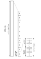
- Fig. 15 illustrates a radio frame configuration of a downlink of LTE. As illustrated in the drawings, the radio frame is stratified into three layers in ascending order of time units: a timeslot (Slot), a Subframe, and a Radio frame.
- the timeslot of a length of 0.5 ms is configured with 7 OFDM symbols (only in a case of normal unicast transmission) and is a unit of a demodulation process when a user (UE terminal) side performs reception.
- the subframe of a length of 1 ms is configured with two consecutive timeslots (14 OFDM symbols) and is a transmission time unit of one data packet subjected to a correction encoding.
- the radio frame of a length of 10 ms is configured with ten consecutive subframes (in other words, 20 timeslots) and is a basic unit for multiplexing of all physical channels.
- the subframe is divided into a control region PDCCH used as a control signal from the eNodeB, and a data region PDSCH portion used as user data.
- RB Resource Block
- a scheduler mounted on the base station assigns radio resources with respect to each user, in units of Resource Blocks.
- a maximum of three OFDM symbols from the beginning of the subframe are used for the control channel, in other words, the PDCCH.
- the scheduler of the base station can perform assignment of the Resource Block to every subframe, that is, at an interval of 1 ms.
- Positional information of the Resource Block is termed scheduling. Both the scheduling information of the uplink and the scheduling information of the downlink are described in the control channel of the downlink. Each user can see the control channel and recognize the Resource Block assigned to him or her.
- the timeslot of the length of 0.5 ms is a minimum unit of assignment available to each user.
- the scheduler mounted on the base station (eNodeB) assigns available timeslots to each user in units of timeslots.
- eNodeB the base station
- the TDD it is possible to select either the uplink or the downlink for use for each subframe.
- CoMP When CoMP is applied to a data communication system that is compliant with LTE, it is important to configure a CoMP set with a necessary minimum number of eNodeBs satisfying the quality necessary for the UE terminal. Further, if considering the movement of the UE terminal, a dynamic point selection that dynamically updates the CoMP set is desirable. When the update of the point selection is performed, it is necessary to consider a decrease in throughput due to a reference signal occupying communication sequences within the system, an increase in the overhead of the uplink due to the feedback of the measurement result of the reference signal by the UE terminal to the eNodeB, and an increase in power consumption of the UE terminal accompanying the measurement of the reference signal and the feedback of the measurement results.
- the reference signal transmitted from the eNodeB includes a CRS, a CSI-RS, and a SRS.
- the measurement of the reference signal can be generally used for various purposes.
- a first purpose includes the UE terminal searching for an eNodeB of a handover destination. When the quality of a Serving eNodeB deteriorates, the UE terminal performs measurement for an eNodeB in an adjacent cell in order to search for an eNodeB of a next handover destination.
- a second purpose includes acquiring the quality of the channel.
- the measurement of the reference signal is performed for determining a value of precoding (a weighting factor of an antenna for performing a beam forming) used on the eNodeB side at the time of transmission in the downlink, or for the scheduler in the eNodeB distributing the radio resources to each UE terminal. Then, obtaining information necessary for the point selection is added as a new object of the measurement of the reference signal. Further, it is considered that the UE terminal feeds back also the measurement results which are a material for determining the CoMP set, in addition of the feedback information of the reference signal.
- precoding a weighting factor of an antenna for performing a beam forming
- a Cell-specific Reference Signal is a reference signal that is inserted into the subframe of the downlink and has existed since Release 8 which is the initial version of LTE.
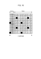
- Fig. 16 illustrates an aspect in which the CRS is inserted into the subframe.
- the first to third OFDM symbols are PDCCHs
- the fourth and subsequent OFDM symbols are PDSCHs.
- the resource element portions filled in black correspond to CRS signals, the CRS is inserted into the region of both the PDCCH and the PDSCH.
- the CRS is transmitted from the eNodeB. That is because it is assumed that the UE terminal always uses the CRS for synchronization acquisition and channel estimation with the eNodeB, quality measurement of the eNodeB, and the like.
- the CRS uses the same location (that is, the same resource element in a frequency direction and a time direction) in each eNodeB (in Fig. 16 , the resource elements filled in black are commonly used as insertion locations of the CRS in each eNodeB). Therefore, it is necessary to ensure that the eNodeBs are orthogonal with each other, and signals having different sequences for the respective eNodeBs are used in the CRS. The number of sequences is 504 in total. If the Cell IDs of the eNodeBs are different, the sequences of the CRS are also different. From the meaning of being specific for each cell, the signals are called Cell-specific Reference Signals.
- CSI-RS Channel State Information Reference Signal
- RRC Radio Resource Control
- the CSI-RS is a reference signal which was newly introduced in Release 10 of 3GPP.
- the CSI-RS is also a signal specific for each cell, and can be referred to as "Cell-specific".
- Cell-specific The locations of the resource elements, to which the CSI-RSs are inserted, in the subframe can be changed by the setting.
- a sequence for improving an orthogonality between eNodeBs is prepared also in the inserted signals.
- the CRS-RS has a great advantage of being able to reduce the overhead occupied by the reference signal. Further, even in the eNodeBs having the same Cell ID, it is possible to assign the CSI-RS in different locations. If the CSI-RS is separately set even in a case in which the same Cell ID is assigned to a plurality of Pico eNodeBs such as the RRHs, as in the case of realizing CoMP by an intensive control scheme, the UE terminal can perform the measurement while distinguishing the respective RRHs. Accordingly, the present inventors contemplate that the CSI-RS is promising as the reference signal for the point selection.
- the Sounding Reference Signal is a reference signal that is included in the subframe of the uplink and has existed since Release 8 of 3GPP.
- the SRS is inserted over all frequency ranges of the last OFDM symbol of 14 OFDM symbols in the corresponding subframe.
- the insertion period of the SRS can be changed from 2 ms to 160 ms.
- the eNodeB acquires a channel state of the uplink based on the SRS and uses the channel state as information for scheduling.
- the SRS is used, it is possible to acquire the channel condition of the uplink with a small overhead.
- the eNodeB is able to use the SRS also in order to obtain the channel condition of the downlink in the case of the TDD.
- Scenario 1 is a scenario that makes cells into sectors and performs CoMP between the sectors.
- scenarios 2 to 4 are scenarios that perform CoMP using the RRH, the RRH performs transmission with great power equivalent to that of the Macro eNodeB in scenario 2, whereas it is assumed that the transmission power of the RRH is small in scenarios 3 to 4.
- the Cell ID of its own is assigned to each RRH in scenario 3, whereas the same Cell ID as that of the Macro eNodeB is assigned to each RRH in scenario 4.
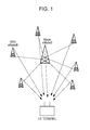
- Fig. 1 schematically illustrates an aspect in which a Macro eNodeB corresponding to scenario 3 and scenario 4 and a plurality of RRHs subordinate thereto are connected.
- the RHHs are disposed as a measure for non-sensing in cell edges.
- the Macro eNodeB and respective RHHs (or a Pico eNodeB) are connected by baseband signals using an X2 interface made from optical fibers, or the like. Then, the Macro eNodeB performs a baseband signal process and control of respective RRHs and collectively performs radio resource control between cells.
- the Macro eNodeB and the RRH transmit and receive data to and from the UE terminal at the same time so as to perform CoMP.
- the Macro eNodeB mainly operates as a Serving eNodeB.
- the respective RRHs have their own Cell IDs and have different sequences of CRS. Accordingly, even if the reference signals are simultaneously transmitted from the respective RRHs, the UE terminal can individually acquire a quality of the respective RRHs. In other words, in scenario 3, it is possible to use the CRS as the reference signal for the point selection.
- scenario 4 the same Cell ID as that of the Macro eNodeB is assigned to the respective RRHs, and the sequence of the CRS is the same. Therefore, the UE terminal cannot individually obtain a quality of the respective RRHs, from the CRSs simultaneously transmitted from the respective RRHs. In other words, in scenario 4, it is difficult to use the CRS in the reference signal for the point selection. Therefore, in scenario 4, the CSI-RS is promising as the reference signal for the point selection.
- the UE terminal side it is necessary for the UE terminal side to individually acquire channel information for each RRH, by assigning the CSI-RS to different locations for each RRH (as described already, even the eNodeB having the same Cell ID is able to assign the CSI-RS to different locations).
- Implicit Feedback In LTE, since Release 8, there have been three types of mode: Implicit Feedback, Explicit Feedback, and SRS-based Feedback, as a feedback scheme at the time of Single User Multiple Input Multiple output (SU-MIMO) communication. Among these, Implicit Feedback is used even in Release 10. Further, Implicit Feedback is determined in CoMP of Release 11 and the MIMO communication in the CoMP for use.
- SU-MIMO Single User Multiple Input Multiple output
- the base station in a codebook which is designed in advance, 16 types of transmission weighting (precoding) such as, for example, V(1), ..., and V(16) are prepared (however, the number i within parentheses of V(i) is an index number of Predetermined Matrix Index (PMI)). If the mobile station receives a reference signal which is precoded with the transmission weighting V(i) from the base station, the mobile station acquires channel information H between the base station and the mobile station.
- precoding transmission weighting
- PMI Predetermined Matrix Index
- the mobile station temporarily determines which reception power HV(1), ..., HV(16) is the greatest, among 16 types of transmission weight vectors V(1), ..., V(16), the mobile station feeds back the index number indicating a transmission weight vector V which is temporarily determined to the base station.
- the base station transmits data using the transmission weighting V corresponding to the index number which is fed back.
- CQI Channel Quality Index
- PMI Predetermined Matrix Index
- RI Rank Indicator
- the CQI is intended to notify a combination of a modulation scheme and a coding rate, and has 16 types.
- the modulation scheme there are three types: a Quadrature Phase Shift keying (QPSK), a 16 Quadrature Amplitude Modulation (QAM), and a 64 QAM.
- the PMI is an index number indicating the desired transmission weight vector V which is described above.
- the RI is an index indicating a rank of a channel, that is, regarding how many spatially independent channels are present.
- the eNodeB determines the precoding for transmission, the modulation scheme, and the coding rate with reference to three types of information of the CQI, the PMI, and the RI which are transmitted from the UE terminal.
- Release 11 although adding information regarding quality from each base station to the feedback information from the mobile station to the base station is considered, the present applicants consider that the above feedback information defined in Release 10 is a base.
- the CQI feedback can be divided into a wideband and a subband (UE Selected).
- the wideband mode is a mode of feeding back the feedback information corresponding to 20 MHz as one piece of information in a case of operation, for example, in a bandwidth of 20 MHz.
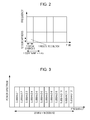
- the subband is a method of use of setting a subband by further binding a bundle of a plurality of Resource Blocks, for example, 12 subcarriers (see Fig. 2 ).
- the subband is a method of use in which 120 subcarriers are set as one band in the frequency direction.
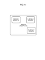
- the UE Selected mode is a mode of individually returning the feedback for the subbands. The feedback is performed for the M best subbands.
- the value of the wideband is also reported (see Fig. 3 ).
- the PMI feedback includes a case without feedback and a case with feedback.
- Table 1 No PMI Single PMI Wideband(wideband COI) Mode 1-0 Mode 1-1 UE Selected (wideband CQI) Mode 2-0 Mode 2-1
- the subband described above is not associated with CoMP and the point selection at all, and relates to feedback in an environment in which CoMP is not performed.
- Means 1-1 for solving the above first problem includes selecting the measurement results to be fed back for determining the CoMP set from the UE terminal such that a set of measurement results of the base station in the wideband is a population and a set of measurement results in the respective subbands is a subset for the population.
- the set of the measurement results with respect to the eNodeBs 1, 2, 3, and 4 is a population.
- the feedback for determining the CoMP set is performed not by selecting the measurement results with respect to all the populations but by selecting only the measurement results with respect to the eNodeBs 1 and 2 which are subsets for the population.
- the wideband is the population and only subsets are fed back independently of the measurement results of the wideband in the subbands. Accordingly, it becomes possible to reduce the feedback amount of the UE terminal.
- both the measurement for the eNodeB which is in use as a transmission point of CoMP and the measurement of the eNodeBs which are candidates of the transmission point are performed.
- the UE terminal returns information for determining which eNodeB is desirable with respect to all the frequencies of the UE terminal in the feedback of the wideband and thus the eNodeB side receiving the feedback is able to ascertain a rough tendency.
- the rough tendency is information indicating which eNodeB is suitable for being added to the CoMP set, with respect to the UE terminal.
- the UE terminal may select only more important information for the respective subbands and feed back the selected information. For example, the measurement results regarding base stations that participate in a current CoMP set in the subband, a base station under consideration to be removed from the CoMP set due to deterioration in quality, a base station under consideration to be newly added to the CoMP set and the like are more important feedback information for the subband.
- the period of the feedback of the wideband from the UE terminal is set to be relatively long, and the period of the feedback of the subband is set to be short.
- Means 1-2 for solving the first problem may include selecting the measurement results to be fed back for determining the CoMP set from the UE terminal so as to include measurement results of base stations other than the set of the measurement results in the respective subbands in addition to the set of the measurement results of the base station in the wideband.
- a certain UE terminal feeds back the measurement results of the wideband with respect to four base stations which are eNodeBs 1, 2, 3, and 4 as the measurement results for determining the CoMP set in the wideband.
- the measurement results are fed back so as to include the eNodeBs 5 and 6 other than the eNodeBs 1, 2, 3 and 4 in the subband 1.
- the measurement results are fed back so as to include the eNodeB 8 other than the eNodeBs 1, 2, 3 and 4 in the subband 2, and it is assumed that the feedback of the measurement results is performed so as to include the eNodeB 7 other than the eNodeBs 1, 2, 3 and 4 in the subband 3 (see Fig. 5 ).
- the measurement result with respect to an eNodeB which is not included in the wideband is fed back in the subband.
- the UE terminal is able to reduce the feedback amount by performing the measurement of an additional eNodeB in the measurement in a part of a band, with respect to the measurement considering all the bands.
- a derived type of the above means 1-2 includes selecting the measurement results to be fed back for determining the CoMP set from the UE terminal so as to include the measurement result of a base station added to the combination of the base stations in the set of the measurement results in the respective subbands, in addition to the set of the measurement results of the base station in the wideband.
- a certain UE terminal feeds back the measurement results of the wideband with respect to four base stations which are the eNodeBs 1, 2, 3, and 4 as the measurement results for determining the CoMP set in the wideband.
- the measurement results are fed back while the eNodeBs 5 and 6 are added to the eNodeBs 1, 2, 3 and 4 in the subband 1.
- the measurement results are fed back while the eNodeB 8 is added to the eNodeBs 1, 2, 3 and 4 in the subband 2
- the measurement results are fed back while the eNodeB 7 is added in the subband 3 (see Fig. 6 ).
- the measurement results, to which the eNodeBs which have not been included in the wideband are added are fed back.
- the priority of the subband to be fed back is determined by the UE terminal or by the base station depending on a situation.
- the priority is determined by the base station, it is assumed that information regarding the determined priority is notified from the base station to the UE terminal.
- the selection of the base station referred to here is both the addition and the removal of a base station included in the CoMP set.
- the addition of a new base station to the CoMP set is determined by feeding back the measurement result of a certain subband, the improvement in reception quality of the UE terminal in the subband is expected.
- the removal of a certain base station from the CoMP set is determined by feeding back the measurement result of a certain subband, the improvement in throughput is expected by suppressing unnecessary radiation from unnecessary base stations.
- the measurement result of the subband having a high possibility of an unnecessary base station being removed from the cooperative group is preferentially selected.
- means 2 for solving the above second problem includes preferentially feeding back the information of a subband having a high possibility of the determination of the addition or removal of the base station being performed on a network side.
- the measurement result of the subband having a high possibility of an improvement in the reception quality by a new base station being added to the CoMP is preferentially selected, and when the feedback is given, the measurement result of the subband having a high possibility of an unnecessary base station being removed from the CoMP set is preferentially selected.
- the UE terminal selects M subbands with higher quality.
- the advantage of feeding back a new measurement result is not derived.
- the measurement result of the subband with good quality does not greatly affect the selection of the base station that performs the CoMP transmission, and thus it is not possible to solve the above second problem.
- the update of the point selection in other words, replacement of base station belonging to the CoMP set
- the CoMP set is not improved and the quality of the subband remains poor.
- Means 2-1 for solving the above second problem includes the UE terminal selecting not M subbands with high quality but M subbands with poor quality. This is because the improvement in quality by the dynamic point selection with respect to the subbands with poor quality is needed the most.
- CoMP is already applied and thus it is assumed that the UE terminal simultaneously receives signals from a plurality of eNodeBs, but this means that the total quality is poor.
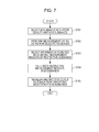
- Fig. 7 illustrates a processing procedure in a form of a flowchart in which the UE terminal feeds back a set of measurement results in a predetermined number of subbands and performs a dynamic point selection based thereon.
- N the number of subbands which are available for use by the UE terminal
- M the number of subbands in which the measurement result is fed back
- the UE terminal selects M subbands with poor quality among N subbands (step S701).
- the UE terminal performs the measurement for the point selection, using the CSI-RSs transmitted from the respective base stations in the M selected subbands (step S702).
- the UE terminal selects information to be fed back, in other words, a base station of which the measurement result is to be fed back, in each of the M selected subbands (step S703). For example, the UE terminal selects the measurement results of the eNodeB which is in use as the transmission point in the current CoMP set and the eNodeB which is the candidate for the transmission point.
- the UE terminal feeds back the measurement results which are selected in step S703 to the Serving eNodeB in each of the M subbands selected in step S701 (step S704).
- the Serving eNodeB side receives the feedback from the UE terminal, it performs the point selection for the M subbands (step S705).
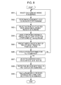
- means 2-1-1 for solving the above second problem includes increasing a priority of a subband for which improvement in quality due to feedback will be to a high degree, and selecting M subbands to be fed back.
- a certain subband has a high expected value of improvement in quality, without necessarily being related to the relative merits of the quality of the subband, by feeding back the measurement result of a new eNodeB and using the new eNodeB for the downlink in the subband (that is, a new base station is added in the CoMP set), the subband is preferentially included in the M subbands.
- Fig. 8 illustrates a processing procedure in a form of a flowchart of performing a dynamic point selection which performs feedback for a predetermined number of subbands which are selected by increasing a priority of a subband with a high degree to which the quality is to be improved by feedback.
- the UE terminal selects one subband among N subbands (step S801).
- the UE terminal performs the measurement for the point selection, using the CSI-RSs transmitted from the respective base stations in the selected subbands (step S802).
- the UE terminal selects information to be fed back, in other words, a base station of which the measurement result is to be fed back, in the selected subbands (step S803).
- the UE terminal feeds back the measurement result of the base station which is selected in step S803, the UE terminal predicts which point selection is to be performed for the subband on the Serving eNodeB side (step S804). Then, the evaluation of the subband is performed by predicting an SINR of reception by the predicted point selection (step S805).
- step S806 If the UE terminal terminates the evaluation for all the N subbands (step S806), it selects M subbands having a great improvement in the SINR (step S807).
- the UE terminal feeds back the measurement result measured in step S802 to the Serving eNodeB, in each of the M selected subbands (step S808).
- the Serving eNodeB side receives the feedback from the UE terminal, it performs the point selection for the M subbands (step S809).
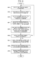
- means 2-1-2 for solving the second problem includes the UE terminal increasing the priority of a subband having high possibility of useless eNodeBs being removed from the CoMP set by the feedback and selecting the M subbands to be fed back.
- the measurement result of the eNodeB in use as the CoMP set is fed back in a specific subband with high quality
- the eNodeB which does not contribute to a significant improvement in the quality has a high possibility of being removed from the CoMP set in the subband. Therefore, the measurement result of the subband, in which the measurement result which is expected to be determined to be removed from the CoMP set can be fed back, should be fed back.
- Fig. 9 illustrates a processing procedure in a form of a flowchart of performing a dynamic point selection which performs feedback for a predetermined number of subbands which are selected by increasing a priority of a subband with a possibility of useless eNodeBs being removed from the CoMP by feedback.
- the UE terminal selects one subband among N subbands (step S901).
- the UE terminal performs the measurement for point selection, using the CSI-RSs transmitted from the respective base stations in the selected subbands (step S902).
- the UE terminal selects information to be fed back, in other words, a base station of which the measurement result is to be fed back, in the selected subbands (step S903).
- the UE terminal feeds back the measurement result of the base station which is selected in step S903, the UE terminal predicts which point selection will be performed for the subband on the Serving eNodeB side (step S904). Then, the evaluation of the subband is performed by evaluating the number of useless eNodeBs to be removed from the CoMP sets by the predicted point selection (step S905).
- step S906 If the UE terminal terminates the evaluation for all the N subbands (step S906), it selects M subbands having a high possibility of the useless eNodeBs being removed from the CoMP set (for example, as a result of the evaluation in step S905, subbands having large number of eNodeBs to be removed from the CoMP set) (step S907).
- the UE terminal feeds back the measurement result measured in step S9802 to the Serving eNodeB, in each of the M selected subbands (step S908).
- the Serving eNodeB side receives the feedback from the UE terminal, it performs point selection for the M subbands (step S909).
- means 2-2 for solving the second problem includes making an assembly of subbands which can be collectively handled, into a subband group (Group of Subbands), performing the measurement for point selection in units of subband groups, and feeding back the measurement results in units of subband groups.
- Fig. 10 illustrates an aspect in which the same CoMP set is consecutive or CoMP sets are consecutive in the subbands which are consecutive in the frequency direction.
- the CoMP sets are formed of three eNodeBs 1, 3, and 5 in any one of the subbands 1 to 5 which are consecutive in the frequency direction, and thus it is possible to make the CoMP sets into the subband group 1.
- the CoMP sets are formed of three eNodeBs 1, 3, and 6 in any one of subbands 6 to 8, it is possible to make the CoMP sets into the subband group 2, whereas since the CoMP sets are formed of three eNodeBs 1, 4, and 6 in any one of subbands 9 to 12, it is possible to make the CoMP sets into the subband group 3. Further, the CoMP sets continuously change between the subband group 1 and the subband group 2 and between the subband group 2 and the subband group 3.
- the UE terminal can reduce a processing amount required for the measurement and an information amount to be fed back by performing the measurement for point selection and the feedback thereof in units of subband groups.
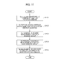
- Fig. 11 illustrates a processing procedure in a flowchart format in which the UE terminal makes the assembly of the subbands which are consecutive in the frequency direction into a group and performs the measurement and the feedback for the point selection in units of subband groups.
- the servicing eNodeB notifies the UE terminal of the CoMP set for the respective subbands (step S1101).
- the UE terminal If the UE terminal receives the notification of the CoMP sets for the respective subbands, it makes the assembly of the subbands belonging to the same CoMP set among the whole N subbands into a subband group (step S1102).
- the UE terminal performs the measurement for point selection for the respective subbands group (step S1103), and performs the feedback of the measurement result to the respective subbands group (step S1104).
- the Serving eNodeB side receives the feedback from the UE terminal, it performs a point selection on M subbands (step S1105) (however, N ⁇ M).
- the UE terminal needs information indicating which eNodeB is currently used to perform CoMP for the respective subbands, in order to perform the feedback of the measurement result for the respective subbands.
- There is a third problem in which if there is no information of the CoMP set for the respective subbands, the UE terminal is not able to select an effective measurement object for the respective subbands. Further, conveying the information of the CoMP set from the Serving eNodeB to the UE terminal using a signal of a downlink leads to a reduction in a throughput of the downlink due to an increase in the overhead due to the control signal.
- Means 3-1 for solving the above third problem includes the Serving eNodeB performing support for selecting an effective measurement object for the respective subbands on the UE terminal side. Specifically, the Serving eNodeB notifies the UE terminal of information for determining a range in which the measurement of point selection for the respective subbands is performed, such as the information regarding the CoMP set for the respective subbands. Since the UE terminal can reduce the processing amount of measurement for point selection for the respective subbands and the information amount to be fed back based on the received information, it is possible to improve the update frequency of point selection while reducing the overhead of the uplink for the point selection, thereby increasing the throughput.
- the Serving eNodeB provides support for the UE terminal selecting the effective measurement object for the respective subbands, by notifying the UE terminal of the information regarding the CoMP set of the respective subbands.
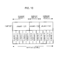
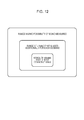
- Means 3-2 for solving the above third problem includes dividing information notified to the UE terminal by the Serving eNodeB into three types of information as illustrated in Fig. 12 : information indicating a range having a possibility of being measured, information indicating a range that is most commonly used, and information indicating a range of the eNodeB that is used additionally for the respective subbands and notifying the divided information so as to reduce the control signal.
- a method of use of the means 3-2 is assumed in which the range having a possibility of being measured is set to have a low update frequency, the most commonly used range is set to have a medium update frequency and the range of the eNodeB additionally used for the respective subbands is set to have a high update frequency.
- the set of eNodeBs that are currently used for the respective subbands (that is, CoMP set) is continuously updated, thereby suppressing an increase in the overhead.
- the Serving eNodeB may notify information regarding the CoMP set for the respective subbands, using the means 3-1 and 3-2, with respect to the UE terminal which performs the means 2-1, 2-1-1, and 2-1-2.
- Fig. 13 illustrates a configuration example of a wireless communication apparatus 1300 which operates as the Serving eNodeB (Macro eNodeB) in the wireless communication system ( Fig. 1 ) according to the present embodiment.
- the illustration of functional modules which perform basic operations as the Macro eNodeB, such as the management of radio resources within the Macro Cell and the transmission of various reference signals is appropriately omitted.
- the wireless communication apparatus 1300 includes an RF communication processing unit 1301 that performs an analog process of wireless signals which are transmitted and received by an antenna and a digital communication processing unit 1302 that performs a modulation process of digital transmission signals and a demodulation process of digital reception signals.
- the digital communication processing unit 1302 exchanges transmission and reception data with a higher layer protocol of a communication layer of the apparatus 1300 to which it belongs. Further, the digital communication processing unit 1302 communicates with other eNodeBs through an X2 interface, a Serving Gateway (S-GW), and a Mobility Management Entity (MME). Further, the digital communication processing unit 1302 performs a baseband signal process and control of each RRH depending on the apparatus 1300 to which it belongs through the X2 interface.
- S-GW Serving Gateway
- MME Mobility Management Entity
- a measurement result holding unit 1303 stores the measurement results of the wideband and the respective subbands which are fed back in the uplink from each UE terminal present within its own cell.
- the CoMP set determination unit 1304 determines the CoMP set of the wideband and the respective subbands for each UE terminal, based on the measurement result of each UE terminal which is stored in the measurement result holding unit 1303.
- a notification unit 1305 notifies the UE terminal of the information regarding the CoMP set for the respective subbands with respect to respective UE terminals which are present within its own cell, the UE terminal performs support for selecting an effective measurement object for the respective subbands.
- the means 3-1 is realized by the notification unit 1305 notifying information for determining a range in which the measurement for the point selection in the respective subbands such as information of the CoMP set for the respective subbands is performed.
- the notification unit 1305 divides information including information notified to the UE terminal into three types of information indicating a range having a possibility of being measured, information indicating a range that is most commonly used, and information indicating a range of the base station that is used additionally for the respective subbands, and notifies the divided information in different update frequency depending on information, thereby realizing the means 3-2.
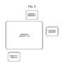
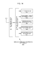
- FIG. 14 schematically illustrates a configuration example of a wireless communication apparatus 1400 that operates as a UE terminal, in the wireless communication system ( Fig. 1 ) according to the present embodiment.
- the illustration of functional modules which perform basic operations as the UE terminal is appropriately omitted.
- the wireless communication apparatus 1400 includes an RF communication processing unit 1401 that performs an analog process of wireless signals which are transmitted and received by an antenna and a digital communication processing unit 1402 that performs a modulation process of digital transmission signals and a demodulation process of digital reception signals.
- the digital communication processing unit 1402 exchanges transmission and reception data with a higher layer protocol of a communication layer of its own apparatus 1400.
- the recognition unit 1403 recognizes a range in which the measurement for point selection is performed in its own apparatus 1400 and information regarding the eNodeB used in the CoMP set for its own apparatus 1400.
- the recognition unit 1403 can basically recognize the information based on the notification from the Serving eNodeB.
- a measurement object determination unit 1404 determines the eNodeB which performs the measurement for the point selection in the respective subbands.
- the measurement object determination unit 1404 basically selects a base station which is in use as a transmission point of the CoMP or is a candidate for the transmission point as a measurement object. Further, when the means 2-1-1 and 2-1-2 are realized, the measurement object determination unit 1404 predicts which CoMP set is to be determined on the Serving eNodeB side by feeding back the measurement result, and selects the eNodeB which is a measurement object. Further, when the means 2-2 is realized, the measurement object determination unit 1404 makes an assembly of subbands which can be collectively handled into a subband group, and determines the subband group as a measurement object.
- a reference signal measurement unit 1405 performs the measurement for point selection, using the CSI-RS from the eNodeB which is selected as a measurement object by the measurement object determination unit 1404, in the respective subbands.
- a measurement result evaluation unit 1406 evaluates the measurement result which is measured by the reference signal measurement unit 1405 for the respective subbands. When the means 2-1-1 is realized, the measurement result evaluation unit 1406 evaluates an expected value of an improvement in an SINR of reception by the predicted point selection. Further, when the means 2-1-2 is realized, the measurement result evaluation unit 1406 evaluates the number of useless eNodeBs to be removed from the CoMP set by the predicted point selection.
- a measurement result selection unit 1407 selects the measurement result to be fed back to the Serving eNodeB, among the measurement results for the respective subbands measured by the reference signal measurement unit 1405. The selected measurement result is transmitted to the Serving eNodeB through the digital communication processing unit 1402 and the RF communication processing unit 1401.
- the measurement result selection unit 1407 selects the measurement result to be fed back for determining the CoMP set such that the set of the measurement results of the base station in the wideband is the population and the set of the measurement results in the respective subbands is a subset for the population.
- the measurement result selection unit 1407 selects the measurement results to be fed back for CoMP set determination, so as to include the measurement results of the base stations other than the set of the measurement results in the respective subbands, in addition to the set of the measurement results of the base stations in the wideband.
- the measurement results to be fed back for determining the CoMP set are selected so as to include the measurement result of the base station which is added to the combination of the base stations of the set of the measurement results in the respective subbands, in addition to the set of the measurement results of the base stations in the wideband.
- the measurement result selection unit 1407 selects the measurement result to be fed back to the Serving eNodeB, based on the result obtained by the measurement result evaluation unit 1406 evaluating the measurement results for the respective subbands, which are measured by the reference signal measurement unit 1405.
- the measurement result selection unit 1407 selects M subbands with poor quality when the means 2-1 is realized. Further, when the means 2-1-1 is realized, the measurement result selection unit 1407 preferentially selects the measurement result of the subband which is evaluated as having a high degree of quality being improved by the feedback by the measurement result evaluation unit 1406.
- the measurement result selection unit 1407 preferentially selects the measurement result of the subband which is evaluated as having a high possibility of useless eNodeBs being removed from the CoMP set by the feedback, by the measurement result evaluation unit 1406.
- the present embodiment when a plurality of subbands obtained by dividing the system frequency are implemented, it is possible to reduce the processing amount measured on the UE terminal side in order to perform the point selection and the information amount to be fed back from the UE terminal to the eNodeB, and thus it is possible to improve the update frequency of point selection while reducing the overhead of the uplink for the point selection, thereby increasing the throughput.
- information for the CoMP determining an effective combination can be transmitted from the UE terminal to the eNodeB without an increase in the overhead, and thus it is possible to improve the update frequency of point selection while reducing the overhead of the uplink for the point selection, thereby increasing the throughput.
Landscapes
- Engineering & Computer Science (AREA)
- Signal Processing (AREA)
- Computer Networks & Wireless Communication (AREA)
- Quality & Reliability (AREA)
- Mobile Radio Communication Systems (AREA)
Applications Claiming Priority (3)
| Application Number | Priority Date | Filing Date | Title |
|---|---|---|---|
| JP2012013746 | 2012-01-26 | ||
| JP2012053542 | 2012-03-09 | ||
| PCT/JP2012/078450 WO2013111412A1 (ja) | 2012-01-26 | 2012-11-02 | 無線通信装置及び無線通信方法、並びに無線通信システム |
Publications (3)
| Publication Number | Publication Date |
|---|---|
| EP2809101A1 true EP2809101A1 (de) | 2014-12-03 |
| EP2809101A4 EP2809101A4 (de) | 2016-01-20 |
| EP2809101B1 EP2809101B1 (de) | 2017-01-04 |
Family
ID=48873154
Family Applications (1)
| Application Number | Title | Priority Date | Filing Date |
|---|---|---|---|
| EP12866795.3A Not-in-force EP2809101B1 (de) | 2012-01-26 | 2012-11-02 | Drahtlose kommunikationsvorrichtung, drahtloses kommunikationsverfahren und drahtloses kommunikationssystem |
Country Status (7)
| Country | Link |
|---|---|
| US (1) | US9571244B2 (de) |
| EP (1) | EP2809101B1 (de) |
| JP (1) | JP5835356B2 (de) |
| CN (1) | CN104081809B (de) |
| BR (1) | BR112014017110A8 (de) |
| RU (1) | RU2014129460A (de) |
| WO (1) | WO2013111412A1 (de) |
Cited By (2)
| Publication number | Priority date | Publication date | Assignee | Title |
|---|---|---|---|---|
| EP3177060A4 (de) * | 2014-08-21 | 2017-07-19 | Huawei Technologies Co., Ltd. | Verfahren und vorrichtung für koordinierte mehrpunktübertragung |
| EP3179797A4 (de) * | 2014-09-05 | 2017-08-23 | Huawei Technologies Co., Ltd. | Datenübertragungsverfahren, -system und -vorrichtung |
Families Citing this family (15)
| Publication number | Priority date | Publication date | Assignee | Title |
|---|---|---|---|---|
| WO2013145489A1 (ja) * | 2012-03-29 | 2013-10-03 | ソニー株式会社 | 無線通信装置及び無線通信方法、並びに無線通信システム |
| KR101706210B1 (ko) * | 2014-02-12 | 2017-02-15 | 한국전자통신연구원 | 기지국 및 그것을 포함하는 통신 시스템, 기지국의 협력 통신 방법 |
| KR102169662B1 (ko) * | 2014-03-10 | 2020-10-23 | 삼성전자주식회사 | 무선 통신 시스템에서 빔 결정 장치 및 방법 |
| EP3175669B1 (de) * | 2014-08-01 | 2019-10-30 | Empire Technology Development LLC | Adaptive kommunikationsressourcenzuweisung in einem drahtlosen netzwerk |
| CN106301613B (zh) * | 2015-05-30 | 2019-04-16 | 北京智谷睿拓技术服务有限公司 | 确定信道质量的方法和装置 |
| CN106301724B (zh) * | 2015-05-30 | 2019-05-07 | 北京智谷睿拓技术服务有限公司 | 传输数据的方法和装置 |
| CN106792887B (zh) * | 2016-12-02 | 2020-12-15 | 惠州Tcl移动通信有限公司 | 一种面向5g平台的节点发现方法及系统 |
| EP3566376B1 (de) * | 2017-01-09 | 2020-10-21 | Motorola Mobility LLC | Verfahren und vorrichtung für einen physikalischen uplink-steuerkanal in ressourcenblöcken |
| CN109391953B (zh) | 2017-08-07 | 2020-06-30 | 维沃移动通信有限公司 | 一种无线链路监测的方法及终端 |
| JP7102767B2 (ja) * | 2018-02-19 | 2022-07-20 | 富士通株式会社 | 送信方法、基地局装置及び無線通信システム |
| US11139939B2 (en) * | 2018-06-08 | 2021-10-05 | Qualcomm Incorporated | Feedback using wideband CSI |
| US11924140B2 (en) * | 2020-10-21 | 2024-03-05 | Qualcomm Incorporated | Subband channel quality information |
| EP4020823A1 (de) * | 2020-12-22 | 2022-06-29 | INTEL Corporation | Verteiltes funkkopfsystem |
| US11729646B2 (en) * | 2020-12-30 | 2023-08-15 | Qualcomm Incorporated | Subband reference signal measurements |
| CN117955582A (zh) * | 2023-04-07 | 2024-04-30 | 中兴通讯股份有限公司 | 数据集发送、接收方法、装置及存储介质 |
Family Cites Families (26)
| Publication number | Priority date | Publication date | Assignee | Title |
|---|---|---|---|---|
| US8948704B2 (en) * | 2008-10-22 | 2015-02-03 | Qualcomm Incorporated | Scope of channel quality reporting region in a multi-carrier system |
| KR101729548B1 (ko) * | 2009-03-06 | 2017-05-02 | 엘지전자 주식회사 | CoMP 기법이 적용된 무선 통신 시스템에서 채널 품질 정보 송신 방법 및 이를 위한 장치 |
| EP2547026B1 (de) * | 2009-03-19 | 2015-08-12 | NEC Corporation | Verbessertes Kanalqualitätsanzeigeverfahren |
| CN101841386B (zh) * | 2009-03-20 | 2014-11-05 | 中兴通讯股份有限公司 | 一种信道质量指示的反馈方法及系统 |
| JP2010258612A (ja) | 2009-04-22 | 2010-11-11 | Sharp Corp | 無線通信システム、基地局装置、制御方法、プログラムおよび記録媒体 |
| KR101618283B1 (ko) * | 2009-05-22 | 2016-05-04 | 삼성전자주식회사 | 통합 다중 포인트 통신을 위한 정보 피드백 방법 |
| CN101997587B (zh) | 2009-08-14 | 2014-11-05 | 中兴通讯股份有限公司 | 多点协作传输中的cqi值确定方法及装置 |
| JP5413964B2 (ja) | 2009-09-14 | 2014-02-12 | パナソニック株式会社 | 無線基地局装置、無線端末装置および無線通信方法 |
| JP5210278B2 (ja) | 2009-10-05 | 2013-06-12 | 株式会社エヌ・ティ・ティ・ドコモ | 無線基地局装置、移動端末装置及び無線通信方法 |
| US8570963B2 (en) * | 2009-10-26 | 2013-10-29 | Qualcomm Incorporated | Coordinated multi-point (CoMP) network and protocol architecture |
| WO2011055940A2 (ko) * | 2009-11-05 | 2011-05-12 | 엘지전자 주식회사 | 채널 품질 정보의 전송 방법 및 이를 위한 장치 |
| US8599708B2 (en) * | 2010-01-14 | 2013-12-03 | Qualcomm Incorporated | Channel feedback based on reference signal |
| CN102196504A (zh) | 2010-03-12 | 2011-09-21 | 株式会社Ntt都科摩 | 协作集配置方法及装置 |
| CN102244567A (zh) * | 2010-05-13 | 2011-11-16 | 清华大学 | 通信控制服务器、基站、终端、联合服务系统及方法 |
| US8964591B2 (en) * | 2010-06-29 | 2015-02-24 | Lg Electronics Inc. | Method and device for transmitting/receiving channel state information in a wireless communication system |
| WO2012094608A2 (en) * | 2011-01-07 | 2012-07-12 | Interdigital Patent Holdings, Inc. | Communicating channel state information (csi) of multiple transmission points |
| US8995400B2 (en) * | 2011-02-11 | 2015-03-31 | Qualcomm Incorporated | Method and apparatus for enabling channel and interference estimations in macro/RRH system |
| US9559820B2 (en) * | 2011-02-18 | 2017-01-31 | Qualcomm Incorporated | Feedback reporting based on channel state information reference signal (CSI-RS) groups |
| US8599711B2 (en) * | 2011-04-08 | 2013-12-03 | Nokia Siemens Networks Oy | Reference signal port discovery involving transmission points |
| US20130021925A1 (en) * | 2011-07-22 | 2013-01-24 | Sharp Laboratories Of America, Inc. | Coordinated multipoint (comp) transmission method selection and feedback requirements |
| US20130083681A1 (en) * | 2011-09-30 | 2013-04-04 | Research In Motion Limited | Methods of Channel State Information Feedback and Transmission in Coordinated Multi-Point Wireless Communications System |
| US9025574B2 (en) * | 2011-08-12 | 2015-05-05 | Blackberry Limited | Methods of channel state information feedback and transmission in coordinated multi-point wireless communications system |
| US9306638B2 (en) * | 2011-08-25 | 2016-04-05 | Qualcomm Incorporated | Backhaul enhancements for cooperative multi-point (CoMP) operations |
| US8797966B2 (en) * | 2011-09-23 | 2014-08-05 | Ofinno Technologies, Llc | Channel state information transmission |
| BR112014011040B1 (pt) * | 2011-11-07 | 2023-03-28 | Motorola Mobility Llc | Método e aparelho para retorno de csi para esquemas de processamento conjunto em um sistema de comunicação de multiplexação com divisão de frequência ortogonal com transmissão de ponto múltiplo coordenado |
| US9537638B2 (en) * | 2012-05-11 | 2017-01-03 | Qualcomm Incorporated | Method and apparatus for performing coordinated multipoint feedback under multiple channel and interference assumptions |
-
2012
- 2012-11-02 JP JP2013555125A patent/JP5835356B2/ja not_active Expired - Fee Related
- 2012-11-02 RU RU2014129460A patent/RU2014129460A/ru not_active Application Discontinuation
- 2012-11-02 EP EP12866795.3A patent/EP2809101B1/de not_active Not-in-force
- 2012-11-02 US US14/372,855 patent/US9571244B2/en not_active Expired - Fee Related
- 2012-11-02 BR BR112014017110A patent/BR112014017110A8/pt not_active Application Discontinuation
- 2012-11-02 WO PCT/JP2012/078450 patent/WO2013111412A1/ja not_active Ceased
- 2012-11-02 CN CN201280067511.4A patent/CN104081809B/zh not_active Expired - Fee Related
Cited By (3)
| Publication number | Priority date | Publication date | Assignee | Title |
|---|---|---|---|---|
| EP3177060A4 (de) * | 2014-08-21 | 2017-07-19 | Huawei Technologies Co., Ltd. | Verfahren und vorrichtung für koordinierte mehrpunktübertragung |
| EP3179797A4 (de) * | 2014-09-05 | 2017-08-23 | Huawei Technologies Co., Ltd. | Datenübertragungsverfahren, -system und -vorrichtung |
| US10432285B2 (en) | 2014-09-05 | 2019-10-01 | Huawei Technologies Co., Ltd. | Data transmission method, system, and device |
Also Published As
| Publication number | Publication date |
|---|---|
| CN104081809A (zh) | 2014-10-01 |
| JPWO2013111412A1 (ja) | 2015-05-11 |
| CN104081809B (zh) | 2018-03-30 |
| US9571244B2 (en) | 2017-02-14 |
| BR112014017110A8 (pt) | 2017-07-04 |
| RU2014129460A (ru) | 2016-02-10 |
| WO2013111412A1 (ja) | 2013-08-01 |
| JP5835356B2 (ja) | 2015-12-24 |
| EP2809101B1 (de) | 2017-01-04 |
| BR112014017110A2 (pt) | 2017-06-13 |
| EP2809101A4 (de) | 2016-01-20 |
| US20150009924A1 (en) | 2015-01-08 |
Similar Documents
| Publication | Publication Date | Title |
|---|---|---|
| EP2809101B1 (de) | Drahtlose kommunikationsvorrichtung, drahtloses kommunikationsverfahren und drahtloses kommunikationssystem | |
| US9438392B2 (en) | Radio communication device, radio communication method, and radio communication system | |
| KR102210990B1 (ko) | 업링크 전력 제어를 위한 방법 및 장치 | |
| JP6951416B2 (ja) | 無線通信システムにおけるチャネル態報告のための方法及びその装置 | |
| JP5924403B2 (ja) | 無線通信装置及び無線通信方法、並びに無線通信システム | |
| KR101629325B1 (ko) | 부분 주파수 재사용 방식을 이용하는 무선 통신 시스템에서 채널 상태를 추정하는 방법 및 이를 이용하는 단말 장치 | |
| JP6683378B2 (ja) | 基準信号を送受信するための方法及び装置 | |
| WO2021217328A1 (en) | Csi reporting techniques for multi-panel full duplex base stations | |
| US20250125843A1 (en) | Methods and apparatuses for port index signaling for non-precoder matrix indicator (pmi) channel state information (csi) feedback | |
| US9319123B2 (en) | Method for receiving reference signal and user equipment, and method for transmitting reference signal and base station | |
| KR20130138698A (ko) | 무선 통신 시스템에서 채널 상태 정보 송수신 방법 및 장치 | |
| CN107743042A (zh) | 一种信道状态反馈的方法及装置 | |
| KR20110011524A (ko) | 다중 입출력 통신 시스템에서 채널측정을 위한 기준신호의 전송 방법 및 그 장치 | |
| JP6219927B2 (ja) | 移動通信システムにおけるチャネル状態情報の送受信方法及び装置 | |
| US10097251B2 (en) | Wireless communication system, method for transmitting information of user equipment, method for receiving information of base station, and user equipment and base station thereof | |
| US10193727B1 (en) | Selective muting of transmission of reference signals to reduce interference in a wireless network | |
| CN103298114A (zh) | 通信系统中上行导频信号的资源配置方法和装置 | |
| JP5774583B2 (ja) | 部分周波数再使用方式を利用する無線通信システムでチャンネル状態を推定する方法及びこれを利用する端末装置 | |
| KR20150091526A (ko) | 동적 멀티포인트 통신 구성 지원 | |
| KR101979728B1 (ko) | 기준신호를 송수신하기 위한 방법 및 장치 | |
| JP5504083B2 (ja) | 無線基地局及び通信制御方法 | |
| JP5508973B2 (ja) | 無線基地局及び通信制御方法 |
Legal Events
| Date | Code | Title | Description |
|---|---|---|---|
| PUAI | Public reference made under article 153(3) epc to a published international application that has entered the european phase |
Free format text: ORIGINAL CODE: 0009012 |
|
| 17P | Request for examination filed |
Effective date: 20140820 |
|
| AK | Designated contracting states |
Kind code of ref document: A1 Designated state(s): AL AT BE BG CH CY CZ DE DK EE ES FI FR GB GR HR HU IE IS IT LI LT LU LV MC MK MT NL NO PL PT RO RS SE SI SK SM TR |
|
| DAX | Request for extension of the european patent (deleted) | ||
| RA4 | Supplementary search report drawn up and despatched (corrected) |
Effective date: 20151222 |
|
| RIC1 | Information provided on ipc code assigned before grant |
Ipc: H04W 24/10 20090101AFI20151216BHEP Ipc: H04L 5/00 20060101ALI20151216BHEP Ipc: H04B 7/06 20060101ALI20151216BHEP Ipc: H04W 72/06 20090101ALI20151216BHEP Ipc: H04B 7/02 20060101ALI20151216BHEP Ipc: H04W 28/16 20090101ALI20151216BHEP |
|
| GRAP | Despatch of communication of intention to grant a patent |
Free format text: ORIGINAL CODE: EPIDOSNIGR1 |
|
| INTG | Intention to grant announced |
Effective date: 20160602 |
|
| GRAS | Grant fee paid |
Free format text: ORIGINAL CODE: EPIDOSNIGR3 |
|
| GRAA | (expected) grant |
Free format text: ORIGINAL CODE: 0009210 |
|
| STAA | Information on the status of an ep patent application or granted ep patent |
Free format text: STATUS: THE PATENT HAS BEEN GRANTED |
|
| AK | Designated contracting states |
Kind code of ref document: B1 Designated state(s): AL AT BE BG CH CY CZ DE DK EE ES FI FR GB GR HR HU IE IS IT LI LT LU LV MC MK MT NL NO PL PT RO RS SE SI SK SM TR |
|
| REG | Reference to a national code |
Ref country code: GB Ref legal event code: FG4D |
|
| REG | Reference to a national code |
Ref country code: CH Ref legal event code: EP |
|
| REG | Reference to a national code |
Ref country code: AT Ref legal event code: REF Ref document number: 860312 Country of ref document: AT Kind code of ref document: T Effective date: 20170115 |
|
| REG | Reference to a national code |
Ref country code: IE Ref legal event code: FG4D Ref country code: NL Ref legal event code: FP |
|
| REG | Reference to a national code |
Ref country code: DE Ref legal event code: R096 Ref document number: 602012027586 Country of ref document: DE |
|
| REG | Reference to a national code |
Ref country code: LT Ref legal event code: MG4D |
|
| REG | Reference to a national code |
Ref country code: AT Ref legal event code: MK05 Ref document number: 860312 Country of ref document: AT Kind code of ref document: T Effective date: 20170104 |
|
| PG25 | Lapsed in a contracting state [announced via postgrant information from national office to epo] |
Ref country code: HR Free format text: LAPSE BECAUSE OF FAILURE TO SUBMIT A TRANSLATION OF THE DESCRIPTION OR TO PAY THE FEE WITHIN THE PRESCRIBED TIME-LIMIT Effective date: 20170104 Ref country code: GR Free format text: LAPSE BECAUSE OF FAILURE TO SUBMIT A TRANSLATION OF THE DESCRIPTION OR TO PAY THE FEE WITHIN THE PRESCRIBED TIME-LIMIT Effective date: 20170405 Ref country code: LT Free format text: LAPSE BECAUSE OF FAILURE TO SUBMIT A TRANSLATION OF THE DESCRIPTION OR TO PAY THE FEE WITHIN THE PRESCRIBED TIME-LIMIT Effective date: 20170104 Ref country code: NO Free format text: LAPSE BECAUSE OF FAILURE TO SUBMIT A TRANSLATION OF THE DESCRIPTION OR TO PAY THE FEE WITHIN THE PRESCRIBED TIME-LIMIT Effective date: 20170404 Ref country code: FI Free format text: LAPSE BECAUSE OF FAILURE TO SUBMIT A TRANSLATION OF THE DESCRIPTION OR TO PAY THE FEE WITHIN THE PRESCRIBED TIME-LIMIT Effective date: 20170104 Ref country code: IS Free format text: LAPSE BECAUSE OF FAILURE TO SUBMIT A TRANSLATION OF THE DESCRIPTION OR TO PAY THE FEE WITHIN THE PRESCRIBED TIME-LIMIT Effective date: 20170504 |
|
| PG25 | Lapsed in a contracting state [announced via postgrant information from national office to epo] |
Ref country code: RS Free format text: LAPSE BECAUSE OF FAILURE TO SUBMIT A TRANSLATION OF THE DESCRIPTION OR TO PAY THE FEE WITHIN THE PRESCRIBED TIME-LIMIT Effective date: 20170104 Ref country code: BG Free format text: LAPSE BECAUSE OF FAILURE TO SUBMIT A TRANSLATION OF THE DESCRIPTION OR TO PAY THE FEE WITHIN THE PRESCRIBED TIME-LIMIT Effective date: 20170404 Ref country code: AT Free format text: LAPSE BECAUSE OF FAILURE TO SUBMIT A TRANSLATION OF THE DESCRIPTION OR TO PAY THE FEE WITHIN THE PRESCRIBED TIME-LIMIT Effective date: 20170104 Ref country code: PT Free format text: LAPSE BECAUSE OF FAILURE TO SUBMIT A TRANSLATION OF THE DESCRIPTION OR TO PAY THE FEE WITHIN THE PRESCRIBED TIME-LIMIT Effective date: 20170504 Ref country code: ES Free format text: LAPSE BECAUSE OF FAILURE TO SUBMIT A TRANSLATION OF THE DESCRIPTION OR TO PAY THE FEE WITHIN THE PRESCRIBED TIME-LIMIT Effective date: 20170104 Ref country code: PL Free format text: LAPSE BECAUSE OF FAILURE TO SUBMIT A TRANSLATION OF THE DESCRIPTION OR TO PAY THE FEE WITHIN THE PRESCRIBED TIME-LIMIT Effective date: 20170104 Ref country code: SE Free format text: LAPSE BECAUSE OF FAILURE TO SUBMIT A TRANSLATION OF THE DESCRIPTION OR TO PAY THE FEE WITHIN THE PRESCRIBED TIME-LIMIT Effective date: 20170104 Ref country code: LV Free format text: LAPSE BECAUSE OF FAILURE TO SUBMIT A TRANSLATION OF THE DESCRIPTION OR TO PAY THE FEE WITHIN THE PRESCRIBED TIME-LIMIT Effective date: 20170104 |
|
| REG | Reference to a national code |
Ref country code: DE Ref legal event code: R097 Ref document number: 602012027586 Country of ref document: DE |
|
| PG25 | Lapsed in a contracting state [announced via postgrant information from national office to epo] |
Ref country code: CZ Free format text: LAPSE BECAUSE OF FAILURE TO SUBMIT A TRANSLATION OF THE DESCRIPTION OR TO PAY THE FEE WITHIN THE PRESCRIBED TIME-LIMIT Effective date: 20170104 Ref country code: EE Free format text: LAPSE BECAUSE OF FAILURE TO SUBMIT A TRANSLATION OF THE DESCRIPTION OR TO PAY THE FEE WITHIN THE PRESCRIBED TIME-LIMIT Effective date: 20170104 Ref country code: IT Free format text: LAPSE BECAUSE OF FAILURE TO SUBMIT A TRANSLATION OF THE DESCRIPTION OR TO PAY THE FEE WITHIN THE PRESCRIBED TIME-LIMIT Effective date: 20170104 Ref country code: SK Free format text: LAPSE BECAUSE OF FAILURE TO SUBMIT A TRANSLATION OF THE DESCRIPTION OR TO PAY THE FEE WITHIN THE PRESCRIBED TIME-LIMIT Effective date: 20170104 Ref country code: RO Free format text: LAPSE BECAUSE OF FAILURE TO SUBMIT A TRANSLATION OF THE DESCRIPTION OR TO PAY THE FEE WITHIN THE PRESCRIBED TIME-LIMIT Effective date: 20170104 |
|
| PLBE | No opposition filed within time limit |
Free format text: ORIGINAL CODE: 0009261 |
|
| STAA | Information on the status of an ep patent application or granted ep patent |
Free format text: STATUS: NO OPPOSITION FILED WITHIN TIME LIMIT |
|
| PG25 | Lapsed in a contracting state [announced via postgrant information from national office to epo] |
Ref country code: SM Free format text: LAPSE BECAUSE OF FAILURE TO SUBMIT A TRANSLATION OF THE DESCRIPTION OR TO PAY THE FEE WITHIN THE PRESCRIBED TIME-LIMIT Effective date: 20170104 Ref country code: DK Free format text: LAPSE BECAUSE OF FAILURE TO SUBMIT A TRANSLATION OF THE DESCRIPTION OR TO PAY THE FEE WITHIN THE PRESCRIBED TIME-LIMIT Effective date: 20170104 |
|
| 26N | No opposition filed |
Effective date: 20171005 |
|
| PG25 | Lapsed in a contracting state [announced via postgrant information from national office to epo] |
Ref country code: SI Free format text: LAPSE BECAUSE OF FAILURE TO SUBMIT A TRANSLATION OF THE DESCRIPTION OR TO PAY THE FEE WITHIN THE PRESCRIBED TIME-LIMIT Effective date: 20170104 |
|
| PG25 | Lapsed in a contracting state [announced via postgrant information from national office to epo] |
Ref country code: MC Free format text: LAPSE BECAUSE OF FAILURE TO SUBMIT A TRANSLATION OF THE DESCRIPTION OR TO PAY THE FEE WITHIN THE PRESCRIBED TIME-LIMIT Effective date: 20170104 |
|
| PG25 | Lapsed in a contracting state [announced via postgrant information from national office to epo] |
Ref country code: LI Free format text: LAPSE BECAUSE OF NON-PAYMENT OF DUE FEES Effective date: 20171130 Ref country code: CH Free format text: LAPSE BECAUSE OF NON-PAYMENT OF DUE FEES Effective date: 20171130 |
|
| PG25 | Lapsed in a contracting state [announced via postgrant information from national office to epo] |
Ref country code: LU Free format text: LAPSE BECAUSE OF NON-PAYMENT OF DUE FEES Effective date: 20171102 |
|
| REG | Reference to a national code |
Ref country code: FR Ref legal event code: ST Effective date: 20180731 Ref country code: BE Ref legal event code: MM Effective date: 20171130 |
|
| REG | Reference to a national code |
Ref country code: IE Ref legal event code: MM4A |
|
| PG25 | Lapsed in a contracting state [announced via postgrant information from national office to epo] |
Ref country code: MT Free format text: LAPSE BECAUSE OF NON-PAYMENT OF DUE FEES Effective date: 20171102 |
|
| PG25 | Lapsed in a contracting state [announced via postgrant information from national office to epo] |
Ref country code: FR Free format text: LAPSE BECAUSE OF NON-PAYMENT OF DUE FEES Effective date: 20171130 Ref country code: IE Free format text: LAPSE BECAUSE OF NON-PAYMENT OF DUE FEES Effective date: 20171102 |
|
| PG25 | Lapsed in a contracting state [announced via postgrant information from national office to epo] |
Ref country code: BE Free format text: LAPSE BECAUSE OF NON-PAYMENT OF DUE FEES Effective date: 20171130 |
|
| PG25 | Lapsed in a contracting state [announced via postgrant information from national office to epo] |
Ref country code: HU Free format text: LAPSE BECAUSE OF FAILURE TO SUBMIT A TRANSLATION OF THE DESCRIPTION OR TO PAY THE FEE WITHIN THE PRESCRIBED TIME-LIMIT; INVALID AB INITIO Effective date: 20121102 |
|
| PG25 | Lapsed in a contracting state [announced via postgrant information from national office to epo] |
Ref country code: CY Free format text: LAPSE BECAUSE OF FAILURE TO SUBMIT A TRANSLATION OF THE DESCRIPTION OR TO PAY THE FEE WITHIN THE PRESCRIBED TIME-LIMIT Effective date: 20170104 |
|
| PG25 | Lapsed in a contracting state [announced via postgrant information from national office to epo] |
Ref country code: MK Free format text: LAPSE BECAUSE OF FAILURE TO SUBMIT A TRANSLATION OF THE DESCRIPTION OR TO PAY THE FEE WITHIN THE PRESCRIBED TIME-LIMIT Effective date: 20170104 |
|
| PGFP | Annual fee paid to national office [announced via postgrant information from national office to epo] |
Ref country code: NL Payment date: 20191120 Year of fee payment: 8 |
|
| PG25 | Lapsed in a contracting state [announced via postgrant information from national office to epo] |
Ref country code: TR Free format text: LAPSE BECAUSE OF FAILURE TO SUBMIT A TRANSLATION OF THE DESCRIPTION OR TO PAY THE FEE WITHIN THE PRESCRIBED TIME-LIMIT Effective date: 20170104 |
|
| PG25 | Lapsed in a contracting state [announced via postgrant information from national office to epo] |
Ref country code: AL Free format text: LAPSE BECAUSE OF FAILURE TO SUBMIT A TRANSLATION OF THE DESCRIPTION OR TO PAY THE FEE WITHIN THE PRESCRIBED TIME-LIMIT Effective date: 20170104 |
|
| REG | Reference to a national code |
Ref country code: NL Ref legal event code: MM Effective date: 20201201 |
|
| PG25 | Lapsed in a contracting state [announced via postgrant information from national office to epo] |
Ref country code: NL Free format text: LAPSE BECAUSE OF NON-PAYMENT OF DUE FEES Effective date: 20201201 |
|
| REG | Reference to a national code |
Ref country code: GB Ref legal event code: 746 Effective date: 20211108 |
|
| PGFP | Annual fee paid to national office [announced via postgrant information from national office to epo] |
Ref country code: GB Payment date: 20211020 Year of fee payment: 10 Ref country code: DE Payment date: 20211020 Year of fee payment: 10 |
|
| REG | Reference to a national code |
Ref country code: DE Ref legal event code: R119 Ref document number: 602012027586 Country of ref document: DE |
|
| GBPC | Gb: european patent ceased through non-payment of renewal fee |
Effective date: 20221102 |
|
| PG25 | Lapsed in a contracting state [announced via postgrant information from national office to epo] |
Ref country code: GB Free format text: LAPSE BECAUSE OF NON-PAYMENT OF DUE FEES Effective date: 20221102 Ref country code: DE Free format text: LAPSE BECAUSE OF NON-PAYMENT OF DUE FEES Effective date: 20230601 |