EP2808974A1 - Verfahren und vorrichtung zur stromversorgung aus einer stromquelle - Google Patents
Verfahren und vorrichtung zur stromversorgung aus einer stromquelle Download PDFInfo
- Publication number
- EP2808974A1 EP2808974A1 EP12874923.1A EP12874923A EP2808974A1 EP 2808974 A1 EP2808974 A1 EP 2808974A1 EP 12874923 A EP12874923 A EP 12874923A EP 2808974 A1 EP2808974 A1 EP 2808974A1
- Authority
- EP
- European Patent Office
- Prior art keywords
- power supply
- module
- power
- camera module
- camera
- Prior art date
- Legal status (The legal status is an assumption and is not a legal conclusion. Google has not performed a legal analysis and makes no representation as to the accuracy of the status listed.)
- Ceased
Links
Images


Classifications
-
- G—PHYSICS
- G06—COMPUTING OR CALCULATING; COUNTING
- G06F—ELECTRIC DIGITAL DATA PROCESSING
- G06F1/00—Details not covered by groups G06F3/00 - G06F13/00 and G06F21/00
- G06F1/26—Power supply means, e.g. regulation thereof
-
- H—ELECTRICITY
- H04—ELECTRIC COMMUNICATION TECHNIQUE
- H04N—PICTORIAL COMMUNICATION, e.g. TELEVISION
- H04N23/00—Cameras or camera modules comprising electronic image sensors; Control thereof
- H04N23/60—Control of cameras or camera modules
- H04N23/65—Control of camera operation in relation to power supply
-
- G—PHYSICS
- G06—COMPUTING OR CALCULATING; COUNTING
- G06F—ELECTRIC DIGITAL DATA PROCESSING
- G06F1/00—Details not covered by groups G06F3/00 - G06F13/00 and G06F21/00
- G06F1/16—Constructional details or arrangements
- G06F1/1613—Constructional details or arrangements for portable computers
- G06F1/1633—Constructional details or arrangements of portable computers not specific to the type of enclosures covered by groups G06F1/1615 - G06F1/1626
- G06F1/1684—Constructional details or arrangements related to integrated I/O peripherals not covered by groups G06F1/1635 - G06F1/1675
- G06F1/1686—Constructional details or arrangements related to integrated I/O peripherals not covered by groups G06F1/1635 - G06F1/1675 the I/O peripheral being an integrated camera
-
- H—ELECTRICITY
- H04—ELECTRIC COMMUNICATION TECHNIQUE
- H04N—PICTORIAL COMMUNICATION, e.g. TELEVISION
- H04N23/00—Cameras or camera modules comprising electronic image sensors; Control thereof
- H04N23/57—Mechanical or electrical details of cameras or camera modules specially adapted for being embedded in other devices
Definitions
- the present invention relates to power management technologies, and in particular, to a power supplying method and apparatus.
- the number of cameras configured on the user equipment gradually grows from one to two.
- the cameras configured on the user equipment both need multiple power supplies to supply power, but because of the development of camera technologies, cameras equipped with different sensors have different power-on sequence requirements for the multiple power supplies they need. Given that a platform resource used by the user equipment is limited and each power supply cannot supply power individually, so for each of the cameras using different sensors, a power supply circuit in a platform needs to be individually designed, so as to match the power-on sequence of each power supply.
- Embodiments of the present invention provide a power supplying method and apparatus, which are configured to adaptively supply power to camera modules of different models used by a user equipment.
- a power supplying apparatus which includes:
- the detection pin group of the camera module includes: a detection pin, an identification resistor and a ground point, where the detection pin is connected to the ground point through the identification resistor; correspondingly, the detection module includes:
- the power supply recognition module is specifically configured to query a storage module according to the recognition signal so as to recognize the type of the camera module, to acquire the power supply information corresponding to the type of the camera module, where the storage module stores correspondence of the recognition signal, the type of the camera module and the power supply information.
- the power supplying apparatus further includes:
- the number of the camera modules connected to the detection module is at least two; the number of the power supply modules is at least two, and each of the power supply modules is connected between the power-on control module and each of the camera modules; correspondingly, the power supplying apparatus further includes:
- a camera module which includes:
- the detection pin group includes:
- a power supplying method which includes:
- the recognizing the type of the camera module according to the recognition signal to determine the power supply information corresponding to the type of the camera module specifically includes:
- the method before the generating the recognition signal according to the detected detection signal on the detection pin group of the camera module, the method further includes:
- the method further includes:
- the power supplying method and apparatus provided by the embodiments of the present invention, by setting the power supplying apparatus in a user equipment, a power supply voltage and a power-on sequence required by the camera module installed on the user equipment is recognized, and power is supplied to the camera module, so as to implement a process of using the same circuit structure to supply power to camera modules of different models used by the user equipment.
- FIG. 1 is a schematic structural diagram of a first embodiment of a power supplying apparatus according to an embodiment of the present invention; as shown in FIG. 1 , the power supplying apparatus 11 in this embodiment includes:
- a camera is usually set in a user equipment, such as a mobile phone and a tablet PC; a sensor used by the camera and other external circuits form the camera module 21 together, where the sensor is configured to perform imaging, and is a core element in the camera module 21; the camera module 21 further includes the detection pin group 201 configured to identify the type of the camera module 21; detection pin groups 201 in camera modules of different types are different.
- the detection module 101 is connected to the detection pin group 201 in the camera module 21, and the detection module 101 generates the recognition signal by detecting the detection signal on the detection pin group 201; detection signals on different detection pin groups 201 are different, so generated recognition signals are different as well.
- the power supply recognition module 102 is connected to the detection module 101, and detects, according to the recognition signal generated by the detection module 101, the type of the camera module 21 corresponding to the recognition signal, thereby determining the power supply information corresponding to this type of camera module 21.
- the sensor used in the camera module 21 can work only when three power supplies including a core power supply, an analog power supply and a digital power supply are turned on at the same time, so the power supply information corresponding to the camera module 21 at least needs to include the power supply voltages of the three power supply units and a power supply time sequence relation of the three power supply units, thereby supplying power to the sensor in the camera module 21, so that the camera module 21 can perform imaging normally.
- the external circuit such as a zoom motor, also needs power supply in addition to the sensor in the camera module 21, the power supply recognition module 102 determines, according to the type of the camera module 21 corresponding to the recognition signal, the power supply voltages and the power supply time sequence of the power supply units required by this type of camera module 21.
- the power-on control module 103 is connected to the power supply recognition module 102 and the power supply module 104; the power supply module 104 is configured to supply power to the camera module 21; the camera module 21 at least needs three power supplies to supply power, so the power supply module 104 at least includes three power supply units, and the power-on control module 103 controls the power supply time sequence relation among the at least three power supply units of the power supply module 104 and the power supply voltage of each power supply unit according to the power supply information determined by the power supply recognition module 102.
- the power supply module 104 supplies power to the camera module 21 by using the at least three power supply units controlled according to the power-on control module 103.
- FIG. 2 is a schematic structural diagram of a second embodiment of a power supplying apparatus according to an embodiment of the present invention
- the detection module 101 may specifically include: a current source 111 and an analog-to-digital conversion unit 112.
- the detection pin group 201 of the camera module 21 includes: a detection pin 211, an identification resistor 212 and a ground point 213.
- the detection pin 211 is connected to the ground point 213 through the identification resistor 212.
- An input end of the current source 111 is connected to the detection pin 211; an input end of the analog-to-digital conversion unit 112 is connected to an output end of the current source 11, and an output end of the analog-to-digital conversion unit 112 is connected to the power supply recognition module 102, and the analog-to-digital conversion unit 112 is configured to generate the recognition signal after performing analog-to-digital conversion on the detection signal.
- the detection pin group 201 of the camera module 21 includes the identification resistor 212, and resistance values of identification resistors 212 in different types of camera modules 21 are different, that is to say, the identification resistors 212 are configured to identify camera modules of different types.
- One end of the identification resistor 212 is connected to the ground point 213, and the other end is connected to the detection pin 211.
- the input end of the current source 111 in the detection module 101 is connected to the detection pin 211; and the current source 111 is configured to generate a detection current, that is, the detection signal of the detection module 101.
- the identification resistor 212 is connected to the ground point 213, the ground point 213 is connected to the ground in the user equipment, a loop is formed among the current source 111, the identification resistor 212 and the ground, and the detection current generated by the current source 111 generates an identification voltage in the loop after passing through the identification resistor 212.
- the identification resistors 212 with different resistance values correspond to different identification voltages.
- the input end of the analog-to-digital conversion unit 112 in the detection module 101 is connected to the output end of the current source 111, so that the analog-to-digital conversion unit 112 is capable of detecting the identification voltage.
- the analog-to-digital conversion unit 112 converts the detected analog identification voltage to a digital identification value, and sends the digital identification value to the power supply recognition module 102, where the digital identification value is the recognition signal.
- the power supply recognition module 102 recognizes the type of the camera module 21 according to the identification value.
- the identification resistor is set in the camera module, the identification voltage is generated by using the current source to pass through the identification resistor, and is converted to a recognizable identification value, so as to detect and recognize the type of the camera module, thereby determining the power supply voltages and the power-on sequences for supplying power to the camera module, and supplying power to the camera module; therefore, a process of adaptively supplying power to camera modules of different models used by the user equipment is implemented.
- the foregoing embodiments are not taken as a limitation on specific structures of the detection pin group 201 and the detection module 101; the detection module 101 only needs to obtain different identification values by detecting different detection pin groups 201, so that the different identification values can be recognized by the power supply recognition module 102.
- the ground point 213 in the detection pin group 201 may further be replaced with a second detection pin; by connecting the detection pin 211 and the second detection pin to the two ends of the current source 111 simultaneously, the detection voltage can also be generated on a loop, and converted to the identification value for the power supply recognition module 102 to recognize afterwards.
- FIG. 3 is a schematic structural diagram of a third embodiment of a power supplying apparatus according to an embodiment of the present invention. As shown in FIG. 3 , on the basis of the power supplying apparatus 11 shown in FIG. 1 , the power supplying apparatus 11 may further include a storage module 105.
- the storage module 105 stores correspondence of a recognition signal, a type of a camera module 21 and power supply information; the power supply recognition module 102 is specifically configured to query the storage module 105 according to the recognition signal so as to recognize the type of the camera module 21, to acquire the power supply information corresponding to the type of the camera module 21.
- the power supplying apparatus 11 further includes the storage module 105; the storage module 105 stores the correspondence of the recognition signal generated by the detection module 101, the type of the camera module 21 and the power supply information.
- the power supply information of the camera module 21 includes the power supply time sequence of the at least three power supply units required by the camera module 21 and the power supply voltage of each power supply unit among the at least three power supply units.
- the power supply recognition module 102 may recognize the type of the camera module 21 and acquire the power supply information required by the camera module 21.
- the storage module 105 may also be implemented as a storage module of a user equipment.
- the camera module used in the user equipment is generally powered by three or four power supplies; power supply voltages required by camera modules of different types are generally several relatively stable voltage values, such as 1. 2 V, 1. 5 V, 1. 8 V and 2. 8 V. Therefore, even through camera modules of different types is set in the user equipment, both the power supply voltages and the power-on sequences required by the camera modules are one of a modest number of relatively stable combinations. Therefore, power supply information of the camera modules may be determined by using a method of setting the storage module to store the correspondence of the recognition signal, the type of the camera module and the power supply information in this embodiment, thereby supplying power to different camera modules.
- FIG. 4 is a schematic structural diagram of a third embodiment of a power supplying apparatus according to an embodiment of the present invention. As shown in FIG. 4 , on the basis of the power supplying apparatus 11 shown in FIG. 3 , the power supplying apparatus 11 may further include an address setting module 106.
- the address setting module 106 is configured to set an address of the power supplying apparatus 11 according to received address setting information.
- the user equipment further includes multiple other apparatuses; different apparatuses are connected by using an inter-integrated circuit (Inter-Intergrated Circuit, I2C) bus, and each apparatus has one I2C address.
- I2C Inter-Intergrated Circuit
- the address setting module 106 is set in the power supplying apparatus 11 to provide multiple optional I2C addresses for the power supplying apparatus 11. If another apparatus in the user equipment occupies a default I2C address of the power supplying apparatus 11, the default I2C address of the power supplying apparatus 11 may be replaced through the address setting module 106, thereby avoiding address conflict with another apparatus in the user equipment.
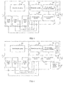
- FIG. 5 is a schematic structural diagram of a fifth embodiment of a power supplying apparatus according to an embodiment of the present invention.
- the power supplying apparatus 11 on the basis of the power supplying apparatus 11 shown in FIG. 1 , if the number of the camera modules 21 is at least two, the number of the power supply modules 104 is at least two, and each power supply module 104 is connected between the power-on control module 103 and a camera module 21; the power supplying apparatus 11 further includes a switching module 107, which is connected to the at least two camera modules 21 and the detection module 101, and configured to make the detection module 101 perform detection on each camera module 21 in preset order.
- two camera modules 21 is set in the user equipment, that is, a primary camera module 31 and a secondary camera module 32, where the primary camera module 31 includes a first detection pin group 301, and the secondary camera module 32 includes a second detection pin group 302.
- the number of the power supply modules 104 is also at least two, that is, a first power supply module 113 and a second power supply module 114; the first power supply module 113 is connected between the power-on control module 103 and the primary camera module 31, and configured to supply power to the primary camera module; the second power supply module 114 is connected between the power-on control module 103 and the secondary camera module 32, and configured to supply power to the secondary camera module.
- the power supplying apparatus 11 further includes a switching module 107, which connects the primary camera module 31 and the secondary camera module 32 to the detection module 101.
- the detection module needs to perform detection on the primary camera module 31 and the secondary camera module 32, so the switching module 107 switches connections between the detection module 101 and the different camera modules, so that the detection module 101 performs detection on each camera module in the preset order.
- the number of the power supply modules 104 in the power supplying apparatus 11 is determined according to the number of the camera modules 21; each power supply module 104 supplies power to one camera module 21; the switching module 107 connects each camera module 21 to the detection module 101, so that the detection module 101 performs detection on each camera module 21.
- the detection module 101 generally performs detection on multiple camera modules 21 according to a preset time-division multiplexing rule, so the switching module 107 also make the detection module 101 switch connections among the multiple camera modules 21 according to the preset time-division multiplexing rule.
- the power supplying apparatus may be implemented by using integrated chip technology.
- the detection module, the power supply recognition module, the power-on control module, the power supply module, the storage module, the address setting module and the switching module may be designed on one integrated chip as required, thereby completing the technical solutions of the power supplying apparatus in the foregoing embodiments.
- the detection module, the power-on control module, the power supply module, the address setting module and the switching module are designed as one power supply chip; the function of the power supply recognition module is fulfilled by using a master chip of the user equipment, and the function of the storage module is fulfilled by using a memory in the user equipment, thereby optimizing the design of the power supply chip.
- one power supply chip is designed for a user equipment using a primary camera and a secondary camera, where a primary camera module needs four power supplies to supply power, and a secondary camera module needs three power supplies to supply power.
- the power supply chip includes a detection module and a switching module; the detection module connects to detection pin groups in the primary and secondary camera modules through the switching module by using two pins of the chip, so as to obtain recognition signals corresponding to the primary and secondary camera modules; the power supply chip sends the detected recognition signals to a master chip of the user equipment through an I2C bus by using two other pins, for the master chip to recognize types of the primary and secondary camera modules and determine power supply information of the primary and secondary cameras; a power-on control module of the power supply chip receives, through the I2C bus, the power supply information of the primary and secondary camera modules sent by the master chip, and controls each power supply unit in the power supply chip to supply power to the primary and secondary camera modules; seven power supply units are set in the power supply chip, where four power supply units are connected to the primary camera
- FIG. 6 is a schematic structural diagram of a first embodiment of a camera module according to an embodiment of the present invention.
- a camera module 61 in this embodiment includes:
- the power supplying apparatus 62 includes any one of the power supplying apparatuses in the embodiments shown in FIG. 1 to FIG. 5 .
- the camera unit 602 includes all modules completing imaging and zooming functions in the camera module 61; except the camera unit 602, none of other units and modules in the camera module 61 needs a power supply to supply power; the number of the power supply units 603 is the same as the number of power supplies required by the camera unit 602. In general, a sensor used for imaging in the camera unit 602 needs three power supplies, and some camera units 602 may further provide a zooming function; a zoom motor used for zooming needs one power supply. Therefore, the number of the power supply units 603 is generally 3 or 4.
- the power supply units 603 are connected to the power supplying apparatus through power pins 604, and receive power supplied by power supply modules in the power supplying apparatus.
- This embodiment enables the power supplying apparatus to detect and recognize a type of a camera modules by setting a detection pin group in the camera modules, thereby determining a power supply voltage and power-on sequence provided for the camera modules, and supplying power to the camera modules.
- FIG. 7 is a schematic structural diagram of a second embodiment of a camera module according to an embodiment of the present invention.
- the detection pin group 601 includes a detection pin 611, an identification resistor 612 and a ground point 613; the detection pin 611 is connected to the ground point 613 through the identification resistor 612.
- the detection pin 611 is configured to connect to the power supplying apparatus; the identification resistor 612 is configured to identify the type of the camera module 61; the ground point 613 is configured for grounding; the detection pin 611 and the ground point 613 provide a current loop for the power supplying apparatus to detect the type of the camera module 61.
- the detection pin 611, the ground point 613 and the power pin 604 may be set in one connector together, so as to serve as pins of the connector; the camera module 61 is installed in a user equipment through the connector, and connected to another apparatus in the user equipment through each pin, thereby completing power supplying and recognition of the camera module 61.
- the camera module 61 may further complete data transmission with other apparatuses in the user equipment through the pins in the connector.
- the camera module 61 of this embodiment is the same as the camera module 21 in the embodiment shown in FIG. 2 in terms of structure and function, but the details are not described here again.
- the detection pin group in the camera module may have multiple implementation manners; the number of the detection pins may be one or more, for example, the number of the detection pins is two, one identification resistor may be connected between the two detection pins, and identification resistors with different resistance values may identify the types of the camera modules.
- the detection module of the power supplying apparatus may be a circuit structure capable of correspondingly detecting different detection signals generated by the identification resistors. For example, one end of a current source may be connected to one detection pin, and the other end of the current source may be connected to the ground point and another detection pin, and then detects potentials generated by the identification resistors, thereby obtaining recognition signals after analog-to-digital conversion. This embodiment is not taken as a limitation of implementation manners of the camera module and the detection module.
- FIG. 8 is a flowchart of a first embodiment of a power supplying method according to an embodiment of the present invention. As shown in FIG. 8 , the method includes:
- the method of this embodiment is used to implement the technical solution of the apparatus embodiment shown in FIG. 1 , and has a similar implementation principle and technical effect, but the details are not described here again.
- FIG. 9 is a flowchart of a second embodiment of a power supplying method according to an embodiment of the present invention. As shown in FIG. 9 , the method includes:
- the method of this embodiment is used to implement the technical solution of the apparatus embodiment shown in FIG. 3 , and has a similar implementation principle and technical effect, but the details are not described here again.
- the power supplying method of the present invention further includes: setting an address according to received address setting information. It is used to avoid address conflict between the power supplying apparatus and another apparatuses in a user equipment at the same time of implementing adaptive power supplying to camera modules of different models used by the user equipment.
- the user equipment usually has two camera modules, so in the method embodiments shown in FIG. 8 and FIG. 9 , if the number of the detected camera modules is at least two, detection is performed on each camera module in preset order, and after obtaining the type of each camera module by detecting, the power supply module is used to supply power to each camera module.
Landscapes
- Engineering & Computer Science (AREA)
- Theoretical Computer Science (AREA)
- Physics & Mathematics (AREA)
- General Engineering & Computer Science (AREA)
- General Physics & Mathematics (AREA)
- Computer Hardware Design (AREA)
- Multimedia (AREA)
- Signal Processing (AREA)
- Human Computer Interaction (AREA)
- Studio Devices (AREA)
Applications Claiming Priority (1)
| Application Number | Priority Date | Filing Date | Title |
|---|---|---|---|
| PCT/CN2012/087159 WO2014094295A1 (zh) | 2012-12-21 | 2012-12-21 | 电源供电方法及装置 |
Publications (2)
| Publication Number | Publication Date |
|---|---|
| EP2808974A1 true EP2808974A1 (de) | 2014-12-03 |
| EP2808974A4 EP2808974A4 (de) | 2015-03-11 |
Family
ID=50086348
Family Applications (1)
| Application Number | Title | Priority Date | Filing Date |
|---|---|---|---|
| EP12874923.1A Ceased EP2808974A4 (de) | 2012-12-21 | 2012-12-21 | Verfahren und vorrichtung zur stromversorgung aus einer stromquelle |
Country Status (4)
| Country | Link |
|---|---|
| US (1) | US9402027B2 (de) |
| EP (1) | EP2808974A4 (de) |
| CN (1) | CN103596634B (de) |
| WO (1) | WO2014094295A1 (de) |
Cited By (2)
| Publication number | Priority date | Publication date | Assignee | Title |
|---|---|---|---|---|
| CN105807641A (zh) * | 2014-12-29 | 2016-07-27 | 联想(北京)有限公司 | 一种控制方法及电子设备 |
| CN109683693A (zh) * | 2018-11-20 | 2019-04-26 | 北京计算机技术及应用研究所 | 一种输出时序自适应控制的计算机电源 |
Families Citing this family (20)
| Publication number | Priority date | Publication date | Assignee | Title |
|---|---|---|---|---|
| CN105409055A (zh) * | 2014-05-19 | 2016-03-16 | 华为技术有限公司 | 一种电池及电路 |
| CN106055044B (zh) * | 2016-05-30 | 2019-06-07 | 维沃移动通信有限公司 | 一种兼容识别不同型号传感器的方法和终端 |
| CN109766298B (zh) * | 2016-07-19 | 2023-03-31 | 海信视像科技股份有限公司 | 基于USB Type-C接口的终端设备、外接设备及供电系统 |
| CN106844129B (zh) * | 2016-11-18 | 2019-06-11 | 深圳市新国都支付技术有限公司 | 一种pos机自动开关机检测装置 |
| CN106993182A (zh) * | 2017-03-17 | 2017-07-28 | 惠州凯珑光电有限公司 | 一种双摄像头检测装置、系统及方法 |
| KR101886361B1 (ko) * | 2017-05-26 | 2018-08-09 | 주식회사 동운아나텍 | 액츄에이터 이동감지 소자의 슬레이브 식별정보 설정방법 |
| CN107395955A (zh) * | 2017-06-14 | 2017-11-24 | 广东小天才科技有限公司 | 一种确定摄像头模块上电时序的方法及用户终端 |
| CN107749949B (zh) * | 2017-11-02 | 2020-08-18 | 奇酷互联网络科技(深圳)有限公司 | 摄像头自适应方法、摄像头自适应装置和电子设备 |
| CN107948526A (zh) * | 2017-12-26 | 2018-04-20 | 北京传嘉科技有限公司 | 摄像头的驱动处理方法和装置 |
| CN108170211B (zh) * | 2017-12-27 | 2021-04-06 | 上海传英信息技术有限公司 | 摄像头上电驱动方法与电子终端 |
| US10904423B2 (en) * | 2018-03-16 | 2021-01-26 | Hanwha Techwin Co., Ltd. | Image providing apparatus and method |
| US11163348B2 (en) * | 2018-05-03 | 2021-11-02 | Samsung Electronics Co., Ltd. | Connectors that connect a storage device and power supply control device, and related power supply control devices and host interface devices |
| CN108828383A (zh) * | 2018-08-13 | 2018-11-16 | 深圳市亚派光电器件有限公司 | 光电元件测试系统及方法 |
| CN109375089A (zh) * | 2018-09-04 | 2019-02-22 | 视联动力信息技术股份有限公司 | 一种电源的切换方法和装置 |
| CN110823579B (zh) * | 2019-11-11 | 2021-08-17 | 西安航天动力试验技术研究所 | 发动机试验台缓变参数采集系统的传感器信号切换装置 |
| CN111246112B (zh) * | 2020-03-04 | 2021-03-23 | 维沃移动通信有限公司 | 摄像头模组的供电电路、供电方法以及电子设备 |
| CN213043743U (zh) * | 2020-08-31 | 2021-04-23 | 上海商汤临港智能科技有限公司 | 摄像模组 |
| CN112821504B (zh) * | 2021-02-01 | 2021-09-14 | 深圳市南霸科技有限公司 | 一种应急启动电源 |
| CN113834132A (zh) * | 2021-09-26 | 2021-12-24 | 佛山市顺德区美的电子科技有限公司 | 空调器滤网模块的供电方法、控制装置及空调器 |
| CN119676551A (zh) * | 2024-12-17 | 2025-03-21 | 信利光电股份有限公司 | 一种兼容性高的摄像头模组pmic及其供电方法 |
Family Cites Families (15)
| Publication number | Priority date | Publication date | Assignee | Title |
|---|---|---|---|---|
| US4737812A (en) * | 1985-08-05 | 1988-04-12 | Nippon Kogaku K.K. | Automatic focusing camera |
| JP3382973B2 (ja) * | 1992-02-07 | 2003-03-04 | オリンパス光学工業株式会社 | 電子内視鏡装置 |
| EP0669756B1 (de) * | 1994-02-23 | 2001-10-17 | Smith & Nephew, Inc. | Kamerakopf mit Speicher |
| JP3342261B2 (ja) * | 1995-09-25 | 2002-11-05 | キヤノン株式会社 | 電子機器 |
| FR2760163A1 (fr) * | 1997-02-25 | 1998-08-28 | Philips Electronics Nv | Appareil de telecommunication muni d'un dispositif de reconnaissance de peripheriques |
| US6396169B1 (en) * | 2000-02-29 | 2002-05-28 | 3Com Corporation | Intelligent power supply control for electronic systems requiring multiple voltages |
| US6738574B2 (en) * | 2002-01-31 | 2004-05-18 | Olympus Optical Co., Ltd. | Camera system and accessory device |
| US20050268000A1 (en) * | 2004-05-28 | 2005-12-01 | Carlson Mark J | Accessory identifier in an electronic device |
| CN101432674A (zh) * | 2006-04-25 | 2009-05-13 | 德克萨斯仪器股份有限公司 | 内置集成电路寻址的方法及用于执行该方法的装置 |
| US7587539B2 (en) * | 2006-04-25 | 2009-09-08 | Texas Instruments Incorporated | Methods of inter-integrated circuit addressing and devices for performing the same |
| CN101163162A (zh) * | 2006-10-11 | 2008-04-16 | 上海晨兴电子科技有限公司 | 具有自动识别摄像头类型的手机 |
| JP2008160933A (ja) * | 2006-12-21 | 2008-07-10 | Sharp Corp | チョッパレギュレータ回路 |
| JP4983735B2 (ja) * | 2008-06-26 | 2012-07-25 | ミツミ電機株式会社 | 電源制御用半導体集積回路 |
| CN101835301A (zh) * | 2009-03-11 | 2010-09-15 | 上海创波光电科技有限公司 | 应用记忆芯片进行自动识别led负载光源的方法和实现装置 |
| US9229833B2 (en) * | 2011-01-28 | 2016-01-05 | Fairchild Semiconductor Corporation | Successive approximation resistor detection |
-
2012
- 2012-12-21 CN CN201280014446.9A patent/CN103596634B/zh active Active
- 2012-12-21 EP EP12874923.1A patent/EP2808974A4/de not_active Ceased
- 2012-12-21 WO PCT/CN2012/087159 patent/WO2014094295A1/zh not_active Ceased
-
2013
- 2013-11-22 US US14/087,574 patent/US9402027B2/en active Active
Cited By (4)
| Publication number | Priority date | Publication date | Assignee | Title |
|---|---|---|---|---|
| CN105807641A (zh) * | 2014-12-29 | 2016-07-27 | 联想(北京)有限公司 | 一种控制方法及电子设备 |
| CN105807641B (zh) * | 2014-12-29 | 2018-12-14 | 联想(北京)有限公司 | 一种控制方法及电子设备 |
| CN109683693A (zh) * | 2018-11-20 | 2019-04-26 | 北京计算机技术及应用研究所 | 一种输出时序自适应控制的计算机电源 |
| CN109683693B (zh) * | 2018-11-20 | 2021-03-19 | 北京计算机技术及应用研究所 | 一种输出时序自适应控制的计算机电源 |
Also Published As
| Publication number | Publication date |
|---|---|
| CN103596634A (zh) | 2014-02-19 |
| US9402027B2 (en) | 2016-07-26 |
| EP2808974A4 (de) | 2015-03-11 |
| US20140176790A1 (en) | 2014-06-26 |
| WO2014094295A1 (zh) | 2014-06-26 |
| CN103596634B (zh) | 2017-06-20 |
Similar Documents
| Publication | Publication Date | Title |
|---|---|---|
| US9402027B2 (en) | Power supplying method and apparatus | |
| US8773078B2 (en) | Universal serial bus (USB) charging system and method thereof | |
| CN109768599B (zh) | 一种基于多usb-c接口的充电方法及主设备 | |
| JP6740430B2 (ja) | 電子機器、カメラ、電力供給システム、及び電力供給方法 | |
| EP3330835A1 (de) | Netzteil, endgerätevorrichtung, ladesystem und ladeverfahren | |
| KR20210014356A (ko) | Usb 장치의 손상을 방지하기 위한 전자 장치 및 그의 동작 방법 | |
| KR20210045912A (ko) | 공진형 충전 회로를 포함하는 전자 장치 | |
| US9411771B2 (en) | Server system for switching master and slave devices | |
| US20140223236A1 (en) | Device for testing a graphics card | |
| JP2018013932A (ja) | 電子機器 | |
| US20150185817A1 (en) | Charging circuit for usb interface | |
| CN107181290B (zh) | 电池管理系统 | |
| WO2023008724A1 (ko) | 전자 장치 및 전자 장치의 동작 방법 | |
| CN109189144A (zh) | 电源电压的控制方法及装置、系统 | |
| US10775825B2 (en) | Adapter cable, adapter module, and method of operating the same | |
| KR102392278B1 (ko) | 전원 공급 장치, 디바이스 및 아답터의 출력 제어 방법 | |
| CN104868509B (zh) | 一种控制方法及外置电池 | |
| JP6555732B2 (ja) | 蓄電池管理装置及び蓄電池管理方法 | |
| KR20200052131A (ko) | 슬레이브 모듈 | |
| CN112327690B (zh) | 多模块物理地址采样系统 | |
| CN105652760B (zh) | 单片机的电源保护系统及方法 | |
| KR101522294B1 (ko) | 유에스비 포트를 이용한 제조사별 스마트폰 충전 장치 | |
| US20230093533A1 (en) | Charging device and charging system based on master-slave relationship | |
| TWI631747B (zh) | 電能管理系統 | |
| KR101229114B1 (ko) | 범용모듈 |
Legal Events
| Date | Code | Title | Description |
|---|---|---|---|
| PUAI | Public reference made under article 153(3) epc to a published international application that has entered the european phase |
Free format text: ORIGINAL CODE: 0009012 |
|
| 17P | Request for examination filed |
Effective date: 20131025 |
|
| AK | Designated contracting states |
Kind code of ref document: A1 Designated state(s): AL AT BE BG CH CY CZ DE DK EE ES FI FR GB GR HR HU IE IS IT LI LT LU LV MC MK MT NL NO PL PT RO RS SE SI SK SM TR |
|
| A4 | Supplementary search report drawn up and despatched |
Effective date: 20150206 |
|
| RIC1 | Information provided on ipc code assigned before grant |
Ipc: G06F 1/26 20060101ALI20150202BHEP Ipc: H02M 3/00 20060101ALI20150202BHEP Ipc: H04M 5/14 20060101ALI20150202BHEP Ipc: H02J 7/00 20060101AFI20150202BHEP Ipc: H02M 7/00 20060101ALI20150202BHEP |
|
| DAX | Request for extension of the european patent (deleted) | ||
| 17Q | First examination report despatched |
Effective date: 20160824 |
|
| STAA | Information on the status of an ep patent application or granted ep patent |
Free format text: STATUS: EXAMINATION IS IN PROGRESS |
|
| RAP1 | Party data changed (applicant data changed or rights of an application transferred) |
Owner name: HUAWEI DEVICE (DONGGUAN) CO., LTD. |
|
| REG | Reference to a national code |
Ref country code: DE Ref legal event code: R003 |
|
| STAA | Information on the status of an ep patent application or granted ep patent |
Free format text: STATUS: THE APPLICATION HAS BEEN REFUSED |
|
| 18R | Application refused |
Effective date: 20181130 |