EP2808751A1 - Druckminderer mit Absperrventil - Google Patents
Druckminderer mit Absperrventil Download PDFInfo
- Publication number
- EP2808751A1 EP2808751A1 EP13169842.5A EP13169842A EP2808751A1 EP 2808751 A1 EP2808751 A1 EP 2808751A1 EP 13169842 A EP13169842 A EP 13169842A EP 2808751 A1 EP2808751 A1 EP 2808751A1
- Authority
- EP
- European Patent Office
- Prior art keywords
- shut
- pressure reducing
- print cartridge
- valve
- reducing device
- Prior art date
- Legal status (The legal status is an assumption and is not a legal conclusion. Google has not performed a legal analysis and makes no representation as to the accuracy of the status listed.)
- Granted
Links
Images


Classifications
-
- G—PHYSICS
- G05—CONTROLLING; REGULATING
- G05D—SYSTEMS FOR CONTROLLING OR REGULATING NON-ELECTRIC VARIABLES
- G05D16/00—Control of fluid pressure
- G05D16/04—Control of fluid pressure without auxiliary power
- G05D16/06—Control of fluid pressure without auxiliary power the sensing element being a flexible membrane, yielding to pressure, e.g. diaphragm, bellows, capsule
- G05D16/063—Control of fluid pressure without auxiliary power the sensing element being a flexible membrane, yielding to pressure, e.g. diaphragm, bellows, capsule the sensing element being a membrane
- G05D16/0644—Control of fluid pressure without auxiliary power the sensing element being a flexible membrane, yielding to pressure, e.g. diaphragm, bellows, capsule the sensing element being a membrane the membrane acting directly on the obturator
- G05D16/0655—Control of fluid pressure without auxiliary power the sensing element being a flexible membrane, yielding to pressure, e.g. diaphragm, bellows, capsule the sensing element being a membrane the membrane acting directly on the obturator using one spring-loaded membrane
-
- G—PHYSICS
- G05—CONTROLLING; REGULATING
- G05D—SYSTEMS FOR CONTROLLING OR REGULATING NON-ELECTRIC VARIABLES
- G05D16/00—Control of fluid pressure
- G05D16/04—Control of fluid pressure without auxiliary power
- G05D16/0402—Control of fluid pressure without auxiliary power with two or more controllers mounted in series
Definitions
- the invention relates to a pressure reducing device for liquid and gaseous media, comprising a housing with an inlet and outlet, a shut-off device and a print cartridge containing a cartridge housing, a slide sleeve, a slide, a base plate and a valve device consisting of a valve seat which is arranged on the slider and a seal which is arranged on the base disc.
- Pressure reducing valves are mainly installed in domestic and industrial water supply pipes, but other applications such as compressed air nets etc. are known. They have the function to reduce the higher pressure in the primary side distribution network to an optimum pressure for the secondary side streamline high pressures are protected. In addition, the noise in the consumer string is reduced and the water consumption is reduced.
- the DE 26 01 349 discloses a valve assembly in which it is possible to provide in a valve housing a shut-off device and a pressure reducing valve. Whereby the arrangement of the two valves takes place side by side and By installing the flush-mounted, a large hole for the accessibility of the valve is provided.
- shut-off device and the print cartridge are arranged coaxially, wherein in the open state of the pressure reducing device, the medium first flows through the shut-off device and then the valve means of the print cartridge.
- the shut-off device is arranged coaxially or concentrically below the print cartridge in the housing of the pressure reducing device and is therefore located on the same central axis.
- the shut-off device has a spring and a cone.
- the spring is arranged in a spring plate which positions the spring in the housing.
- the medium flows through the inlet of the valve in the direction of the shut-off device, which must be actuated so that it is open or the cone must be actively pressed against the spring. This allows the passage through. If the shut-off device is not actuated, the pressure reducing device is closed and the medium can not flow through. The actuation takes place by means of an actuating element, thereby the spring is compressed over the cone and the shut-off device is opened.
- the print cartridge or the sliding sleeve arranged thereon serves to press the spring together over the cone and thereby open the valve.
- the print cartridge is removed from the pressure reducing device, since such a pressure test should take place without pressure reduction unit, and mounted in its place a bypass plug to operate the shut-off device. This then takes over the compression of the spring and allows the flow of the medium.
- the print cartridge In normal operation, the print cartridge is mounted in the housing and pushes, as already described above, the spring together to open the shut-off device.
- the print cartridge corresponds to a known from the prior art cartridge, which is suitable for the use of conventional pressure reducing valves, on the exact operation of this cartridge is referred to in the embodiments.
- the print cartridge is screwed into the housing until the cartridge with its shoulder on the socket, thereby ensuring that the shut-off device is open.
- This type of shut-off is used exclusively for the complete opening or the complete closure, an intermediate position is not provided.
- the inflowing medium flows between the cone, on which preferably a vulcanized seal is located, and the sleeve, which is arranged in the housing. When closed, the seal seals against the bushing in which the plug is pressed against the bushing via the spring and thereby locks or closes the valve.
- a direct pressing of the seal would be conceivable to the housing, which would also achieve the desired sealing effect.
- the print cartridge is screwed into the socket to the stop, of course, alternative connection options such as quick-release are also conceivable.
- the seals located on the cartridge housing seal the system.
- a plurality of seals are arranged on the cartridge housing and are located at different diameters.
- the medium flows through the sliding sleeve, which is preferably a sleeve which has large openings and is surrounded by a mesh which serves as a filter. Thereupon it enters the slide and flows through the valve device, which is formed by the valve seat on the slide and the seal on the base plate.
- the safety sleeve is preferably made of plastic and is hacked into the groove in the housing. This is possible by the flexible shape of the safety sleeve. The cone with the grooves extending therein can be compressed so that the safety sleeve is retractable into the inner diameter of the housing and then propagates again in the groove and thereby in the groove locks.
- the shoulder of the safety sleeve serves as a limitation of the print cartridge when unscrewing, so that the cartridge can not be unscrewed so far that they could fall out but still so far that certainly the spring of the shut-off device is no longer pressed together and the valve or the pressure reducing device is blocked by the shut-off device.
- the stop formed by the shoulder of the safety sleeve is important here.
- the further design of the safety sleeve is used for easy installation, which can be carried out by means of a simple tool such as a pipe or a sleeve.
- a simple safety ring can be used as a stroke limiter, the assembly is not comfortable due to the need of assembly tool and poor accessibility in the flush-mounted installation.
- the pressure reducing device is mainly used in flush installations but can also be installed in visible pipelines.
- the print cartridge If the print cartridge is defective, it can easily be changed. To do this, remove the safety sleeve, which limits the stroke of the print cartridge. This allows unscrewing the print cartridge.
- the print cartridge has a left-hand thread, which serves to screw in and out of the cartridge into the housing, since the lid, which closes the print cartridge housing has a right-hand thread. This ensures that when unscrewing the cartridge, the entire cartridge is unscrewed and not only the lid, which could otherwise result in erroneously assuming that the entire cartridge is present at the shoulder of the safety sleeve and thus would mean that the Barring would be done. However, only the lid was turned out and the barrier is still open and the line is still flowed through with the medium. Of course, a reverse right-hand thread arrangement with respect to the housing and the print cartridge and the lid is possible.
- the pressure reducing device 1 has a housing 8, which is preferably made of gunmetal. Arranged therein is a shut-off device 2, which serves the complete shut-off of the pressure reducing device 1.
- the shut-off device 2 has a spring plate 5, a spring 4, a cone 3 and a seal 6 arranged on the cone 3.
- Arranged in the housing 8 is also a bush 7, which on the one hand serves to receive the print cartridge 9 and to form the sealing geometry for the shut-off device 2.
- the bush 7 is screwed into the housing 7.
- a seal 23 is arranged on the bush 7, preferably an O-ring.
- the bush 7 and the spring plate 5 form a unit and can be made from the same blank.
- the pressure reducing device 1 further includes a printer cartridge 9, which is known from the prior art, which is responsible for the pressure control on the secondary side or in the consumer strand.
- the print cartridge 9 and the shut-off device 2 arranged underneath lie on the same central axis 36 or are arranged coaxially, whereby a compact design is achieved.
- the print cartridge 9 includes a print cartridge housing 18, which is formed from a lower part 19 and a lid 20. Preferably, the two parts are connected by a thread.
- the print cartridge 9 has a sliding sleeve 10.
- the slide sleeve 10 has larger recesses, which allow the medium to flow into the side of the print cartridge 9.
- the sliding sleeve 10 is surrounded by a mesh which serves as a filter.
- the print cartridge 9 has an assembly which is composed of a membrane cover 24, a nut 25, a support plate 26, a base plate 15, a seal 13, a slider 14, spacers 27 and a diaphragm 29.
- the arrangement of the slider 14 to the seal 13 forms the valve seat 12, which is opened and closed by the movement of the slider 14.
- the slider 14 is fixed by the spacer elements 27 me the carrier plate 26 and objected, wherein the distance between the two parts by means of a sleeve 28 is realized on the spacer elements 27.
- the base plate 15 is arranged, which has openings through which the spacer elements 27 protrude, also serve the openings as a passage for the medium.
- the diaphragm 29 is located between the diaphragm cover 24 and support plate 26. The medium flowing through the inlet 16 of the pressure reducing device 1, flows past the open shut-off device 2 through the slide sleeve 10 into the slide 14.
- the valve device 11 is closed when the valve seat 12 through the Seal 13 is covered, which takes place when the pressure on the secondary side and in the extended valve chamber 22 above the set value of, for example, 3 bar.
- the secondary-side medium pressure acts through the openings in the base disk 15 on the underside of the diaphragm 29.
- the diaphragm 29 is thereby pushed up and pulls the slider 14, which is connected via the spacer elements 27 with the support plate 26 upwards, whereby the valve seat 12 closes by the slide 14 is present at the seal 13.
- the desired pressure on the secondary side is achieved by adjusting the spring 30 by means of the adjusting screw 31.
- the diaphragm 29 lowers, whereby the slider 14 is lowered and the valve device 11 is opened by lowering the slider 14 by the valve seat 12 is no longer at the seal 13 is present.
- the seals 32, 33 seal the chambers from each other.
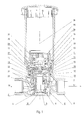
- Fig. 1 the pressure reducing device 1 is shown in normal operation.
- the medium can flow in through the inlet 16 past the shut-off device 2 and is then regulated by the print cartridge 9 at the corresponding pressure for the secondary side.
- the print cartridge 9 is mounted on stop the socket 7 as in Fig. 1 can be seen, which is achieved by screwing into the housing 8 preferably by means of left-hand thread.
- the slide sleeve 10 which acts as an actuator pushes the shut-off device 2 and the spring 4 together via the cone 3 and thus allows the medium to flow through the slide sleeve 10. Then follows, as already described above control process of the print cartridge 9 to control the pressure secondary side.
- Fig. 2 shows the pressure reducing device 1 with closed shut-off device 2.
- the print cartridge 9 was screwed out until it stops by the Safety sleeve 34 is formed, as in Fig. 2 recognizable. This serves to ensure that the cartridge 9 has been screwed far enough out so that the shut-off device 2 is no longer actuated with certainty and thus the spring 4 presses the cone 3 with the seal 6 arranged thereon against the bush 7 and thereby blocks the passage ,
- the sleeve When dismantling the print cartridge 9, the sleeve can be compressed and removed by the flexible or elastic construction of the safety sleeve 34, and then the cartridge are unscrewed. The termination device 2 is then locked. After installation of the new cartridge 9, the safety sleeve 34 can be re-installed in the same way by being compressed and snapping into the groove in the housing 8.
- the great advantage of the inventive pressure reducing device 1 is that the medium must be shut off by no further separate valve but the shut-off device 2 is arranged in the same pressure reducing device 1 and by compact the arrangement of the barrier of the inventive device 1 only a hole in a flush installation of needs is to attach the valve.
- the protective tube 35 serves the distance bridging to the line in flush installations.
- the seals 32, 33 are also in shut-off position or unscrewed position of the print cartridge 9 as in Fig. 2 shown still engaged and prevent media leakage.
- Fig. 3 the pressure reducing device 1 is shown during the pressure test of the line system.
- the print cartridge 9 has been replaced by the bypass plug 37.
- the bypass plug 37 serves in this case as an actuator to hold the barrier 2 in the open position.
Landscapes
- Physics & Mathematics (AREA)
- Fluid Mechanics (AREA)
- General Physics & Mathematics (AREA)
- Engineering & Computer Science (AREA)
- Automation & Control Theory (AREA)
- Control Of Fluid Pressure (AREA)
Abstract
Description
- Die Erfindung betrifft einen Druckreduziervorrichtung für flüssige und gasförmige Medien, enthaltend ein Gehäuse mit einem Einlass und Auslass, eine Absperrvorrichtung und eine Druckpatrone enthaltend ein Patronengehäuse, eine Schieberhülse, einen Schieber, eine Basisscheibe und eine Ventileinrichtung bestehend aus einem Ventilsitz der am Schieber angeordnet ist und einer Dichtung, welche an der Basisscheibe angeordnet ist.
- Druckreduzierventile werden hauptsächlich in Zufuhrleitungen der häuslichen und industriellen Wasserversorgung eingebaut, jedoch sind auch andere Einsatzgebiete bekannt wie Pressluftnetze usw. Sie haben die Funktion den höheren Druck im primärseitigen Verteilnetz auf einen optimalen Druck für den sekundärseitigen Abnehmerstrang zu reduzieren wodurch Armaturen und Verbraucher im Abnehmerstrang vor zu hohen Drücken geschützt werden. Zudem wird die Geräuschentwicklung im Abnehmerstrang vermindert und der Wasserverbrauch reduziert.
- In der
DE 26 01 350 ist ein entsprechendes Druckminderventil beschrieben wie auch in derCH 691 503 A5 - Die
DE 26 01 349 offenbart ein eine Ventilanordnung, in welcher es möglich ist in einem Ventilgehäuse eine Absperrvorrichtung sowie ein Druckreduzierventil vorzusehen. Wobei die Anordnung der beiden Ventile nebeneinander erfolgt und durch den Einbau der Unterputz erfolgt, ist eine grosse Bohrung für die Zugänglichkeit des Ventils vorzusehen. - Es ist Aufgabe der Erfindung eine Druckreduziervorrichtung vorzusehen, die unabhängig von der Reduziereinheit absperrbar ist insbesondere im Fall einer Auswechslung der Druckreduziereinheit bzw. Druckpatrone und dass die Bauform kompakt ist und eine einfache Montage ermöglicht.
- Diese Aufgabe wird erfindungsgemäss dadurch gelöst, dass die Absperrvorrichtung und die Druckpatrone koaxial angeordnet sind, wobei in geöffnetem Zustand der Druckreduziervorrichtung das Medium zuerst die Absperrvorrichtung und anschliessend die Ventileinrichtung der Druckpatrone durchströmt.
- Die Absperrvorrichtung ist koaxial bzw. konzentrisch unterhalb der Druckpatrone im Gehäuse der Druckreduziervorrichtung angeordnet und liegt dadurch auf derselben Mittelachse. Die Absperrvorrichtung weist eine Feder und einen Kegel auf. Die Feder ist in einem Federteller angeordnet, welcher die Feder im Gehäuse positioniert.
- Das Medium strömt durch den Einlass des Ventils in Richtung Absperrvorrichtung, die damit sie geöffnet ist betätigt werden muss bzw. der Kegel aktiv gegen die Feder gedrückt werden muss. Dadurch wird das Hindurchströmen ermöglicht. Wird die Absperrvorrichtung nicht betätigt ist die Druckreduziervorrichtung geschlossen und das Medium kann nicht hindurchströmen. Die Betätigung erfolgt mittels eine Betätigungselements, dadurch wird die Feder über den Kegel zusammengedrückt und die Absperrvorrichtung geöffnet. Vorzugsweise dient die Druckpatrone bzw. die daran angeordnete Schiebehülse dazu die Feder über den Kegel zusammen zu drücken und dadurch das Ventil zu öffnen.
- Es können auch andere Elemente als Betätigungselement eingesetzt werden. Um beispielsweise bei der Inbetriebnahme der Wasserinstallation in einem Haus die Druckprüfung durchzuführen, wird die Druckpatrone aus der Druckreduziervorrichtung entfernt, da eine solche Druckprüfung ohne Druckverminderungseinheit erfolgen soll, und an dessen Stelle ein Bypass-Stopfen montiert um die Absperrvorrichtung zu betätigen. Diese übernimmt dann das Zusammendrücken der Feder und ermöglicht den Durchfluss des Mediums.
- Im Normalbetrieb ist die Druckpatrone im Gehäuse montiert und drückt, wie bereits zuvor beschrieben die Feder zusammen um die Absperrvorrichtung zu öffnen. Die Druckpatrone entspricht einer aus dem Stand der Technik bekannten Patrone, die für den Einsatz von herkömmlichen Druckreduzierventilen geeignet ist, auf die genaue Funktionsweise dieser Patrone wird in den Ausführungsbeispielen Bezug genommen. Die Druckpatrone wird in das Gehäuse hinein geschraubt bis die Patrone mit der Schulter an der Buchse ansteht, dadurch ist gewährleistet, dass die Absperrvorrichtung geöffnet ist. Diese Art der Absperrvorrichtung dient ausschliesslich der kompletten Öffnung oder der kompletten Schliessung, eine Zwischenstellung ist nicht vorgesehen. Das einströmende Medium strömt zwischen dem Kegel, an welchem sich vorzugsweise eine auf-vulkanisierte Dichtung befindet und der Buchse, die im Gehäuse angeordnet ist, vorbei. In geschlossenem Zustand dichtet die Dichtung an der Buchse in dem der Kegel über die Feder an die Buchse gedrückt wird und sperrt bzw. schliess dadurch das Ventil. Alternativ wäre auch ein direktes Andrücken der Dichtung an das Gehäuse denkbar, wodurch ebenfalls die gewünschte Dichtwirkung erreicht würde.
- Die Druckpatrone wird in die Buchse bis zum Anschlag hineingeschraubt, selbstverständlich sind alternative Verbindungsmöglichkeiten wie Schnellverschlüsse auch denkbar. Die Dichtungen, welche am Patronengehäuse angeordnet sind dichten das System ab. Vorzugsweise sind mehrere Dichtungen am Patronengehäuse angeordnet und befinden sich an unterschiedlichen Durchmessern. In geöffneter Stellung der Absperrvorrichtung strömt das Medium durch die Schieberhülse hindurch, welche vorzugsweise eine Hülse ist, die grosse Öffnungen aufweist und von einem Geflecht umgeben ist, das als Filter dient. Darauf gelangt es in den Schieber und strömt durch die Ventileinrichtung, welche durch den Ventilsitz am Schieber und die Dichtung an der Basisscheibe gebildet wird hindurch.
- Sollte nun die Leitung abgesperrt werde, wird die komplette Druckpatrone aus dem Gehäuse hinaus geschraubt bzw. soweit hinaus geschraubt bis die obere Schulter der Druckpatronen bzw. des Patronengehäuses durch die Sicherheitshülse begrenzt wird. Die Sicherheitshülse ist vorzugsweise aus Kunststoff hergestellt und wird in die Nut im Gehäuse eingehackt. Dies ist die durch die flexible Gestalt der Sicherheitshülse möglich. Der Konus mit den darin verlaufenden Nuten lässt sich so komprimieren, dass die Sicherheitshülse in den Innendurchmesser des Gehäuses einfahrbar ist und sich dann in der Nut wieder ausbreitet und dadurch in der Nut einrastet. Die Schulter der Sicherheitshülse dient dadurch als Begrenzung der Druckpatrone beim Herausdrehen, so dass die Patrone nicht so weit herausgedreht werden kann, dass sie herausfallen könnte aber dennoch so weit, dass mit Sicherheit die Feder der Absperrvorrichtung nicht mehr zusammen gedrückt wird und das Ventil bzw. die Druckreduziervorrichtung durch die Absperrvorrichtung gesperrt ist. Wichtig hierbei ist der durch die Schulter der Sicherheitshülse gebildete Anschlag. Die weitere Formgestaltung der Sicherheitshülse dient der einfachen Montage, die mittels eines einfachen Werkzeugs wie beispielsweise durch ein Rohr oder eine Hülse, durchführbar ist. Jedoch kann auch ein einfacher Sicherheitsring als Hubbegrenzung eingesetzt werden, wobei die Montage durch die Notwendigkeit von Montagewerkzeug und die schlechte Zugänglichkeit bei der Unterputzinstallation nicht komfortabel ist.
- Die Druckreduziervorrichtung wird hauptsächlich bei Unterputzinstallationen eingesetzt aber ist auch bei sichtbaren Rohrleitungen einbaubar.
- Falls die Druckpatrone defekt ist, kann diese problemlos gewechselt werden. Dazu ist die Sicherheitshülse zu entfernen, welche den Hub der Druckpatrone limitiert. Das ermöglicht ein Herausschrauben der Druckpatrone. Vorzugsweise weist die Druckpatrone ein Linksgewinde auf, welches dem Hinein-und Herausschrauben der Patrone ins Gehäuse dient, da der Deckel, welcher das Druckpatronengehäuse verschliesst ein Rechtsgewinde aufweist. Dadurch wird sichergestellt, dass beim Herausschrauben der Patrone die komplette Patrone herausgedreht wird und nicht nur der Deckel, was ansonsten zur Folge haben könnte, dass fälschlicher Weise angenommen wird, dass die komplette Patrone an der Schulter der Sicherheitshülse ansteht und somit bedeuten würde, dass die Absperrung erfolgt wäre. Jedoch wurde nur der Deckel hinausgedreht und die Absperrung ist noch geöffnet und die Leitung wird noch mit dem Medium durchströmt. Selbstverständlich ist auch eine umgekehrte Rechts-Linksgewinde Anordnung bezüglich dem Gehäuse und der Druckpatrone sowie dem Deckel möglich.
- Ein Ausführungsbeispiel der Erfindung wird anhand der Figuren beschrieben, wobei sich die Erfindung nicht nur auf das Ausführungsbeispiel beschränkt. Es zeigen:
- Fig. 1
- einen Längsschnitt durch eine Druckreduziervorrichtung in Normalbetriebsstellung,
- Fig. 2
- einen Längsschnitt durch eine Druckreduziervorrichtung in Absperrstellung und
- Fig. 3
- einen Längsschnitt in Prüfbetriebsstellung mit Bypass-Stopfen.
- Die Druckreduziervorrichtung 1 weist ein Gehäuse 8 auf, welches vorzugsweise aus Rotguss gefertigt ist. Darin angeordnet ist eine Absperrvorrichtung 2, welche der kompletten Absperrung der Druckreduziervorrichtung 1 dient. Die Absperrvorrichtung 2 weist einen Federteller 5, eine Feder 4, einen Kegel 3 und eine am Kegel 3 angeordnete Dichtung 6 auf. Im Gehäuse 8 angeordnet ist zudem eine Buchse 7, welche einerseits der Aufnahme der Druckpatrone 9 dient sowie der Bildung der Dichtgeometrie für die Absperrvorrichtung 2. Die Buchse 7 wird in das Gehäuse 7 eingeschraubt. Um zu vermeiden, dass das Medium über das Gewinde der Buchse 7 in den erweiterten Ventilraum 22 gelangt ist an der Buchse 7 eine Dichtung 23 angeordnet vorzugsweise ein O-Ring. Die Buchse 7 und der Federteller 5 bilden eine Einheit und können aus dem gleichen Rohteil gefertigt werden.
- Die Druckreduziervorrichtung 1 enthält des Weiteren eine Druckerpatrone 9, die aus dem Stand der Technik bekannt ist, welche für die Druckregelung auf der Sekundärseite bzw. im Abnehmerstrang verantwortlich ist. Die Druckpatrone 9 und die darunter angeordnete Absperrvorrichtung 2 liegen auf derselben Mittelachse 36 bzw. sind koaxial angeordnet, wodurch eine kompakte Bauform erzielt wird. Die Druckpatrone 9 enthält ein Druckpatronengehäuse 18, welches aus einem Unterteil 19 und einem Deckel 20 gebildet wird. Vorzugsweise sind die beiden Teile durch ein Gewinde miteinander verbunden. Zudem weist die Druckpatrone 9 eine Schieberhülse 10 auf. Die Schieberhülse 10 weist grössere Aussparungen auf, welche dem Medium das seitliche Einströmen in die Druckpatrone 9 ermöglichen. Vorzugsweise wird die Schieberhülse 10 von einem Geflecht umgeben, das als Filter dient. Die Druckpatrone 9 weist eine Baugruppe auf, die sich aus einem Membrandeckel 24, einer Mutter 25, einer Trägerplatte 26, einer Basisscheibe 15, einer Dichtung 13, einem Schieber 14, Distanzelementen 27 und einer Membrane 29 zusammensetzt. Die Anordnung des Schiebers 14 zur Dichtung 13 bildet den Ventilsitz 12, welcher durch die Bewegung des Schiebers 14 geöffnet und geschlossen wird.
- Der Schieber 14 ist durch die Distanzelemente 27 fest mir der Trägerplatte 26 verbunden und beanstandet, wobei der Abstand der beiden Teile mithilfe einer Hülse 28 an den Distanzelementen 27 realisiert wird. Zwischen dem Flansch des Schiebers 14 und der Trägerplatte 26 ist die Basisscheibe 15 angeordnet, welche Durchbrüche aufweist durch welche die Distanzelemente 27 ragen, zudem dienen die Durchbrüche als Durchlass für das Medium. Die Membrane 29 befindet sich zwischen Membrandeckel 24 und Trägerplatte 26. Das über den Einlass 16 der Druckreduziervorrichtung 1 strömende Medium, strömt an der geöffneten Absperrvorrichtung 2 vorbei durch die Schieberhülse 10 in den Schieber 14. Die Ventileinrichtung 11 ist geschlossen wenn der Ventilsitz 12 durch die Dichtung 13 abgedeckt ist, das erfolgt wenn der Druck auf der Sekundärseite und im erweiterten Ventilraum 22 über den eingestellten Sollwert von beispielsweise 3 bar liegt. Der sekundärseitige Mediumsdruck wirkt durch die Durchbrüche in der Basisscheibe 15 auf die Unterseite der Membrane 29. Die Membrane 29 wird dadurch nach oben gedrückt und zieht den Schieber 14 , welcher über die Distanzelemente 27 mit der Trägerplatte 26 verbunden ist nach oben, wodurch sich der Ventilsitz 12 schliesst indem der Schieber 14 an der Dichtung 13 ansteht. Der gewünschte Druck auf der Sekundärseite wird über das Einstellen der Feder 30 mit Hilfe der Einstellschraube 31 erzielt. Liegt der Druck auf der Sekundärseite und somit auch im erweiterten Ventilraum 22 unter dem Sollwert, senkt sich die Membrane 29, wodurch auch der Schieber 14 abgesenkt und der Ventileinrichtung 11 durch das Absenken des Schieber 14 geöffnet wird indem der Ventilsitz 12 nicht mehr an der Dichtung 13 anliegt. Die Dichtungen 32, 33 dichten die Kammern zueinander ab. In
Fig. 1 ist die Druckreduziervorrichtung 1 im Normalbetrieb dargestellt. Das Medium kann durch den Einlass 16 hineinströmen an der Absperrvorrichtung 2 vorbei und wird dann durch die Druckpatrone 9 auf dem entsprechenden Druck für die Sekundärseite geregelt. Die Druckpatrone 9 wird auf Anschlag der Buchse 7 montiert wie inFig. 1 ersichtlich, was durch in hineinschrauben in das Gehäuse 8 vorzugsweise mittels Linksgewinde erreicht wird. Durch den durch die Schulter der Buchse 7 gebildeten Anschlag ist die Einschraubtiefe limitiert. Die Schieberhülse 10, welche als Betätigungselement fungiert drückt die Absperrvorrichtung 2 bzw. die Feder 4 über den Kegel 3 zusammen und ermöglicht so dem Medium das Durchströmen in die Schieberhülse 10. Darauf folgt der, wie bereits zuvor beschriebene Regelvorgang der Druckpatrone 9 zur Regelung des Drucks sekundärseitig. -
Fig. 2 zeigt die Druckreduziervorrichtung 1 mit geschlossener Absperrvorrichtung 2. Die Druckpatrone 9 wurde hinaus geschraubt bis auf Anschlag, der durch die Sicherheitshülse 34 gebildet wird, wie inFig. 2 erkennbar. Dies dient der Sicherstellung, dass die Patrone 9 genug weit hinaus geschraubt wurde, so dass die Absperrvorrichtung 2 mit Sicherheit nicht mehr betätigt wird und dadurch die Feder 4 den Kegel 3 mit der daran angeordneten Dichtung 6 an die Buchse 7 drückt und dadurch den Durchgang sperrt. - Bei einer Demontage der Druckpatrone 9 kann durch den flexiblen bzw. elastischen Aufbau der Sicherheitshülse 34 die Hülse zusammengedrückt und entfernt werden, und anschliessend die Patrone hinausgeschraubt werden. Die Abschlussvorrichtung 2 ist dann gesperrt. Nach der Installation der neuen Patrone 9 kann die Sicherheitshülse 34 auf dieselbe Art wieder eingebaut werden, indem sie zusammengedrückt wird und in die Nut im Gehäuse 8 einrastet. Der grosse Vorteil der erfindungsgemässen Druckreduziervorrichtung 1 besteht darin, dass das Medium durch kein weiteres separates Ventil abgesperrt werden muss sondern die Absperrvorrichtung 2 in derselben Druckreduziervorrichtung 1 angeordnet ist und durch kompakte die Anordnung der Absperrung der erfindungsgemässen Vorrichtung 1 nur eine Bohrung bei einer Unterputzinstallation von Nöten ist um das Ventil anzubringen. Das Schutzrohr 35 dient der Distanzüberbrückung bis zur Leitung bei Unterputzinstallationen. Die Dichtungen 32, 33 sind auch in Absperrposition bzw. herausgeschraubter Position der Druckpatrone 9 wie in
Fig. 2 dargestellt noch im Eingriff und verhindern einen Mediumsaustritt. InFig. 3 ist die Druckreduziervorrichtung 1 während der Druckprüfung des Leitungssystems dargestellt. Dazu wurde die Druckpatrone 9 durch den Bypass-Stopfen 37 ersetzt. Der Bypass-Stopfen 37 dient in diesem Fall als Betätigungselement um die Absperrung 2 in geöffneter Stellung zu halten.Bezugszeichenliste 1 Druckreduziervorrichtung 2 Absperrvorrichtung 3 Kegel 4 Feder 5 Federteller 6 Dichtung 7 Buchse 8 Gehäuse 9 Druckpatrone 10 Schieberhülse / Betätigungselement 11 Ventileinrichtung 12 Ventilsitz 13 Dichtung 14 Schieber 15 Basisscheibe 16 Einlass 17 Auslass 18 Druckpatronengehäuse 19 Unterteil 20 Deckel Druckpatronengehäuse 21 Gewinde 22 Erweiterter ventilraum 23 Dichtung 24 Membrandeckel 25 Mutter 26 Trägerplatte 27 Distanzelement 28 Hülse 29 Membrane 30 Feder 31 Einstellschraube 32 Dichtung 33 Dichtung 34 Sicherheitshülse 35 Schutzrohr 36 Mittelachse 37 Bypass-Stopfen
Claims (7)
- Druckreduziervorrichtung (1) für flüssige und gasförmige Medien, enthaltend ein Gehäuse (8) mit einem Einlass (16) und Auslass (17), eine Absperrvorrichtung (2) und eine Druckpatrone (9) enthaltend ein Patronengehäuse (18), eine Schieberhülse (10), einen Schieber (14), eine Basisscheibe (15) und eine Ventileinrichtung (11) bestehend aus einem Ventilsitz (12) der am Schieber (14) angeordnet ist und einer Dichtung (13), welche an der Basisscheibe (15) angeordnet ist, dadurch gekennzeichnet, dass die Absperrvorrichtung (2) und die Druckpatrone (9) koaxial angeordnet sind, wobei in geöffnetem Zustand der Druckreduziervorrichtung (1) das Medium zuerst die Absperrvorrichtung (2) und anschliessend die Ventileinrichtung (11) der Druckpatrone (9) durchströmt.
- Druckreduziervorrichtung (1) nach Anspruch 1, dadurch gekennzeichnet, dass die Druckreduziervorrichtung (1) bei unbetätigter Absperrvorrichtung (2) geschlossen ist.
- Druckreduziervorrichtung (1) nach Anspruch 1 oder 2, dadurch gekennzeichnet, dass die Absperrvorrichtung (2) mittels eines Betätigungselements (10) öffenbar ist.
- Druckreduziervorrichtung (1) nach einem der Ansprüche 1 bis 3, dadurch gekennzeichnet, dass die Absperrvorrichtung (2) mittels Schieberhülse (10) öffenbar ist.
- Druckreduziervorrichtung (1) nach einem der Ansprüche 1 bis 3, dadurch gekennzeichnet, dass die Absperrvorrichtung (2) einen Kegel (3) sowie eine Druckfeder (4) aufweist.
- Druckreduziervorrichtung (1) nach Anspruch 4, dadurch gekennzeichnet, dass am Kegel (3) eine Dichtung (6) angeordnet ist.
- Druckreduziervorrichtung (1) nach einem der Ansprüche 1 bis 6, dadurch gekennzeichnet, dass die Druckreduziervorrichtung (1) eine Sicherheitshülse (34) aufweist.
Priority Applications (1)
| Application Number | Priority Date | Filing Date | Title |
|---|---|---|---|
| EP13169842.5A EP2808751B1 (de) | 2013-05-30 | 2013-05-30 | Druckminderer mit Absperrventil |
Applications Claiming Priority (1)
| Application Number | Priority Date | Filing Date | Title |
|---|---|---|---|
| EP13169842.5A EP2808751B1 (de) | 2013-05-30 | 2013-05-30 | Druckminderer mit Absperrventil |
Publications (2)
| Publication Number | Publication Date |
|---|---|
| EP2808751A1 true EP2808751A1 (de) | 2014-12-03 |
| EP2808751B1 EP2808751B1 (de) | 2020-04-08 |
Family
ID=48577518
Family Applications (1)
| Application Number | Title | Priority Date | Filing Date |
|---|---|---|---|
| EP13169842.5A Active EP2808751B1 (de) | 2013-05-30 | 2013-05-30 | Druckminderer mit Absperrventil |
Country Status (1)
| Country | Link |
|---|---|
| EP (1) | EP2808751B1 (de) |
Citations (8)
| Publication number | Priority date | Publication date | Assignee | Title |
|---|---|---|---|---|
| DE2601349A1 (de) | 1975-01-21 | 1976-07-22 | Nussbaum & Co Ag R | Einrichtung mit mindestens zwei absperrorganen oder mindestens einem absperrorgan und mindestens einem filter |
| DE2601350A1 (de) | 1975-01-22 | 1976-07-29 | Nussbaum & Co Ag R | Druckminderventil |
| US4637439A (en) * | 1981-02-09 | 1987-01-20 | Cadbury Schweppes, Plc | Mini-regulator valve assembly |
| DE4414014A1 (de) * | 1994-04-22 | 1995-10-26 | Draeger Tescom Gmbh | Vorrichtung zur Versorgung eines Verbrauchers mit Druckgas oder Vakuum |
| CH691503A5 (de) | 1995-12-27 | 2001-07-31 | Jrg Gunzenhauser Ag | Druckreduzierventil. |
| WO2006022455A1 (en) * | 2004-08-26 | 2006-03-02 | Toyota Jidosha Kabushiki Kaisha | Combined pressure reducing and shut-off valve |
| EP2306257A1 (de) * | 2009-09-10 | 2011-04-06 | MD S.r.l. | Gasdruckminder- u. Stabilisierungseinrichtung für medizinisch verwendete Gase |
| WO2012010817A1 (en) * | 2010-07-20 | 2012-01-26 | Linde Aktiengesellschaft | Closure device |
-
2013
- 2013-05-30 EP EP13169842.5A patent/EP2808751B1/de active Active
Patent Citations (8)
| Publication number | Priority date | Publication date | Assignee | Title |
|---|---|---|---|---|
| DE2601349A1 (de) | 1975-01-21 | 1976-07-22 | Nussbaum & Co Ag R | Einrichtung mit mindestens zwei absperrorganen oder mindestens einem absperrorgan und mindestens einem filter |
| DE2601350A1 (de) | 1975-01-22 | 1976-07-29 | Nussbaum & Co Ag R | Druckminderventil |
| US4637439A (en) * | 1981-02-09 | 1987-01-20 | Cadbury Schweppes, Plc | Mini-regulator valve assembly |
| DE4414014A1 (de) * | 1994-04-22 | 1995-10-26 | Draeger Tescom Gmbh | Vorrichtung zur Versorgung eines Verbrauchers mit Druckgas oder Vakuum |
| CH691503A5 (de) | 1995-12-27 | 2001-07-31 | Jrg Gunzenhauser Ag | Druckreduzierventil. |
| WO2006022455A1 (en) * | 2004-08-26 | 2006-03-02 | Toyota Jidosha Kabushiki Kaisha | Combined pressure reducing and shut-off valve |
| EP2306257A1 (de) * | 2009-09-10 | 2011-04-06 | MD S.r.l. | Gasdruckminder- u. Stabilisierungseinrichtung für medizinisch verwendete Gase |
| WO2012010817A1 (en) * | 2010-07-20 | 2012-01-26 | Linde Aktiengesellschaft | Closure device |
Also Published As
| Publication number | Publication date |
|---|---|
| EP2808751B1 (de) | 2020-04-08 |
Similar Documents
| Publication | Publication Date | Title |
|---|---|---|
| EP2501965B1 (de) | Vorgesteuertes druckbegrenzungsventil | |
| DE69217158T2 (de) | Rohrleitungsverschluss | |
| EP2226697B1 (de) | Durchflussmengenregler | |
| DE7302988U (de) | Betaetigungseinrichtung,insbesondere fuer einen schieber | |
| EP2843495B1 (de) | Druckreduzierventil | |
| EP3008537A1 (de) | Druckausgleichseinsatz | |
| EP2866115B1 (de) | Ventil mit austauschbarer Kartusche | |
| DE102008010347A1 (de) | Verteilerventil mit integrierter Durchflussmesseinrichtung | |
| DE202015005444U1 (de) | Frostsichere Außenarmatur | |
| EP3563207B1 (de) | Regelarmatur zur regelung des differenzdruckes und/oder des volumenstromes | |
| EP3135829A1 (de) | Frostsichere auslaufarmatur und verfahren zum absperren und belüften derselben | |
| EP2808751B1 (de) | Druckminderer mit Absperrventil | |
| EP2644788B1 (de) | Rohrtrenneranordnung | |
| EP1950354B1 (de) | Systemtrenner | |
| DE102009060755A1 (de) | Ventilanordnung und Werkzeugset | |
| DE102012018731A1 (de) | Sicherheitsabsperrvorrichtung und Verfahren zu seiner Herstellung | |
| DE1750053B2 (de) | Doppelrohrbruchsicherheitsventil | |
| DE102011076049B4 (de) | Strahlregler | |
| DE19654171B4 (de) | Druckreduzierventil | |
| DE9109272U1 (de) | Regelventil zum Regeln und Absperren eines Volumenstroms eines Strömungsmediums | |
| EP2644789B1 (de) | Modularer Bausatz für Rohrtrenneranordnungen | |
| DE102014203398A1 (de) | Druckreduzier-Ventil für eine Löschanlage sowie Löschanlage mit einem derartigen Druckreduzier-Ventil | |
| DE102007010472B4 (de) | Sanitäre Niederdruckarmatur | |
| DE202012105029U1 (de) | Rohrtrenneranordnung | |
| DE102011117086B4 (de) | UND-Ventil |
Legal Events
| Date | Code | Title | Description |
|---|---|---|---|
| PUAI | Public reference made under article 153(3) epc to a published international application that has entered the european phase |
Free format text: ORIGINAL CODE: 0009012 |
|
| 17P | Request for examination filed |
Effective date: 20130530 |
|
| AK | Designated contracting states |
Kind code of ref document: A1 Designated state(s): AL AT BE BG CH CY CZ DE DK EE ES FI FR GB GR HR HU IE IS IT LI LT LU LV MC MK MT NL NO PL PT RO RS SE SI SK SM TR |
|
| AX | Request for extension of the european patent |
Extension state: BA ME |
|
| R17P | Request for examination filed (corrected) |
Effective date: 20150602 |
|
| RBV | Designated contracting states (corrected) |
Designated state(s): AL AT BE BG CH CY CZ DE DK EE ES FI FR GB GR HR HU IE IS IT LI LT LU LV MC MK MT NL NO PL PT RO RS SE SI SK SM TR |
|
| STAA | Information on the status of an ep patent application or granted ep patent |
Free format text: STATUS: EXAMINATION IS IN PROGRESS |
|
| 17Q | First examination report despatched |
Effective date: 20180329 |
|
| REG | Reference to a national code |
Ref country code: DE Ref legal event code: R079 Ref document number: 502013014550 Country of ref document: DE Free format text: PREVIOUS MAIN CLASS: G05D0016060000 Ipc: G05D0016040000 |
|
| RIC1 | Information provided on ipc code assigned before grant |
Ipc: G05D 16/04 20060101AFI20191002BHEP |
|
| GRAP | Despatch of communication of intention to grant a patent |
Free format text: ORIGINAL CODE: EPIDOSNIGR1 |
|
| STAA | Information on the status of an ep patent application or granted ep patent |
Free format text: STATUS: GRANT OF PATENT IS INTENDED |
|
| INTG | Intention to grant announced |
Effective date: 20191111 |
|
| GRAS | Grant fee paid |
Free format text: ORIGINAL CODE: EPIDOSNIGR3 |
|
| GRAA | (expected) grant |
Free format text: ORIGINAL CODE: 0009210 |
|
| STAA | Information on the status of an ep patent application or granted ep patent |
Free format text: STATUS: THE PATENT HAS BEEN GRANTED |
|
| AK | Designated contracting states |
Kind code of ref document: B1 Designated state(s): AL AT BE BG CH CY CZ DE DK EE ES FI FR GB GR HR HU IE IS IT LI LT LU LV MC MK MT NL NO PL PT RO RS SE SI SK SM TR |
|
| REG | Reference to a national code |
Ref country code: CH Ref legal event code: EP Ref country code: CH Ref legal event code: NV Representative=s name: GEORG FISCHER AG, CH Ref country code: AT Ref legal event code: REF Ref document number: 1255230 Country of ref document: AT Kind code of ref document: T Effective date: 20200415 |
|
| REG | Reference to a national code |
Ref country code: DE Ref legal event code: R096 Ref document number: 502013014550 Country of ref document: DE |
|
| REG | Reference to a national code |
Ref country code: IE Ref legal event code: FG4D Free format text: LANGUAGE OF EP DOCUMENT: GERMAN |
|
| REG | Reference to a national code |
Ref country code: NL Ref legal event code: MP Effective date: 20200408 |
|
| REG | Reference to a national code |
Ref country code: LT Ref legal event code: MG4D |
|
| PG25 | Lapsed in a contracting state [announced via postgrant information from national office to epo] |
Ref country code: SE Free format text: LAPSE BECAUSE OF FAILURE TO SUBMIT A TRANSLATION OF THE DESCRIPTION OR TO PAY THE FEE WITHIN THE PRESCRIBED TIME-LIMIT Effective date: 20200408 Ref country code: NL Free format text: LAPSE BECAUSE OF FAILURE TO SUBMIT A TRANSLATION OF THE DESCRIPTION OR TO PAY THE FEE WITHIN THE PRESCRIBED TIME-LIMIT Effective date: 20200408 Ref country code: PT Free format text: LAPSE BECAUSE OF FAILURE TO SUBMIT A TRANSLATION OF THE DESCRIPTION OR TO PAY THE FEE WITHIN THE PRESCRIBED TIME-LIMIT Effective date: 20200817 Ref country code: NO Free format text: LAPSE BECAUSE OF FAILURE TO SUBMIT A TRANSLATION OF THE DESCRIPTION OR TO PAY THE FEE WITHIN THE PRESCRIBED TIME-LIMIT Effective date: 20200708 Ref country code: IS Free format text: LAPSE BECAUSE OF FAILURE TO SUBMIT A TRANSLATION OF THE DESCRIPTION OR TO PAY THE FEE WITHIN THE PRESCRIBED TIME-LIMIT Effective date: 20200808 Ref country code: FI Free format text: LAPSE BECAUSE OF FAILURE TO SUBMIT A TRANSLATION OF THE DESCRIPTION OR TO PAY THE FEE WITHIN THE PRESCRIBED TIME-LIMIT Effective date: 20200408 Ref country code: LT Free format text: LAPSE BECAUSE OF FAILURE TO SUBMIT A TRANSLATION OF THE DESCRIPTION OR TO PAY THE FEE WITHIN THE PRESCRIBED TIME-LIMIT Effective date: 20200408 Ref country code: GR Free format text: LAPSE BECAUSE OF FAILURE TO SUBMIT A TRANSLATION OF THE DESCRIPTION OR TO PAY THE FEE WITHIN THE PRESCRIBED TIME-LIMIT Effective date: 20200709 |
|
| PG25 | Lapsed in a contracting state [announced via postgrant information from national office to epo] |
Ref country code: RS Free format text: LAPSE BECAUSE OF FAILURE TO SUBMIT A TRANSLATION OF THE DESCRIPTION OR TO PAY THE FEE WITHIN THE PRESCRIBED TIME-LIMIT Effective date: 20200408 Ref country code: BG Free format text: LAPSE BECAUSE OF FAILURE TO SUBMIT A TRANSLATION OF THE DESCRIPTION OR TO PAY THE FEE WITHIN THE PRESCRIBED TIME-LIMIT Effective date: 20200708 Ref country code: LV Free format text: LAPSE BECAUSE OF FAILURE TO SUBMIT A TRANSLATION OF THE DESCRIPTION OR TO PAY THE FEE WITHIN THE PRESCRIBED TIME-LIMIT Effective date: 20200408 Ref country code: HR Free format text: LAPSE BECAUSE OF FAILURE TO SUBMIT A TRANSLATION OF THE DESCRIPTION OR TO PAY THE FEE WITHIN THE PRESCRIBED TIME-LIMIT Effective date: 20200408 |
|
| PG25 | Lapsed in a contracting state [announced via postgrant information from national office to epo] |
Ref country code: AL Free format text: LAPSE BECAUSE OF FAILURE TO SUBMIT A TRANSLATION OF THE DESCRIPTION OR TO PAY THE FEE WITHIN THE PRESCRIBED TIME-LIMIT Effective date: 20200408 |
|
| REG | Reference to a national code |
Ref country code: DE Ref legal event code: R097 Ref document number: 502013014550 Country of ref document: DE |
|
| PG25 | Lapsed in a contracting state [announced via postgrant information from national office to epo] |
Ref country code: RO Free format text: LAPSE BECAUSE OF FAILURE TO SUBMIT A TRANSLATION OF THE DESCRIPTION OR TO PAY THE FEE WITHIN THE PRESCRIBED TIME-LIMIT Effective date: 20200408 Ref country code: CZ Free format text: LAPSE BECAUSE OF FAILURE TO SUBMIT A TRANSLATION OF THE DESCRIPTION OR TO PAY THE FEE WITHIN THE PRESCRIBED TIME-LIMIT Effective date: 20200408 Ref country code: EE Free format text: LAPSE BECAUSE OF FAILURE TO SUBMIT A TRANSLATION OF THE DESCRIPTION OR TO PAY THE FEE WITHIN THE PRESCRIBED TIME-LIMIT Effective date: 20200408 Ref country code: SM Free format text: LAPSE BECAUSE OF FAILURE TO SUBMIT A TRANSLATION OF THE DESCRIPTION OR TO PAY THE FEE WITHIN THE PRESCRIBED TIME-LIMIT Effective date: 20200408 Ref country code: DK Free format text: LAPSE BECAUSE OF FAILURE TO SUBMIT A TRANSLATION OF THE DESCRIPTION OR TO PAY THE FEE WITHIN THE PRESCRIBED TIME-LIMIT Effective date: 20200408 Ref country code: ES Free format text: LAPSE BECAUSE OF FAILURE TO SUBMIT A TRANSLATION OF THE DESCRIPTION OR TO PAY THE FEE WITHIN THE PRESCRIBED TIME-LIMIT Effective date: 20200408 Ref country code: MC Free format text: LAPSE BECAUSE OF FAILURE TO SUBMIT A TRANSLATION OF THE DESCRIPTION OR TO PAY THE FEE WITHIN THE PRESCRIBED TIME-LIMIT Effective date: 20200408 |
|
| PLBE | No opposition filed within time limit |
Free format text: ORIGINAL CODE: 0009261 |
|
| STAA | Information on the status of an ep patent application or granted ep patent |
Free format text: STATUS: NO OPPOSITION FILED WITHIN TIME LIMIT |
|
| PG25 | Lapsed in a contracting state [announced via postgrant information from national office to epo] |
Ref country code: PL Free format text: LAPSE BECAUSE OF FAILURE TO SUBMIT A TRANSLATION OF THE DESCRIPTION OR TO PAY THE FEE WITHIN THE PRESCRIBED TIME-LIMIT Effective date: 20200408 Ref country code: SK Free format text: LAPSE BECAUSE OF FAILURE TO SUBMIT A TRANSLATION OF THE DESCRIPTION OR TO PAY THE FEE WITHIN THE PRESCRIBED TIME-LIMIT Effective date: 20200408 |
|
| 26N | No opposition filed |
Effective date: 20210112 |
|
| REG | Reference to a national code |
Ref country code: BE Ref legal event code: MM Effective date: 20200531 |
|
| GBPC | Gb: european patent ceased through non-payment of renewal fee |
Effective date: 20200708 |
|
| PG25 | Lapsed in a contracting state [announced via postgrant information from national office to epo] |
Ref country code: LU Free format text: LAPSE BECAUSE OF NON-PAYMENT OF DUE FEES Effective date: 20200530 |
|
| PG25 | Lapsed in a contracting state [announced via postgrant information from national office to epo] |
Ref country code: IE Free format text: LAPSE BECAUSE OF NON-PAYMENT OF DUE FEES Effective date: 20200530 Ref country code: GB Free format text: LAPSE BECAUSE OF NON-PAYMENT OF DUE FEES Effective date: 20200708 |
|
| PG25 | Lapsed in a contracting state [announced via postgrant information from national office to epo] |
Ref country code: BE Free format text: LAPSE BECAUSE OF NON-PAYMENT OF DUE FEES Effective date: 20200531 Ref country code: SI Free format text: LAPSE BECAUSE OF FAILURE TO SUBMIT A TRANSLATION OF THE DESCRIPTION OR TO PAY THE FEE WITHIN THE PRESCRIBED TIME-LIMIT Effective date: 20200408 |
|
| PG25 | Lapsed in a contracting state [announced via postgrant information from national office to epo] |
Ref country code: TR Free format text: LAPSE BECAUSE OF FAILURE TO SUBMIT A TRANSLATION OF THE DESCRIPTION OR TO PAY THE FEE WITHIN THE PRESCRIBED TIME-LIMIT Effective date: 20200408 Ref country code: MT Free format text: LAPSE BECAUSE OF FAILURE TO SUBMIT A TRANSLATION OF THE DESCRIPTION OR TO PAY THE FEE WITHIN THE PRESCRIBED TIME-LIMIT Effective date: 20200408 Ref country code: CY Free format text: LAPSE BECAUSE OF FAILURE TO SUBMIT A TRANSLATION OF THE DESCRIPTION OR TO PAY THE FEE WITHIN THE PRESCRIBED TIME-LIMIT Effective date: 20200408 |
|
| PG25 | Lapsed in a contracting state [announced via postgrant information from national office to epo] |
Ref country code: MK Free format text: LAPSE BECAUSE OF FAILURE TO SUBMIT A TRANSLATION OF THE DESCRIPTION OR TO PAY THE FEE WITHIN THE PRESCRIBED TIME-LIMIT Effective date: 20200408 |
|
| P01 | Opt-out of the competence of the unified patent court (upc) registered |
Effective date: 20230529 |
|
| REG | Reference to a national code |
Ref country code: CH Ref legal event code: U11 Free format text: ST27 STATUS EVENT CODE: U-0-0-U10-U11 (AS PROVIDED BY THE NATIONAL OFFICE) Effective date: 20260601 |
|
| PGFP | Annual fee paid to national office [announced via postgrant information from national office to epo] |
Ref country code: IT Payment date: 20260525 Year of fee payment: 14 |
|
| PGFP | Annual fee paid to national office [announced via postgrant information from national office to epo] |
Ref country code: DE Payment date: 20260522 Year of fee payment: 14 |
|
| PGFP | Annual fee paid to national office [announced via postgrant information from national office to epo] |
Ref country code: AT Payment date: 20260521 Year of fee payment: 14 |
|
| PGFP | Annual fee paid to national office [announced via postgrant information from national office to epo] |
Ref country code: CH Payment date: 20260601 Year of fee payment: 14 |
|
| PGFP | Annual fee paid to national office [announced via postgrant information from national office to epo] |
Ref country code: FR Payment date: 20260526 Year of fee payment: 14 |