EP2808601B1 - Light fixture of a luminaire, in particular a streetlamp, and luminaire with at least one light fixture - Google Patents
Light fixture of a luminaire, in particular a streetlamp, and luminaire with at least one light fixture Download PDFInfo
- Publication number
- EP2808601B1 EP2808601B1 EP14170634.1A EP14170634A EP2808601B1 EP 2808601 B1 EP2808601 B1 EP 2808601B1 EP 14170634 A EP14170634 A EP 14170634A EP 2808601 B1 EP2808601 B1 EP 2808601B1
- Authority
- EP
- European Patent Office
- Prior art keywords
- reflector
- light fixture
- led lighting
- lighting means
- led
- Prior art date
- Legal status (The legal status is an assumption and is not a legal conclusion. Google has not performed a legal analysis and makes no representation as to the accuracy of the status listed.)
- Not-in-force
Links
Images


Classifications
-
- F—MECHANICAL ENGINEERING; LIGHTING; HEATING; WEAPONS; BLASTING
- F21—LIGHTING
- F21V—FUNCTIONAL FEATURES OR DETAILS OF LIGHTING DEVICES OR SYSTEMS THEREOF; STRUCTURAL COMBINATIONS OF LIGHTING DEVICES WITH OTHER ARTICLES, NOT OTHERWISE PROVIDED FOR
- F21V7/00—Reflectors for light sources
- F21V7/04—Optical design
- F21V7/048—Optical design with facets structure
-
- F—MECHANICAL ENGINEERING; LIGHTING; HEATING; WEAPONS; BLASTING
- F21—LIGHTING
- F21V—FUNCTIONAL FEATURES OR DETAILS OF LIGHTING DEVICES OR SYSTEMS THEREOF; STRUCTURAL COMBINATIONS OF LIGHTING DEVICES WITH OTHER ARTICLES, NOT OTHERWISE PROVIDED FOR
- F21V7/00—Reflectors for light sources
- F21V7/0083—Array of reflectors for a cluster of light sources, e.g. arrangement of multiple light sources in one plane
-
- F—MECHANICAL ENGINEERING; LIGHTING; HEATING; WEAPONS; BLASTING
- F21—LIGHTING
- F21V—FUNCTIONAL FEATURES OR DETAILS OF LIGHTING DEVICES OR SYSTEMS THEREOF; STRUCTURAL COMBINATIONS OF LIGHTING DEVICES WITH OTHER ARTICLES, NOT OTHERWISE PROVIDED FOR
- F21V7/00—Reflectors for light sources
- F21V7/04—Optical design
- F21V7/09—Optical design with a combination of different curvatures
-
- F—MECHANICAL ENGINEERING; LIGHTING; HEATING; WEAPONS; BLASTING
- F21—LIGHTING
- F21W—INDEXING SCHEME ASSOCIATED WITH SUBCLASSES F21K, F21L, F21S and F21V, RELATING TO USES OR APPLICATIONS OF LIGHTING DEVICES OR SYSTEMS
- F21W2131/00—Use or application of lighting devices or systems not provided for in codes F21W2102/00-F21W2121/00
- F21W2131/10—Outdoor lighting
- F21W2131/103—Outdoor lighting of streets or roads
-
- F—MECHANICAL ENGINEERING; LIGHTING; HEATING; WEAPONS; BLASTING
- F21—LIGHTING
- F21Y—INDEXING SCHEME ASSOCIATED WITH SUBCLASSES F21K, F21L, F21S and F21V, RELATING TO THE FORM OR THE KIND OF THE LIGHT SOURCES OR OF THE COLOUR OF THE LIGHT EMITTED
- F21Y2115/00—Light-generating elements of semiconductor light sources
- F21Y2115/10—Light-emitting diodes [LED]
Definitions
- LEDs light emitting diodes
- the lighting fixture has at least one LED illuminant and at least one reflector associated with the at least one LED illuminant.
- the reflector is capable of reflecting at least part of the light emitted by the at least one LED illuminant on the reflector surfaces and emitting it out of the lighting body.
- the reflector is designed such that a planar, substantially homogeneous illumination of the surroundings of the lighting unit can be obtained during operation of the lighting unit.
- LED lighting means used in this lighting fixture are preferably LED lighting means which have a plurality of light-emitting diodes and are preferably designed as multi-chip on-board LED lighting means.
- a lighting fixture of the type mentioned is, for example, from EP 2 360 427 A2 known.
- This lighting fixture has a tubular reflector and serves the purpose of uniformly illuminating a longitudinally extending surface, such as a road section, with high efficiency.
- the present invention is based on the object to provide a lighting fixture of a lamp, in particular a street lamp, which is designed to be compact and thereby has a high luminous efficacy, in particular a wide light distribution with high efficiency.
- Another object of the present invention is to provide a luminaire, in particular a street lamp, of the type mentioned above, which has a high luminous efficacy, in particular a broad light distribution with high efficiency.
- the solution to this problem provides a lighting fixture of the type mentioned above with the features of the characterizing part of claim 1.
- a lighting fixture according to the invention also has the features known from the prior art that the reflection facets of the faceted reflectors are designed and arranged such that they form part of the first and second LED lighting means or the first group and second group of LED lighting means light emitted during operation can be reflected in such a way that they are directed into different, only partially geometrically overlapping target surfaces.
- the lighting fixture according to the invention which is particularly suitable for use in a street lamp, thus enables a very high luminous range.
- the use of the facet reflector means advantageously allows a compact construction of the lighting fixture.
- the proportion of light reflected by the facet reflector means of that reflector segment within which the at least one LED illuminant and the facet reflector means directly assigned thereto is preferably 30% to 40%, in particular approximately 35%, of the primary light emitted by the LED illuminants.
- the proportion of the light emerging directly (ie without reflections) from the reflector segments is preferably 50% to 60%, in particular approximately 55%, of the total of the LED lamps Primary light.
- a plurality of reflector units in a housing of a lamp along the housing longitudinal direction may be arranged side by side and form a reflector.
- the lighting fixture also has the features known from the prior art that the reflection facets are inclined relative to the LED illuminant or the group of LED illuminants of the respective reflector segment, wherein the inclination angles of the reflection facets in the row in which the Reflection facets are arranged side by side, identical or at least almost identical.
- the reflection surfaces of adjacent reflection facets are planar (in the form of flat surfaces of degree 1) and are angled relative to one another.
- each facet reflector means have angles of inclination which increase from the inside to the outside.
- the reflection facets of the innermost row thus have the smallest inclination angle and the reflection facets of the outermost row the largest inclination angle (relative to the emission surface (s) of the LED illuminant or the group of LED illuminants).
- the area of the illuminated, only partially geometrically overlapping target surfaces can be significantly increased in the surrounding area to be illuminated.
- the reflection facets of the facet reflector means have a high-gloss surface.
- the first reflector segment and the second reflector segment in the region of the abutting edge form an angle ⁇ between 130 ° and 150 °, in particular an angle ⁇ of about 140 °, with each other.
- a mutual glare limitation for the mutually opposite and adjoining reflector segments can be created in an advantageous manner.
- a very small proportion (preferably ⁇ 5%, ideally even lower) of the primary light emitted by the LED illuminants of the reflector segments is relatively widely reflected in the region of the abutment edge of a reflection base surface of the relevant reflector segment and emerges from the illumination body as reflected light.
- the reflector segments of the reflector are shaped substantially like a blade.
- all reflective surfaces of the reflector segments are planar (that is, surfaces of degree 1).
- planar reflective surfaces After extensive experiments with differently shaped free-form surfaces, the use of planar reflective surfaces has been pronounced proven beneficial for the prevention of glare effects.
- parabolic or concave surfaces are usually always associated with a focus formation and in the worst case with a very large increase in the observable luminance of the lighting fixture at certain viewing angles. Imaging the large "helical" images of LED bulbs with divergent or planar reflective surfaces eliminates this effect.
- convex-shaped reflective surfaces prevent sufficient concentration of light for the necessary in particular for street lights ranges. For these reasons, the reflection surfaces of the reflector facets are also made planar and have no curvature or the like.
- At least some, preferably all, reflecting surfaces of the reflector segments are formed matted. It has been shown that a preferably complete matting of the reflection surfaces of the reflector segments leads to comparatively smooth transitions in the light distribution of the light rays reflected at these surfaces.
- the lighting fixture is a retrofit kit or a replacement unit for a lamp or a part of such a retrofit kit or a replacement unit for a lamp, in particular for a street lamp. It has been found that the photometric properties achievable with the lighting fixture presented here, in particular in street lights, have an advantageous effect.
- a lamp according to the invention is characterized according to claim 8, characterized in that the lighting fixture is designed according to one of claims 1 to 7.
- the lamp according to the invention is characterized by a high luminous efficacy, in particular a broad light distribution with high efficiency, as well as by a compact design.
- a lighting fixture 1 which is particularly suitable for installation in a street lamp.
- the lighting fixture 1 has a reflector 2, which can be used during assembly in a first housing part 3 of a housing of a lamp, in particular a street lamp, and can be attached to the first housing part 3 with the aid of suitable fastening means.
- the housing of the lamp also has a transparent second housing part, which is attached to the first housing part 3, but not shown here for simplicity's sake.
- the reflector 2 has a plurality of reflector units 20-27, which are arranged side by side in a first direction, which corresponds to the longitudinal direction of the lighting fixture 1.
- Each of the - in this embodiment a total of eight - reflector units 20-27 is formed in two parts and has a first reflector segment 200 and, to the first reflector segment 200 mirror-symmetrical second reflector segment 201, which are integrally formed and folded several times and are shaped like a blade. In this scoop-like shape of the reflector segments 200, 201 will be discussed in more detail below.
- the reflector segments 200, 201 are connected to each other by means of suitable fastening means.
- the reflector segments 200, 201 are preferably made of aluminum, in particular by sheet metal bending. Alternatively, it is also possible that two reflector segments 200, 201 lying opposite one another form an integral unit.
- each reflector unit 20-27 in the region of an in the installed state in the longitudinal direction of the lighting fixture 1 extending abutment edge 202 an angle ⁇ of about 140 ° with each other.
- the angle ⁇ is preferably selected to be between 130 ° and 150 °.
- each of the reflector segments 200, 201 has an obliquely extending, flat, reflection base 203, 204, which projects in an opposite direction obliquely and thus in relation to the associated one Reflection base 203, 204 angled holding portion 205, 206 open.
- the flat reflection base surfaces 203, 204 taper in the direction of the corresponding holding regions 205, 206.
- Each holding region 205, 206 has a recess not provided with reference symbols, in each case two multi-chip on-board in this exemplary embodiment LED bulbs 40, 41 are arranged one above the other.
- each reflector segment 200, 201 with only one multi-chip-on-board LED illuminant 40, 41 or with more than two multi-chip on-board LED illuminants 40, 41.
- the planar reflection base surface 203, 204 and the holding regions 205, 206 of the corresponding Reflector segments 200, 201 close to each other an angle> 90 °, preferably an angle between 110 ° and 120 °, a.
- An effective heat dissipation of the heat generated during the operation of the multi-chip on-board LED lamps 40, 41 can advantageously take place via the reflector segments 200, 201 made of aluminum.
- Each of the reflector segments 200, 201 is laterally delimited by a first reflector side wall with two reflection surfaces 209, 210 and an opposite second reflector side wall with likewise two reflection surfaces 211, 212.
- the reflection surfaces 209, 210, 211, 212 of the reflector side walls each include an angle of> 90 ° with the reflection base surface 203, 204 of the respective luminous segment 200, 201.
- One of the reflection surfaces 210, 212 of each reflector side wall is bent inwards relative to the other reflection surface 209, 211 and terminates in the holding region 205, 206 of the relevant reflector segment 200, 201.
- the reflection base surfaces 203, 204 which in the present case each consist of two reflection surfaces 209, 210 , 211, 212 existing reflector side walls and the holding regions 205, 206 define the initially mentioned blade shape of the reflector segments 200, 201.
- the reflection base surfaces 203, 204 and reflection surfaces 209, 210, 211, 212 of the reflector side walls of the reflector segments 200, 201 are designed to be frosted in this embodiment. Due to rather diffuse reflecting light components, relatively soft transitions in the light distribution of the light reflected at the reflection base surfaces 203, 204 and reflection surfaces 209, 210, 211, 212 of the reflector side walls are achieved.
- a facet reflector means 50, 51 is arranged in each case.
- Each of the facet reflector means 50, 51 has a plurality of superimposed rows of juxtaposed, preferably prism-like, reflection facets 500, 510 with flat reflecting surfaces.
- the flat reflecting surfaces of the reflection facets 500, 510 are highly reflective (high-gloss) designed to increase the reflectance and the luminous range of the lighting fixture 1.
- the facet reflector means 50, 51 thus extend in sections over the light cones of the primary light 400 emitted by the multi-chip on-board LED illuminants 40, 41.
- the reflection surfaces of the facet reflector means 50, 51 in each of the rows are planar and angled towards each other and arranged and arranged so that the reflection facets 500, 510 at least a portion of the of the multi-chip on-board LED bulbs 40, 41 directly emitted primary light 400 can reflect, so that the light without further reflections as indirect light 400 'can emerge from the lighting fixture 1 in the environment.
- This situation is in Fig. 5 shown illustrated by the reflector segment 200.
- the reflection facets 500, 510 of the facet reflector means 50, 51 it is achieved that the light 400 'emitted by the multi-chip on-board LED illuminants 40, 41 and reflected by the facet reflector means 50, 51 does not enter the same Target surface of the illuminated area to be controlled. Rather, this results in a gradual, partial overlap of different target surfaces into which the primary light 400 emitted by the multi-chip on-board LED lamps 40, 41 is reflected. This measure ensures an increase in the luminous range and a broad distribution of light.
- the proportion of the light 400 'reflected by the facet reflector means 50, 51 of that reflector segment 200, 201 within which the multi-chip on-board LED lamps 40, 41 and the facet reflector means 50, 51 directly assigned to them are typically 400' 30% to 40%, in particular about 35%, of the primary light 400 emitted by the multi-chip on-board LED illuminants 40, 41.
- the proportion of light exiting directly (ie without reflections) from the reflector segments 200, 201 is typically 50% to 60%, especially about 55%, of the emitted primary light 400.
- FIG. 12 shows a simulation of the reflections of a plurality of primary beams 400 emitted from the multi-chip on-board LED lamps 40, thereby striking the facet reflector means 51 of the opposite reflector segment 201 to be reflected therefrom.
- a very small proportion (preferably ⁇ 5%, ideally even lower) of the primary light 400 emitted by the multi-chip on-board LED lamps 40 of the first reflector segment 200 in the region of the abutting edge 202 of the reflection base 203 of the relevant Reflector segment 200 is relatively broadly reflected and emerges as a reflected portion 400 "'from the lighting body 1.
- the reflector segments 200, 201 of each reflector unit 20-27 in the region of the abutting edge 202 can not angle out of the illumination body 1 without reflection on the reflection base 203 and between 130 ° and 150 ° ° in particular an angle of about 140 °, an effective glare limitation is advantageously provided.
- the reflection base surfaces 203, 204 and reflection surfaces 209, 210, 211, 212 of the reflector side walls of both reflector segments 200, 201 are in the present case designed as planar surfaces (flat surfaces).
- the reflection facets 500, 510 of the facet reflector means 50, 51 are made planar.
Description
Die vorliegende Erfindung betrifft einen Beleuchtungskörper einer Leuchte, insbesondere einer Straßenleuchte, umfassend
- mindestens eine Reflektoreinheit mit einem ersten Reflektorsegment, das eine Mehrzahl reflektiver Flächen umfasst, und mit einem zweiten Reflektorsegment, das eine Mehrzahl reflektiver Flächen umfasst, wobei die beiden Reflektorsegmente so ausgebildet und angeordnet sind, dass sie zumindest abschnittsweise unmittelbar entlang einer gemeinsamen Stoßkante, aneinander angrenzen,
- zumindest ein erstes LED-Leuchtmittel oder eine erste Gruppe von LED-Leuchtmitteln, das/die innerhalb des ersten Reflektorsegments angeordnet ist,
- zumindest ein zweites LED-Leuchtmittel oder eine zweite Gruppe von LED-Leuchtmitteln, das/die innerhalb des zweiten Reflektorsegments angeordnet ist,
- ein erstes Facettenreflektormittel mit einer Anzahl übereinander angeordneter Reihen nebeneinander angeordneter Reflexionsfacetten, das an einem der Stoßkante gegenüberliegenden Ende des ersten Reflektorsegments angebracht ist, sowie
- ein zweites Facettenreflektormittel mit einer Anzahl übereinander angeordneter Reihen nebeneinander angeordneter Reflexionsfacetten, das an einem der Stoßkante gegenüberliegenden Ende des zweiten Reflektorsegments angebracht ist. Darüber hinaus betrifft die vorliegende Erfindung eine Leuchte, insbesondere Straßenleuchte, mit einem Gehäuse, innerhalb dessen mindestens ein Beleuchtungskörper untergebracht ist, wobei die Reflexionsfacetten der Facettenreflektoren so ausgebildet und angeordnet sind, dass sie einen Teil des von dem ersten und zweiten LED-Leuchtmittel oder der ersten Gruppe und zweiten Gruppe von LED-Leuchtmitteln während des Betriebs emittierten Lichts derart reflektieren können, dass sie in unterschiedliche, sich nur teilweise geometrisch überlappende Zielflächen gelenkt werden, und wobei die Reflexionsfacetten zu dem LED-Leuchtmittel oder der Gruppe von LED-Leuchtmitteln des jeweiligen Reftektorsegments geneigt angeordnet sind, wobei die Neigungswinkel der Reflexionsfacetten in der Reihe, in der die Reflexionsfacetten nebeneinander angeordnet sind, identisch oder zumindest nahezu identisch sind.
- at least one reflector unit having a first reflector segment, which comprises a plurality of reflective surfaces, and a second reflector segment, which comprises a plurality of reflective surfaces, wherein the two reflector segments are formed and arranged so that they adjoin one another at least in sections directly along a common abutment edge .
- at least a first LED illuminant or a first group of LED illuminants, which is arranged within the first reflector segment,
- at least one second LED illuminant or a second group of LED illuminants, which is arranged within the second reflector segment,
- a first facet reflector means having a number of superimposed rows of juxtaposed reflection facets, which is attached to an opposite end of the abutting edge of the first reflector segment, as well as
- a second facet reflector means having a plurality of superimposed rows of juxtaposed reflection facets mounted at an opposite end of the second reflector segment to the abutting edge. Moreover, the present invention relates to a lamp, in particular street lamp, with a housing, within which at least one lighting fixture is housed, wherein the reflection facets of the faceted reflectors are formed and arranged so that they are part of the first and second LED bulbs or the first group and second group of led bulbs during The light emitted by the operation can reflect the light emitted in such a way that they are directed into different, only partially geometrically overlapping target surfaces, and wherein the reflection facets are inclined relative to the LED light source or the group of LED light sources of the respective reflector segment, the angles of inclination of the reflection facets in the row in which the reflection facets are arranged side by side, identical or at least almost identical.
Konventionelle Leuchtmittel, wie zum Beispiel Halogenlampen oder Glühlampen, die bislang für eine Vielzahl von Beleuchtungszwecken eingesetzt wurden, werden in den vergangenen Jahren mehr und mehr durch Leuchtdioden (LEDs) substituiert. Die Verwendung von Leuchtdioden als Leuchtmittel bietet zahlreiche Vorteile. Leuchtdioden zeichnen sich insbesondere durch eine lange Lebensdauer bei geringem Stromverbrauch und gleichzeitig hoher Leistung aus.Conventional lamps, such as halogen lamps or incandescent lamps, which have been used for a variety of lighting purposes, have been replaced in recent years more and more by light emitting diodes (LEDs). The use of light emitting diodes as lighting means offers numerous advantages. Light-emitting diodes are characterized in particular by a long service life with low power consumption and at the same time high performance.
Die technologischen Entwicklungen für die Verwendung von Leuchtdioden als besonders langlebige und sparsame Leuchtmittel in Beleuchtungskörpern, die insbesondere in Straßenleuchten eingesetzt werden können, wurde in den vergangenen Jahren ebenfalls vorangetrieben. Bei den vorbekannten Lösungen werden häufig Leuchtdioden eingesetzt, denen jeweils eine Linse als optisches Mittel zugeordnet ist, um das von den Leuchtdioden emittierte Licht auf geeignete Weise zu bündeln. Es hat sich jedoch gezeigt, dass dabei die Blendwirkung relativ hoch ist, so dass die Verwendung derartiger Beleuchtungskörper in Straßenleuchten, mittels derer zum Beispiel im Außenbereich Straßen oder Wege beleuchtet werden können, mit den entsprechenden Nachteilen verbunden ist.The technological developments for the use of light-emitting diodes as particularly durable and economical lighting means in lighting fixtures, which can be used in particular in street lights, has also been promoted in recent years. In the previously known solutions, light-emitting diodes are frequently used, to each of which a lens is assigned as an optical means in order to bundle the light emitted by the light-emitting diodes in a suitable manner. However, it has been shown that while the glare is relatively high, so that the use of such lighting fixtures in street lights, by means of which, for example, outdoor streets or paths can be illuminated, is associated with the corresponding disadvantages.
Um diesen Problemen abzuhelfen, wird in der
Ein Beleuchtungskörper der eingangs genannten Art ist zum Beispiel aus der
Der vorliegenden Erfindung liegt die Aufgabe zu Grunde, einen Beleuchtungskörper einer Leuchte, insbesondere einer Straßenleuchte, zu schaffen, der kompakt ausgeführt ist und dabei eine hohe Lichtausbeute, insbesondere eine breite Lichtverteilung mit hohem Wirkungsgrad, aufweist. Eine weitere Aufgabe der vorliegenden Erfindung besteht darin, eine Leuchte, insbesondere eine Straßenleuchte, der eingangs genannten Art zur Verfügung zu stellen, die eine hohe Lichtausbeute, insbesondere eine breite Lichtverteilung mit hohem Wirkungsgrad, aufweist. Die Lösung dieser Aufgabe liefert ein Beleuchtungskörper der eingangs genannten Art mit den Merkmalen des kennzeichnenden Teils des Anspruchs 1.The present invention is based on the object to provide a lighting fixture of a lamp, in particular a street lamp, which is designed to be compact and thereby has a high luminous efficacy, in particular a wide light distribution with high efficiency. Another object of the present invention is to provide a luminaire, in particular a street lamp, of the type mentioned above, which has a high luminous efficacy, in particular a broad light distribution with high efficiency. The solution to this problem provides a lighting fixture of the type mentioned above with the features of the characterizing part of
Hinsichtlich der Leuchte wird diese Aufgabe durch eine Leuchte der eingangs genannten Art mit den Merkmalen des kennzeichnenden Teils des Anspruchs 8 gelöst. Die Unteransprüche betreffen vorteilhafte Weiterbildungen der Erfindung.With regard to the lamp, this object is achieved by a lamp of the type mentioned above with the features of the characterizing part of claim 8. The subclaims relate to advantageous developments of the invention.
Ein erfindungsgemäßer Beleuchtungskörper weist ebenfalls die aus dem Stand der Technik bekannten Merkmale auf, dass die Reflexionsfacetten der Facettenreflektoren so ausgebildet und angeordnet sind, dass sie einen Teil des von dem ersten und zweiten LED-Leuchtmittel oder der ersten Gruppe und zweiten Gruppe von LED-Leuchtmitteln während des Betriebs emittierten Lichts derart reflektieren können, dass sie in unterschiedliche, sich nur teilweise geometrisch überlappende Zielflächen gelenkt werden. Dadurch wird die Möglichkeit geschaffen, in der zu beleuchtenden Fläche eine relativ breite Lichtverteilung zu erhalten, indem das von den Facettenreflektoren reflektierte Licht nicht nur in eine einzige geometrisch vergleichsweise kleine und damit die Leuchtweite verringernde Zielfläche, sondern in unterschiedliche, sich nur teilweise überlappende Zielflächen gelenkt wird. Der erfindungsgemäße Beleuchtungskörper, der insbesondere für eine Verwendung in einer Straßenleuchte geeignet ist, ermöglicht somit eine sehr hohe Leuchtreichweite. Die Verwendung der Facettenreflektormittel ermöglicht in vorteilhafter Weise einen kompakten Aufbau des Beleuchtungskörpers. Der Anteil des von den Facettenreflektormitteln desjenigen Reflektorsegments, innerhalb dessen das mindestens eine LED-Leuchtmittel und das diesem unmittelbar zugeordnete Facettenreflektormittel angeordnet sind, reflektierten Lichts beträgt vorzugsweise 30% bis 40%, insbesondere etwa 35%, des von den LED-Leuchtmitteln emittierten Primärlichts. Der Anteil des direkt (also ohne Reflexionen) aus den Reflektorsegmenten austretenden Lichts beträgt vorzugsweise 50% bis 60%, insbesondere etwa 55%, des gesamten von den LED-Leuchtmitteln Primärlichts. Vorzugsweise können mehrere Reflektoreinheiten in einem Gehäuse einer Leuchte entlang der Gehäuselängsrichtung nebeneinander angeordnet sein und einen Reflektor bilden.A lighting fixture according to the invention also has the features known from the prior art that the reflection facets of the faceted reflectors are designed and arranged such that they form part of the first and second LED lighting means or the first group and second group of LED lighting means light emitted during operation can be reflected in such a way that they are directed into different, only partially geometrically overlapping target surfaces. This creates the possibility of obtaining a relatively broad light distribution in the surface to be illuminated, by directing the light reflected by the facet reflectors not only into a single geometrically comparatively small target area, thus reducing the range of illumination, but into different, only partially overlapping target surfaces becomes. The lighting fixture according to the invention, which is particularly suitable for use in a street lamp, thus enables a very high luminous range. The use of the facet reflector means advantageously allows a compact construction of the lighting fixture. The proportion of light reflected by the facet reflector means of that reflector segment within which the at least one LED illuminant and the facet reflector means directly assigned thereto is preferably 30% to 40%, in particular approximately 35%, of the primary light emitted by the LED illuminants. The proportion of the light emerging directly (ie without reflections) from the reflector segments is preferably 50% to 60%, in particular approximately 55%, of the total of the LED lamps Primary light. Preferably, a plurality of reflector units in a housing of a lamp along the housing longitudinal direction may be arranged side by side and form a reflector.
Der Beleuchtungskörper weist darüber hinaus auch die aus dem Stand der Technik bekannten Merkmale auf, dass die Reflexionsfacetten zu dem LED-Leuchtmittel oder der Gruppe von LED-Leuchtmitteln des jeweiligen Reflektorsegments geneigt angeordnet sind, wobei die Neigungswinkel der Reflexionsfacetten in der Reihe, in der die Reflexionsfacetten nebeneinander angeordnet sind, identisch oder zumindest nahezu identisch sind. Vorzugsweise sind die Reflexionsflächen benachbarter Reflexionsfacetten planar (als ebene Flächen des Grades 1) ausgebildet und zueinander abgewinkelt. Dadurch können Blendungseffekte in vorteilhafter Weise verringert werden.Moreover, the lighting fixture also has the features known from the prior art that the reflection facets are inclined relative to the LED illuminant or the group of LED illuminants of the respective reflector segment, wherein the inclination angles of the reflection facets in the row in which the Reflection facets are arranged side by side, identical or at least almost identical. Preferably, the reflection surfaces of adjacent reflection facets are planar (in the form of flat surfaces of degree 1) and are angled relative to one another. As a result, glare effects can be reduced in an advantageous manner.
Erfindungsgemäß ist vorgesehen, dass die Reflexionsfacetten benachbarter Reihen eines jeden Facettenreflektormittels sich von innen nach außen vergrößernde Neigungswinkel aufweisen. Die Reflexionsfacetten der innersten Reihe weisen somit de,n kleinsten und die Reflexionsfacetten der äußersten Reihe den größten Neigungswinkel (bezogen auf die Emissionsfläche(n) des LED-Leuchtmittels oder der Gruppe von LED-Leuchtmitteln) auf. Dadurch kann der Bereich der beleuchteten, sich nur teilweise geometrisch überlappenden Zielflächen in dem zu beleuchtenden Umgebungsbereich signifikant erhöht werden.According to the invention, it is provided that the reflection facets of adjacent rows of each facet reflector means have angles of inclination which increase from the inside to the outside. The reflection facets of the innermost row thus have the smallest inclination angle and the reflection facets of the outermost row the largest inclination angle (relative to the emission surface (s) of the LED illuminant or the group of LED illuminants). As a result, the area of the illuminated, only partially geometrically overlapping target surfaces can be significantly increased in the surrounding area to be illuminated.
Um den Reflexionswirkungsgrad der Facettenreflektormittel zu erhöhen, wird in einer besonders bevorzugten Ausführungsform vorgeschlagen, dass die Reflexionsfacetten der Facettenreflektormittel eine Hochglanzoberfläche aufweisen.In order to increase the reflection efficiency of the facet reflector means, it is proposed in a particularly preferred embodiment that the reflection facets of the facet reflector means have a high-gloss surface.
In einer besonders bevorzugten Ausführungsform kann vorgesehen sein, dass das erste Reflektorsegment und das zweite Reflektorsegment im Bereich der Stoßkante einen Winkel α zwischen 130° und 150°, insbesondere einen Winkel α von etwa 140°, miteinander einschließen. Dadurch kann in vorteilhafter Weise eine gegenseitige Blendungsbegrenzung für die einander gegenüberliegenden und aneinander angrenzenden Reflektorsegmente geschaffen werden. Dabei wird ein sehr geringer Anteil (vorzugsweise < 5 %, idealerweise noch geringer) des von den LED-Leuchtmitteln der Reflektorsegmente emittierten Primärlichts im Bereich der Stoßkante einer Reflexionsbasisfläche des betreffenden Reflektorsegments relativ breit reflektiert und tritt als reflektiertes Licht aus dem Beleuchtungskörper heraus. Sich in Richtung der Reflexionsbasisfläche ausbreitende Primärstrahlen mit noch größeren Abstrahlwinkeln (bezogen auf eine Flächennormale der jeweiligen LED-Leuchtmittel) können nicht ohne Reflexion an einer der reflektiven Flächen aus dem Beleuchtungskörper heraustreten und tragen somit nicht zu einer signifikanten Blendung bei. Dadurch, dass die Reflektorsegmente der Reflektoreinheit im Bereich der Stoßkante einen Winkel α zwischen 130° und 150° insbesondere einen Winkel von etwa 140° miteinander einschließen, wird in vorteilhafter Weise eine wirksame Blendungsbegrenzung zur Verfügung gestellt.In a particularly preferred embodiment it can be provided that the first reflector segment and the second reflector segment in the region of the abutting edge form an angle α between 130 ° and 150 °, in particular an angle α of about 140 °, with each other. As a result, a mutual glare limitation for the mutually opposite and adjoining reflector segments can be created in an advantageous manner. In this case, a very small proportion (preferably <5%, ideally even lower) of the primary light emitted by the LED illuminants of the reflector segments is relatively widely reflected in the region of the abutment edge of a reflection base surface of the relevant reflector segment and emerges from the illumination body as reflected light. Primary beams propagating in the direction of the reflection base surface with even larger emission angles (relative to a surface normal of the respective LED lamps) can not emerge from the illumination body without reflection on one of the reflective surfaces and thus do not contribute to significant glare. Due to the fact that the reflector segments of the reflector unit enclose an angle α between 130 ° and 150 ° in the region of the abutting edge, in particular an angle of approximately 140 °, an effective glare limitation is provided in an advantageous manner.
In einer bevorzugten Ausführungsform besteht die Möglichkeit, dass die Reflektorsegmente des Reflektors im Wesentlichen schaufelartig geformt sind.In a preferred embodiment, it is possible that the reflector segments of the reflector are shaped substantially like a blade.
In einer besonders vorteilhaften Ausführungsform ist vorgesehen, dass alle reflektiven Flächen der Reflektorsegmente planar (also als Flächen des Grades 1) ausgebildet sind. Nach umfangreichen Versuchen mit unterschiedlich gestalteten Freiformflächen hat sich die Verwendung planarer reflektiver Flächen als ausgesprochen vorteilhaft für die Vermeidung von Blendungseffekten erwiesen. Demgegenüber sind parabolische oder konkave Flächen in der Regel immer mit einer Fokusbildung und im ungünstigsten Fall mit einer sehr starken Erhöhung der beobachtbaren Leuchtdichte des Beleuchtungskörpers unter bestimmten Betrachtungswinkeln verbunden. Das Abbilden der großen "Wendelbilder" der LED-Leuchtmittel mit divergenten oder planaren reflektierenden Flächen eliminiert diesen Effekt. Es hat sich allerdings gezeigt, dass konvex geformte reflektierende Flächen eine ausreichende Bündelung des Lichts für die insbesondere bei Straßenleuchten notwendigen Reichweiten verhindern. Aus diesen Gründen sind die Reflexionsflächen der Reflektorfacetten ebenfalls planar ausgeführt und weisen keine Krümmungen oder dergleichen auf.In a particularly advantageous embodiment, it is provided that all reflective surfaces of the reflector segments are planar (that is, surfaces of degree 1). After extensive experiments with differently shaped free-form surfaces, the use of planar reflective surfaces has been pronounced proven beneficial for the prevention of glare effects. In contrast, parabolic or concave surfaces are usually always associated with a focus formation and in the worst case with a very large increase in the observable luminance of the lighting fixture at certain viewing angles. Imaging the large "helical" images of LED bulbs with divergent or planar reflective surfaces eliminates this effect. However, it has been shown that convex-shaped reflective surfaces prevent sufficient concentration of light for the necessary in particular for street lights ranges. For these reasons, the reflection surfaces of the reflector facets are also made planar and have no curvature or the like.
In einer besonders zweckmäßigen Ausführungsform besteht die Möglichkeit, dass zumindest einige, vorzugsweise sämtliche, Reflexionsflächen der Reflektorsegmente mattiert ausgebildet sind. Es hat sich gezeigt, dass eine vorzugsweise vollständige Mattierung der Reflexionsflächen der Reflektorsegmente zu vergleichsweise weichen Übergängen in der Lichtverteilung der an diesen Flächen reflektierten Lichtstrahlen führt.In a particularly advantageous embodiment, there is the possibility that at least some, preferably all, reflecting surfaces of the reflector segments are formed matted. It has been shown that a preferably complete matting of the reflection surfaces of the reflector segments leads to comparatively smooth transitions in the light distribution of the light rays reflected at these surfaces.
In einer besonders bevorzugten Ausführungsform können die LED-Leuchtmittel als Multi-Chip-on-Board-LED-Leuchtmittel ausgebildet sein. Die Multi-Chip-On-Board-LED-Leuchtmittel besitzen im Gegensatz zur Single-Chip-LED-Technologie mehrere Emitterchips, die sich eine gemeinsame Phosphorkonversionsbeschichtung teilen. Da ein großer Teil der Hitzeentwicklung während der Konversion im Phosphor geschieht, lässt sich hier über eine vergrößerte Fläche die entstehende Wärme viel besser ableiten als bei bei der Single-Chip-LED-Technologie. Während bei einer Single-Chip-LED der Emitter zumeist eine Größe von ca. 1 mm2 - 2 mm2 aufweist, können die Multi-Chip-On-Board-LED-Leuchtmittel durchaus einen Quadratzentimeter an emittierender Phosphoroberfläche aufweisen. Die größeren Emissionsflächen erlauben zwar keine kleinen optischen Abbildungen und eignen sich daher nicht für Anwendungen, die eine sehr hohe Lichtfokussierung verlangen. Dies ist bei Straßenbeleuchtungen, in denen der hier vorgestellte Beleuchtungskörper bevorzugt verwendet werden kann, auch nicht erforderlich. Im Gegensatz zur Single-Chip-Technologie bieten Multi-Chip-On-Board-LED-Leuchtmittel entscheidende Vorteile für den Einsatz in der Straßenbeleuchtung. Zu nennen sind in diesem Zusammenhang insbesondere folgende Vorteile, die mit der Single-Chip-Technologie nicht zu erreichen sind:
- eine geringere Leuchtdichte kann die für den Betrieb einer Straßenleuchte, in der der erfindungsgemäße Beleuchtungskörper verwendet wird, notwendige Blendungsbegrenzung zusätzlich unterstützen (die geringere Leuchtdichte infolge der großen Phosphorfläche stellt bereits eine intrinsische Blendungsbegrenzung zur Verfügung),
- es kann eine gleichmäßige (homogene) Lichtverteilung in der Umgebung erhalten werden,
- eine großflächige Wärmeableitung ist möglich, so dass die Lebensdauer der Multi-Chip-On-Board-LED-Leuchtmittel erhöht werden kann,
- die Montage ist sehr einfach,
- eine interne Reihen- und Parallelschaltung vieler LED-Chips ist möglich, so dass bei einem Ausfall einzelner LED-Chips das Multi-Chip-On-Board-LED-Leuchtmittel weiter leuchtet. Ein weiterer Vorteil eines derartigen Beleuchtungskörpers besteht darin, dass die Wärmeableitung der Multi-Chip-on-Board-LED-Chips unmittelbar über die Reflektorsegmente beziehungsweise das Gehäuse der Leuchte erfolgen kann, so dass keine zusätzlichen, insbesondere die Masse des Beleuchtungskörpers vergrößernden Kühlkörper erforderlich sind.
- a lower luminance can additionally support the glare limitation necessary for the operation of a street lamp in which the lighting fixture according to the invention is used (the lower luminance due to the large phosphor area already provides an intrinsic glare limitation),
- it is possible to obtain a uniform (homogeneous) light distribution in the environment,
- a large-scale heat dissipation is possible, so that the life of the multi-chip on-board LED bulbs can be increased,
- The assembly is very simple,
- An internal series and parallel connection of many LED chips is possible, so that in case of failure of individual LED chips, the multi-chip on-board LED illuminator continues to light. Another advantage of such a lighting fixture is that the heat dissipation of the multi-chip on-board LED chips directly over the reflector segments or the housing of the lamp can be made so that no additional, in particular the mass of the lighting fixture magnifying heat sink are required.
In einer besonders vorteilhaften Ausführungsform wird vorgeschlagen, dass der Beleuchtungskörper ein Nachrüstbausatz oder eine Austauscheinheit für eine Leuchte oder ein Teil eines derartigen Nachrüstbausatzes oder einer Austauscheinheit für eine Leuchte, insbesondere für eine Straßenleuchte, ist. Es hat sich gezeigt, dass sich die mit dem hier vorgestellten Beleuchtungskörper erreichbaren lichttechnischen Eigenschaften insbesondere in Straßenleuchten vorteilhaft auswirken.In a particularly advantageous embodiment, it is proposed that the lighting fixture is a retrofit kit or a replacement unit for a lamp or a part of such a retrofit kit or a replacement unit for a lamp, in particular for a street lamp. It has been found that the photometric properties achievable with the lighting fixture presented here, in particular in street lights, have an advantageous effect.
Eine erfindungsgemäße Leuchte zeichnet sich nach Anspruch 8 dadurch aus, dass der Beleuchtungskörper nach einem der Ansprüche 1 bis 7 ausgeführt ist. Die erfindungsgemäße Leuchte zeichnet sich durch eine hohe Lichtausbeute, insbesondere eine breite Lichtverteilung mit hohem Wirkungsgrad, sowie durch eine kompakte Bauform aus.A lamp according to the invention is characterized according to claim 8, characterized in that the lighting fixture is designed according to one of
Weitere Merkmale und Vorteile der vorliegenden Erfindung werden deutlich anhand der nachfolgenden Beschreibung bevorzugter Ausführungsbeispiele unter Bezugnahme auf die beiliegenden Abbildungen. Darin zeigen
- Fig. 1
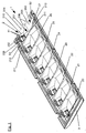
- eine perspektivische Ansicht eines Beleuchtungskörpers einer Leuchte, insbesondere einer Straßenleuchte, der gemäß einem bevorzugten Ausführungsbeispiel der vorliegenden Erfindung ausgeführt ist,
- Fig. 2
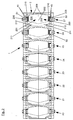
- eine Draufsicht auf einen Reflektor des Beleuchtungskörpers gemäß
Fig. 1 , - Fig. 3
- eine Seitenansicht des Reflektors gemäß
Fig. 2 , - Fig. 4
- einen Schnitt entlang einer Linie A-A gemäß
Fig. 3 , - Fig. 5
- eine Simulation der Strahlengänge einer Vielzahl von Primärstrahlen, die an einem Facettenreflektormittel eines Reflektorsegments reflektiert werden,
- Fig. 6
- eine Simulation der Strahlengänge einer Vielzahl von Primärstrahlen, die in dem Reflektorsegment des Beleuchtungskörpers Mehrfachreflexionen erfahren,
- Fig. 7
- eine Simulation der Strahlengänge einer Vielzahl von Primärstrahlen, die im Bereich einer gemeinsamen Stoßkante zweier Reflektorsegmente reflektiert werden.
- Fig. 1
- a perspective view of a lighting fixture of a lamp, in particular a street lamp, which is designed according to a preferred embodiment of the present invention,
- Fig. 2
- a plan view of a reflector of the lighting fixture according to
Fig. 1 . - Fig. 3
- a side view of the reflector according to
Fig. 2 . - Fig. 4
- a section along a line AA according to
Fig. 3 . - Fig. 5
- a simulation of the beam paths of a plurality of primary beams, which are reflected at a facet reflector means of a reflector segment,
- Fig. 6
- a simulation of the beam paths of a plurality of primary beams, which experience multiple reflections in the reflector segment of the lighting fixture,
- Fig. 7
- a simulation of the beam paths of a plurality of primary beams, which are reflected in the region of a common abutment edge of two reflector segments.
Unter Bezugnahme auf
Der Beleuchtungskörper 1 weist einen Reflektor 2 auf, der bei der Montage in ein erstes Gehäuseteil 3 eines Gehäuses einer Leuchte, insbesondere einer Straßenleuchte, eingesetzt werden kann und mit Hilfe geeigneter Befestigungsmittel an dem ersten Gehäuseteil 3 befestigt werden kann. Das Gehäuse der Leuchte weist überdies ein transparentes zweites Gehäuseteil auf, das an dem ersten Gehäuseteil 3 angebracht ist, jedoch hier aus Vereinfachungsgründen nicht explizit dargestellt ist. Der Reflektor 2 weist eine Mehrzahl von Reflektoreinheiten 20-27 auf, die in einer ersten Richtung, welche der Längsrichtung des Beleuchtungskörpers 1 entspricht, nebeneinander angeordnet sind.The
Jede der - in diesem Ausführungsbeispiel insgesamt acht - Reflektoreinheiten 20-27 ist zweiteilig ausgebildet und weist ein erstes Reflektorsegment 200 und ein, zum ersten Reflektorsegment 200 spiegelsymmetrisches zweites Reflektorsegment 201 auf, die einstückig und mehrfach gekantet ausgebildet sind und im Wesentlichen schaufelartig geformt sind. Auf diese schaufelartige Form der Reflektorsegmente 200, 201 wird weiter unten noch näher eingegangen. Die Reflektorsegmente 200, 201 sind mit Hilfe geeigneter Befestigungsmittel miteinander verbunden. Die Reflektorsegmente 200, 201 sind vorzugsweise aus Aluminium, insbesondere durch Blechbiegen, hergestellt. Es besteht alternativ auch die Möglichkeit, dass zwei einander gegenüberliegende Reflektorsegmente 200, 201 eine einstückige Einheit bilden.Each of the - in this embodiment a total of eight - reflector units 20-27 is formed in two parts and has a
Wie insbesondere in
Ausgehend von der Stoßkante 202, an der sich die beiden Reflektorsegmente 200, 201 treffen und aneinander stoßen, weist jedes der Reflektorsegmente 200, 201 eine schräg verlaufende ebene Reflexionsbasisfläche 203, 204 auf, die in einen in entgegengesetzter Richtung schräg verlaufenden und damit gegenüber der zugeordneten Reflexionsbasisfläche 203, 204 abgewinkelten Haltebereich 205, 206 münden. Ausgehend von der Stoßkante 202 verjüngen sich die ebenen Reflexionsbasisflächen 203, 204 in Richtung der entsprechenden Haltebereiche 205, 206. Jeder Haltebereich 205, 206 weist eine nicht mit Bezugszeichen versehene Ausnehmung auf, in der in diesem Ausführungsbeispiel jeweils zwei Multi-Chip-on-Board-LED-Leuchtmittel 40, 41 übereinander angeordnet sind. Grundsätzlich besteht auch die Möglichkeit, jedes Reflektorsegment 200, 201 mit lediglich einem Multi-Chip-on-Board-LED-Leuchtmittel 40, 41 oder mit mehr als zwei Multi-Chip-on-Board-LED-Leuchtmitteln 40, 41 auszustatten. Die beiden Multi-Chip-on-Board-LED-Leuchtmittel 40, die innerhalb des ersten Reflektorsegments 200 angeordnet sind, bilden vorliegend eine erste Gruppe von Multi-Chip-on-Board-LED-Leuchtmitteln 40 und die beiden Multi-Chip-on-Board-LED-Leuchtmittel 41, die innerhalb des zweiten Reflektorsegments 201 angeordnet sind, bilden demzufolge eine zweite Gruppe von Multi-Chip-on-Board-LED-Leuchtmitteln 41. Die ebene Reflexionsbasisfläche 203, 204 und die Haltebereiche 205, 206 des entsprechenden Reflektorsegments 200, 201 schließen miteinander einen Winkel > 90°, vorzugsweise einen Winkel zwischen 110° und 120°, ein.Starting from the abutting
Dadurch, dass bei dem hier vorgestellten Beleuchtungskörper 1 Multi-Chip-On-Board-LED-Leuchtmittel (kurz: MCOB-LED- Leuchtmittel) als Leuchtmittel verwendet werden, kann ein besonders hoher Betriebswirkungsgrad erreicht werden. Die Multi-Chip-On-Board-LED-Leuchtmittel 40, 41 besitzen im Gegensatz zur Single-Chip-LED-Technologie mehrere Emitterchips, die sich eine gemeinsame Phosphorkonversionsschicht teilen. Da ein großer Teil der Hitzeentwicklung während der Konversion im Phosphor geschieht, lässt sich hier über eine vergrößerte Fläche die entstehende Wärme viel besser ableiten als bei bei der Single-Chip-LED-Technologie. Während bei einer Single-Chip-LED der Emitter zumeist eine Größe von ca. 1 mm2 - 2 mm2 aufweist, können die Multi-Chip-On-Board-LED-Leuchtmittel 40, 41 durchaus einen Quadratzentimeter an emittierender Phosphoroberfläche aufweisen. Die größeren Emissionsflächen erlauben zwar keine kleinen optischen Abbildungen und eignen sich daher nicht für Anwendungen, die eine sehr hohe Lichtfokussierung verlangen. Dies ist bei Straßenbeleuchtungen, in denen der hier vorgestellte Beleuchtungskörper 1 bevorzugt verwendet werden kann, auch nicht erforderlich. Im Gegensatz zur Single-Chip-Technologie bieten Multi-Chip-On-Board-LED-Leuchtmittel 40, 41 entscheidende Vorteile für den Einsatz in der Straßenbeleuchtung. Zu nennen sind in diesem Zusammenhang insbesondere folgende Vorteile, die mit der Single-Chip-Technologie nicht zu erreichen sind:
- eine geringere Leuchtdichte kann die für den Betrieb einer Straßenleuchte, in der der erfindungsgemäße Beleuchtungskörper 1 verwendet wird, notwendige Blendungsbegrenzung zusätzlich unterstützen (die geringere Leuchtdichte infolge der großen Phosphorfläche stellt eine intrinsische Blendungsbegrenzung zur Verfügung),
- es kann eine gleichmäßige (homogene) Lichtverteilung in der Umgebung erhalten werden,
- eine großflächige Wärmeableitung ist möglich, so dass die Lebensdauer der Multi-Chip-On-Board-LED-
Leuchtmittel - die Montage ist sehr einfach,
- eine interne Reihen- und Parallelschaltung vieler LED-Chips ist möglich, so dass bei einem Ausfall einzelner LED-Chips das Multi-Chip-On-Board-LED-
Leuchtmittel
- a lower luminance may additionally support the glare limitation necessary for the operation of a street lamp in which the
lighting fixture 1 according to the invention is used (the lower luminance due to the large phosphor surface provides an intrinsic glare limitation), - it is possible to obtain a uniform (homogeneous) light distribution in the environment,
- large-area heat dissipation is possible, so that the service life of the multi-chip on-
board LED lamps - The assembly is very simple,
- an internal series and parallel connection of many LED chips is possible, so that in case of failure of individual LED chips, the multi-chip on-
board LED bulbs
Eine wirksame Wärmeableitung der während des Betriebs der Multi-Chip-On-Board-LED-Leuchtmittel 40, 41 generierten Wärme kann vorteilhaft über die aus Aluminium hergestellten Reflektorsegmente 200, 201 erfolgen.An effective heat dissipation of the heat generated during the operation of the multi-chip on-
Seitlich ist jedes der Reflektorsegmente 200, 201 durch eine erste Reflektorseitenwand mit zwei Reflexionsflächen 209, 210 und eine gegenüberliegende zweite Reflektorseitenwand mit ebenfalls zwei Reflexionsflächen 211, 212 begrenzt. Die Reflexionsflächen 209, 210, 211, 212 der Reflektorseitenwände schließen mit der Reflexionsbasisfläche 203, 204 des betreffenden Leuchtsegments 200, 201 jeweils einen Winkel > 90° ein. Eine der Reflexionsflächen 210, 212 einer jede Reflektorseitenwand ist gegenüber der anderen Reflexionsfläche 209, 211 nach innen abgekantet und mündet in den Haltebereich 205, 206 des betreffenden Reflektorsegments 200, 201. Die Reflexionsbasisflächen 203, 204, die vorliegend jeweils aus zwei Reflexionsflächen 209, 210, 211, 212 bestehenden Reflektorseitenwände sowie die Haltebereiche 205, 206 definieren die eingangs bereits erwähnte Schaufelform der Reflektorsegmente 200, 201.Each of the
Die Reflexionsbasisflächen 203, 204 und Reflexionsflächen 209, 210, 211, 212 der Reflektorseitenwände der Reflektorsegmente 200, 201 sind in diesem Ausführungsbeispiel mattiert ausgeführt. Auf Grund eher diffus reflektierender Lichtanteile werden relativ weiche Übergänge in der Lichtverteilung des an den Reflexionsbasisflächen 203, 204 und Reflexionsflächen 209, 210, 211, 212 der Reflektorseitenwände reflektierten Lichts erreicht.The reflection base surfaces 203, 204 and reflection surfaces 209, 210, 211, 212 of the reflector side walls of the
Im Bereich eines äußeren Endes der Haltebereiche 205, 206 jedes Reflektorsegments 200, 201 ist jeweils ein Facettenreflektormittel 50, 51 angeordnet. Jedes der Facettenreflektormittel 50, 51 weist eine Mehrzahl übereinander angeordneter Reihen nebeneinander angeordneter, vorzugsweise prismenartig geformter Reflexionsfacetten 500, 510 mit ebenen Reflexionsoberflächen auf. Die ebenen Reflexionsoberflächen der Reflexionsfacetten 500, 510 sind hochreflektierend (hochglänzend) ausgeführt, um den Reflexionsgrad und die Leuchtreichweite des Beleuchtungskörpers 1 zu vergrößern. Die Facettenreflektormittel 50, 51 erstrecken sich somit abschnittsweise über die Lichtkegel des von den Multi-Chip-on-Board-LED-Leuchtmitteln 40, 41 emittierten Primärlichts 400 hinweg.In the region of an outer end of the holding
Die Reflexionsoberflächen der Facettenreflektormittel 50, 51 in jeder der Reihen sind plan ausgeführt und zueinander angewinkelt und dabei so ausgebildet und angeordnet, dass die Reflexionsfacetten 500, 510 zumindest einen Teil des von den Multi-Chip-on-Board-LED-Leuchtmitteln 40, 41 direkt emittierten Primärlichts 400 reflektieren können, so dass das Licht ohne weitere Reflexionen als indirektes Licht 400' aus dem Beleuchtungskörper 1 in die Umgebung heraustreten kann. Diese Situation ist in
Um eine möglichst breite Strahlverteilung in einem zu beleuchtenden Bereich zu erhalten, weisen benachbarte Reihen von Reflexionsfacetten 500, 510 - wie in
Der Anteil des von den Facettenreflektormitteln 50, 51 desjenigen Reflektorsegments 200, 201, innerhalb dessen die Multi-Chip-on-Board-LED-Leuchtmittel 40, 41 und das ihnen unmittelbar zugeordnete Facettenreflektormittel 50, 51 angeordnet sind, reflektierten Lichts 400' beträgt typischerweise 30% bis 40%, insbesondere etwa 35%, des von den Multi-Chip-on-Board-LED-Leuchtmittel 40, 41 emittierten Primärlichts 400. Der Anteil des direkt (also ohne Reflexionen) aus den Reflektorsegmenten 200, 201 austretenden Lichts beträgt typischerweise 50% bis 60%, insbesondere etwa 55%, des emittierten Primärlichts 400.The proportion of the light 400 'reflected by the facet reflector means 50, 51 of that
Unter Bezugnahme auf
Die Reflexionsbasisflächen 203, 204 und Reflexionsflächen 209, 210, 211, 212 der Reflektorseitenwände beider Reflektorsegmente 200, 201 sind vorliegend als planare Flächen (ebene Flächen) ausgebildet. Ebenso sind die Reflexionsfacetten 500, 510 der Facettenreflektormittel 50, 51 planar ausgeführt. Nach umfangreichen Versuchen mit unterschiedlich gestalteten Freiformflächen hat sich die Verwendung planarer reflektiver Flächen als ausgesprochen vorteilhaft für die Vermeidung von Blendungseffekten erwiesen. Demgegenüber sind parabolische oder konkave Flächen in der Regel immer mit einer Fokusbildung und im ungünstigsten Fall mit einer sehr starken Erhöhung der beobachtbaren Leuchtdichte des Beleuchtungskörpers 1 unter bestimmten Betrachtungswinkeln verbunden. Das Abbilden der großen "Wendelbilder" der Multi-Chip-on-Board-LED-Leuchtmittel 40, 41 mit divergenten oder planaren reflektierenden Flächen eliminiert diesen Effekt. Es hat es sich ferner gezeigt, dass konvex geformte reflektierende Flächen eine ausreichende Bündelung des Lichts für die insbesondere bei Straßenleuchten notwendigen Reichweiten verhindern.The reflection base surfaces 203, 204 and reflection surfaces 209, 210, 211, 212 of the reflector side walls of both
Claims (8)
- Light fixture (1) of a luminaire, in particular a streetlamp, comprising- at least one reflector unit (20-27) having a first reflector segment (200) which comprises a multiplicity of reflective areas, and having a second reflector segment (201) which comprises a multiplicity of reflective areas, the two reflector segments (200, 201) being formed and arranged in such a way that, at least in some sections, they adjoin one another directly along a common abutting edge (202),- at least one first LED lighting means or a first group of LED lighting means, which is/are arranged within the first reflector segment (200),- at least one second LED lighting means or a second group of LED lighting means, which is/are arranged within the second reflector segment (201),- a first facetted reflector means (50) having a number of rows arranged one above another of reflective facets (500) arranged beside one another, which is fitted to an end of the first reflector segment (200) that is opposite the abutting edge (202), and- a second facetted reflector means (51) having a number of rows arranged one above another of reflective facets (510) arranged beside one another, which is fitted to an end of the second reflector segment (201) that is opposite the abutting edge (202),the reflective facets (500, 510) of the facetted reflectors (50, 51) being formed and arranged in such a way that they are able to reflect part of the light emitted, during operation, from the first and second LED lighting means or the first group and second group of LED lighting means in such a way that these parts are deflected into different target areas which overlap only partly geometrically, and
the reflective facets (500, 510) being arranged at an angle to the LED lighting means or the group of LED lighting means of the respective reflector segment (200, 201), the angles of inclination of the reflective facets (500, 510) in the row in which the reflective facets (500, 510) are arranged beside one another being identical or at least virtually identical,
characterized in that the reflective facets (500, 510) of adjacent rows of each facetted reflector means (50, 51) have angles of inclination which increase from inside to outside. - Light fixture (1) according to Claim 1,
characterized in that the reflective facets (500, 510) of the facetted reflector means (50, 51) have a highly glossy surface. - Light fixture (1) according to either of Claims 1 and 2, characterized in that, in the area of the abutting edge (202), the first reflector segment (200) and the second reflector segment (201) enclose an angle α between 130° and 150°, in particular an angle α of about 140°, with each other.
- Light fixture (1) according to one of Claims 1 to 3, characterized in that the reflector segments (200, 201) of the reflector (2) are shaped substantially in the manner of a shovel.
- Light fixture (1) according to one of Claims 1 to 4, characterized in that all the reflective areas of the reflector segments (200, 201) are planar.
- Light fixture (1) according to one of Claims 1 to 5, characterized in that at least some, preferably all, of the reflective areas of the reflector segments (200, 201) are made matt.
- Light fixture (1) according to one of Claims 1 to 6, characterized in that the LED lighting means are formed as multi-chip-on-board LED lighting means (40, 41).
- Luminaire, in particular streetlamp, having a housing within which at least one light fixture (1) is accommodated, characterized in that the light fixture (1) is implemented in accordance with one of Claims 1 to 7.
Priority Applications (2)
| Application Number | Priority Date | Filing Date | Title |
|---|---|---|---|
| SI201430114A SI2808601T1 (en) | 2013-05-31 | 2014-05-30 | Light fixture of a luminaire, in particular a streetlamp, and luminaire with at least one light fixture |
| PL14170634T PL2808601T3 (en) | 2013-05-31 | 2014-05-30 | Light fixture of a luminaire, in particular a streetlamp, and luminaire with at least one light fixture |
Applications Claiming Priority (1)
| Application Number | Priority Date | Filing Date | Title |
|---|---|---|---|
| DE102013105612.1A DE102013105612B4 (en) | 2013-05-31 | 2013-05-31 | Lighting fixture of a lamp, in particular a street lamp, and luminaire with at least one lighting fixture |
Publications (3)
| Publication Number | Publication Date |
|---|---|
| EP2808601A2 EP2808601A2 (en) | 2014-12-03 |
| EP2808601A3 EP2808601A3 (en) | 2015-01-14 |
| EP2808601B1 true EP2808601B1 (en) | 2016-09-21 |
Family
ID=50828790
Family Applications (1)
| Application Number | Title | Priority Date | Filing Date |
|---|---|---|---|
| EP14170634.1A Not-in-force EP2808601B1 (en) | 2013-05-31 | 2014-05-30 | Light fixture of a luminaire, in particular a streetlamp, and luminaire with at least one light fixture |
Country Status (5)
| Country | Link |
|---|---|
| EP (1) | EP2808601B1 (en) |
| DE (1) | DE102013105612B4 (en) |
| ES (1) | ES2608385T3 (en) |
| PL (1) | PL2808601T3 (en) |
| SI (1) | SI2808601T1 (en) |
Families Citing this family (2)
| Publication number | Priority date | Publication date | Assignee | Title |
|---|---|---|---|---|
| WO2016166624A2 (en) * | 2015-04-14 | 2016-10-20 | Simes S.P.A. | Lighting module |
| DE102016002072A1 (en) * | 2016-02-23 | 2017-08-24 | Selux Aktiengesellschaft | Luminaire with the bulbs opposite reflectors, kit and reflector for this |
Family Cites Families (9)
| Publication number | Priority date | Publication date | Assignee | Title |
|---|---|---|---|---|
| WO2006043195A1 (en) * | 2004-10-18 | 2006-04-27 | Koninklijke Philips Electronics N.V. | High efficiency led light source arrangement |
| DE202009014103U1 (en) | 2008-10-17 | 2010-03-11 | BöSha Technische Produkte GmbH & Co. KG | Lighting unit for a street lamp |
| DE102009034126A1 (en) * | 2008-10-17 | 2010-04-22 | BöSha Technische Produkte GmbH & Co. KG | Lighting unit for light i.e. streetlight, has reflector arranged such that surface-like, homogeneous illumination of environment of lighting unit is received during operation of lighting unit |
| DE102009058309A1 (en) * | 2009-07-09 | 2011-01-13 | Siteco Beleuchtungstechnik Gmbh | LED lights use |
| US8197105B2 (en) * | 2009-08-13 | 2012-06-12 | Intematix Corporation | LED-based lamps |
| DE102009056385A1 (en) * | 2009-11-30 | 2011-06-01 | Osram Gesellschaft mit beschränkter Haftung | Luminaire and traffic route lighting device |
| DE102010007774A1 (en) * | 2010-02-12 | 2011-08-18 | Siteco Beleuchtungstechnik GmbH, 83301 | Three-zone reflector |
| DE102010014099A1 (en) * | 2010-04-07 | 2011-10-13 | Siteco Beleuchtungstechnik Gmbh | Luminaire with cover |
| DE102011017161A1 (en) * | 2011-04-15 | 2012-10-18 | Cooper Crouse-Hinds Gmbh | lamp |
-
2013
- 2013-05-31 DE DE102013105612.1A patent/DE102013105612B4/en active Active
-
2014
- 2014-05-30 SI SI201430114A patent/SI2808601T1/en unknown
- 2014-05-30 ES ES14170634.1T patent/ES2608385T3/en active Active
- 2014-05-30 PL PL14170634T patent/PL2808601T3/en unknown
- 2014-05-30 EP EP14170634.1A patent/EP2808601B1/en not_active Not-in-force
Also Published As
| Publication number | Publication date |
|---|---|
| SI2808601T1 (en) | 2017-04-26 |
| PL2808601T3 (en) | 2017-05-31 |
| EP2808601A3 (en) | 2015-01-14 |
| DE102013105612B4 (en) | 2016-12-15 |
| ES2608385T3 (en) | 2017-04-10 |
| DE102013105612A1 (en) | 2014-12-04 |
| EP2808601A2 (en) | 2014-12-03 |
Similar Documents
| Publication | Publication Date | Title |
|---|---|---|
| EP1154200B1 (en) | Light distributor for a lighting assembly, lighting assembly and use of a lighting assembly | |
| DE102011085275B4 (en) | Optical element | |
| EP2307792B1 (en) | Luminaire | |
| DE102012220455A1 (en) | LIGHTING DEVICE WITH SEMICONDUCTOR LIGHT SOURCE | |
| EP2360427B1 (en) | Three zone reflector | |
| EP3012521B1 (en) | Light for a motor vehicle | |
| EP2553317B1 (en) | Light having led modules | |
| DE202009014103U1 (en) | Lighting unit for a street lamp | |
| DE102012223857A1 (en) | Laser activated remote phosphorus lighting device e.g. light, for use as e.g. headlight, has return beam mirror arranged apart from main direction of secondary light and arranged such that primary light portion is guided on converter region | |
| DE102010030296A1 (en) | lamp | |
| EP3037719B1 (en) | Led lense body for generating a direct and indirect light portion | |
| DE102009044387B4 (en) | LED outdoor light | |
| EP2808601B1 (en) | Light fixture of a luminaire, in particular a streetlamp, and luminaire with at least one light fixture | |
| EP2895790B1 (en) | Louver luminaire having led light sources | |
| EP3073179B1 (en) | Led module with vaned reflector and luminaire with corresponding led module | |
| AT15345U1 (en) | Luminaire arrangement and luminaire | |
| DE602004005872T2 (en) | LIGHTING AND METHOD OF LIGHTING | |
| EP0638764B2 (en) | Indoor lamp for mainly direct lighting | |
| EP2796779B1 (en) | Light with optical system for emitting light over an elongated light emission opening | |
| DE202012101368U1 (en) | lamp | |
| DE102009058308B4 (en) | Reflector for luminaires with ellipsoidal facets | |
| DE202020101683U1 (en) | Luminaire with light source and associated optics | |
| DE102009034126A1 (en) | Lighting unit for light i.e. streetlight, has reflector arranged such that surface-like, homogeneous illumination of environment of lighting unit is received during operation of lighting unit | |
| DE202020100899U1 (en) | Elongated lamp | |
| DE10247980A1 (en) | Automobile lamp with different lamp functions provided via respective LED light sources and associated reflection surfaces of common reflector elements |
Legal Events
| Date | Code | Title | Description |
|---|---|---|---|
| PUAI | Public reference made under article 153(3) epc to a published international application that has entered the european phase |
Free format text: ORIGINAL CODE: 0009012 |
|
| 17P | Request for examination filed |
Effective date: 20140530 |
|
| AK | Designated contracting states |
Kind code of ref document: A2 Designated state(s): AL AT BE BG CH CY CZ DE DK EE ES FI FR GB GR HR HU IE IS IT LI LT LU LV MC MK MT NL NO PL PT RO RS SE SI SK SM TR |
|
| AX | Request for extension of the european patent |
Extension state: BA ME |
|
| PUAL | Search report despatched |
Free format text: ORIGINAL CODE: 0009013 |
|
| AK | Designated contracting states |
Kind code of ref document: A3 Designated state(s): AL AT BE BG CH CY CZ DE DK EE ES FI FR GB GR HR HU IE IS IT LI LT LU LV MC MK MT NL NO PL PT RO RS SE SI SK SM TR |
|
| AX | Request for extension of the european patent |
Extension state: BA ME |
|
| RIC1 | Information provided on ipc code assigned before grant |
Ipc: F21V 7/09 20060101ALI20141211BHEP Ipc: F21V 7/04 20060101AFI20141211BHEP Ipc: F21Y 101/02 20060101ALN20141211BHEP Ipc: F21V 7/00 20060101ALI20141211BHEP Ipc: F21W 131/103 20060101ALN20141211BHEP |
|
| R17P | Request for examination filed (corrected) |
Effective date: 20150713 |
|
| RBV | Designated contracting states (corrected) |
Designated state(s): AL AT BE BG CH CY CZ DE DK EE ES FI FR GB GR HR HU IE IS IT LI LT LU LV MC MK MT NL NO PL PT RO RS SE SI SK SM TR |
|
| GRAP | Despatch of communication of intention to grant a patent |
Free format text: ORIGINAL CODE: EPIDOSNIGR1 |
|
| RIC1 | Information provided on ipc code assigned before grant |
Ipc: F21W 131/103 20060101ALN20160229BHEP Ipc: F21V 7/09 20060101ALI20160229BHEP Ipc: F21V 7/04 20060101AFI20160229BHEP Ipc: F21V 7/00 20060101ALI20160229BHEP |
|
| GRAS | Grant fee paid |
Free format text: ORIGINAL CODE: EPIDOSNIGR3 |
|
| INTG | Intention to grant announced |
Effective date: 20160318 |
|
| GRAA | (expected) grant |
Free format text: ORIGINAL CODE: 0009210 |
|
| AK | Designated contracting states |
Kind code of ref document: B1 Designated state(s): AL AT BE BG CH CY CZ DE DK EE ES FI FR GB GR HR HU IE IS IT LI LT LU LV MC MK MT NL NO PL PT RO RS SE SI SK SM TR |
|
| REG | Reference to a national code |
Ref country code: GB Ref legal event code: FG4D Free format text: NOT ENGLISH |
|
| REG | Reference to a national code |
Ref country code: CH Ref legal event code: EP |
|
| REG | Reference to a national code |
Ref country code: AT Ref legal event code: REF Ref document number: 831351 Country of ref document: AT Kind code of ref document: T Effective date: 20161015 |
|
| REG | Reference to a national code |
Ref country code: IE Ref legal event code: FG4D Free format text: LANGUAGE OF EP DOCUMENT: GERMAN |
|
| REG | Reference to a national code |
Ref country code: DE Ref legal event code: R096 Ref document number: 502014001504 Country of ref document: DE |
|
| REG | Reference to a national code |
Ref country code: NL Ref legal event code: FP |
|
| REG | Reference to a national code |
Ref country code: LT Ref legal event code: MG4D |
|
| PG25 | Lapsed in a contracting state [announced via postgrant information from national office to epo] |
Ref country code: FI Free format text: LAPSE BECAUSE OF FAILURE TO SUBMIT A TRANSLATION OF THE DESCRIPTION OR TO PAY THE FEE WITHIN THE PRESCRIBED TIME-LIMIT Effective date: 20160921 Ref country code: NO Free format text: LAPSE BECAUSE OF FAILURE TO SUBMIT A TRANSLATION OF THE DESCRIPTION OR TO PAY THE FEE WITHIN THE PRESCRIBED TIME-LIMIT Effective date: 20161221 Ref country code: RS Free format text: LAPSE BECAUSE OF FAILURE TO SUBMIT A TRANSLATION OF THE DESCRIPTION OR TO PAY THE FEE WITHIN THE PRESCRIBED TIME-LIMIT Effective date: 20160921 Ref country code: LT Free format text: LAPSE BECAUSE OF FAILURE TO SUBMIT A TRANSLATION OF THE DESCRIPTION OR TO PAY THE FEE WITHIN THE PRESCRIBED TIME-LIMIT Effective date: 20160921 |
|
| PG25 | Lapsed in a contracting state [announced via postgrant information from national office to epo] |
Ref country code: LV Free format text: LAPSE BECAUSE OF FAILURE TO SUBMIT A TRANSLATION OF THE DESCRIPTION OR TO PAY THE FEE WITHIN THE PRESCRIBED TIME-LIMIT Effective date: 20160921 Ref country code: GR Free format text: LAPSE BECAUSE OF FAILURE TO SUBMIT A TRANSLATION OF THE DESCRIPTION OR TO PAY THE FEE WITHIN THE PRESCRIBED TIME-LIMIT Effective date: 20161222 Ref country code: SE Free format text: LAPSE BECAUSE OF FAILURE TO SUBMIT A TRANSLATION OF THE DESCRIPTION OR TO PAY THE FEE WITHIN THE PRESCRIBED TIME-LIMIT Effective date: 20160921 |
|
| REG | Reference to a national code |
Ref country code: ES Ref legal event code: FG2A Ref document number: 2608385 Country of ref document: ES Kind code of ref document: T3 Effective date: 20170410 |
|
| PG25 | Lapsed in a contracting state [announced via postgrant information from national office to epo] |
Ref country code: RO Free format text: LAPSE BECAUSE OF FAILURE TO SUBMIT A TRANSLATION OF THE DESCRIPTION OR TO PAY THE FEE WITHIN THE PRESCRIBED TIME-LIMIT Effective date: 20160921 Ref country code: EE Free format text: LAPSE BECAUSE OF FAILURE TO SUBMIT A TRANSLATION OF THE DESCRIPTION OR TO PAY THE FEE WITHIN THE PRESCRIBED TIME-LIMIT Effective date: 20160921 |
|
| REG | Reference to a national code |
Ref country code: DE Ref legal event code: R082 Ref document number: 502014001504 Country of ref document: DE Representative=s name: PATENT- UND RECHTSANWAELTE LOESENBECK, SPECHT,, DE Ref country code: FR Ref legal event code: PLFP Year of fee payment: 4 |
|
| PG25 | Lapsed in a contracting state [announced via postgrant information from national office to epo] |
Ref country code: PT Free format text: LAPSE BECAUSE OF FAILURE TO SUBMIT A TRANSLATION OF THE DESCRIPTION OR TO PAY THE FEE WITHIN THE PRESCRIBED TIME-LIMIT Effective date: 20170123 Ref country code: SM Free format text: LAPSE BECAUSE OF FAILURE TO SUBMIT A TRANSLATION OF THE DESCRIPTION OR TO PAY THE FEE WITHIN THE PRESCRIBED TIME-LIMIT Effective date: 20160921 Ref country code: BG Free format text: LAPSE BECAUSE OF FAILURE TO SUBMIT A TRANSLATION OF THE DESCRIPTION OR TO PAY THE FEE WITHIN THE PRESCRIBED TIME-LIMIT Effective date: 20161221 Ref country code: SK Free format text: LAPSE BECAUSE OF FAILURE TO SUBMIT A TRANSLATION OF THE DESCRIPTION OR TO PAY THE FEE WITHIN THE PRESCRIBED TIME-LIMIT Effective date: 20160921 Ref country code: CZ Free format text: LAPSE BECAUSE OF FAILURE TO SUBMIT A TRANSLATION OF THE DESCRIPTION OR TO PAY THE FEE WITHIN THE PRESCRIBED TIME-LIMIT Effective date: 20160921 Ref country code: IS Free format text: LAPSE BECAUSE OF FAILURE TO SUBMIT A TRANSLATION OF THE DESCRIPTION OR TO PAY THE FEE WITHIN THE PRESCRIBED TIME-LIMIT Effective date: 20170121 |
|
| REG | Reference to a national code |
Ref country code: DE Ref legal event code: R097 Ref document number: 502014001504 Country of ref document: DE |
|
| PLBE | No opposition filed within time limit |
Free format text: ORIGINAL CODE: 0009261 |
|
| STAA | Information on the status of an ep patent application or granted ep patent |
Free format text: STATUS: NO OPPOSITION FILED WITHIN TIME LIMIT |
|
| PG25 | Lapsed in a contracting state [announced via postgrant information from national office to epo] |
Ref country code: DK Free format text: LAPSE BECAUSE OF FAILURE TO SUBMIT A TRANSLATION OF THE DESCRIPTION OR TO PAY THE FEE WITHIN THE PRESCRIBED TIME-LIMIT Effective date: 20160921 |
|
| 26N | No opposition filed |
Effective date: 20170622 |
|
| PG25 | Lapsed in a contracting state [announced via postgrant information from national office to epo] |
Ref country code: LU Free format text: LAPSE BECAUSE OF NON-PAYMENT OF DUE FEES Effective date: 20170531 |
|
| REG | Reference to a national code |
Ref country code: CH Ref legal event code: PL |
|
| PG25 | Lapsed in a contracting state [announced via postgrant information from national office to epo] |
Ref country code: MC Free format text: LAPSE BECAUSE OF FAILURE TO SUBMIT A TRANSLATION OF THE DESCRIPTION OR TO PAY THE FEE WITHIN THE PRESCRIBED TIME-LIMIT Effective date: 20160921 |
|
| REG | Reference to a national code |
Ref country code: IE Ref legal event code: MM4A |
|
| PG25 | Lapsed in a contracting state [announced via postgrant information from national office to epo] |
Ref country code: LI Free format text: LAPSE BECAUSE OF NON-PAYMENT OF DUE FEES Effective date: 20170531 Ref country code: CH Free format text: LAPSE BECAUSE OF NON-PAYMENT OF DUE FEES Effective date: 20170531 |
|
| PG25 | Lapsed in a contracting state [announced via postgrant information from national office to epo] |
Ref country code: LU Free format text: LAPSE BECAUSE OF NON-PAYMENT OF DUE FEES Effective date: 20170530 |
|
| REG | Reference to a national code |
Ref country code: BE Ref legal event code: MM Effective date: 20170531 |
|
| PG25 | Lapsed in a contracting state [announced via postgrant information from national office to epo] |
Ref country code: IE Free format text: LAPSE BECAUSE OF NON-PAYMENT OF DUE FEES Effective date: 20170530 |
|
| REG | Reference to a national code |
Ref country code: FR Ref legal event code: PLFP Year of fee payment: 5 |
|
| PG25 | Lapsed in a contracting state [announced via postgrant information from national office to epo] |
Ref country code: BE Free format text: LAPSE BECAUSE OF NON-PAYMENT OF DUE FEES Effective date: 20170531 |
|
| PG25 | Lapsed in a contracting state [announced via postgrant information from national office to epo] |
Ref country code: MT Free format text: LAPSE BECAUSE OF FAILURE TO SUBMIT A TRANSLATION OF THE DESCRIPTION OR TO PAY THE FEE WITHIN THE PRESCRIBED TIME-LIMIT Effective date: 20160921 |
|
| PG25 | Lapsed in a contracting state [announced via postgrant information from national office to epo] |
Ref country code: AL Free format text: LAPSE BECAUSE OF FAILURE TO SUBMIT A TRANSLATION OF THE DESCRIPTION OR TO PAY THE FEE WITHIN THE PRESCRIBED TIME-LIMIT Effective date: 20160921 |
|
| GBPC | Gb: european patent ceased through non-payment of renewal fee |
Effective date: 20180530 |
|
| PG25 | Lapsed in a contracting state [announced via postgrant information from national office to epo] |
Ref country code: GB Free format text: LAPSE BECAUSE OF NON-PAYMENT OF DUE FEES Effective date: 20180530 |
|
| PG25 | Lapsed in a contracting state [announced via postgrant information from national office to epo] |
Ref country code: HU Free format text: LAPSE BECAUSE OF FAILURE TO SUBMIT A TRANSLATION OF THE DESCRIPTION OR TO PAY THE FEE WITHIN THE PRESCRIBED TIME-LIMIT; INVALID AB INITIO Effective date: 20140530 |
|
| PG25 | Lapsed in a contracting state [announced via postgrant information from national office to epo] |
Ref country code: CY Free format text: LAPSE BECAUSE OF FAILURE TO SUBMIT A TRANSLATION OF THE DESCRIPTION OR TO PAY THE FEE WITHIN THE PRESCRIBED TIME-LIMIT Effective date: 20160921 |
|
| PG25 | Lapsed in a contracting state [announced via postgrant information from national office to epo] |
Ref country code: MK Free format text: LAPSE BECAUSE OF FAILURE TO SUBMIT A TRANSLATION OF THE DESCRIPTION OR TO PAY THE FEE WITHIN THE PRESCRIBED TIME-LIMIT Effective date: 20160921 |
|
| PG25 | Lapsed in a contracting state [announced via postgrant information from national office to epo] |
Ref country code: TR Free format text: LAPSE BECAUSE OF FAILURE TO SUBMIT A TRANSLATION OF THE DESCRIPTION OR TO PAY THE FEE WITHIN THE PRESCRIBED TIME-LIMIT Effective date: 20160921 |
|
| PG25 | Lapsed in a contracting state [announced via postgrant information from national office to epo] |
Ref country code: HR Free format text: LAPSE BECAUSE OF FAILURE TO SUBMIT A TRANSLATION OF THE DESCRIPTION OR TO PAY THE FEE WITHIN THE PRESCRIBED TIME-LIMIT Effective date: 20160921 |
|
| PGFP | Annual fee paid to national office [announced via postgrant information from national office to epo] |
Ref country code: PL Payment date: 20210304 Year of fee payment: 8 |
|
| PGFP | Annual fee paid to national office [announced via postgrant information from national office to epo] |
Ref country code: IT Payment date: 20210531 Year of fee payment: 8 Ref country code: FR Payment date: 20210422 Year of fee payment: 8 Ref country code: DE Payment date: 20210531 Year of fee payment: 8 |
|
| PGFP | Annual fee paid to national office [announced via postgrant information from national office to epo] |
Ref country code: SI Payment date: 20210519 Year of fee payment: 8 Ref country code: AT Payment date: 20210426 Year of fee payment: 8 Ref country code: ES Payment date: 20210614 Year of fee payment: 8 |
|
| PGFP | Annual fee paid to national office [announced via postgrant information from national office to epo] |
Ref country code: NL Payment date: 20210412 Year of fee payment: 8 |
|
| REG | Reference to a national code |
Ref country code: DE Ref legal event code: R119 Ref document number: 502014001504 Country of ref document: DE |
|
| REG | Reference to a national code |
Ref country code: NL Ref legal event code: MM Effective date: 20220601 |
|
| REG | Reference to a national code |
Ref country code: AT Ref legal event code: MM01 Ref document number: 831351 Country of ref document: AT Kind code of ref document: T Effective date: 20220530 |
|
| PG25 | Lapsed in a contracting state [announced via postgrant information from national office to epo] |
Ref country code: AT Free format text: LAPSE BECAUSE OF NON-PAYMENT OF DUE FEES Effective date: 20220530 |
|
| PG25 | Lapsed in a contracting state [announced via postgrant information from national office to epo] |
Ref country code: SI Free format text: LAPSE BECAUSE OF NON-PAYMENT OF DUE FEES Effective date: 20220531 |
|
| PG25 | Lapsed in a contracting state [announced via postgrant information from national office to epo] |
Ref country code: FR Free format text: LAPSE BECAUSE OF NON-PAYMENT OF DUE FEES Effective date: 20220531 |
|
| PG25 | Lapsed in a contracting state [announced via postgrant information from national office to epo] |
Ref country code: DE Free format text: LAPSE BECAUSE OF NON-PAYMENT OF DUE FEES Effective date: 20221201 |
|
| PG25 | Lapsed in a contracting state [announced via postgrant information from national office to epo] |
Ref country code: NL Free format text: LAPSE BECAUSE OF NON-PAYMENT OF DUE FEES Effective date: 20220601 |
|
| REG | Reference to a national code |
Ref country code: ES Ref legal event code: FD2A Effective date: 20230728 |
|
| PG25 | Lapsed in a contracting state [announced via postgrant information from national office to epo] |
Ref country code: IT Free format text: LAPSE BECAUSE OF NON-PAYMENT OF DUE FEES Effective date: 20220530 |
|
| PG25 | Lapsed in a contracting state [announced via postgrant information from national office to epo] |
Ref country code: PL Free format text: LAPSE BECAUSE OF NON-PAYMENT OF DUE FEES Effective date: 20220530 |
|
| PG25 | Lapsed in a contracting state [announced via postgrant information from national office to epo] |
Ref country code: ES Free format text: LAPSE BECAUSE OF NON-PAYMENT OF DUE FEES Effective date: 20220531 |