EP2808558B1 - Strukturbaugruppe für eine Strömungsmaschine - Google Patents
Strukturbaugruppe für eine Strömungsmaschine Download PDFInfo
- Publication number
- EP2808558B1 EP2808558B1 EP14170065.8A EP14170065A EP2808558B1 EP 2808558 B1 EP2808558 B1 EP 2808558B1 EP 14170065 A EP14170065 A EP 14170065A EP 2808558 B1 EP2808558 B1 EP 2808558B1
- Authority
- EP
- European Patent Office
- Prior art keywords
- flow path
- main flow
- assembly
- component
- accordance
- Prior art date
- Legal status (The legal status is an assumption and is not a legal conclusion. Google has not performed a legal analysis and makes no representation as to the accuracy of the status listed.)
- Not-in-force
Links
- 230000037431 insertion Effects 0.000 claims 5
- 238000003780 insertion Methods 0.000 claims 5
- 239000012530 fluid Substances 0.000 description 22
- 239000000243 solution Substances 0.000 description 7
- 238000011282 treatment Methods 0.000 description 7
- 238000004519 manufacturing process Methods 0.000 description 4
- 230000000712 assembly Effects 0.000 description 2
- 238000000429 assembly Methods 0.000 description 2
- 230000015572 biosynthetic process Effects 0.000 description 2
- 238000002347 injection Methods 0.000 description 2
- 239000007924 injection Substances 0.000 description 2
- 230000000149 penetrating effect Effects 0.000 description 2
- 238000011144 upstream manufacturing Methods 0.000 description 2
- 238000005266 casting Methods 0.000 description 1
- 230000000295 complement effect Effects 0.000 description 1
- 230000002401 inhibitory effect Effects 0.000 description 1
- 239000007788 liquid Substances 0.000 description 1
- 238000003754 machining Methods 0.000 description 1
- 230000004048 modification Effects 0.000 description 1
- 238000012986 modification Methods 0.000 description 1
- 238000000926 separation method Methods 0.000 description 1
- 238000007493 shaping process Methods 0.000 description 1
- 238000005245 sintering Methods 0.000 description 1
- 229910000679 solder Inorganic materials 0.000 description 1
Images


Classifications
-
- F—MECHANICAL ENGINEERING; LIGHTING; HEATING; WEAPONS; BLASTING
- F01—MACHINES OR ENGINES IN GENERAL; ENGINE PLANTS IN GENERAL; STEAM ENGINES
- F01D—NON-POSITIVE DISPLACEMENT MACHINES OR ENGINES, e.g. STEAM TURBINES
- F01D17/00—Regulating or controlling by varying flow
- F01D17/10—Final actuators
- F01D17/105—Final actuators by passing part of the fluid
-
- F—MECHANICAL ENGINEERING; LIGHTING; HEATING; WEAPONS; BLASTING
- F04—POSITIVE - DISPLACEMENT MACHINES FOR LIQUIDS; PUMPS FOR LIQUIDS OR ELASTIC FLUIDS
- F04D—NON-POSITIVE-DISPLACEMENT PUMPS
- F04D29/00—Details, component parts, or accessories
- F04D29/40—Casings; Connections of working fluid
- F04D29/52—Casings; Connections of working fluid for axial pumps
- F04D29/522—Casings; Connections of working fluid for axial pumps especially adapted for elastic fluid pumps
- F04D29/526—Details of the casing section radially opposing blade tips
-
- F—MECHANICAL ENGINEERING; LIGHTING; HEATING; WEAPONS; BLASTING
- F04—POSITIVE - DISPLACEMENT MACHINES FOR LIQUIDS; PUMPS FOR LIQUIDS OR ELASTIC FLUIDS
- F04D—NON-POSITIVE-DISPLACEMENT PUMPS
- F04D29/00—Details, component parts, or accessories
- F04D29/40—Casings; Connections of working fluid
- F04D29/52—Casings; Connections of working fluid for axial pumps
- F04D29/54—Fluid-guiding means, e.g. diffusers
- F04D29/541—Specially adapted for elastic fluid pumps
-
- F—MECHANICAL ENGINEERING; LIGHTING; HEATING; WEAPONS; BLASTING
- F04—POSITIVE - DISPLACEMENT MACHINES FOR LIQUIDS; PUMPS FOR LIQUIDS OR ELASTIC FLUIDS
- F04D—NON-POSITIVE-DISPLACEMENT PUMPS
- F04D29/00—Details, component parts, or accessories
- F04D29/66—Combating cavitation, whirls, noise, vibration or the like; Balancing
- F04D29/68—Combating cavitation, whirls, noise, vibration or the like; Balancing by influencing boundary layers
- F04D29/681—Combating cavitation, whirls, noise, vibration or the like; Balancing by influencing boundary layers especially adapted for elastic fluid pumps
- F04D29/685—Inducing localised fluid recirculation in the stator-rotor interface
-
- F—MECHANICAL ENGINEERING; LIGHTING; HEATING; WEAPONS; BLASTING
- F05—INDEXING SCHEMES RELATING TO ENGINES OR PUMPS IN VARIOUS SUBCLASSES OF CLASSES F01-F04
- F05D—INDEXING SCHEME FOR ASPECTS RELATING TO NON-POSITIVE-DISPLACEMENT MACHINES OR ENGINES, GAS-TURBINES OR JET-PROPULSION PLANTS
- F05D2260/00—Function
- F05D2260/15—Load balancing
-
- F—MECHANICAL ENGINEERING; LIGHTING; HEATING; WEAPONS; BLASTING
- F05—INDEXING SCHEMES RELATING TO ENGINES OR PUMPS IN VARIOUS SUBCLASSES OF CLASSES F01-F04
- F05D—INDEXING SCHEME FOR ASPECTS RELATING TO NON-POSITIVE-DISPLACEMENT MACHINES OR ENGINES, GAS-TURBINES OR JET-PROPULSION PLANTS
- F05D2260/00—Function
- F05D2260/60—Fluid transfer
- F05D2260/606—Bypassing the fluid
-
- F—MECHANICAL ENGINEERING; LIGHTING; HEATING; WEAPONS; BLASTING
- F05—INDEXING SCHEMES RELATING TO ENGINES OR PUMPS IN VARIOUS SUBCLASSES OF CLASSES F01-F04
- F05D—INDEXING SCHEME FOR ASPECTS RELATING TO NON-POSITIVE-DISPLACEMENT MACHINES OR ENGINES, GAS-TURBINES OR JET-PROPULSION PLANTS
- F05D2270/00—Control
- F05D2270/01—Purpose of the control system
- F05D2270/17—Purpose of the control system to control boundary layer
Definitions
- the invention relates to a structural assembly for a turbomachine according to the preamble of patent claim 1.
- turbomachines in particular of fluid flow machines such as fans, compressors, pumps and fans, is limited by the growth and separation of boundary layers in the rotor and stator tip areas near the housing or hub wall. In the case of blade rows with a running gap, this leads to high secondary losses and possibly to the occurrence of operational instabilities at higher loads.
- casing treatments As a countermeasure, it is known to use so-called casing treatments.
- the simplest form of casing treatments are circumferential grooves with a rectangular or parallelogram-shaped cross-section, as used, for example, in US Pat EP 0 754 864 A1 are disclosed.
- Other solutions provide for rows of slots or openings in the housing, the individual slots / openings being oriented substantially in the flow direction and having a slender shape with a small extension viewed in the circumferential direction of the machine. Such solutions are for example in the DE 101 35 003 C1 disclosed.
- a fluid flow machine which forms at least one secondary flow channel in the area of the blade leading edge in a main flow path boundary, which connects two openings arranged on the main flow path boundary.
- Each secondary flow channel in each case connects a removal opening with a supply opening provided further upstream.
- the US 2012/0201654 A1 describes a structural assembly for a turbomachine according to the preamble of claim 1.
- an inner housing part In the inner housing part is a recess provided, in which an air supply element can be used.
- the air supply element is firmly installed between the two housing parts.
- the structural assembly has at least one support member and at least one directly or indirectly connected to the support member, replaceable plug.
- the neck is directly connected to the support member, e.g. arranged on the circumference of the support member, or the connecting piece is connected to a component connected to the support member and thus indirectly to the support member.
- the replaceable plug comprises a subsection of a secondary flow channel, the subsection completing at least one further subsection of the secondary flow channel extending outside of the plug in the structural assembly to a secondary flow passage continuous between its openings.
- the solution according to the invention has the advantage that the secondary flow channel can be interrupted or varied by replacing the plug. Also, in the event of wear, a portion of the secondary flow channel formed in the plug can be replaced in a simple manner. In the plug simultaneously spatially compact and robust three-dimensional structures of a secondary flow channel can be provided.
- the invention thus contemplates a portion of the main flowpath of a turbomachine, in the region of a free end and a nip row of blades, in which a series of circumferentially distributed secondary flow channels are provided.
- the course of the secondary flow channels can each be spatially complex.
- a structural assembly is provided for structurally implementing said secondary flow channels.
- the replaceable plug penetrates at least one structural component which overhangs the main flow path and which is the support component or a further component.
- the support component forms at least part of the main flow path boundary with at least part of its surfaces.
- the replaceable plug extends in a substantially radial direction relative to the main flow path and forms an end face which forms part of the main flow path boundary. According to one embodiment, at least one of the openings of the secondary flow channel is formed in the end face of the replaceable plug.
- At least one subsection of a secondary flow channel is realized in the support component, so that at least the support component and the plug accommodate subsections of the secondary flow channel. Further sections can be provided by further components.
- the support member is formed as an annular housing or as a half-shell housing a turbomachine, or the support member is formed like a ring or half-ring on the hub of a turbomachine.
- the support member according to the invention is structurally such that for the purpose of assembly and disassembly of the replaceable plug from the main flow path side facing a direct access to the interchangeable plug is given, so that the replaceable plug from the main flow path side facing away from the support member without disassembly of other structural components is replaceable ,
- the structural assembly according to the invention further comprises at least one insert member, wherein in the support member is provided a circumferentially extending recess which receives along the circumference at least one insert member, and wherein each insert member forms part of the surfaces of a part of the Hauptströmungspfaderbandung and at least forms a portion of a secondary flow channel.
- the insert member is completely penetrated at the periphery of at least one replaceable plug, such that the end face of the replaceable plug forms part of the Hauptströmungspfadberandung. It can also be provided that the replaceable plug penetrates only the insert component and there has a defined seat, wherein the support member is a local
- the structural assembly according to the invention further comprises at least one connecting member, wherein the connecting member substantially on the side facing away from the main flow path side of the support member to the support member, and wherein the connecting member forms at least a portion of a secondary flow channel.
- the support member is completely penetrated at the periphery of at least one replaceable plug such that the end face of the replaceable plug forms part of the main flow path boundary, wherein portions of a secondary flow channel are formed in the support member, in the connection member and in the replaceable plug and complement each other to a continuous secondary flow channel.
- a further variant of the invention provides that the connecting component is installed in recesses in the support component in the area of at least one end of the secondary flow channel and in this way directly adjoins the main flow path.
- the connecting component thus also forms an opening-near region of the secondary flow channel.
- At least one connecting piece can be formed on the side of the support component facing away from the main flow path on the circumference of the support component. Also, on the side facing away from the main flow path side of the support member is at least one, at least along a portion of the circumference continuously extending web for receiving at least one interchangeable plug is formed.
- the replaceable plug is designed as a multi-part element.
- an embodiment variant provides that the replaceable plug is subdivided into partial plugs along at least partial sections of the secondary flow channel.
- a further embodiment provides that the replaceable plug is formed in two parts and provided a fixing top plug and a example with a defined seat Understop comprises, with upper and lower plugs together form the interchangeable plug.
- the fixation of the interchangeable plug is realized by a fit, a press fit, a plug, a clamp or a screw.
- the interchangeable plug with implemented portion of a secondary flow channel may be replaced by a blind plug with no channel implemented for the purpose of inhibiting flow through the secondary flow channel.
- the present invention relates generally to structural assemblies for turbomachines, such as turbines, and to particular fluid flow machines, such as fans, compressors, pumps, and fans, in both axial, semi-axial, and radial designs.
- the working medium or fluid may be gaseous or liquid.
- the turbomachine may include one or more stages each having a rotor and a stator. In some cases, the stage is formed only by a rotor.
- the rotor of a turbomachine in which a structural assembly according to the invention is used, consists of a number of blades, which are connected to the rotating shaft of the turbomachine and deliver energy to the working fluid in the case of the fluid flow machine.
- the rotor can be designed with or without shroud on the outer blade end.
- the stator of a turbomachine in which a structural assembly according to the invention is used, consists of a number of stationary blades, which can be designed on the hub side as the housing side with a fixed or free blade end.
- the rotor drum and the blading are usually surrounded by a housing. In other cases, z. As in propellers or propellers, no housing exists.
- a turbomachine in which a structural assembly according to the invention is used, can also have a stator in front of the first rotor, a so-called leading wheel. At least one stator or Vorleitrad - may be rotatably mounted - deviating from an immovable fixation - to change the angle of attack can. A Adjustment takes place for example by a spindle accessible from outside the annular channel.
- a turbomachine in which a structural assembly according to the invention is used, have at least one row of adjustable rotors.
- a turbomachine in which a structural assembly according to the invention is used in multi-stage have two opposing waves, so that the rotor blade rows change the direction of rotation from stage to stage. There are no stators between successive rotors.
- a turbomachine in which a structural assembly according to the invention is used have a bypass configuration such that a single-flow annular channel behind a certain row of blades divides into two concentric annular channels, which in turn accommodate at least one more row of blades.
- turbomachine in which a structural assembly according to the invention is used, it is, for example, a jet engine, in particular a turbofan engine.
- the structural assembly is formed, for example, in the region of a compressor of a jet engine or turbofan engine.
- the invention further relates to a fluid flow machine with a structural assembly according to the invention.
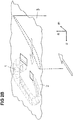
- the Fig. 2A shows an arrangement of a blade row 3 with free end and running gap 5 in the meridian plane formed by the axial direction x and the radial direction r.
- the nip 5 separates the blade tip from a component 2 belonging to the main flow path at the hub or housing of the fluid flow machine.
- the component 2 forms a main flow path boundary 4 toward the main flow path.
- the main flow direction in the main flow path is indicated by an arrow A. Upstream and / or downstream of the row of blades 3 with running gap, further rows of blades may be located.
- Within the main flow path belonging to the component 2 is in the region of the running gap 5 a number of the circumference distributed secondary flow channels 1 are provided, which each form an opening at their ends (feed opening and removal opening).
- Fig. 2A shows the outline or the projection of a single secondary flow channel 1 in the meridian plane (xr).
- xr meridian plane
- each channel 1 has a three-dimensional spatially twisted course, which in the Fig. 2B is shown by way of example.
- cross-sectional shape of the secondary flow channels 1 in the Fig. 2B merely exemplified as rectangular.
- the cross section of the secondary flow channels 1 may be formed in other embodiments without corners, in particular circular or elliptical.
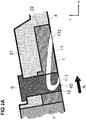
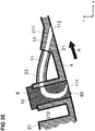
- FIG. 3A shows a structural assembly according to the invention in the region of a row of blades with running gap in the meridian view (xr).
- the main flow direction is indicated by an arrow A.
- the blade row is no longer shown in favor of a simpler representation.
- At least one secondary flow channel 1 is formed, which has two openings 111, 112 in the main flow path boundary 4 and is connected via this to the main flow path.
- the secondary flow channel 11 is designed as a single-path path with an opening through which fluid flows from the main flow channel into the secondary flow channel 1 and a second opening, through which the fluid leaves the secondary flow channel 1.
- At least one of the secondary flow channels is formed by an arrangement in which a single channel is divided along its course into at least two subchannels, thereby forming a kind of "trouser configuration".
- an inflow port and a plurality of outflow ports are included, which belong to the secondary flow passage.
- at least one of the secondary flow channels is formed by an arrangement in which at least two Channels are merged into a channel, in which case a plurality of inflow and a discharge port to the secondary flow passage.
- the secondary flow channel 1 is realized in a structural assembly comprising a support member 21, an insert member 22 and a replaceable plug 6.
- the support member 21 is formed as an annular housing of a turbomachine or as a half shell housing a turbomachine. With a corresponding arrangement in the hub region, it is, for example, annularly formed on the hub of a turbomachine or semi-annular on the hub of a turbomachine.
- a recess extending in the circumferential direction is provided, in which at least one insert member 22 is inserted along the circumference.
- the insert component 21 forms part of its surfaces with a part of the main flow path boundary 4.
- the replaceable plug 6 extends in a substantially radial direction with respect to the main flow path, penetrating both the support member 21 and the insert member 22.
- the plug 6 has an end face 60 which forms part of the main flow path boundary 4.
- the secondary flow channel 1 comprises two subsections 11, 12, wherein one subsection 11 is formed in the insert component 22 and the other subsection 12 is formed in the interchangeable plug 6.
- the one of the two openings 111, 112 of the secondary flow channel 1 is in the insert member 22 and the other of the openings 111, 112 of the secondary flow channel 1 is in Plug 6 is formed.
- the insert member 22 is inserted in the axial direction in the corresponding recess in the support member 21.
- a fixation of the components 21, 22 to each other in the axial direction can be effected by a further component 7.
- portion 12 of the secondary flow channel 1 is provided by means of internal surfaces of the plug 6, that is not by means of structures formed on the outside of the plug 6.
- a portion 12 of the secondary flow channel 1 in a replaceable plug 6 is associated with the advantage that it is possible by replacing the plug 6 by a blind plug without integrated channel section, to prevent the flow through the secondary flow channel 1.
- a flow through a secondary flow channel can be switched on and off.
- various plugs 6 in which the partial section 12 realized in the stopper 6 is embodied in different ways, in each case complementing the partial section 11 formed in the insert component 22. In this way, the formation of the secondary flow channel 1 and the flow occurring therein can be varied in a simple manner.
- FIG. 3B shows a further embodiment of a structural assembly in the region of a row of blades with running gap in the meridian view (xr).
- the embodiment of FIG. 3B differs from the embodiment of FIG. 3A in that the replaceable plug 6 is designed as a multipart element.
- the plug 6 is divided into two sub-plugs 61, 62, wherein in principle more than two sub-plugs are possible.
- the plug 6 comprises a fixing top plug 62 and a properly fitted bottom plug 61 Part region 12 of the secondary flow channel 1 in the lower plug 61 is formed.
- the top plug 62 is fixed by screwing or the like in a corresponding opening of the support member 21, for example.
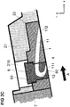
- FIG. 3C shows a further embodiment of a structural assembly in the region of a row of blades with running gap in the meridian view (xr).
- this embodiment is different from the embodiments of FIGS. 3A and 3B provided that the replaceable plug 6 penetrates only the insert member 22 and is fitted in this. A structural member penetrating the plug 6 is thus provided solely by the insert member 22.
- the support member 21 has a local recess 215, for example in the form of a mounting opening through which the replaceable plug 6 in the insert member 22 can be mounted and dismounted. It can be provided, for example, that the plug 6 has a round cross section and is fixed by means of a thread 63 in its upper part in the insert member 22.
- the shape and fixation modes of the replaceable plug 6 may be formed in other ways.
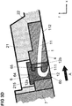
- the Figure 3D shows a further embodiment of a structural assembly in the region of a row of blades with running gap in the meridian view (xr).
- the replaceable plug 6 penetrates again alone the insert member 22, wherein above the plug 6 in the support member 21, a mounting opening 215 is formed.
- the plug 6 is designed as a multi-part element with two partial plugs 64, 65, whereby more than two partial plugs can be provided.
- the subdivision of the plug 6 into two sub-plugs 64, 65 takes place here along two sections of the secondary flow channel 1, that is, each of the two sub-plugs 64, 65 accommodates a lower portion 12a, 12b of the portion 12 realized in the plug 6. This is associated with the advantage in that the secondary flow channel 1 can be made more easily accessible, for example, to a production tool.
- the exchangeable plug 6 may be provided to produce the exchangeable plug 6 by means of a casting, sintering or print production method. This applies to all described embodiments.
- FIG. 3E shows a further embodiment of a structural assembly in the region of a row of blades with running gap in the meridian view (xr).
- the secondary flow channel 1 comprises three subsections 11, 12, 13, wherein a subsection is formed in a support member 21, a subsection in a replaceable plug 6, and a subsection in a connection component 23.
- the support member 21 forms with a part of its surfaces a part of the main flow path boundary 4. At the side facing away from the main flow path, it forms a structure 212 for receiving the replaceable plug 6, which is formed by a cylindrical wall or a nozzle 212 in the illustrated embodiment.
- the end face 60 of the plug 6 is a part of the Hauptströmungspfadberandung 4.
- a portion 12 of the secondary flow channel and one of the openings 111 of the secondary flow channel are integrated.
- the support member 21 further includes on its side facing away from the main flow path side a web 211, in which a first portion 13 of the secondary flow channel is formed. Between the web 211 and the neck or the wall 212 extends the connecting member 22 which extends on the side facing away from the main flow path side of the support member 21 between these portions 211, 212 of the support member 21 and is arranged, for example as a line freely in space.
- a fixation of the replaceable plug 6 can be realized for example by a fit, a press fit, a plug, a clamp or a screw.
- the connecting member 11 is attached to the web 211 and the nozzle 212, for example, by a fit, a plug, a clamp, a screw, a weld or a solder.
- the connecting member 23 is formed such that it is inserted in recesses in the support member 21 in the region of at least one end of the secondary flow channel and in this way has surfaces which form part of the Hauptströmungspfadberandung 4.
- the connecting piece 211 is formed as part of the connecting component 23.
- FIGS. 3A to 3E the constructive solutions, with regard to FIGS. 3A to 3E are described, combined with each other.
- a multipart plug 6 in the embodiment of the FIG. 3E be realized.
- the invention is not limited in its embodiment to the embodiments shown above, which are to be understood only as examples.
- shape and configuration of the secondary flow channels and of the components providing them can be realized in a different way than illustrated.
Landscapes
- Engineering & Computer Science (AREA)
- Mechanical Engineering (AREA)
- General Engineering & Computer Science (AREA)
- Structures Of Non-Positive Displacement Pumps (AREA)
Description
- Die Erfindung betrifft eine Strukturbaugruppe für eine Strömungsmaschine gemäß dem Oberbegriff des Patentanspruchs 1.
- Die aerodynamische Belastbarkeit und die Effizienz von Strömungsmaschinen, im Besonderen von Strömungsarbeitsmaschinen wie Bläsern, Verdichtern, Pumpen und Ventilatoren, wird durch das Wachstum und die Ablösung von Grenzschichten im Rotorund Statorspitzenbereich nahe der Gehäuse- beziehungsweise Nabenwand begrenzt. Dies führt bei Schaufelreihen mit Laufspalt bei höherer Belastung zu hohen Sekundärverlusten und ggf. zum Auftreten von Betriebsinstabilitäten.
- Als Gegenmaßnahme ist es bekannt, sogenannte Casing Treatments einzusetzen. Die einfachste Form von Casing Treatments sind Umfangsnuten mit rechteckigem oder parallelogrammförmigem Querschnitt, wie sie beispielsweise in
EP 0 754 864 A1 offenbart sind. Andere Lösungen sehen Reihen von Schlitze oder Öffnungen im Gehäuse vor, wobei die einzelnen Schlitze/Öffnungen im Wesentlichen in Strömungsrichtung orientiert sind und eine schlanke Form mit einer in Umfangsrichtung der Maschine betrachtet geringen Ausdehnung besitzen. Solche Lösungen sind beispielsweise in derDE 101 35 003 C1 offenbart. - Weitere Casing Treatments sind als Ring am gesamten Umfang im Bereich eines Rotors im Gehäuse vorgesehen, wobei oftmals Leitschaufeln zur Reduzierung des Strömungsdralls innerhalb des Casing Treatments vorgesehen sind; so beispielsweise in den Druckschriften
EP 0 497 574 A1 ,US 2005-0226717 A1 ,US 6 585 479 B2 ,US 2005-0226717 A1 undDE 103 30 084 A1 . - Existierende Konzepte von Casing Treatments in Form von Schlitzen und/oder Kammern in der Ringkanalwand bieten eine Steigerung der Stabilität der Strömungsarbeitsmaschine. Die wird jedoch aufgrund der ungünstig gewählten Anordnung oder Formgebung nur bei Verlust an Wirkungsgrad erzielt. Bekannte Lösungen nehmen zudem einen großen Bauraum an der Peripherie des Ringkanals der Strömungsarbeitsmaschine ein, sie sind aufgrund ihrer Form (z. B. einfache parallelogrammförmige Umfangsgehäusenuten) nur bedingt wirksam und sie sind stets im Gehäuse im Bereich einer Rotorschaufelreihe vorgesehen. Casing Treatments nach dem Stand der Technik sind darauf ausgerichtet, dass sie mit Hilfe zumeist spanender Bearbeitung einfach von einer zugänglichen Seite in das Gehäuse eingebracht werden können.
- Als weitere Gegenmaßnahme gegen Sekundärverluste und das Auftreten von Betriebsinstabilitäten ist es bekannt, Injektorsysteme einzusetzen. So ist es aus der
US 8 152 445 B2 bekannt, mittels eines Düsensystems Fluid aus einer Fluidversorgungskammer in den Strömungskanal zu leiten. DieFIG. 1 zeigt die in derUS 8 152 445 B2 beschriebene Lösung. Nachteilig muss bei dieser Lösung ein komplexes Sekundärströmungskanalsystem zur Injektion von Fluid im Bereich des Gehäuses oder der Nabe durch besondere konstruktive und fertigungstechnische Maßnahmen bereitgestellt werden. - Aus der
DE 10 2008 037 154 A1 ist eine Strömungsarbeitsmaschine bekannt, die im Bereich der Schaufelvorderkante in einer Hauptströmungspfadberandung mindestens einen Sekundärströmungskanal ausbildet, der zwei an der Hauptströmungspfadberandung angeordnete Öffnungen miteinander verbindet. Jeder Sekundärströmungskanal verbindet dabei jeweils eine Entnahmeöffnung mit einer weiter stromauf vorgesehenen Zufuhröffnung. Durch die Bereitstellung solcher Sekundärströmungskanäle kann in wirkungsvoller Weise eine Grenzschichtbeeinflussung im Schaufelspitzenbereich erfolgen und dadurch eine Steigerung der Stabilität einer Strömungsarbeitsmaschine erreicht werden, ohne dass ein aufwändiges Casing Treatment am gesamten Gehäuseumfang im Bereich eines Rotors erforderlich ist. Jedoch können komplexe Sekundärströmungskanäle im Bereich des Gehäuses oder der Nabe nur durch besondere konstruktive und fertigungstechnische Maßnahmen realisiert werden. - Die
US 2012/0201654 A1 beschreibt eine Strukturbaugruppe für eine Strömungsmaschine gemäß dem Oberbegriff das Anspruchs 1. Es sind als Strukturbauteile ein inneres Gehäuseteil und ein äußeres Gehäuseteil vorgesehen. In dem inneren Gehäuseteil ist eine Aussparung vorgesehen, in die ein Luftzuführelement einsetzbar ist. Das Luftzuführelement ist dabei fest zwischen den beiden Gehäuseteilen verbaut. - Der vorliegenden Erfindung liegt die Aufgabe zu Grunde, eine Strukturbaugruppe zur Verfügung zu stellen, die in effizienter Weise Sekundärströmungskanäle, auch solche komplexer Form, im Bereich einer Hauptströmungspfadberandung einer Strömungsmaschine (d.h. im Bereich des Gehäuses oder der Nabe) bereitstellen kann.
- Diese Aufgabe wird erfindungsgemäß durch eine Strukturbaugruppe mit den Merkmalen des Anspruchs 1 und eine Strömungsmaschine mit den Merkmalen des Anspruchs 15 gelöst. Ausgestaltungen der Erfindung sind in den Unteransprüchen angegeben.
- Danach ist erfindungsgemäß vorgesehen, dass die Strukturbaugruppe mindestens ein Stützbauteil und mindestens einen direkt oder indirekt mit dem Stützbauteil verbundenen, austauschbaren Stopfen aufweist. So ist der Stutzen beispielsweise direkt mit dem Stützbauteil verbunden, z.B. am Umfang des Stützbauteils angeordnet, oder ist der Stutzen mit einem mit dem Stützbauteil verbundenen Bauteil und damit indirekt mit dem Stützbauteil verbunden. Es ist weiter erfindungsgemäß vorgesehen, dass der austauschbare Stopfen einen Teilabschnitt eines Sekundärströmungskanals umfasst, wobei der Teilabschnitt mindestens einen weiteren Teilabschnitt des Sekundärströmungskanals, der sich außerhalb des Stopfens in der Strukturbaugruppe erstreckt, zu einem zwischen seinen Öffnungen durchgängigen Sekundärströmungskanal ergänzt.
- Die erfindungsgemäße Lösung ist mit dem Vorteil verbunden, dass durch Austausch des Stopfens der Sekundärströmungskanal unterbrochen oder variiert werden kann. Auch kann im Falle eines Verschleißes ein im Stopfen ausgebildeter Teilabschnitt des Sekundärströmungskanals in einfacher Weise ausgewechselt werden. Im Stopfen können gleichzeitig räumlich kompakte und robuste dreidimensionale Strukturen eines Sekundärströmungskanals bereitgestellt werden.
- Die Erfindung betrachtet somit einen Abschnitt des Hauptströmungspfades einer Strömungsmaschine, im Bereich einer Schaufelreihe mit freiem Ende und Laufspalt, in dem eine Reihe von in Umfangsrichtung verteilten Sekundärströmungskanälen vorgesehen ist. Der Verlauf der Sekundärströmungskanäle kann jeweils räumlich komplex sein. Erfindungsgemäß wird eine Strukturbaugruppe zur konstruktiven Realisierung der genannten Sekundärströmungskanäle bereitgestellt.
- In einer Ausgestaltung der Erfindung ist vorgesehen, dass der austauschbare Stopfen wenigstens ein den Hauptströmungspfad berandendes Strukturbauteil durchdringt, welches das Stützbauteil oder ein weiteres Bauteil ist.
- In einer weiteren Ausgestaltung der Erfindung ist vorgesehen, dass das Stützbauteil mit wenigstens einem Teil seiner Flächen wenigstens einen Teil der Hauptströmungspfadberandung bildet. Auch kann vorgesehen sein, dass der austauschbare Stopfen sich in im Wesentlichen radialer Richtung bezogen auf den Hauptströmungspfad erstreckt und eine Stirnfläche ausbildet, die einen Teil der Hauptströmungspfadberandung bildet. Gemäß einer Ausführungsvariante ist dabei in der Stirnfläche des austauschbaren Stopfens wenigstens eine der Öffnungen des Sekundärströmungskanals ausgebildet.
- Gemäß einer Ausgestaltung der Erfindung ist mindestens ein Teilabschnitt eines Sekundärströmungskanals im Stützbauteil realisiert, so dass zumindest das Stützbauteil und der Stopfen Teilabschnitte des Sekundärströmungskanals beherbergen. Weitere Teilabschnitte können durch weitere Bauteile bereitgestellt werden.
- Gemäß einer Ausgestaltung der Erfindung ist das Stützbauteil als Ringgehäuse oder als Halbschalengehäuse einer Strömungsmaschine ausgebildet, oder ist das Stützbauteil ringartig oder halbringartig an der Nabe einer Strömungsmaschine ausgebildet.
- Das Stützbauteil ist erfindungsgemäß konstruktiv so beschaffen, dass zwecks Montage und Demontage des austauschbaren Stopfens von der dem Hauptströmungspfad abgewandten Seite ein direkter Zugang zum austauschbaren Stopfen gegeben ist, so dass der austauschbare Stopfen von der dem Hauptströmungspfad abgewandten Seite des Stützbauteils ohne Demontage anderer Strukturbauteile ersetzbar ist.
- In einer weiteren Ausführungsvariante umfasst die erfindungsgemäße Strukturbaugruppe des Weiteren mindestens ein Einsatzbauteil, wobei im Stützbauteil eine in Umfangsrichtung verlaufende Aussparung vorgesehen ist, die entlang des Umfangs mindestens ein Einsatzbauteil aufnimmt, und wobei jedes Einsatzbauteil mit einem Teil seiner Flächen einen Teil der Hauptströmungspfadberandung bildet und wenigstens einen Teilabschnitt eines Sekundärströmungskanals ausbildet.
- Dabei kann vorgesehen sein, dass das Einsatzbauteil am Umfang von wenigstens einem austauschbaren Stopfen gänzlich durchdrungen wird, derart, dass die Stirnfläche des austauschbaren Stopfens einen Teil der Hauptströmungspfadberandung bildet. Auch kann vorgesehen sein, dass der austauschbare Stopfen nur das Einsatzbauteil durchdringt und dort einen definierten Sitz hat, wobei das Stützbauteil eine örtliche
- Ausnehmung besitzt, durch die der austauschbare Stopfen im Einsatzbauteil montierbar und demontierbar ist. Alternativ durchdringt der austauschbare Stopfen sowohl das Stützbauteil als auch das Einsatzbauteil.
- Gemäß einer Ausgestaltung der Erfindung umfasst die erfindungsgemäße Strukturbaugruppe des Weiteren mindestens ein Verbindungsbauteil, wobei sich das Verbindungsbauteil im Wesentlichen auf der dem Hauptströmungspfad abgewandten Seite des Stützbauteils an das Stützbauteil anschließt, und wobei das Verbindungsbauteil wenigstens einen Teilabschnitt eines Sekundärströmungskanals ausbildet.
- Es kann vorgesehen sein, dass das Stützbauteil am Umfang von wenigstens einem austauschbaren Stopfen gänzlich durchdrungen wird, derart, dass die Stirnfläche des austauschbaren Stopfens einen Teil der Hauptströmungspfadberandung bildet, wobei Teilabschnitte eines Sekundärströmungskanals im Stützbauteil, im Verbindungsbauteil und im austauschbaren Stopfen ausgebildet sind und sich gegenseitig zu einem durchgehenden Sekundärströmungskanal ergänzen.
- Eine weitere Erfindungsvariante sieht vor, dass das Verbindungsbauteil im Bereich wenigstens eines Endes des Sekundärströmungskanals in Ausnehmungen im Stützbauteil eingebaut ist und auf diese Weise direkt an den Hauptströmungspfad grenzt. Bei dieser Ausführungsvariante bildet das Verbindungsbauteil somit auch einen öffnungsnahen Bereich des Sekundärströmungskanals aus.
- Zur Aufnahme und Befestigung des austauschbaren Stopfens kann an der dem Hauptströmungspfad abgewandten Seite des Stützbauteils am Umfang des Stützbauteils mindestens ein Stutzen ausgebildet sein ist. Auch kann an der dem Hauptströmungspfad abgewandten Seite des Stützbauteils wenigstens ein, wenigstens entlang eines Teils des Umfangs durchgehend verlaufender Steg zur Aufnahme mindestens eines austauschbaren Stopfens ausgebildet ist.
- Eine weitere Erfindungsvariante sieht vor, dass der austauschbare Stopfen als mehrteiliges Element ausgebildet ist. Hierzu sieht eine Ausführungsvariante vor, dass der austauschbare Stopfen entlang von wenigstens Teilabschnitten des Sekundärströmungskanals in Teilstopfen unterteilt ist. Hierzu sieht eine weitere Ausführungsvariante vor, dass der austauschbare Stopfen zweiteilig ausgebildet ist und einen fixierenden Oberstopfen und einen z.B. mit einem definiertem Sitz vorgesehenen Unterstopfen umfasst, wobei Ober- und Unterstopfen gemeinsam den austauschbarer Stopfen bilden.
- Gemäß einer Ausführungsvariante ist die Fixierung des austauschbaren Stopfens durch eine Passung, eine Presspassung, eine Steckung, eine Klemmung oder eine Verschraubung realisiert.
- Der austauschbare Stopfen mit implementiertem Teilabschnitt eines Sekundärströmungskanals kann zum Zweck einer Unterbindung einer Strömung durch den Sekundärströmungskanal durch einen Blindstopfen ohne implementierten Kanal ersetzt werden.
- Die vorliegende Erfindung bezieht sich allgemein auf Strukturbaugruppen für Strömungsmaschinen wie Turbinen, und in besonderen Strömungsarbeitsmaschinen wie Bläser, Verdichter, Pumpen und Ventilatoren, sowohl in axialer, halbaxialer als auch in radialer Bauart. Das Arbeitsmedium oder Fluid kann gasförmig oder flüssig sein. Die Strömungsmaschine kann eine oder mehrere Stufen mit jeweils einem Rotor und einem Stator umfassen. In Einzelfällen wird die Stufe lediglich durch einen Rotor gebildet.
- Der Rotor einer Strömungsmaschine, in der eine erfindungsgemäße Strukturbaugruppe eingesetzt wird, besteht aus einer Anzahl von Schaufeln, die mit der rotierenden Welle der Strömungsmaschine verbunden sind und im Fall der Strömungsarbeitsmaschine Energie an das Arbeitsmedium abgeben. Der Rotor kann mit oder ohne Deckband am äußeren Schaufelende ausgeführt sein.
- Der Stator einer Strömungsmaschine, in der eine erfindungsgemäße Strukturbaugruppe eingesetzt wird, besteht aus einer Anzahl feststehender Schaufeln, die nabenseitig wie gehäuseseitig mit festem oder freiem Schaufelende ausgeführt sein können.
- Die Rotortrommel und die Beschaufelung sind üblicherweise von einem Gehäuse umgeben. In anderen Fällen, z. B. bei Propellern oder Schiffsschrauben, existiert kein Gehäuse.
- Eine Strömungsmaschine, in der eine erfindungsgemäße Strukturbaugruppe eingesetzt wird, kann auch einen Stator vor dem ersten Rotor, ein sogenanntes Vorleitrad, aufweisen. Mindestens ein Stator oder Vorleitrad kann - abweichend von einer unbeweglichen Fixierung - drehbar gelagert sein, um den Anstellwinkel verändern zu können. Eine Verstellung erfolgt beispielsweise durch eine von außerhalb des Ringkanals zugängliche Spindel.
- In einer Ausgestaltung kann eine Strömungsmaschine, in der eine erfindungsgemäße Strukturbaugruppe eingesetzt wird, mindestens eine Reihe verstellbarer Rotoren aufweisen.
- In einer Ausgestaltung kann eine Strömungsmaschine, in der eine erfindungsgemäße Strukturbaugruppe eingesetzt wird, bei Mehrstufigkeit zwei gegenläufige Wellen besitzen, so daß die Rotorschaufelreihen von Stufe zu Stufe die Drehrichtung wechseln. Hierbei existieren keine Statoren zwischen aufeinander folgenden Rotoren.
- In einer Ausgestaltung kann eine Strömungsmaschine, in der eine erfindungsgemäße Strukturbaugruppe eingesetzt wird, eine Nebenstromkonfiguration derart aufweisen, daß sich ein einstromiger Ringkanal hinter einer bestimmten Schaufelreihe in zwei konzentrische Ringkanäle aufteilt, die ihrerseits mindestens jeweils eine weitere Schaufelreihe beherbergen.
- Bei der Strömungsmaschine, in der eine erfindungsgemäße Strukturbaugruppe eingesetzt wird, handelt es sich beispielsweise um ein Strahltriebwerk, insbesondere ein Turbofan-Triebwerk. Die Strukturbaugruppe ist beispielsweise im Bereich eines Verdichters eines Strahltriebwerks bzw. Turbofan-Triebwerk ausgebildet.
- Die Erfindung betrifft des Weiteren eine Strömungsarbeitsmaschine mit einer erfindungsgemäßen Strukturbaugruppe.
- Die Erfindung wird nachfolgend unter Bezugnahme auf die Figuren der Zeichnung anhand mehrerer Ausführungsbeispiele näher erläutert. Es zeigen:
- Fig. 1
- ein Rotorgehäuse mit einer integrierten Düse zur Injektion von Fluid in einen Laufspalt gemäß dem Stand der Technik;
- Fig. 2A
- ein Ausführungsbeispiel eines Rotorgehäuses einer Strömungsmaschine mit einem Sekundärströmungskanal in einem Meridianschnitt;
- Fig. 2B
- ein Ausführungsbeispiel eines Rotorgehäuses einer Strömungsmaschine mit einem Sekundärströmungskanal in räumlicher Ansicht;
- Fig. 3A
- ein erstes Ausführungsbeispiel einer Strukturbaugruppe für eine Strömungsmaschine, die einen Sekundärströmungskanal ausbildet;
- Fig. 3B
- ein zweites Ausführungsbeispiel einer Strukturbaugruppe für eine Strömungsmaschine, die einen Sekundärströmungskanal ausbildet;
- Fig. 3C
- ein drittes Ausführungsbeispiel einer Strukturbaugruppe für eine Strömungsmaschine, die einen Sekundärströmungskanal ausbildet.
- Fig. 3D
- ein viertes Ausführungsbeispiel einer Strukturbaugruppe für eine Strömungsmaschine, die einen Sekundärströmungskanal ausbildet; und
- Fig. 3E
- ein fünftes Ausführungsbeispiel einer Strukturbaugruppe für eine Strömungsmaschine, die einen Sekundärströmungskanal ausbildet.
- Die Lehre gemäß dem Stand der Technik, mittels eines Düsensystems Fluid aus einer Fluidversorgungskammer in einen Strömungskanal zu injizieren, war eingangs anhand der
Figur 1 beschrieben worden. - Die
Fig. 2A zeigt eine Anordnung einer Schaufelreihe 3 mit freiem Ende und Laufspalt 5 in der durch die Axialrichtung x und die Radialrichtung r gebildeten Meridianebene. Der Laufspalt 5 trennt die Schaufelspitze von einem zum Hauptströmungspfad gehörenden Bauteil 2 an der Nabe oder dem Gehäuse der Strömungsarbeitsmaschine. Das Bauteil 2 bildet dabei zum Hauptströmungspfad hin eine Hauptströmungspfadberandung 4 aus. - Zwischen der Schaufelspitze und dem zum Hauptströmungspfad gehörenden Bauteil 2 liegt eine rotierende Relativbewegung vor. Die Darstellung gilt somit gleichermaßen für folgende Anordnungen: 1.) rotierende Schaufel an stehendem Gehäuse; 2.) ruhende Schaufel an rotierender Nabe; 3.) ruhende Schaufel an rotierendem Gehäuse; und 4.) rotierende Schaufel an stehender Nabe.
- Die Hauptströmungsrichtung im Hauptströmungspfad ist mit einem Pfeil A gekennzeichnet. Stromauf und/oder stromab der Schaufelreihe 3 mit Laufspalt können sich weitere Schaufelreihen befinden. Innerhalb des zum Hauptströmungspfad gehörenden Bauteils 2 ist im Bereich des Laufspaltes 5 eine Reihe von am Umfang verteilten Sekundärströmungskanälen 1 vorgesehen, die an ihren Enden jeweils eine Öffnung ausbilden (Zuführöffnung und Entnahmeöffnung).
- Die Öffnungen der Sekundärströmungskanäle befinden sich an der Hauptströmungspfadberandung 4. Die
Fig. 2A zeigt den Umriss beziehungsweise die Projektion eines einzelnen Sekundärströmungskanals 1 in der Meridianebene (x-r). In räumlicher Betrachtung besitzt jeder Kanal 1 einen dreidimensionalen räumlich verwundenen Verlauf, der in derFig. 2B beispielhaft dargestellt ist. - Es wird darauf hingewiesen, dass die Querschnittsform der Sekundärströmungskanäle 1 in der
Fig. 2B lediglich beispielhaft als rechteckig angegeben ist. Beispielsweise kann der Querschnitt der Sekundärströmungskanäle 1 in anderen Ausführungsvarianten ohne Ecken, insbesondere kreisförmig oder elliptisch ausgebildet sein. - Die
Figur 3A zeigt eine erfindungsgemäße Strukturbaugruppe im Bereich einer Schaufelreihe mit Laufspalt in der Meridianansicht (x-r). Die Hauptströmungsrichtung ist mit einem Pfeil A gekennzeichnet. Die Schaufelreihe ist zu Gunsten einer einfacheren Darstellung nicht mehr gezeigt. - In der Strukturbaugruppe ist mindestens ein Sekundärströmungskanal 1 ausgebildet, der zwei Öffnungen 111, 112 in der Hauptströmungspfadberandung 4 aufweist und über diese mit dem Hauptströmungspfad verbunden ist. Dabei wird darauf hingewiesen, dass in dem Ausführungsbeispiel der
Figur 3A der Sekundärströmungskanal 11 als einpfadiger Pfad ausgeführt ist mit einer Öffnung, durch die Fluid aus dem Hauptströmungskanal in den Sekundärströmungskanal 1 einströmt und einer zweiten Öffnung, durch die Fluid den Sekundärströmungskanal 1 verlässt. Durch welche der Öffnungen 111, 112 Fluid einströmt und durch welche der Öffnungen 111, 112 Fluid ausströmt, hängt dabei von der genauen Positionierung der Öffnungen 111, 112 im Hinblick auf die Schaufeln der Schaufelreihe 3 (vgl.Fig. 2B ) ab. - In alternativen Ausgestaltungen kann vorgesehen sein, dass mindestens einer der Sekundärströmungskanäle durch eine Anordnung gebildet ist, bei der sich ein Einzelkanal entlang seines Verlaufes in wenigstens zwei Teilkanäle aufteilt und dadurch eine Art "Hosenkonfiguration" bildet. Für diesen Fall sind eine Einströmöffnung und mehrere Ausströmöffnungen vorgesehen, die zu dem Sekundärströmungskanal gehören. Gemäß einer weiteren alternativen Ausgestaltung kann vorgesehen sein, dass mindestens einer der Sekundärströmungskanäle durch eine Anordnung gebildet ist, bei der wenigstens zwei Kanäle zu einem Kanal zusammengeführt werden, wobei dann mehrere Einströmöffnungen und eine Ausströmöffnung zu dem Sekundärströmungskanal gehören.
- Gemäß der
Figur 3A ist der Sekundärströmungskanal 1 in einer Strukturbaugruppe realisiert, die ein Stützbauteil 21, ein Einsatzbauteil 22 und einen austauschbaren Stopfen 6 umfasst. - Das Stützbauteil 21 dient der strukturellen Realisierung im Bereich der inneren oder äußeren Hauptströmungspfadberandung und kann zum außen liegenden Gehäuse oder zur innen liegenden Nabe der Strömungsmaschine gehören. Es kann vorgesehen sein, dass es mit einem Teil seiner Flächen einen Teil der Hauptströmungspfadberandung 4 bildet. Im dargestellten Ausführungsbeispiel stellt das Stützbauteil 21 einen Teil des außen liegenden Gehäuses der Strömungsmaschine dar. Grundsätzlich kann das Stützbauteil 21 insbesondere Bestandteil der Strömungsmaschinenkonstruktion in folgenden Bereichen sein:
- Bestandteil eines ein- oder mehrschaligen Gehäuses von Schaufelreihen oder Stufen mit fester Schaufelgeometrie;
- Bestandteil eines ein- oder mehrschaligen Gehäuses von Schaufelreihen oder Stufen mit verstellbarer Schaufelgeometrie;
- Bestandteil von Rotortrommeln, Rotorscheiben oder Blisk-Modulen;
- Bestandteil von Innendeckbandbaugruppen im Nabenbereich von Leitradschaufeln.
- Im Ausführungsbeispiel der
Figur 3A ist das Stützbauteil 21 als Ringgehäuse einer Strömungsmaschine oder als Halbschalengehäuse einer Strömungsmaschine ausgebildet. Bei einer entsprechenden Anordnung im Nabenbereich ist es beispielsweise ringartig an der Nabe einer Strömungsmaschine oder halbringartig an der Nabe einer Strömungsmaschine ausgebildet. - Im Stützbauteil 21 ist eine in der Umfangsrichtung verlaufende Aussparung vorgesehen, in die entlang des Umfangs mindestens ein Einsatzbauteil 22 eingesetzt ist. Das Einsatzbauteil 21 bildet dabei mit einem Teil seiner Flächen einen Teil der Hauptströmungspfadberandung 4.
- Der austauschbare Stopfen 6 erstreckt sich bezogen auf den Hauptströmungspfad in im Wesentlichen radialer Richtung, wobei er sowohl das Stützbauteil 21 als auch das Einsatzbauteil 22 durchdringt. Der Stopfen 6 besitzt eine Stirnfläche 60, der einen Teil der Hauptströmungspfadberandung 4 bildet.
- Der Sekundärströmungskanal 1 umfasst zwei Teilabschnitte 11, 12, wobei der eine Teilabschnitt 11 im Einsatzbauteil 22 und der andere Teilabschnitt 12 im austauschbaren Stopfen 6 ausgebildet ist. Die Teilabschnitte 11, 12 im Einsatzbauteil 22 und im austauschbaren Stopfen 6 ergänzen sich dabei zu einem durchgehenden Sekundärströmungskanal 1. Die eine der beiden Öffnungen 111, 112 des Sekundärströmungskanals 1 ist im Einsatzbauteil 22 und die andere der Öffnungen 111, 112 des Sekundärströmungskanals 1 ist im Stopfen 6 ausgebildet.
- Es wird darauf hingewiesen, dass im Ausführungsbeispiel der
Figur 3A das Einsatzbauteil 22 in axialer Richtung in die entsprechende Aussparung im Stützbauteil 21 eingeschoben ist. Eine Fixierung der Bauteile 21, 22 zueinander in axialer Richtung kann dabei durch ein weiteres Bauteil 7 erfolgen. - Weiter wird darauf hingewiesen, dass der Teilabschnitt 12 des Sekundärströmungskanals 1 mittels innenliegender Flächen des Stopfens 6 bereitgestellt ist, also nicht mittels an der Außenseite des Stopfens 6 ausgebildeter Strukturen.
- Die Ausbildung eines Teilabschnitts 12 des Sekundärströmungskanals 1 in einem austauschbaren Stopfen 6 ist mit dem Vorteil verbunden, dass es durch Ersetzen des Stopfens 6 durch einen Blindstopfen ohne integrierten Kanalabschnitt möglich ist, die Strömung durch den Sekundärströmungskanal 1 zu unterbinden. Mittels des austauschbaren Stopfens 6 kann somit eine Strömung durch einen Sekundärströmungskanal ein- und ausgeschaltet werden. Auch ist es möglich, verschiedene Stopfen 6 bereitzuhalten, in denen der im Stopfen 6 realisierte Teilabschnitt 12 in unterschiedlicher Weise ausgebildet ist, wobei jeweils in anderer Weise eine Ergänzung zu dem im Einsatzbauteil 22 ausgebildeten Teilabschnitt 11 erfolgt. Auf diese Weise können in einfacher Weise die Ausbildung des Sekundärströmungskanals 1 und die darin erfolgende Strömung variiert werden.
- Die
Figur 3B zeigt ein weiteres Ausführungsbeispiel einer Strukturbaugruppe im Bereich einer Schaufelreihe mit Laufspalt in der Meridianansicht (x-r). Das Ausführungsbeispiel derFigur 3B unterscheidet sich vom Ausführungsbeispiel derFigur 3A dadurch, dass der austauschbare Stopfen 6 als mehrteiliges Element ausgebildet ist. So ist der Stopfen 6 in zwei Teilstopfen 61, 62 unterteilt, wobei grundsätzlich auch mehr als zwei Teilstopfen möglich sind. Gemäß derFigur 3B umfasst der Stopfen 6 einen fixierenden Oberstopfen 62 und einen mit einem guten Pass-Sitz versehenen Unterstopfen 61. Dabei ist der Teilbereich 12 des Sekundärströmungskanals 1 in dem Unterstopfen 61 ausgebildet. Der Oberstopfen 62 ist beispielsweise durch Verschrauben oder dergleichen in einer entsprechenden Öffnung des Stützbauteils 21 fixiert. -
Figur 3C zeigt ein weiteres Ausführungsbeispiel einer Strukturbaugruppe im Bereich einer Schaufelreihe mit Laufspalt in der Meridianansicht (x-r). Bei dieser Ausgestaltung ist abweichend von den Ausgestaltungen derFiguren 3A und3B vorgesehen, dass der austauschbare Stopfen 6 nur das Einsatzbauteil 22 durchdringt und in dieses eingepasst ist. Ein Strukturbauteil, das der Stopfen 6 durchdringt, wird somit allein durch das Einsatzbauteil 22 bereitgestellt. - Dabei besitzt das Stützbauteil 21 eine örtliche Ausnehmung 215, beispielsweise in Form einer Montageöffnung, durch die der austauschbare Stopfen 6 im Einsatzbauteil 22 montiert und demontiert werden kann. Dabei kann beispielsweise vorgesehen sein, dass der Stopfen 6 einen runden Querschnitt besitzt und mit Hilfe eines Gewindes 63 in seinem oberen Teil im Einsatzbauteil 22 fixiert wird. Jedoch können Form und Fixierungsarten des austauschbaren Stopfens 6 auch in anderer Weise ausgebildet sein.
- Die
Figur 3D zeigt ein weiteres Ausführungsbeispiel einer Strukturbaugruppe im Bereich einer Schaufelreihe mit Laufspalt in der Meridianansicht (x-r). Bei diesem Ausführungsbeispiel durchdringt der austauschbare Stopfen 6 wiederum allein das Einsatzbauteil 22, wobei oberhalb des Stopfens 6 in dem Stützbauteil 21 eine Montageöffnung 215 ausgebildet ist. Anders als im Ausführungsbeispiel derFigur 3C ist der Stopfen 6 als mehrteiliges Element mit zwei Teilstopfen 64, 65 ausgebildet, wobei auch mehr als zwei Teilstopfen vorgesehen werden können. Die Unterteilung des Stopfens 6 in zwei Teilstopfen 64, 65 erfolgt hierbei entlang zweier Abschnitte des Sekundärströmungskanals 1, das heißt, jeder der beiden Teilstopfen 64, 65 beherbergt einen Unterteilabschnitt 12a, 12b des im Stopfen 6 realisierten Teilabschnitts 12. Dies ist mit dem Vorteil verbunden, dass der Sekundärströmungskanal 1 beispielsweise einem Fertigungswerkzeug einfacher zugänglich gemacht werden kann. - Aufgrund der eventuell bestehenden Komplexität der Sekundärströmungskanäle im Hinblick auf ihre dreidimensionale Form kann vorgesehen sein, den austauschbaren Stopfen 6 mit Hilfe eines Gieß-, Sinter- oder Print-Fertigungsverfahrens herzustellen. Dies gilt für sämtliche beschriebene Ausführungsbeispiele.
- Die
Figur 3E zeigt ein weiteres Ausführungsbeispiel einer Strukturbaugruppe im Bereich einer Schaufelreihe mit Laufspalt in der Meridianansicht (x-r). Bei diesem Ausführungsbeispiel umfasst der Sekundärströmungskanal 1 drei Teilabschnitte 11, 12, 13, wobei ein Teilabschnitt in einem Stützbauteil 21, ein Teilabschnitt in einem austauschbaren Stopfen 6 und ein Teilabschnitt in einem Verbindungsbauteil 23 ausgebildet ist. - Das Stützbauteil 21 bildet mit einem Teil seiner Flächen einen Teil der Hauptströmungspfadberandung 4. An der dem Hauptströmungspfad abgewandten Seite bildet es eine Struktur 212 zur Aufnahme des austauschbaren Stopfens 6 aus, die im dargestellten Ausführungsbeispiel durch eine zylinderförmige Wandung bzw. einen Stutzen 212 gebildet ist. In die Wandung 212 ist der Stopfen 6 eingesetzt, wobei die Stirnfläche 60 des Stopfens 6 einen Teil der Hauptströmungspfadberandung 4 darstellt. In dem Stopfen 6 sind ein Teilabschnitt 12 des Sekundärströmungskanals sowie eine der Öffnungen 111 des Sekundärströmungskanals integriert.
- Das Stützbauteil 21 weist des Weiteren auf seiner dem Hauptströmungspfad abgewandten Seite einen Steg 211 auf, in dem ein erster Abschnitt 13 des Sekundärströmungskanals ausgebildet ist. Zwischen dem Steg 211 und dem Stutzen bzw. der Wandung 212 verläuft das Verbindungsbauteil 22, das sich auf der dem Hauptströmungspfad abgewandten Seite des Stützbauteils 21 zwischen diesen Teilbereichen 211, 212 des Stützbauteils 21 erstreckt und beispielsweise als Leitung frei im Raum angeordnet ist.
- Eine Fixierung des austauschbaren Stopfens 6 kann beispielsweise durch eine Passung, eine Presspassung, eine Steckung, eine Klemmung oder eine Verschraubung realisiert sein. Das Verbindungsbauteil 11 wird beispielsweise durch eine Passung, eine Steckung, eine Klemmung, eine Verschraubung, eine Schweißung oder eine Lötung am Steg 211 und am Stutzen 212 befestigt.
- Gemäß einer alternativen Ausgestaltung ist das Verbindungsbauteil 23 derart ausgebildet, dass es im Bereich wenigstens eines Endes des Sekundärströmungskanals in Ausnehmungen im Stützbauteil 21 eingesetzt ist und auf diese Weise Flächen aufweist, die einen Teil der Hauptströmungspfadberandung 4 bilden. Beispielsweise ist in einer Abwandlung der
Figur 3E der Stutzen 211 als Teil des Verbindungsbauteils 23 ausgebildet. - In weiteren Ausgestaltungen der Erfindung können die konstruktiven Lösungen, die im Hinblick auf die
Figuren 3A bis 3E beschrieben sind, miteinander kombiniert werden. Beispielsweise kann ein mehrteiliger Stopfen 6 auch beim Ausführungsbeispiel derFigur 3E realisiert sein. - Die Erfindung beschränkt sich in ihrer Ausgestaltung nicht auf die vorstehend dargestellten Ausführungsbeispiele, die lediglich beispielhaft zu verstehen sind. Beispielsweise können Form und Ausgestaltung der Sekundärströmungskanäle sowie der diese bereitstellenden Bauteile (Stützbauteil, Verbindungsbauteil, Einsatzbauteil und Stopfen) in anderer Weise als dargestellt realisiert sein.
Claims (15)
- Strukturbaugruppe für eine Strömungsmaschine, die aufweist:- eine Hauptströmungspfadberandung (4), die einen Hauptströmungspfad einer Strömungsmaschine berandet, wobei in dem Hauptströmungspfad mindestens eine Reihe von Schaufeln (3) mit jeweils einem Schaufelende angeordnet ist, wobei ein Spalt (5) zwischen den Schaufelenden der mindestens einen Reihe von Schaufeln (3) und der Hauptströmungspfadberandung (4) besteht, und wobei die Schaufeln (3) einer Schaufelreihe und die Hauptströmungspfadberandung (4) eine rotierende Relativbewegung zueinander ausführen; und- mindestens einen Sekundärströmungskanal (1), der an in Strömungsrichtung beabstandeten Enden jeweils eine Öffnung (111, 112) aufweist, die in der Hauptströmungspfadberandung (4) ausgebildet ist, so dass der Sekundärströmungskanal (1) mittels der beiden Öffnungen (111, 112) mit dem Hauptströmungspfad verbunden ist, wobei- die Strukturbaugruppe mindestens ein Stützbauteil (21) und mindestens einen direkt oder indirekt mit dem Stützbauteil (21) verbundenen austauschbaren Stopfen (6) aufweist, und- der austauschbare Stopfen (6) einen Teilabschnitt eines Sekundärströmungskanals (1) umfasst, wobei der Teilabschnitt mindestens einen weiteren Teilabschnitt des Sekundärströmungskanals (1), der sich außerhalb des Stopfens (6) in der Strukturbaugruppe erstreckt, zu einem zwischen seinen Öffnungen (111, 112) durchgängigen Sekundärströmungskanal (1) ergänzt, dadurch gekennzeichnet, dass
das Stützbauteil (21) konstruktiv so beschaffen ist, dass zwecks Montage und Demontage des austauschbaren Stopfens (6) von der dem Hauptströmungspfad abgewandten Seite ein direkter Zugang zum austauschbaren Stopfen (6) gegeben ist, so dass der austauschbare Stopfen (6) von der dem Hauptströmungspfad abgewandten Seite des Stützbauteils (21) ohne Demontage anderer Strukturbauteile ersetzbar ist. - Baugruppe nach Anspruch 1, dadurch gekennzeichnet, dass der austauschbare Stopfen (6) wenigstens ein den Hauptströmungspfad berandendes Strukturbauteil durchdringt, welches das Stützbauteil (21) oder ein weiteres Bauteil (22) ist.
- Baugruppe nach Anspruch 1 oder 2, dadurch gekennzeichnet, dass das Stützbauteil (22) mit wenigstens einem Teil seiner Flächen wenigstens einen Teil der Hauptströmungspfadberandung (4) bildet.
- Baugruppe nach einem der vorangehenden Ansprüche, dadurch gekennzeichnet, dass der austauschbare Stopfen (6) sich in im Wesentlichen radialer Richtung bezogen auf den Hauptströmungspfad erstreckt.
- Baugruppe nach einem der vorangehenden Ansprüche, dadurch gekennzeichnet, dass der austauschbare Stopfen (6) eine Stirnfläche (60) ausbildet, die einen Teil der Hauptströmungspfadberandung (4) bildet.
- Baugruppe nach Anspruch 5, dadurch gekennzeichnet, dass in der Stirnfläche des austauschbaren Stopfens (6) wenigstens eine der Öffnungen (111, 112) des Sekundärströmungskanals (1) ausgebildet ist.
- Baugruppe nach einem der vorangehenden Ansprüche, dadurch gekennzeichnet, dass mindestens ein Teilabschnitt eines Sekundärströmungskanals (1) im Stützbauteil (21) realisiert ist.
- Baugruppe nach einem der vorangehenden Ansprüche, dadurch gekennzeichnet, dass das Stützbauteil (21) als Ringgehäuse oder als Halbschalengehäuse einer Strömungsmaschine oder ringartig oder halbringartig an der Nabe einer Strömungsmaschine ausgebildet ist.
- Baugruppe nach einem der vorangehenden Ansprüche, dadurch gekennzeichnet, dass sie des Weiteren mindestens ein Einsatzbauteil (22) umfasst, wobei im Stützbauteil (21) eine in Umfangsrichtung verlaufende Aussparung vorgesehen ist, die entlang des Umfangs mindestens ein Einsatzbauteil (22) aufnimmt, und wobei jedes Einsatzbauteil (22) mit einem Teil seiner Flächen einen Teil der Hauptströmungspfadberandung bildet und wenigstens einen Teilabschnitt eines Sekundärströmungskanals ausbildet.
- Baugruppe nach Anspruch 9, dadurch gekennzeichnet, dass der austauschbare Stopfen (6) nur das Einsatzbauteil (22) durchdringt und dort einen definierten Sitz hat, wobei das Stützbauteil (21) eine örtliche Ausnehmung (215) besitzt, durch die der austauschbare Stopfen (6) im Einsatzbauteil (22) montierbar und demontierbar ist.
- Baugruppe nach einem der vorangehenden Ansprüche, dadurch gekennzeichnet, dass sie des Weiteren mindestens ein Verbindungsbauteil (23) umfasst, wobei sich das Verbindungsbauteil (23) im Wesentlichen auf der dem Hauptströmungspfad abgewandten Seite des Stützbauteils (21) an das Stützbauteil (21) anschließt, und wobei das Verbindungsbauteil (23) wenigstens einen Teilabschnitt (11) eines Sekundärströmungskanals (1) ausbildet.
- Baugruppe nach Anspruch 11, dadurch gekennzeichnet, dass das Stützbauteil (21) am Umfang von wenigstens einem austauschbaren Stopfen (6) gänzlich durchdrungen wird, derart, dass die Stirnfläche (60) des austauschbaren Stopfens (6) einen Teil der Hauptströmungspfadberandung (4) bildet, wobei die Teilabschnitte (13, 11, 12) eines Sekundärströmungskanals im Stützbauteil (21), im Verbindungsbauteil (23) und im austauschbaren Stopfen (6) ausgebildet sind und sich gegenseitig zu einem durchgehenden Sekundärströmungskanal (1) ergänzen.
- Baugruppe nach einem der vorangehenden Ansprüche, dadurch gekennzeichnet, dass an der dem Hauptströmungspfad abgewandten Seite des Stützbauteils (21) örtlich am Umfang wenigstens ein Stutzen (212) zur Aufnahme eines austauschbaren Stopfens (6) vorgesehen ist.
- Baugruppe nach einem der vorangehenden Ansprüche, dadurch gekennzeichnet, dass der austauschbare Stopfen (6) als mehrteiliges Element ausgebildet ist.
- Strömungsmaschine mit einer Strukturbaugruppe gemäß einem der vorangehenden Ansprüche.
Applications Claiming Priority (1)
| Application Number | Priority Date | Filing Date | Title |
|---|---|---|---|
| DE102013210171.6A DE102013210171A1 (de) | 2013-05-31 | 2013-05-31 | Strukturbaugruppe für eine Strömungsmaschine |
Publications (2)
| Publication Number | Publication Date |
|---|---|
| EP2808558A1 EP2808558A1 (de) | 2014-12-03 |
| EP2808558B1 true EP2808558B1 (de) | 2017-12-06 |
Family
ID=50842103
Family Applications (1)
| Application Number | Title | Priority Date | Filing Date |
|---|---|---|---|
| EP14170065.8A Not-in-force EP2808558B1 (de) | 2013-05-31 | 2014-05-27 | Strukturbaugruppe für eine Strömungsmaschine |
Country Status (3)
| Country | Link |
|---|---|
| US (1) | US9587509B2 (de) |
| EP (1) | EP2808558B1 (de) |
| DE (1) | DE102013210171A1 (de) |
Families Citing this family (3)
| Publication number | Priority date | Publication date | Assignee | Title |
|---|---|---|---|---|
| DE102018116062A1 (de) * | 2018-07-03 | 2020-01-09 | Rolls-Royce Deutschland Ltd & Co Kg | Strukturbaugruppe für einen Verdichter einer Strömungsmaschine |
| US10876549B2 (en) | 2019-04-05 | 2020-12-29 | Pratt & Whitney Canada Corp. | Tandem stators with flow recirculation conduit |
| CN113027817A (zh) * | 2021-03-12 | 2021-06-25 | 西北工业大学 | 一种轴流压气机自循环机匣的加工方法及其结构 |
Citations (1)
| Publication number | Priority date | Publication date | Assignee | Title |
|---|---|---|---|---|
| US6447332B1 (en) * | 1999-07-05 | 2002-09-10 | Israel Aircraft Industries Ltd. | Adapter for use in EGT measurement of a jet engine |
Family Cites Families (15)
| Publication number | Priority date | Publication date | Assignee | Title |
|---|---|---|---|---|
| DE1503581B1 (de) * | 1965-05-04 | 1970-12-17 | Maschf Augsburg Nuernberg Ag | Mit Abgasturbo-Aufladung betriebene Zweitakt-Brennkraftmaschine |
| EP0497574B1 (de) | 1991-01-30 | 1995-09-20 | United Technologies Corporation | Ventilatorgehäuse mit Rezirculationskanälen |
| US5562404A (en) * | 1994-12-23 | 1996-10-08 | United Technologies Corporation | Vaned passage hub treatment for cantilever stator vanes |
| US5586859A (en) | 1995-05-31 | 1996-12-24 | United Technologies Corporation | Flow aligned plenum endwall treatment for compressor blades |
| JP3816150B2 (ja) | 1995-07-18 | 2006-08-30 | 株式会社荏原製作所 | 遠心流体機械 |
| DE10105456A1 (de) * | 2001-02-07 | 2002-08-08 | Daimler Chrysler Ag | Verdichter, insbesondere für eine Brennkraftmaschine |
| DE10135003C1 (de) | 2001-07-18 | 2002-10-02 | Mtu Aero Engines Gmbh | Verdichtergehäusestruktur |
| US6585479B2 (en) | 2001-08-14 | 2003-07-01 | United Technologies Corporation | Casing treatment for compressors |
| DE10330084B4 (de) | 2002-08-23 | 2010-06-10 | Mtu Aero Engines Gmbh | Rezirkulationsstruktur für Turboverdichter |
| GB2413158B (en) | 2004-04-13 | 2006-08-16 | Rolls Royce Plc | Flow control arrangement |
| DE102004030597A1 (de) * | 2004-06-24 | 2006-01-26 | Rolls-Royce Deutschland Ltd & Co Kg | Strömungsarbeitsmaschine mit Aussenradstrahlerzeugung am Stator |
| DE102004055439A1 (de) | 2004-11-17 | 2006-05-24 | Rolls-Royce Deutschland Ltd & Co Kg | Strömungsarbeitsmaschine mit dynamischer Strömungsbeeinflussung |
| DE102008017844A1 (de) | 2008-04-08 | 2009-10-15 | Rolls-Royce Deutschland Ltd & Co Kg | Strömungsmaschine mit Fluid-Injektorbaugruppe |
| DE102008037154A1 (de) | 2008-08-08 | 2010-02-11 | Rolls-Royce Deutschland Ltd & Co Kg | Strömungsarbeitsmaschine |
| FR2949518B1 (fr) * | 2009-08-31 | 2011-10-21 | Snecma | Compresseur de turbomachine ayant des injecteurs d'air |
-
2013
- 2013-05-31 DE DE102013210171.6A patent/DE102013210171A1/de not_active Withdrawn
-
2014
- 2014-05-27 EP EP14170065.8A patent/EP2808558B1/de not_active Not-in-force
- 2014-05-28 US US14/289,318 patent/US9587509B2/en not_active Expired - Fee Related
Patent Citations (1)
| Publication number | Priority date | Publication date | Assignee | Title |
|---|---|---|---|---|
| US6447332B1 (en) * | 1999-07-05 | 2002-09-10 | Israel Aircraft Industries Ltd. | Adapter for use in EGT measurement of a jet engine |
Also Published As
| Publication number | Publication date |
|---|---|
| EP2808558A1 (de) | 2014-12-03 |
| US20140363277A1 (en) | 2014-12-11 |
| DE102013210171A1 (de) | 2014-12-04 |
| US9587509B2 (en) | 2017-03-07 |
Similar Documents
| Publication | Publication Date | Title |
|---|---|---|
| EP2808559B1 (de) | Strukturbaugruppe für eine Strömungsmaschine | |
| EP2108784B1 (de) | Strömungsmaschine mit Fluid-Injektorbaugruppe | |
| EP2808556B1 (de) | Strukturbaugruppe für eine Strömungsmaschine | |
| EP2025945B1 (de) | Strömungsarbeitsmaschine mit Ringkanalwandausnehmung | |
| DE102007056953B4 (de) | Strömungsarbeitsmaschine mit Ringkanalwandausnehmung | |
| EP2096316B1 (de) | Gehäusestrukturierung für Axialverdichter im Nabenbereich | |
| EP1382855B1 (de) | Strömungsarbeitsmaschine mit integriertem Fluidzirkulationssystem | |
| EP2132414B1 (de) | Shiplap-anordnung | |
| EP2110559A2 (de) | Strömungsmaschine mit Fluidrückfuhr zur Grenzschichtbeeinflussung | |
| EP3287611B1 (de) | Gasturbine | |
| DE102004030597A1 (de) | Strömungsarbeitsmaschine mit Aussenradstrahlerzeugung am Stator | |
| EP3428393B1 (de) | Laufrad einer strömungsmaschine | |
| EP2921716B1 (de) | Schaufelreihengruppe | |
| EP3409899B1 (de) | Dichtungsanordnung mit angeschweisstem dichtungsblech, strömungsmaschine und herstellungsverfahren | |
| EP2818724B1 (de) | Strömungsmaschine und Verfahren | |
| EP3161325A1 (de) | Diffuser für radialverdichter | |
| EP3236011B1 (de) | Rotor mit überhang an laufschaufeln für ein sicherungselement | |
| EP2846000B1 (de) | Turbinenleitrad einer Gasturbine | |
| EP2808557A1 (de) | Strukturbaugruppe für eine Strömungsmaschine | |
| EP2808558B1 (de) | Strukturbaugruppe für eine Strömungsmaschine | |
| EP3022393B1 (de) | Rotor für eine thermische strömungsmaschine | |
| DE102012215413B4 (de) | Baugruppe einer Axialturbomaschine | |
| EP3431708A1 (de) | Umströmungsanordnung, zugehörige strömungsmaschine und verwendung | |
| EP2811117A2 (de) | Deckbandanordnung für eine Strömungsmaschine | |
| DE112020000728B4 (de) | Hochtemperaturkomponente und herstellungsverfahren für hochtemperaturkomponente |
Legal Events
| Date | Code | Title | Description |
|---|---|---|---|
| PUAI | Public reference made under article 153(3) epc to a published international application that has entered the european phase |
Free format text: ORIGINAL CODE: 0009012 |
|
| 17P | Request for examination filed |
Effective date: 20140527 |
|
| AK | Designated contracting states |
Kind code of ref document: A1 Designated state(s): AL AT BE BG CH CY CZ DE DK EE ES FI FR GB GR HR HU IE IS IT LI LT LU LV MC MK MT NL NO PL PT RO RS SE SI SK SM TR |
|
| AX | Request for extension of the european patent |
Extension state: BA ME |
|
| R17P | Request for examination filed (corrected) |
Effective date: 20150602 |
|
| RBV | Designated contracting states (corrected) |
Designated state(s): AL AT BE BG CH CY CZ DE DK EE ES FI FR GB GR HR HU IE IS IT LI LT LU LV MC MK MT NL NO PL PT RO RS SE SI SK SM TR |
|
| GRAP | Despatch of communication of intention to grant a patent |
Free format text: ORIGINAL CODE: EPIDOSNIGR1 |
|
| RIC1 | Information provided on ipc code assigned before grant |
Ipc: F04D 29/54 20060101ALN20170630BHEP Ipc: F04D 29/52 20060101AFI20170630BHEP Ipc: F04D 29/68 20060101ALI20170630BHEP |
|
| INTG | Intention to grant announced |
Effective date: 20170720 |
|
| RIN1 | Information on inventor provided before grant (corrected) |
Inventor name: DR. GUEMMER, VOLKER |
|
| GRAS | Grant fee paid |
Free format text: ORIGINAL CODE: EPIDOSNIGR3 |
|
| GRAA | (expected) grant |
Free format text: ORIGINAL CODE: 0009210 |
|
| AK | Designated contracting states |
Kind code of ref document: B1 Designated state(s): AL AT BE BG CH CY CZ DE DK EE ES FI FR GB GR HR HU IE IS IT LI LT LU LV MC MK MT NL NO PL PT RO RS SE SI SK SM TR |
|
| REG | Reference to a national code |
Ref country code: GB Ref legal event code: FG4D Free format text: NOT ENGLISH |
|
| REG | Reference to a national code |
Ref country code: AT Ref legal event code: REF Ref document number: 952645 Country of ref document: AT Kind code of ref document: T Effective date: 20171215 Ref country code: CH Ref legal event code: EP |
|
| REG | Reference to a national code |
Ref country code: IE Ref legal event code: FG4D Free format text: LANGUAGE OF EP DOCUMENT: GERMAN |
|
| REG | Reference to a national code |
Ref country code: DE Ref legal event code: R096 Ref document number: 502014006456 Country of ref document: DE |
|
| REG | Reference to a national code |
Ref country code: NL Ref legal event code: MP Effective date: 20171206 |
|
| REG | Reference to a national code |
Ref country code: LT Ref legal event code: MG4D |
|
| PG25 | Lapsed in a contracting state [announced via postgrant information from national office to epo] |
Ref country code: LT Free format text: LAPSE BECAUSE OF FAILURE TO SUBMIT A TRANSLATION OF THE DESCRIPTION OR TO PAY THE FEE WITHIN THE PRESCRIBED TIME-LIMIT Effective date: 20171206 Ref country code: NO Free format text: LAPSE BECAUSE OF FAILURE TO SUBMIT A TRANSLATION OF THE DESCRIPTION OR TO PAY THE FEE WITHIN THE PRESCRIBED TIME-LIMIT Effective date: 20180306 Ref country code: SE Free format text: LAPSE BECAUSE OF FAILURE TO SUBMIT A TRANSLATION OF THE DESCRIPTION OR TO PAY THE FEE WITHIN THE PRESCRIBED TIME-LIMIT Effective date: 20171206 Ref country code: ES Free format text: LAPSE BECAUSE OF FAILURE TO SUBMIT A TRANSLATION OF THE DESCRIPTION OR TO PAY THE FEE WITHIN THE PRESCRIBED TIME-LIMIT Effective date: 20171206 Ref country code: FI Free format text: LAPSE BECAUSE OF FAILURE TO SUBMIT A TRANSLATION OF THE DESCRIPTION OR TO PAY THE FEE WITHIN THE PRESCRIBED TIME-LIMIT Effective date: 20171206 |
|
| REG | Reference to a national code |
Ref country code: FR Ref legal event code: PLFP Year of fee payment: 5 |
|
| PG25 | Lapsed in a contracting state [announced via postgrant information from national office to epo] |
Ref country code: RS Free format text: LAPSE BECAUSE OF FAILURE TO SUBMIT A TRANSLATION OF THE DESCRIPTION OR TO PAY THE FEE WITHIN THE PRESCRIBED TIME-LIMIT Effective date: 20171206 Ref country code: BG Free format text: LAPSE BECAUSE OF FAILURE TO SUBMIT A TRANSLATION OF THE DESCRIPTION OR TO PAY THE FEE WITHIN THE PRESCRIBED TIME-LIMIT Effective date: 20180306 Ref country code: HR Free format text: LAPSE BECAUSE OF FAILURE TO SUBMIT A TRANSLATION OF THE DESCRIPTION OR TO PAY THE FEE WITHIN THE PRESCRIBED TIME-LIMIT Effective date: 20171206 Ref country code: LV Free format text: LAPSE BECAUSE OF FAILURE TO SUBMIT A TRANSLATION OF THE DESCRIPTION OR TO PAY THE FEE WITHIN THE PRESCRIBED TIME-LIMIT Effective date: 20171206 Ref country code: GR Free format text: LAPSE BECAUSE OF FAILURE TO SUBMIT A TRANSLATION OF THE DESCRIPTION OR TO PAY THE FEE WITHIN THE PRESCRIBED TIME-LIMIT Effective date: 20180307 |
|
| PG25 | Lapsed in a contracting state [announced via postgrant information from national office to epo] |
Ref country code: NL Free format text: LAPSE BECAUSE OF FAILURE TO SUBMIT A TRANSLATION OF THE DESCRIPTION OR TO PAY THE FEE WITHIN THE PRESCRIBED TIME-LIMIT Effective date: 20171206 |
|
| PG25 | Lapsed in a contracting state [announced via postgrant information from national office to epo] |
Ref country code: SK Free format text: LAPSE BECAUSE OF FAILURE TO SUBMIT A TRANSLATION OF THE DESCRIPTION OR TO PAY THE FEE WITHIN THE PRESCRIBED TIME-LIMIT Effective date: 20171206 Ref country code: CZ Free format text: LAPSE BECAUSE OF FAILURE TO SUBMIT A TRANSLATION OF THE DESCRIPTION OR TO PAY THE FEE WITHIN THE PRESCRIBED TIME-LIMIT Effective date: 20171206 Ref country code: EE Free format text: LAPSE BECAUSE OF FAILURE TO SUBMIT A TRANSLATION OF THE DESCRIPTION OR TO PAY THE FEE WITHIN THE PRESCRIBED TIME-LIMIT Effective date: 20171206 |
|
| PG25 | Lapsed in a contracting state [announced via postgrant information from national office to epo] |
Ref country code: PL Free format text: LAPSE BECAUSE OF FAILURE TO SUBMIT A TRANSLATION OF THE DESCRIPTION OR TO PAY THE FEE WITHIN THE PRESCRIBED TIME-LIMIT Effective date: 20171206 Ref country code: SM Free format text: LAPSE BECAUSE OF FAILURE TO SUBMIT A TRANSLATION OF THE DESCRIPTION OR TO PAY THE FEE WITHIN THE PRESCRIBED TIME-LIMIT Effective date: 20171206 Ref country code: RO Free format text: LAPSE BECAUSE OF FAILURE TO SUBMIT A TRANSLATION OF THE DESCRIPTION OR TO PAY THE FEE WITHIN THE PRESCRIBED TIME-LIMIT Effective date: 20171206 Ref country code: IT Free format text: LAPSE BECAUSE OF FAILURE TO SUBMIT A TRANSLATION OF THE DESCRIPTION OR TO PAY THE FEE WITHIN THE PRESCRIBED TIME-LIMIT Effective date: 20171206 |
|
| REG | Reference to a national code |
Ref country code: DE Ref legal event code: R097 Ref document number: 502014006456 Country of ref document: DE |
|
| PG25 | Lapsed in a contracting state [announced via postgrant information from national office to epo] |
Ref country code: MT Free format text: LAPSE BECAUSE OF FAILURE TO SUBMIT A TRANSLATION OF THE DESCRIPTION OR TO PAY THE FEE WITHIN THE PRESCRIBED TIME-LIMIT Effective date: 20171206 |
|
| PLBE | No opposition filed within time limit |
Free format text: ORIGINAL CODE: 0009261 |
|
| STAA | Information on the status of an ep patent application or granted ep patent |
Free format text: STATUS: NO OPPOSITION FILED WITHIN TIME LIMIT |
|
| 26N | No opposition filed |
Effective date: 20180907 |
|
| PG25 | Lapsed in a contracting state [announced via postgrant information from national office to epo] |
Ref country code: SI Free format text: LAPSE BECAUSE OF FAILURE TO SUBMIT A TRANSLATION OF THE DESCRIPTION OR TO PAY THE FEE WITHIN THE PRESCRIBED TIME-LIMIT Effective date: 20171206 Ref country code: DK Free format text: LAPSE BECAUSE OF FAILURE TO SUBMIT A TRANSLATION OF THE DESCRIPTION OR TO PAY THE FEE WITHIN THE PRESCRIBED TIME-LIMIT Effective date: 20171206 |
|
| REG | Reference to a national code |
Ref country code: CH Ref legal event code: PL |
|
| REG | Reference to a national code |
Ref country code: BE Ref legal event code: MM Effective date: 20180531 |
|
| PG25 | Lapsed in a contracting state [announced via postgrant information from national office to epo] |
Ref country code: MC Free format text: LAPSE BECAUSE OF FAILURE TO SUBMIT A TRANSLATION OF THE DESCRIPTION OR TO PAY THE FEE WITHIN THE PRESCRIBED TIME-LIMIT Effective date: 20171206 |
|
| REG | Reference to a national code |
Ref country code: IE Ref legal event code: MM4A |
|
| PG25 | Lapsed in a contracting state [announced via postgrant information from national office to epo] |
Ref country code: CH Free format text: LAPSE BECAUSE OF NON-PAYMENT OF DUE FEES Effective date: 20180531 Ref country code: LI Free format text: LAPSE BECAUSE OF NON-PAYMENT OF DUE FEES Effective date: 20180531 |
|
| PG25 | Lapsed in a contracting state [announced via postgrant information from national office to epo] |
Ref country code: LU Free format text: LAPSE BECAUSE OF NON-PAYMENT OF DUE FEES Effective date: 20180527 |
|
| PG25 | Lapsed in a contracting state [announced via postgrant information from national office to epo] |
Ref country code: IE Free format text: LAPSE BECAUSE OF NON-PAYMENT OF DUE FEES Effective date: 20180527 |
|
| PG25 | Lapsed in a contracting state [announced via postgrant information from national office to epo] |
Ref country code: BE Free format text: LAPSE BECAUSE OF NON-PAYMENT OF DUE FEES Effective date: 20180531 |
|
| PG25 | Lapsed in a contracting state [announced via postgrant information from national office to epo] |
Ref country code: TR Free format text: LAPSE BECAUSE OF FAILURE TO SUBMIT A TRANSLATION OF THE DESCRIPTION OR TO PAY THE FEE WITHIN THE PRESCRIBED TIME-LIMIT Effective date: 20171206 |
|
| PG25 | Lapsed in a contracting state [announced via postgrant information from national office to epo] |
Ref country code: PT Free format text: LAPSE BECAUSE OF FAILURE TO SUBMIT A TRANSLATION OF THE DESCRIPTION OR TO PAY THE FEE WITHIN THE PRESCRIBED TIME-LIMIT Effective date: 20171206 Ref country code: HU Free format text: LAPSE BECAUSE OF FAILURE TO SUBMIT A TRANSLATION OF THE DESCRIPTION OR TO PAY THE FEE WITHIN THE PRESCRIBED TIME-LIMIT; INVALID AB INITIO Effective date: 20140527 |
|
| PG25 | Lapsed in a contracting state [announced via postgrant information from national office to epo] |
Ref country code: CY Free format text: LAPSE BECAUSE OF FAILURE TO SUBMIT A TRANSLATION OF THE DESCRIPTION OR TO PAY THE FEE WITHIN THE PRESCRIBED TIME-LIMIT Effective date: 20171206 Ref country code: MK Free format text: LAPSE BECAUSE OF NON-PAYMENT OF DUE FEES Effective date: 20171206 |
|
| PG25 | Lapsed in a contracting state [announced via postgrant information from national office to epo] |
Ref country code: AL Free format text: LAPSE BECAUSE OF FAILURE TO SUBMIT A TRANSLATION OF THE DESCRIPTION OR TO PAY THE FEE WITHIN THE PRESCRIBED TIME-LIMIT Effective date: 20171206 Ref country code: IS Free format text: LAPSE BECAUSE OF FAILURE TO SUBMIT A TRANSLATION OF THE DESCRIPTION OR TO PAY THE FEE WITHIN THE PRESCRIBED TIME-LIMIT Effective date: 20180406 |
|
| PGFP | Annual fee paid to national office [announced via postgrant information from national office to epo] |
Ref country code: FR Payment date: 20200527 Year of fee payment: 7 |
|
| REG | Reference to a national code |
Ref country code: AT Ref legal event code: MM01 Ref document number: 952645 Country of ref document: AT Kind code of ref document: T Effective date: 20190527 |
|
| PGFP | Annual fee paid to national office [announced via postgrant information from national office to epo] |
Ref country code: GB Payment date: 20200528 Year of fee payment: 7 |
|
| PGFP | Annual fee paid to national office [announced via postgrant information from national office to epo] |
Ref country code: DE Payment date: 20200728 Year of fee payment: 7 |
|
| PG25 | Lapsed in a contracting state [announced via postgrant information from national office to epo] |
Ref country code: AT Free format text: LAPSE BECAUSE OF NON-PAYMENT OF DUE FEES Effective date: 20190527 |
|
| REG | Reference to a national code |
Ref country code: DE Ref legal event code: R119 Ref document number: 502014006456 Country of ref document: DE |
|
| GBPC | Gb: european patent ceased through non-payment of renewal fee |
Effective date: 20210527 |
|
| PG25 | Lapsed in a contracting state [announced via postgrant information from national office to epo] |
Ref country code: GB Free format text: LAPSE BECAUSE OF NON-PAYMENT OF DUE FEES Effective date: 20210527 Ref country code: DE Free format text: LAPSE BECAUSE OF NON-PAYMENT OF DUE FEES Effective date: 20211201 |
|
| PG25 | Lapsed in a contracting state [announced via postgrant information from national office to epo] |
Ref country code: FR Free format text: LAPSE BECAUSE OF NON-PAYMENT OF DUE FEES Effective date: 20210531 |