EP2808254B1 - Isoliertes Bordküchenfach und Verfahren zur Verwendung gefrorener Kältemittelblocks zur Maximierung des Speichervolumens und zum Ausgleichen der Temperaturverteilung - Google Patents
Isoliertes Bordküchenfach und Verfahren zur Verwendung gefrorener Kältemittelblocks zur Maximierung des Speichervolumens und zum Ausgleichen der Temperaturverteilung Download PDFInfo
- Publication number
- EP2808254B1 EP2808254B1 EP14167492.9A EP14167492A EP2808254B1 EP 2808254 B1 EP2808254 B1 EP 2808254B1 EP 14167492 A EP14167492 A EP 14167492A EP 2808254 B1 EP2808254 B1 EP 2808254B1
- Authority
- EP
- European Patent Office
- Prior art keywords
- refrigerant
- brick
- slots
- galley cart
- segments
- Prior art date
- Legal status (The legal status is an assumption and is not a legal conclusion. Google has not performed a legal analysis and makes no representation as to the accuracy of the status listed.)
- Active
Links
Images









Classifications
-
- B—PERFORMING OPERATIONS; TRANSPORTING
- B64—AIRCRAFT; AVIATION; COSMONAUTICS
- B64D—EQUIPMENT FOR FITTING IN OR TO AIRCRAFT; FLIGHT SUITS; PARACHUTES; ARRANGEMENT OR MOUNTING OF POWER PLANTS OR PROPULSION TRANSMISSIONS IN AIRCRAFT
- B64D11/00—Passenger or crew accommodation; Flight-deck installations not otherwise provided for
- B64D11/0007—Devices specially adapted for food or beverage distribution services
-
- F—MECHANICAL ENGINEERING; LIGHTING; HEATING; WEAPONS; BLASTING
- F25—REFRIGERATION OR COOLING; COMBINED HEATING AND REFRIGERATION SYSTEMS; HEAT PUMP SYSTEMS; MANUFACTURE OR STORAGE OF ICE; LIQUEFACTION SOLIDIFICATION OF GASES
- F25D—REFRIGERATORS; COLD ROOMS; ICE-BOXES; COOLING OR FREEZING APPARATUS NOT OTHERWISE PROVIDED FOR
- F25D11/00—Self-contained movable devices, e.g. domestic refrigerators
- F25D11/003—Transport containers
-
- A—HUMAN NECESSITIES
- A47—FURNITURE; DOMESTIC ARTICLES OR APPLIANCES; COFFEE MILLS; SPICE MILLS; SUCTION CLEANERS IN GENERAL
- A47B—TABLES; DESKS; OFFICE FURNITURE; CABINETS; DRAWERS; GENERAL DETAILS OF FURNITURE
- A47B31/00—Service or tea tables, trolleys, or wagons
- A47B31/02—Service or tea tables, trolleys, or wagons with heating, cooling or ventilating means
-
- F—MECHANICAL ENGINEERING; LIGHTING; HEATING; WEAPONS; BLASTING
- F25—REFRIGERATION OR COOLING; COMBINED HEATING AND REFRIGERATION SYSTEMS; HEAT PUMP SYSTEMS; MANUFACTURE OR STORAGE OF ICE; LIQUEFACTION SOLIDIFICATION OF GASES
- F25D—REFRIGERATORS; COLD ROOMS; ICE-BOXES; COOLING OR FREEZING APPARATUS NOT OTHERWISE PROVIDED FOR
- F25D25/00—Charging, supporting, and discharging the articles to be cooled
- F25D25/02—Charging, supporting, and discharging the articles to be cooled by shelves
- F25D25/028—Cooled supporting means
-
- A—HUMAN NECESSITIES
- A47—FURNITURE; DOMESTIC ARTICLES OR APPLIANCES; COFFEE MILLS; SPICE MILLS; SUCTION CLEANERS IN GENERAL
- A47B—TABLES; DESKS; OFFICE FURNITURE; CABINETS; DRAWERS; GENERAL DETAILS OF FURNITURE
- A47B31/00—Service or tea tables, trolleys, or wagons
- A47B2031/002—Catering trolleys
-
- A—HUMAN NECESSITIES
- A47—FURNITURE; DOMESTIC ARTICLES OR APPLIANCES; COFFEE MILLS; SPICE MILLS; SUCTION CLEANERS IN GENERAL
- A47B—TABLES; DESKS; OFFICE FURNITURE; CABINETS; DRAWERS; GENERAL DETAILS OF FURNITURE
- A47B31/00—Service or tea tables, trolleys, or wagons
- A47B2031/003—Service or tea tables, trolleys, or wagons with drawers, trays or shelves
-
- F—MECHANICAL ENGINEERING; LIGHTING; HEATING; WEAPONS; BLASTING
- F25—REFRIGERATION OR COOLING; COMBINED HEATING AND REFRIGERATION SYSTEMS; HEAT PUMP SYSTEMS; MANUFACTURE OR STORAGE OF ICE; LIQUEFACTION SOLIDIFICATION OF GASES
- F25D—REFRIGERATORS; COLD ROOMS; ICE-BOXES; COOLING OR FREEZING APPARATUS NOT OTHERWISE PROVIDED FOR
- F25D11/00—Self-contained movable devices, e.g. domestic refrigerators
- F25D11/006—Self-contained movable devices, e.g. domestic refrigerators with cold storage accumulators
Definitions
- Embodiments of the disclosure relate generally to the field of food service carts for airline in-flight food service and more particularly to a refrigerant brick and support rail interlocking configuration for multiple spaced refrigerant bricks carried intermediate food trays for distributed cooling.
- Galley carts are used on an aircraft to store food and beverages that need to be refrigerated and/or frozen during the duration of a flight.
- Conventional galley carts require the use of a powered heat exchanger (i.e., a chiller) to cool a housing cavity of the cart where the food products are stored.
- the heat exchanger discharges heated air to the environment surrounding the cart and consumes power that can be otherwise be used by the aircraft.
- additional cabin cooling is needed to counteract the heated air discharged from the heat exchanger.
- at least some known galley carts use dry ice to cool the housing cavity. However, when the dry ice is placed within the cart, it cools locally and the cooling stratifies along the height of the cart.
- fans are added to the carts to circulate the cool air within the housing cavity.
- the fan requires a power source.
- the dry ice releases CO 2 gas as it sublimates.
- the CO 2 can accumulate in the cabin and cause the CO 2 concentration to increase above a predetermined threshold for CO 2 in the cabin.
- the cost of dry ice is increasing and airlines need to manage their dry ice supplies.
- the proposed invention allows airlines to stop using dry ice.
- DE20014683 describes a known food trolley with a separation element and cooling insert.
- DE4308144 describes a known serving trolley for an airplane.
- EP2438838 describes a known dual climate cart.
- a galley cart comprising a housing defining a cavity therein; at least one horizontal support rail extending from the housing within the cavity; a plurality of slots in the at least one support rail and integral to the support rail; and at least one refrigerant brick having mating tabs extending from opposing sides of the at least one refrigerant brick received into said slots in the at least one support rail to couple the refrigerant brick within the cavity.
- a galley cart comprising: a housing defining a cavity therein; at least one horizontal support rail extending from the housing within the cavity; a plurality of support rail segments and integral to the support rail; and at least one refrigerant brick having mating indentations in opposing edges of the at least one refrigerant brick for receiving said segments to couple the refrigerant brick within the cavity.
- a method for cooling a galley cart comprising: providing slots or segments on selected horizontal support rails on inner walls of a housing of the galley cart; providing refrigerant bricks with respective mating tabs extending from opposing sides of said refrigerant block or indentations in opposing edges of said refrigerant block; freezing the refrigerant bricks before use in the galley cart; and receiving the frozen refrigerant bricks on the selected support rails into said slots or said segments being received in said frozen refrigerant blocks in a selected configuration.
- Embodiments disclosed herein provide a storage container for food and beverages for use, in example embodiments, as a galley cart for airline in- flight service.
- FIGS. 1A and 1B are isometric views of a galley cart 100 which may be employed in the embodiments disclosed herein.
- the galley cart 100 includes a housing 102 having a housing shell 140 ("housing shell 140").
- the housing shell 140 forms a first side portion 141, a second side portion 142, a top portion 143, and a bottom portion 144 of the housing 102.
- the galley cart 100 further includes a first door 104a positioned toward one end of the housing 102, and a second door 104b positioned toward an opposite end of the housing 102.
- Each of the doors 104 can further include a plurality of hinges 122 and a latch 124.
- the hinges 122 pivotally attach the door shells 120 to the housing shell 140.
- the latch 124 can be configured to releasably engage corresponding receivers on or in the housing shell 140 when the doors 104 are in closed positions as illustrated in FIG. 1A .
- the doors 104 can be opened outwardly providing access to an interior cavity 112 of the housing 102 as illustrated in FIG. 1B .
- the interior cavity 112 of the housing 102 include a plurality of support rails 146 configured to support a plurality of food trays or drawers (not shown). Positioning the doors 104 at respective ends of the housing 102 allows flight attendants to conveniently access food stored within the housing 102 from either end of the galley cart 100.
- the second door 104b can be omitted if desired. As further illustrated in FIG.
- each of the doors 104 can additionally include a compressible seal 128 configured to seal any gaps that may exist between the doors 104 and corresponding housing apertures 114a-b when the doors 104 are closed.
- Wheels 130 allow the galley cart to be easily maneuvered within the service areas and aisles of the aircraft.
- Handles 106 integral with the top portion 143 for the embodiment shown, are provided to be grasped by the flight attendants when maneuvering the galley cart.
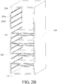
- a first embodiment shown in FIG. 2A provides cooling for the galley cart 100 by providing multiple individual refrigerant bricks 202 which are received in the interior cavity 112 of the housing 140.
- the refrigerant bricks 202 interengage selected support rails 146.
- the refrigerant bricks 202 may be fabricated from molded plastic or similar materials and contain refreezable liquid or chemical compositions such as Rubbermaid BLUE ICE® or salt water mixtures. Because the bricks include a refrigerant that can be frozen prior to use, dry ice is not used in the cart and no additional power source for the cart is needed. Further, as the bricks cool the surrounding volume, the bricks do not emit any gases or other materials.
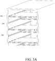
- the support rails 146 have depressions or slots 204 defined therein along either half the rail length or the whole rail length.
- the slots 204 are in a first half of a selected rail length, as shown for example on rail 206a
- the rail 206b above and/or below the selected rail has slots in the second half of the rail length, as shown for example on rail 206b.
- the embodiment shown employs relatively flat and thin refrigerant bricks 202.
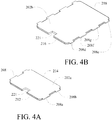
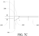
- the refrigerant bricks 202 each have tabs 208 horizontally extending from two opposing side edges 209a and 209b of the brick (seen in FIGs.
- FIG. 3B shows one brick removed to show the slots 204 with the bricks in an alternating configuration to be described in greater detail subsequently.
- the bricks shown in detail in FIGs. 4A and 4B can come in at least two different sizes; a standard size brick 202a and a long-haul size brick 202b.
- the length of a long-haul sized brick is substantially one half the internal length of the housing.
- the length of the standard size brick is approximately one third of the internal length of the housing.
- lengths of the bricks may be varied to accommodate various storage configurations and storage drawer sizes.
- the airlines can select which size(s) of bricks to insert in the cart based on flight conditions (i.e., duration). Relative size of the standard and long haul bricks is seen in FIG. 4C .
- Tabs 208 as a first mating moiety on the bricks 202 may have differing sizes to encode a proper orientation and position for the brick on the selected support rail.
- a standard haul brick 202a may have opposing tabs 208a having a first longitudinal dimension ("wide tabs") adjacent a first end 212 of the brick and opposing tabs 208b having a second longitudinal dimension narrower than the first longitudinal dimension ("narrow tabs") adjacent a second end 214 of the brick.
- a long haul brick 202b as shown in FIG. 4B may have opposing narrow tabs 208d adjacent a first end 216 and opposing narrow tabs 208e adjacent a second end 218 with two sets of opposing wide tabs 208f and 208g between the narrow tabs.
- the first longitudinal dimension of the wide tabs may be approximately 2 3 ⁇ 4 inches while the second longitudinal dimension of the narrow tabs may be approximately 1 1 ⁇ 2 inches.
- the slots 204 in the support rail 146 may be narrow slots 204a corresponding to the second longitudinal dimension for tabs on the bricks or wide slots 204b corresponding to the first longitudinal dimension of the tabs on the bricks.
- a narrow slot followed by two wide slots followed by a narrow slot provides an encoded mating engagement of a long haul brick placing the first end 216 immediately adjacent the end aperture 114a and the second end 218 adjacent a center plane 220 of the cart. Mating engagement of a standard brick centers the brick between the aperture and the center plane of the cart.
- the small tabs of the standard brick will be received in either wide slot but the wide tab can only be received in one of the wide slots thereby providing the centering position with either of two mirrored orientations of the standard brick. While a single orientation for each of the standard and long haul bricks has been shown, alternative encoding patterns may be employed to specifically orient bricks on various support rails within the cart. Additionally, a finger slot 221 may be employed to assist in handling of the refrigerant bricks for insertion and removal and to provide a visual reference for the orientation of the brick to assure alignment of the encoded mating moieties.
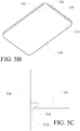
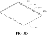
- FIGs. 5A - 5D An alternative embodiment for the support rails and refrigerant bricks is shown in FIGs. 5A - 5D wherein the support rails receiving the refrigerant bricks are divided into segments having various lengths; wide segments 222a and 222b and narrow segments 222c, 222d, 222e, 222f,222g and 222h (as shown in FIG. 5A ) as the second mating moiety for the encoded coupling.
- the refrigerant bricks such as a standard brick 224 shown in FIG. 5B , incorporate indentations 226 as the first mating moiety of the encoded coupling to receive the support rail segments. This geometry allows the volume of the refrigerant bricks to extend to the walls 228 of the housing (shown in FIG.
- FIG. 5A as partial views of the side portions 141 and 142 of FIGs. 1A and 1B ).
- intermediate portions 230 and end portions 232 provide significant additional volume for refrigerant between the indentations and outside the indentations respectively.
- the encoding of matching segments on the rails and indentations on the refrigerant bricks allows specific positional definition for the refrigerant bricks.
- a standard brick 224 having two short indentations 226 may only be received on corresponding rail short elements 222c and 222d or 222f and 222g.
- a long haul brick 225 as shown in FIG.
- 5D employs a wide indentation 234 and three short indentations 236a, 223b and 236c.
- a central mounting within the housing of either standard or long haul brick may be accomplished since the narrow segment 222d or 222f may be received in the wide indentation 234 when mounted from opposite apertures of the cart.
- the bricks can be positioned in a full cart configuration as shown in FIG. 6A , with refrigerant bricks 202 staggered on alternating rails 146 inserted from opposite apertures 114a and 114b.
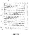
- a vertical half cart configuration as shown in FIG. 6B employs bricks 202 mounted from only one aperture in the cart.
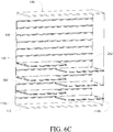
- a horizontal half cart configuration as show in FIG. 6C allows cooling of selected portions of the cart cavity 112.
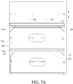
- the bricks 202 have a thickness 210 that is substantially equal to a height of the support rails 146 as shown in FIG. 7A so the bricks do not occupy cavity volume that could otherwise be occupied by supplies.
- the thickness 209 of the tabs 208 corresponds to the depth of the slots 204 in the support rails 146 thereby creating a flat surface with the upper surface 211 of the support rail. Clearance is thereby provided for storage drawers 240 to be received between the refrigerant bricks.
- the storage drawers employ a central support channel 242 to receive the support rail 146a between the support rails 146b and 146c holding the refrigerant bricks.
- the central support channel is not required and the storage draws are support on the support rail/refrigerant brick surface.
- Serving trays 244 may also be supported either by the rails or by the refrigerant bricks.
- FIG. 7B storage drawers are inserted from opposite apertures in the cart and abut the alternating refrigerant bricks thereby providing baffling for limiting the dispersion of convection cooling between the bricks.
- thermocouples TC01 to TC12 As shown in FIG. 8A for a configuration of thermocouples TC01 to TC12 shown in FIG. 8B , the temperatures provided by the refrigerant bricks in a full cart configuration, as described above with respect to FIG. 6A , are maintained at a substantially evenly distributed common temperature with a variation of only about 12 degrees F between top and bottom and maintaining the temperature over a 12 hour period (2AM to 2PM) with a variance of only about 2 degrees.
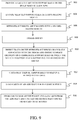
- a galley cart is provided with support rails on the inner sides of a housing, step 902.
- Selected support rails are encoded as a first mating moiety, step 904.
- Refrigerant bricks are encoded with a second mating moiety, step 906, are frozen, step 908, and are received on the selected support rails in a selected configuration, step 910.
- Trays may be inserted on the refrigerant bricks or on rails associated with the bricks and storage drawers are inserted on intermediate support rails between the selected support rails supporting the refrigerant bricks, step 912.
- Carts may then be temporarily stored in a refrigerated area, step 914.
- Carts are then loaded on an aircraft for in-flight service, step 916. Upon conclusion of the flight, carts are unloaded from the aircraft and the refrigerant bricks are unloaded to be reused, step 918.
Landscapes
- Engineering & Computer Science (AREA)
- Physics & Mathematics (AREA)
- Thermal Sciences (AREA)
- Chemical & Material Sciences (AREA)
- Combustion & Propulsion (AREA)
- Mechanical Engineering (AREA)
- General Engineering & Computer Science (AREA)
- Aviation & Aerospace Engineering (AREA)
- Handcart (AREA)
Claims (13)
- Bordküchenwagen (100) aufweisend:ein Gehäuse (102), das einen Hohlraum (112) darin definiert;mindestens eine horizontale Stützschiene (146), die sich von dem Gehäuse innerhalb des Hohlraums erstreckt;mehrere Schlitze (204) in der mindestens einen Stützschiene (146) und einstückig mit der Stützschiene ausgebildet; und mindestens einen Kältemittelblock (202) mit zusammenpassenden Laschen (208), die sich von gegenüberliegenden Seiten (209a, 209b) des mindestens einen Kältemittelblocks (202) erstrecken, der in den Schlitzen (204) in der mindestens einen Stützschiene (146) aufgenommen ist, um den Kältemittelblock innerhalb des Hohlraums zu koppeln.
- Bordküchenwagen (100) nach Anspruch 1, wobei die Schlitze breite Schlitze (204b) und schmale Schlitze (204a) aufweisen, die in einem Muster angeordnet sind, und Laschen breite Laschen (208f,g) und schmale Laschen (208d,e) aufweisen, die in einem zusammenpassenden Muster angeordnet sind, um in den zugehörigen breiten Schlitzen und schmalen Schlitzen aufgenommen zu werden.
- Bordküchenwagen (100) aufweisend:ein Gehäuse (102), das einen Hohlraum (112) darin definiert;mindestens eine horizontale Stützschiene (146), die sich von dem Gehäuse innerhalb des Hohlraums erstreckt;mehrere Stützschienensegmente (222), die einstückig mit der Stützschiene ausgebildet sind; undmindestens einen Kältemittelblock (202) mit zusammenpassenden Vertiefungen (226) in gegenüberliegenden Kanten des mindestens einen Kältemittelblocks (202) zum Aufnehmen der Segmente (222), um den Kältemittelblock innerhalb des Hohlraums zu koppeln.
- Bordküchenwagen (100) nach Anspruch 3, wobei die Segmente breite Segmente (222a,b) und schmale Segmente (222c-h) aufweisen, die in einem Muster angeordnet sind, und die Vertiefungen breite Vertiefungen (234) und schmale Vertiefungen (226, 236a, 223b, 236c) aufweisen, die in einem zusammenpassenden Muster angeordnet sind, um die zugehörigen breiten Segmente und schmalen Segmente aufzunehmen.
- Bordküchenwagen (100) nach einem der vorhergehenden Ansprüche, wobei eine obere Fläche des mindestens einen Kühlmittelblocks (202) im Wesentlichen komplanar mit einer oberen Fläche der mindestens einen Stützschiene (146) ist, wenn der Kühlmittelblock mit der mindestens einen Stützschiene gekoppelt ist.
- Bordküchenwagen (100) nach einem der vorhergehenden Ansprüche, wobei der mindestens eine Kühlmittelblock (202) eine starre Schale und ein Kühlmittel innerhalb der Schale aufweist.
- Bordküchenwagen (100) nach einem der vorhergehenden Ansprüche, wobei der mindestens eine Kühlmittelblock (202) ein Block (202a) erster Größe ist, der für eine Standardverwendung definiert ist, oder ein Block (202b) zweiter Größe ist, der für eine Langstreckenverwendung definiert ist.
- Bordküchenwagen (100) nach einem der vorhergehenden Ansprüche, wobei die Schlitze (204) oder Segmente (222) entlang etwa der Hälfte einer Länge der mindestens einen Stützschiene (146) definiert sind.
- Bordküchenwagen (100) nach einem der vorhergehenden Ansprüche, wobei die mindestens eine Stützschiene (146) mehrere Stützschienen aufweist und die Schlitze oder Segmente auf benachbarten Stützschienen in den mehreren Stützschienen gegeneinander versetzt sind.
- Bordküchenwagen (100) nach einem der vorhergehenden Ansprüche, wobei die Schlitze (204) oder Segmente (222) entlang einer gesamten Länge der mindestens einen Stützschiene (146) definiert sind.
- Verfahren zum Kühlen eines Bordküchenwagens (100), wobei das Verfahren Folgendes aufweist:Bereitstellen von Schlitzen (204) oder Segmenten (222) an ausgewählten horizontalen Stützschienen (146) an inneren Wänden eines Gehäuses (102) des Bordküchenwagens;Bereitstellen von Kältemittelblöcken (202) mit jeweiligen zusammenpassenden Laschen (208), die sich von gegenüberliegenden Seiten des Kältemittelblocks oder der Vertiefungen (226) in gegenüberliegende Kanten des Kältemittelblocks erstrecken;Einfrieren der Kältemittelblöcke vor der Verwendung in dem Bordküchenwagen undAufnehmen der gefrorenen Kühlmittelblöcke auf den ausgewählten Stützschienen in die Schlitze (204) oder die Segmente (222), die in den gefrorenen Kühlmittelblöcken in einer ausgewählten Konfiguration aufgenommen sind.
- Verfahren nach Anspruch 11, ferner aufweisend:
Einführen von Aufbewahrungsschubladen (240) zwischen die Kühlmittelblöcke (202). - Verfahren nach Anspruch 12, wobei das Einführen der Aufbewahrungsschublade (240) Folgendes aufweist:
Einführen der Aufbewahrungsschubladen auf dazwischenliegende Stützschienen (146) zwischen den ausgewählten Stützschienen (146), welche die Kältemittelblöcke (202) stützen.
Applications Claiming Priority (1)
| Application Number | Priority Date | Filing Date | Title |
|---|---|---|---|
| US13/890,416 US9193461B2 (en) | 2013-05-09 | 2013-05-09 | Insulated galley cart and method of using frozen refrigerant bricks to maximize storage volume and equalize temperature distribution |
Publications (2)
| Publication Number | Publication Date |
|---|---|
| EP2808254A1 EP2808254A1 (de) | 2014-12-03 |
| EP2808254B1 true EP2808254B1 (de) | 2019-05-08 |
Family
ID=50687292
Family Applications (1)
| Application Number | Title | Priority Date | Filing Date |
|---|---|---|---|
| EP14167492.9A Active EP2808254B1 (de) | 2013-05-09 | 2014-05-08 | Isoliertes Bordküchenfach und Verfahren zur Verwendung gefrorener Kältemittelblocks zur Maximierung des Speichervolumens und zum Ausgleichen der Temperaturverteilung |
Country Status (5)
| Country | Link |
|---|---|
| US (1) | US9193461B2 (de) |
| EP (1) | EP2808254B1 (de) |
| JP (1) | JP6220727B2 (de) |
| BR (1) | BR102014011166B1 (de) |
| CA (1) | CA2847164C (de) |
Families Citing this family (8)
| Publication number | Priority date | Publication date | Assignee | Title |
|---|---|---|---|---|
| US20160290023A1 (en) * | 2015-04-01 | 2016-10-06 | Norduyn Inc. | Galley cart locking mechanism and method of use thereof |
| KR101617639B1 (ko) * | 2015-12-24 | 2016-05-03 | 주식회사 에프엠에스코리아 | 저온물품 저장용 이동식 컨테이너 |
| CN105942714A (zh) * | 2016-06-07 | 2016-09-21 | 国网浙江永康市供电公司 | 一种多功能餐车及其控制方法 |
| US10053355B2 (en) | 2016-06-20 | 2018-08-21 | The Boeing Company | Adaptable insulated galley cart carbonated beverage delivery system |
| US20180215467A1 (en) * | 2017-01-30 | 2018-08-02 | The Boeing Company | Overhead Bin with Two Substantially Rigid Shelves |
| IT201800001313A1 (it) * | 2018-01-18 | 2019-07-18 | La Tavola S R L | Elemento funzionale di presentazione di cibo. |
| US20200339262A1 (en) * | 2019-04-29 | 2020-10-29 | B/E Aerospace, Inc. | Galley Cart Wheel Track |
| EP4030964B1 (de) * | 2019-09-16 | 2025-01-15 | Phaslo Global Innovation Pty Ltd | Temperierte schale |
Family Cites Families (24)
| Publication number | Priority date | Publication date | Assignee | Title |
|---|---|---|---|---|
| US4346756A (en) | 1980-08-20 | 1982-08-31 | Uop Inc. | Apparatus for selectively heating an individual food item in a refrigerated environment |
| JPS58139954U (ja) * | 1982-03-15 | 1983-09-20 | 松下電工株式会社 | 側板と棚板との結合構造 |
| DE4308144C1 (de) | 1993-03-15 | 1994-10-27 | Deutsche Aerospace Airbus | Servierwagen an Bord eines Flugzeuges |
| US5524980A (en) * | 1993-07-15 | 1996-06-11 | Rx For Organization | Medicine cabinet organizing insert |
| JP2592303Y2 (ja) * | 1993-07-29 | 1999-03-17 | 南部化成株式会社 | 棚板の固定構造 |
| US5419152A (en) * | 1993-12-13 | 1995-05-30 | In Vitro Technologies, Inc. | Apparatus for packaging temperature sensitive materials for transportation |
| JPH07236527A (ja) * | 1994-02-25 | 1995-09-12 | Matsushita Electric Works Ltd | 棚板取付装置 |
| US6230515B1 (en) * | 1997-11-28 | 2001-05-15 | Jon P. Wiesman | Container arrangement and method for transporting equine semen |
| JP3248871B2 (ja) * | 1998-02-09 | 2002-01-21 | 株式会社イノアックコーポレーション | 蓄冷剤容器並びに保冷容器及び蓄冷剤容器の組付構造 |
| AU6118399A (en) * | 1998-10-12 | 2000-05-01 | Tineke Charlotte Kouwenberg | Cooled drawer for aircraft food trolley |
| US6135273A (en) * | 1999-03-31 | 2000-10-24 | Cuen; Joseph Anthony | Thermal bag |
| US6540249B2 (en) * | 1999-05-21 | 2003-04-01 | Icb, Llc | Collapsible cart with shelf |
| DE20014683U1 (de) | 2000-08-24 | 2001-01-04 | Hupfer Metallwerke GmbH & Co., 48653 Coesfeld | Speisentransportwagen mit Trennsäule |
| US6651970B2 (en) * | 2001-11-19 | 2003-11-25 | Robert Scott | Multi-functional cutting board |
| US7216773B2 (en) * | 2003-10-31 | 2007-05-15 | Metal Fabricating Corporation | Quick assembly storage cabinet |
| US7444830B2 (en) | 2004-03-08 | 2008-11-04 | The Boeing Company | Aircraft galley carts and other insulated food storage units, and methods for their use |
| US7909806B2 (en) * | 2004-09-23 | 2011-03-22 | Anthrogenesis Corporation | Cord blood and placenta collection kit |
| US7147626B2 (en) * | 2004-09-23 | 2006-12-12 | Celgene Corporation | Cord blood and placenta collection kit |
| JP4648244B2 (ja) * | 2006-05-31 | 2011-03-09 | コイズミファニテック株式会社 | 棚受け部材 |
| US7731316B2 (en) * | 2006-06-09 | 2010-06-08 | Maytag Corporation | Universal shelf module for a refrigerator |
| GB2459392B (en) * | 2009-05-29 | 2010-04-07 | Softbox Systems Ltd | Transport container |
| US8474274B2 (en) * | 2010-05-11 | 2013-07-02 | The Boeing Company | Refrigerated container |
| US20120085745A1 (en) | 2010-10-08 | 2012-04-12 | Cambro Manufacturing Company | Dual Climate Cart and Tray for Accommodating Comestible Items and a Method of Operating the Same |
| JP5801070B2 (ja) * | 2011-03-16 | 2015-10-28 | 大和ハウス工業株式会社 | 収納空間構造 |
-
2013
- 2013-05-09 US US13/890,416 patent/US9193461B2/en active Active
-
2014
- 2014-03-19 CA CA2847164A patent/CA2847164C/en active Active
- 2014-05-02 JP JP2014094989A patent/JP6220727B2/ja active Active
- 2014-05-08 EP EP14167492.9A patent/EP2808254B1/de active Active
- 2014-05-08 BR BR102014011166-2A patent/BR102014011166B1/pt active IP Right Grant
Non-Patent Citations (1)
| Title |
|---|
| None * |
Also Published As
| Publication number | Publication date |
|---|---|
| BR102014011166A2 (pt) | 2015-07-14 |
| JP2014236960A (ja) | 2014-12-18 |
| JP6220727B2 (ja) | 2017-10-25 |
| US9193461B2 (en) | 2015-11-24 |
| US20140331695A1 (en) | 2014-11-13 |
| CA2847164A1 (en) | 2014-11-09 |
| BR102014011166B1 (pt) | 2021-10-26 |
| CA2847164C (en) | 2016-07-26 |
| EP2808254A1 (de) | 2014-12-03 |
Similar Documents
| Publication | Publication Date | Title |
|---|---|---|
| CA2847164C (en) | Insulated galley cart and method of using frozen refrigerant bricks to maximize storage volume and equalize temperature distribution | |
| EP2799337B1 (de) | Vertikal montiertes Trockeneiskühlfach für einen Servicewagen zur Temperaturverlaufsminderung | |
| EP2807957A1 (de) | Doppelfunktions-Nahrungsmittelschalen-Trägerrohre für einen Bordküchenwagen | |
| EP3095699B1 (de) | Bordküchenwagen und bordküchensystem eines flugzeugs | |
| US9802703B2 (en) | Galley compartment for a galley system of an aircraft | |
| US20130048264A1 (en) | Aircraft galley liquid cooling system | |
| US20150289643A1 (en) | Galley cooling system and method of operating a galley cooling system | |
| AU2016228277B2 (en) | Galley system of an aircraft | |
| EP3010803B1 (de) | Positionier- und einbausystem für vorrichtungseinsätze für flugzeugbordküchen | |
| US4399667A (en) | Apparatus for chilling a plurality of food trays | |
| US11730263B2 (en) | System for storing and delivering food trays | |
| US20180134389A1 (en) | Chiller galley cart, galley, and method for cooling | |
| CN104603562A (zh) | 多入口飞机厨房制冷机 | |
| US9523506B2 (en) | Double deep, single width ovens for use in aircraft galleys | |
| US20130255662A1 (en) | Oven Having Slidable Drawer Mechanism | |
| CN105939931A (zh) | 厨房容器以及用于冷却厨房容器内部的冷却件 | |
| WO2011116171A2 (en) | Meal trays | |
| EP4289737A1 (de) | Hochleistungs-mikro-chiller-einheit | |
| US20210278119A1 (en) | Replaceable Thermal Heating or Cooling (RTHC) Device for Aircraft Meal Boxes and Compartments | |
| JP6369975B2 (ja) | 収納装置 | |
| JP2014040937A (ja) | 冷温蔵装置 | |
| EP4030964B1 (de) | Temperierte schale | |
| CN105307936B (zh) | 具有器具嵌件的飞行器厨房 | |
| JP4725289B2 (ja) | 配膳車 | |
| CA2307609A1 (en) | Stackable container |
Legal Events
| Date | Code | Title | Description |
|---|---|---|---|
| PUAI | Public reference made under article 153(3) epc to a published international application that has entered the european phase |
Free format text: ORIGINAL CODE: 0009012 |
|
| 17P | Request for examination filed |
Effective date: 20140508 |
|
| AK | Designated contracting states |
Kind code of ref document: A1 Designated state(s): AL AT BE BG CH CY CZ DE DK EE ES FI FR GB GR HR HU IE IS IT LI LT LU LV MC MK MT NL NO PL PT RO RS SE SI SK SM TR |
|
| AX | Request for extension of the european patent |
Extension state: BA ME |
|
| GRAP | Despatch of communication of intention to grant a patent |
Free format text: ORIGINAL CODE: EPIDOSNIGR1 |
|
| STAA | Information on the status of an ep patent application or granted ep patent |
Free format text: STATUS: GRANT OF PATENT IS INTENDED |
|
| INTG | Intention to grant announced |
Effective date: 20180710 |
|
| GRAJ | Information related to disapproval of communication of intention to grant by the applicant or resumption of examination proceedings by the epo deleted |
Free format text: ORIGINAL CODE: EPIDOSDIGR1 |
|
| STAA | Information on the status of an ep patent application or granted ep patent |
Free format text: STATUS: REQUEST FOR EXAMINATION WAS MADE |
|
| GRAJ | Information related to disapproval of communication of intention to grant by the applicant or resumption of examination proceedings by the epo deleted |
Free format text: ORIGINAL CODE: EPIDOSDIGR1 |
|
| STAA | Information on the status of an ep patent application or granted ep patent |
Free format text: STATUS: GRANT OF PATENT IS INTENDED |
|
| GRAP | Despatch of communication of intention to grant a patent |
Free format text: ORIGINAL CODE: EPIDOSNIGR1 |
|
| INTC | Intention to grant announced (deleted) | ||
| INTG | Intention to grant announced |
Effective date: 20181205 |
|
| GRAS | Grant fee paid |
Free format text: ORIGINAL CODE: EPIDOSNIGR3 |
|
| GRAA | (expected) grant |
Free format text: ORIGINAL CODE: 0009210 |
|
| STAA | Information on the status of an ep patent application or granted ep patent |
Free format text: STATUS: THE PATENT HAS BEEN GRANTED |
|
| AK | Designated contracting states |
Kind code of ref document: B1 Designated state(s): AL AT BE BG CH CY CZ DE DK EE ES FI FR GB GR HR HU IE IS IT LI LT LU LV MC MK MT NL NO PL PT RO RS SE SI SK SM TR |
|
| REG | Reference to a national code |
Ref country code: GB Ref legal event code: FG4D |
|
| REG | Reference to a national code |
Ref country code: CH Ref legal event code: EP Ref country code: AT Ref legal event code: REF Ref document number: 1129753 Country of ref document: AT Kind code of ref document: T Effective date: 20190515 |
|
| REG | Reference to a national code |
Ref country code: DE Ref legal event code: R096 Ref document number: 602014046136 Country of ref document: DE |
|
| REG | Reference to a national code |
Ref country code: IE Ref legal event code: FG4D |
|
| REG | Reference to a national code |
Ref country code: NL Ref legal event code: MP Effective date: 20190508 |
|
| REG | Reference to a national code |
Ref country code: LT Ref legal event code: MG4D |
|
| PG25 | Lapsed in a contracting state [announced via postgrant information from national office to epo] |
Ref country code: ES Free format text: LAPSE BECAUSE OF FAILURE TO SUBMIT A TRANSLATION OF THE DESCRIPTION OR TO PAY THE FEE WITHIN THE PRESCRIBED TIME-LIMIT Effective date: 20190508 Ref country code: PT Free format text: LAPSE BECAUSE OF FAILURE TO SUBMIT A TRANSLATION OF THE DESCRIPTION OR TO PAY THE FEE WITHIN THE PRESCRIBED TIME-LIMIT Effective date: 20190908 Ref country code: AL Free format text: LAPSE BECAUSE OF FAILURE TO SUBMIT A TRANSLATION OF THE DESCRIPTION OR TO PAY THE FEE WITHIN THE PRESCRIBED TIME-LIMIT Effective date: 20190508 Ref country code: SE Free format text: LAPSE BECAUSE OF FAILURE TO SUBMIT A TRANSLATION OF THE DESCRIPTION OR TO PAY THE FEE WITHIN THE PRESCRIBED TIME-LIMIT Effective date: 20190508 Ref country code: HR Free format text: LAPSE BECAUSE OF FAILURE TO SUBMIT A TRANSLATION OF THE DESCRIPTION OR TO PAY THE FEE WITHIN THE PRESCRIBED TIME-LIMIT Effective date: 20190508 Ref country code: LT Free format text: LAPSE BECAUSE OF FAILURE TO SUBMIT A TRANSLATION OF THE DESCRIPTION OR TO PAY THE FEE WITHIN THE PRESCRIBED TIME-LIMIT Effective date: 20190508 Ref country code: NO Free format text: LAPSE BECAUSE OF FAILURE TO SUBMIT A TRANSLATION OF THE DESCRIPTION OR TO PAY THE FEE WITHIN THE PRESCRIBED TIME-LIMIT Effective date: 20190808 Ref country code: FI Free format text: LAPSE BECAUSE OF FAILURE TO SUBMIT A TRANSLATION OF THE DESCRIPTION OR TO PAY THE FEE WITHIN THE PRESCRIBED TIME-LIMIT Effective date: 20190508 Ref country code: NL Free format text: LAPSE BECAUSE OF FAILURE TO SUBMIT A TRANSLATION OF THE DESCRIPTION OR TO PAY THE FEE WITHIN THE PRESCRIBED TIME-LIMIT Effective date: 20190508 |
|
| PG25 | Lapsed in a contracting state [announced via postgrant information from national office to epo] |
Ref country code: RS Free format text: LAPSE BECAUSE OF FAILURE TO SUBMIT A TRANSLATION OF THE DESCRIPTION OR TO PAY THE FEE WITHIN THE PRESCRIBED TIME-LIMIT Effective date: 20190508 Ref country code: LV Free format text: LAPSE BECAUSE OF FAILURE TO SUBMIT A TRANSLATION OF THE DESCRIPTION OR TO PAY THE FEE WITHIN THE PRESCRIBED TIME-LIMIT Effective date: 20190508 Ref country code: BG Free format text: LAPSE BECAUSE OF FAILURE TO SUBMIT A TRANSLATION OF THE DESCRIPTION OR TO PAY THE FEE WITHIN THE PRESCRIBED TIME-LIMIT Effective date: 20190808 Ref country code: GR Free format text: LAPSE BECAUSE OF FAILURE TO SUBMIT A TRANSLATION OF THE DESCRIPTION OR TO PAY THE FEE WITHIN THE PRESCRIBED TIME-LIMIT Effective date: 20190809 |
|
| REG | Reference to a national code |
Ref country code: AT Ref legal event code: MK05 Ref document number: 1129753 Country of ref document: AT Kind code of ref document: T Effective date: 20190508 |
|
| REG | Reference to a national code |
Ref country code: CH Ref legal event code: PL |
|
| PG25 | Lapsed in a contracting state [announced via postgrant information from national office to epo] |
Ref country code: CH Free format text: LAPSE BECAUSE OF NON-PAYMENT OF DUE FEES Effective date: 20190531 Ref country code: LI Free format text: LAPSE BECAUSE OF NON-PAYMENT OF DUE FEES Effective date: 20190531 Ref country code: DK Free format text: LAPSE BECAUSE OF FAILURE TO SUBMIT A TRANSLATION OF THE DESCRIPTION OR TO PAY THE FEE WITHIN THE PRESCRIBED TIME-LIMIT Effective date: 20190508 Ref country code: SK Free format text: LAPSE BECAUSE OF FAILURE TO SUBMIT A TRANSLATION OF THE DESCRIPTION OR TO PAY THE FEE WITHIN THE PRESCRIBED TIME-LIMIT Effective date: 20190508 Ref country code: EE Free format text: LAPSE BECAUSE OF FAILURE TO SUBMIT A TRANSLATION OF THE DESCRIPTION OR TO PAY THE FEE WITHIN THE PRESCRIBED TIME-LIMIT Effective date: 20190508 Ref country code: CZ Free format text: LAPSE BECAUSE OF FAILURE TO SUBMIT A TRANSLATION OF THE DESCRIPTION OR TO PAY THE FEE WITHIN THE PRESCRIBED TIME-LIMIT Effective date: 20190508 Ref country code: AT Free format text: LAPSE BECAUSE OF FAILURE TO SUBMIT A TRANSLATION OF THE DESCRIPTION OR TO PAY THE FEE WITHIN THE PRESCRIBED TIME-LIMIT Effective date: 20190508 Ref country code: RO Free format text: LAPSE BECAUSE OF FAILURE TO SUBMIT A TRANSLATION OF THE DESCRIPTION OR TO PAY THE FEE WITHIN THE PRESCRIBED TIME-LIMIT Effective date: 20190508 |
|
| REG | Reference to a national code |
Ref country code: BE Ref legal event code: MM Effective date: 20190531 |
|
| REG | Reference to a national code |
Ref country code: DE Ref legal event code: R097 Ref document number: 602014046136 Country of ref document: DE |
|
| PG25 | Lapsed in a contracting state [announced via postgrant information from national office to epo] |
Ref country code: MC Free format text: LAPSE BECAUSE OF FAILURE TO SUBMIT A TRANSLATION OF THE DESCRIPTION OR TO PAY THE FEE WITHIN THE PRESCRIBED TIME-LIMIT Effective date: 20190508 Ref country code: LU Free format text: LAPSE BECAUSE OF NON-PAYMENT OF DUE FEES Effective date: 20190508 Ref country code: IT Free format text: LAPSE BECAUSE OF FAILURE TO SUBMIT A TRANSLATION OF THE DESCRIPTION OR TO PAY THE FEE WITHIN THE PRESCRIBED TIME-LIMIT Effective date: 20190508 Ref country code: SM Free format text: LAPSE BECAUSE OF FAILURE TO SUBMIT A TRANSLATION OF THE DESCRIPTION OR TO PAY THE FEE WITHIN THE PRESCRIBED TIME-LIMIT Effective date: 20190508 |
|
| PLBE | No opposition filed within time limit |
Free format text: ORIGINAL CODE: 0009261 |
|
| STAA | Information on the status of an ep patent application or granted ep patent |
Free format text: STATUS: NO OPPOSITION FILED WITHIN TIME LIMIT |
|
| PG25 | Lapsed in a contracting state [announced via postgrant information from national office to epo] |
Ref country code: TR Free format text: LAPSE BECAUSE OF FAILURE TO SUBMIT A TRANSLATION OF THE DESCRIPTION OR TO PAY THE FEE WITHIN THE PRESCRIBED TIME-LIMIT Effective date: 20190508 |
|
| 26N | No opposition filed |
Effective date: 20200211 |
|
| PG25 | Lapsed in a contracting state [announced via postgrant information from national office to epo] |
Ref country code: PL Free format text: LAPSE BECAUSE OF FAILURE TO SUBMIT A TRANSLATION OF THE DESCRIPTION OR TO PAY THE FEE WITHIN THE PRESCRIBED TIME-LIMIT Effective date: 20190508 Ref country code: IE Free format text: LAPSE BECAUSE OF NON-PAYMENT OF DUE FEES Effective date: 20190508 |
|
| PG25 | Lapsed in a contracting state [announced via postgrant information from national office to epo] |
Ref country code: BE Free format text: LAPSE BECAUSE OF NON-PAYMENT OF DUE FEES Effective date: 20190531 Ref country code: SI Free format text: LAPSE BECAUSE OF FAILURE TO SUBMIT A TRANSLATION OF THE DESCRIPTION OR TO PAY THE FEE WITHIN THE PRESCRIBED TIME-LIMIT Effective date: 20190508 |
|
| PG25 | Lapsed in a contracting state [announced via postgrant information from national office to epo] |
Ref country code: CY Free format text: LAPSE BECAUSE OF FAILURE TO SUBMIT A TRANSLATION OF THE DESCRIPTION OR TO PAY THE FEE WITHIN THE PRESCRIBED TIME-LIMIT Effective date: 20190508 |
|
| PG25 | Lapsed in a contracting state [announced via postgrant information from national office to epo] |
Ref country code: IS Free format text: LAPSE BECAUSE OF FAILURE TO SUBMIT A TRANSLATION OF THE DESCRIPTION OR TO PAY THE FEE WITHIN THE PRESCRIBED TIME-LIMIT Effective date: 20190908 |
|
| PG25 | Lapsed in a contracting state [announced via postgrant information from national office to epo] |
Ref country code: MT Free format text: LAPSE BECAUSE OF FAILURE TO SUBMIT A TRANSLATION OF THE DESCRIPTION OR TO PAY THE FEE WITHIN THE PRESCRIBED TIME-LIMIT Effective date: 20190508 Ref country code: HU Free format text: LAPSE BECAUSE OF FAILURE TO SUBMIT A TRANSLATION OF THE DESCRIPTION OR TO PAY THE FEE WITHIN THE PRESCRIBED TIME-LIMIT; INVALID AB INITIO Effective date: 20140508 |
|
| PG25 | Lapsed in a contracting state [announced via postgrant information from national office to epo] |
Ref country code: MK Free format text: LAPSE BECAUSE OF FAILURE TO SUBMIT A TRANSLATION OF THE DESCRIPTION OR TO PAY THE FEE WITHIN THE PRESCRIBED TIME-LIMIT Effective date: 20190508 |
|
| P01 | Opt-out of the competence of the unified patent court (upc) registered |
Effective date: 20230516 |
|
| PGFP | Annual fee paid to national office [announced via postgrant information from national office to epo] |
Ref country code: GB Payment date: 20260527 Year of fee payment: 13 |
|
| PGFP | Annual fee paid to national office [announced via postgrant information from national office to epo] |
Ref country code: DE Payment date: 20260528 Year of fee payment: 13 |
|
| PGFP | Annual fee paid to national office [announced via postgrant information from national office to epo] |
Ref country code: FR Payment date: 20260525 Year of fee payment: 13 |