EP2808169A2 - Dispositif adaptateur pour une imprimante - Google Patents
Dispositif adaptateur pour une imprimante Download PDFInfo
- Publication number
- EP2808169A2 EP2808169A2 EP14001839.1A EP14001839A EP2808169A2 EP 2808169 A2 EP2808169 A2 EP 2808169A2 EP 14001839 A EP14001839 A EP 14001839A EP 2808169 A2 EP2808169 A2 EP 2808169A2
- Authority
- EP
- European Patent Office
- Prior art keywords
- adapter device
- cartridge
- actuating
- printer
- adapter
- Prior art date
- Legal status (The legal status is an assumption and is not a legal conclusion. Google has not performed a legal analysis and makes no representation as to the accuracy of the status listed.)
- Granted
Links
Images


Classifications
-
- B—PERFORMING OPERATIONS; TRANSPORTING
- B41—PRINTING; LINING MACHINES; TYPEWRITERS; STAMPS
- B41J—TYPEWRITERS; SELECTIVE PRINTING MECHANISMS, i.e. MECHANISMS PRINTING OTHERWISE THAN FROM A FORME; CORRECTION OF TYPOGRAPHICAL ERRORS
- B41J2/00—Typewriters or selective printing mechanisms characterised by the printing or marking process for which they are designed
- B41J2/005—Typewriters or selective printing mechanisms characterised by the printing or marking process for which they are designed characterised by bringing liquid or particles selectively into contact with a printing material
- B41J2/01—Ink jet
- B41J2/17—Ink jet characterised by ink handling
- B41J2/175—Ink supply systems ; Circuit parts therefor
- B41J2/17503—Ink cartridges
- B41J2/17553—Outer structure
-
- B—PERFORMING OPERATIONS; TRANSPORTING
- B41—PRINTING; LINING MACHINES; TYPEWRITERS; STAMPS
- B41J—TYPEWRITERS; SELECTIVE PRINTING MECHANISMS, i.e. MECHANISMS PRINTING OTHERWISE THAN FROM A FORME; CORRECTION OF TYPOGRAPHICAL ERRORS
- B41J2/00—Typewriters or selective printing mechanisms characterised by the printing or marking process for which they are designed
- B41J2/005—Typewriters or selective printing mechanisms characterised by the printing or marking process for which they are designed characterised by bringing liquid or particles selectively into contact with a printing material
- B41J2/01—Ink jet
- B41J2/17—Ink jet characterised by ink handling
- B41J2/175—Ink supply systems ; Circuit parts therefor
- B41J2/17503—Ink cartridges
- B41J2/1752—Mounting within the printer
Definitions
- the present invention relates to an adapter device which is insertable into a cartridge receptacle of a printer and which is adapted to receive an ink cartridge (consumable cartridge for a printer).
- printers are known in a variety of different embodiments.
- ink cartridges or short cartridges are used in inkjet printers, these are so-called ink cartridges or short cartridges. These are used to operate in corresponding cartridge receptacles of the printer so that the ink outlet port of the ink cartridge is connected to an ink supply port of the printer.
- Ink cartridges have at least one ink chamber, which is formed of several walls mostly substantially box-shaped.
- the ink cartridge is inserted in the insertion direction - from back to front - in the cartridge receptacle of the printer, which is formed like a shaft and adapted to the shape of the ink cartridge.
- the Tintenauslassö réelle is connected to the front in the insertion direction front wall and when inserted to the arranged at the end of the shaft-like receptacle ink supply port of the printer.
- a special feature of this type of printer is that at the end of a cartridge receptacle each have a further opening or depression is formed, in which an actuating part of an electrical switch is arranged sunk. The actuating member is displaceable in the insertion direction and actuates the switch when it is pushed deep into said opening.
- the printer will only start operating when the electrical switches in all cartridge receptacles are pressed. For this purpose, each original cartridge of the Druckerherstllers a in the insertion direction forward on the Tintenauslassö réelle projecting projection, a so-called detection section. If a cartridge is inserted into the cartridge receptacle, the projection strikes the actuating part from behind and pushes it forward, so that the electrical switch is actuated. This releases the printer for operation.
- the projection on the cartridge should serve as a kind of key with which certain information regarding the type of cartridge should be transmitted to the printer.
- different types of cartridges may differ in the length of the protrusion, with a printer type activated only by a particular type of cartridge having a precisely corresponding protrusion.
- the present invention is based on the motivation to provide a solution by means of which the manufacturing and storage costs for cartridges that can be used in different printer types can be reduced.
- an adapter device which is insertable into a cartridge receptacle of a printer and which is adapted to receive an ink cartridge (consumable cartridge for a printer), which adapter device comprises a substantially flat base member extending in the insertion direction (from the back towards the front) and transversely thereto in the height direction (from bottom to top) and of which projects at least in its upper or lower region (longitudinal edge) a wall portion of the surface extension laterally (from left to right, thus transversely to the longitudinal extent and height extent) on a wall portion or on the base element, an actuating slide is mounted longitudinally displaceable in the insertion direction, which comprises at its front end in the insertion direction (forward) (power transmission) thrust finger and in its rear portion an actuating piece, wherein the thrust finger in the insertion direction forward over the Base element is also pushed out and the actuating piece has a rearwardly directed actuating surface which extends into the region between the wall part
- the adapter device can be inserted into the cartridge receptacle of a printer and fixed therein.
- the inventive construction of a flat base body which may be plate-shaped or frame-shaped, and in the upper and / or lower side laterally formed wall portions forms practically a laterally open "U" - or "L" profile.
- the main body extends along the lateral boundary of the cartridge receiving space in the printer, the wall parts protruding from the main body at least partially against the upper and / or lower inside of the cartridge receptacle of the printer.
- This design ensures that an inventive adapter similar to an original cartridge from the back to the front (in insertion) can be inserted into the cartridge holder of a printer and that subsequently inserted a cartridge as usual in the insertion direction forward in the cartridge receptacle with the adapter device therein can be.
- the main body of the adapter rests against the side of the cartridge, and the wall parts projecting laterally from the main body are located above or below the cartridge.
- the thrust finger of the actuating slide is in the insertion direction in front of the actuating part of the electrical switch, which is located in an opening or depression at the end of the cartridge receptacle.
- the cartridge pushes with its front against the actuating surface formed on the actuating piece of the actuating slide rear.
- the actuating slide is pushed forward, so that the push finger abuts against the actuating part of the switch and moves it into the switching position. This activates the switch on the printer.
- the actuating slide practically takes over the function of the projection attached to each cartridge in the individualized original cartridges, or in other words the actuating slide forms a mechanical extension of the actuating part of the switch, which now projects rearwardly into the cartridge receiving space of the printer.
- the main body may be plate-shaped or frame-shaped.
- the plate or the frame can be made relatively thin, so that the available in the cartridge receptacle cartridge receiving space is reduced only very slightly.
- a special feature of the invention is that the outer sides of the base body and / or the wall parts have fastening means which can be brought into engagement with holding devices in the cartridge receptacle of the printer.
- the adapter device is designed according to an original cartridge originally intended for a specific type of printer, For example, externally provided with fastening means such as guide means, rails, grooves, projections, locking means or the like, which correspond as in an original cartridge with corresponding counterparts in the cartridge receptacle.
- fastening means such as guide means, rails, grooves, projections, locking means or the like
- the base body or the wall parts have a movable locking element, which has a locking projection extending transversely to the insertion direction outwardly projecting locking projection, which is engageable with a corresponding locking recess in the cartridge receptacle in holding engagement, and the locking element in a release position inwardly is movable, so that the locking projection is releasable from the locking recess, wherein the movement of the locking element is blocked from the inside.
- the blocking of the locking element in the locking position can be effected in that the actuating slide is supported with a contact surface from the inside against the locking element when the actuating slide is pushed in the direction of insertion forward. In this position, the locking element can not be brought into the release position.
- the adapter can only be inserted into or removed from a cartridge receptacle when the locking element is brought into the release position. Conversely, it is not possible to insert or remove the adapter from a printer when the locking element is in the locking position. It follows that the locking element can only be moved when no cartridge cooperates with the adapter, i. Accordingly, the adapter can only be inserted or removed from a cartridge receptacle if it is handled individually and independently of a cartridge. It is not possible to first assemble the adapter and a cartridge and then insert them into the printer in combination. It is likewise not possible to remove an adapter located in a cartridge receptacle together with a cartridge inserted therein together from the cartridge receptacle.
- the adapter In practice, the adapter must first be inserted into the printer and fixed in the cartridge receptacle. Only then can a cartridge be used. Conveniently, the adapter remains in the printer when the cartridge is empty and is exchanged for a filled cartridge. The advantage is that as long as the adapter is in the printer, universally applicable cartridges can be used without individualized projection.
- a sliding guide is formed on the main body or a wall part, in which the actuating slide is displaceably mounted in the insertion direction.
- the sliding guide comprises, for example, one or more elongate openings, depressions and / or profiles (rails) which interact in a form-fitting manner with the actuating slide.
- the actuating slide is captively fixed to the sliding guide.
- the actuating slide may have undercut positive locking elements, which are locked under elastic deformation in corresponding counter-profiles on the base body, so that the actuating slide remains in normal use with the adapter.
- the base body with the wall parts and the actuating slide are designed as plastic injection molded parts.
- the adapter according to the invention can be made in an accurate fit and efficient.
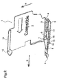
- FIG.1 and 2 show an adapter device according to the invention, also referred to as adapter for short, which is provided with the reference numeral 1.
- the adapter 1 comprises a flat, plate-shaped base element 2, which extends in the insertion direction E, which is indicated by an arrow, and transversely to the height direction H, which is also indicated by an arrow.
- a lower wall part 3 extends laterally out of the surface extension, that is, toward the viewer in the perspective shown.
- a longitudinal groove 4 running longitudinally in the insertion direction is formed on the side facing away from the observer.
- the wall part 3 has a width B such that it fits into a cartridge receptacle of a printer, not shown, like an original cartridge, in a form-fitting manner, ie. can be inserted with little side play in the insertion direction E.
- an actuating slide 5 is longitudinally slidably mounted in the insertion direction E, the in Fig.1 in withdrawn to the rear release position and in Fig.2 is shown in forward pushed locking position.
- the actuating slide 5 has a forwardly projecting thrust finger 6 and in its rear region an actuating piece 7 with a rearwardly directed actuating surface 8.
- the actuating slide 5 is held captive on the wall part 3 in a sliding guide formed by projections 9 and 10 and an opening in the direction of insertion E 11, which only in the in Fig.2 shown locking position is visible.
- a fastening means 12 in the form of a downwardly projecting projection 12. Due to the elasticity of the plastic material used, the projection 12 with the front wall part 3 in the release position ( Fig.1 ) to spring up, which is in Fig.1 with the little, up directed arrow is indicated. The spring travel is limited upwards by the underside of the actuating slide 7 and corresponds approximately to the downwardly projecting height of the projection 12. Thus, said projection 12 can be moved so far up that it is flush in the height direction with respect to the remaining underside of the wall part 3 sunk. In this position, the adapter 1 can be inserted into a cartridge receptacle until the projection 12 engages in a locking recess or opening in the underside of the cartridge receptacle, ie snaps back into its relaxed position.
- an upper wall portion 14 is mounted, which projects laterally on the viewer and in its front region has a fastening means 15 which is dimensioned so that it can be inserted with little lateral play in a cartridge receptacle.
- the major part of the fastening means 15 is designed as a ramp-shaped Entrast materials which rises in the insertion direction forward.
- the ramp shape means that the adapter 1 can usually be removed from a cartridge receptacle, not shown, opposite to the insertion direction, without having to actuate the conventional cartridge-side lever locking.
- the Entrast materials so abuts the end facing the Hebelverrastung that this is pushed by sliding along on the ramp-shaped Entrast components up in its Entrastposition and thus releases the adapter for removal.
- the adapter 1 has by the base member 2 with the upper and lower wall parts 14, 3 practically the shape of a viewer towards open U-profile.
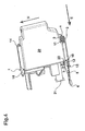
- This U-profile is in the direction of insertion front and rear also open, so that, if the adapter 1 is located in a cartridge receptacle of a printer, an ink cartridge 20 can be inserted or plugged in the direction of insertion from back to front in the profile. This is in Figure 3 shown.
- the ink cartridge 20 (cartridge) has on its front side an ink port 21 and a rearwardly offset forwardly facing front surface 22.
- the overall height of the cartridge 20 is sized to fit between the wall portions 3 and 14.
- the adapter 1 In the in Figure 4 illustrated position, the adapter 1 is in the locked position as in Fig.1 , This means, on the one hand, that the thrust finger 6 protrudes far forward and actuates a switch mounted inside the printer. On the other hand, the lower fastener, the projection 12, is blocked from moving upwardly by the operating slide 5, which engages the above-mentioned locking recess in the printer, so that the adapter 1, together with the cartridge 20 inserted, is locked in the cartridge receptacle of a printer. The adapter 1 can only be removed from the printer again when the cartridge 20 has been withdrawn in the opposite direction to the direction of insertion.
- the particular advantage of the invention is that a cartridge 20 can get along a substantially flat front surface 22 without special actuation projections or the like.
Landscapes
- Ink Jet (AREA)
Applications Claiming Priority (1)
| Application Number | Priority Date | Filing Date | Title |
|---|---|---|---|
| DE202013004920U DE202013004920U1 (de) | 2013-05-29 | 2013-05-29 | Adaptereinrichtung für einen Drucker |
Publications (3)
| Publication Number | Publication Date |
|---|---|
| EP2808169A2 true EP2808169A2 (fr) | 2014-12-03 |
| EP2808169A3 EP2808169A3 (fr) | 2016-07-13 |
| EP2808169B1 EP2808169B1 (fr) | 2017-03-29 |
Family
ID=48985379
Family Applications (1)
| Application Number | Title | Priority Date | Filing Date |
|---|---|---|---|
| EP14001839.1A Not-in-force EP2808169B1 (fr) | 2013-05-29 | 2014-05-27 | Dispositif adaptateur pour une imprimante |
Country Status (3)
| Country | Link |
|---|---|
| EP (1) | EP2808169B1 (fr) |
| DE (1) | DE202013004920U1 (fr) |
| ES (1) | ES2629495T3 (fr) |
Citations (1)
| Publication number | Priority date | Publication date | Assignee | Title |
|---|---|---|---|---|
| EP2397330B1 (fr) | 2010-06-17 | 2013-01-02 | Brother Kogyo Kabushiki Kaisha | Cartouche d'encre et appareil d'enregistrement |
Family Cites Families (2)
| Publication number | Priority date | Publication date | Assignee | Title |
|---|---|---|---|---|
| DE60315598T2 (de) * | 2003-04-25 | 2008-05-21 | Hewlett-Packard Development Co., L.P., Houston | Instandsetzungsvorrichtung für einen Drucker |
| ATE535379T1 (de) * | 2008-07-25 | 2011-12-15 | Brother Ind Ltd | Adapter für tintenpatrone |
-
2013
- 2013-05-29 DE DE202013004920U patent/DE202013004920U1/de not_active Expired - Lifetime
-
2014
- 2014-05-27 ES ES14001839.1T patent/ES2629495T3/es active Active
- 2014-05-27 EP EP14001839.1A patent/EP2808169B1/fr not_active Not-in-force
Patent Citations (1)
| Publication number | Priority date | Publication date | Assignee | Title |
|---|---|---|---|---|
| EP2397330B1 (fr) | 2010-06-17 | 2013-01-02 | Brother Kogyo Kabushiki Kaisha | Cartouche d'encre et appareil d'enregistrement |
Also Published As
| Publication number | Publication date |
|---|---|
| DE202013004920U1 (de) | 2013-07-16 |
| ES2629495T3 (es) | 2017-08-10 |
| EP2808169A3 (fr) | 2016-07-13 |
| EP2808169B1 (fr) | 2017-03-29 |
Similar Documents
| Publication | Publication Date | Title |
|---|---|---|
| EP2904982B1 (fr) | Appareil électrochirurgical doté d'un embout de douille, kit comprenant un outil de prélèvement et procéde de suppression d'un embout de douille | |
| DE69836420T2 (de) | Formmechanismus mit seitlicher wirkung und verfahren | |
| EP2196074B1 (fr) | Dispositif de verrouillage pour un boîtier destiné à loger un module enfichable | |
| DE202009001836U1 (de) | Elektromechanische Injektionsvorrichtung | |
| DE202010017857U1 (de) | Stempelkissen für einen selbstfärbenden Stempel | |
| EP1043128A1 (fr) | Couteau avec manche essentiellement creux pour retenir et guider un coulisseau | |
| EP1493129B1 (fr) | Tachygraphe muni d'un boitier parallelepipedique et d'un dispositif d'impression | |
| WO2021116129A1 (fr) | Composant de réception pour appareils électriques | |
| WO1996014682A1 (fr) | Boitier d'installation electrique a monter dans des murs, notamment dans des murs creux | |
| EP0606936B1 (fr) | Dispositif pour attacher d'une façon amovible un appareil électrique de service | |
| DE202017101346U1 (de) | Reihenklemme mit einem Aufnahmeschacht zum lösbaren Aufnehmen eines elektrischen und/oder elektronischen Bauelementes | |
| EP2281482B1 (fr) | Dispositifs d'éjection d'un guidage d'extraction et guidage d'extraction | |
| DE102013006183A1 (de) | Betätigungselement, Verbinder und Verfahren zum Entriegeln einer verriegelten Lanze | |
| EP2808169B1 (fr) | Dispositif adaptateur pour une imprimante | |
| DE2025504A1 (de) | Schiebetastenschalterpaket mit auswechselbarer Rast- und Sperrmechanik | |
| EP2156060B1 (fr) | Dispositif de fixation permettant d'assembler un profilé et un contre-profilé de façon libérable | |
| DE102013002729A1 (de) | Druckluft-Wartungsgerät zum Filtern von Druckluft sowie Verfahren zum Wechseln einer Filterpatrone | |
| EP3773074B1 (fr) | Systeme de tiroir comprenant un rail sur lequel differents types de tiroirs peuvent etre installes | |
| EP2997210B1 (fr) | Micromoteurs pour serrures d'automobile munies d'une butée axiale pour l'axe de moteur | |
| EP1835095B1 (fr) | Clé pour une serrure cylindrique | |
| EP1439067B1 (fr) | Procédé d'insertion d'un support dans un dispositif de maintien d'une cartouche et support correspondant | |
| DE102005030700B3 (de) | Vorrichtung zum Öffnen und Schließen einer Spritzgußform | |
| EP2988943A2 (fr) | Support de coussin pour tampon auto-encreur et dispositif et procédé de fabrication dudit support | |
| DE102016117669A1 (de) | Automatisch ausfahrbare Türspaltdichtung | |
| EP3760407A1 (fr) | Outil de moulage par injection destiné à la fabrication de pièces moulées par injection |
Legal Events
| Date | Code | Title | Description |
|---|---|---|---|
| PUAI | Public reference made under article 153(3) epc to a published international application that has entered the european phase |
Free format text: ORIGINAL CODE: 0009012 |
|
| 17P | Request for examination filed |
Effective date: 20140527 |
|
| AK | Designated contracting states |
Kind code of ref document: A2 Designated state(s): AL AT BE BG CH CY CZ DE DK EE ES FI FR GB GR HR HU IE IS IT LI LT LU LV MC MK MT NL NO PL PT RO RS SE SI SK SM TR |
|
| AX | Request for extension of the european patent |
Extension state: BA ME |
|
| PUAL | Search report despatched |
Free format text: ORIGINAL CODE: 0009013 |
|
| AK | Designated contracting states |
Kind code of ref document: A3 Designated state(s): AL AT BE BG CH CY CZ DE DK EE ES FI FR GB GR HR HU IE IS IT LI LT LU LV MC MK MT NL NO PL PT RO RS SE SI SK SM TR |
|
| AX | Request for extension of the european patent |
Extension state: BA ME |
|
| RIC1 | Information provided on ipc code assigned before grant |
Ipc: B41J 2/175 20060101AFI20160607BHEP |
|
| R17P | Request for examination filed (corrected) |
Effective date: 20160711 |
|
| RBV | Designated contracting states (corrected) |
Designated state(s): AL AT BE BG CH CY CZ DE DK EE ES FI FR GB GR HR HU IE IS IT LI LT LU LV MC MK MT NL NO PL PT RO RS SE SI SK SM TR |
|
| GRAP | Despatch of communication of intention to grant a patent |
Free format text: ORIGINAL CODE: EPIDOSNIGR1 |
|
| INTG | Intention to grant announced |
Effective date: 20161206 |
|
| GRAS | Grant fee paid |
Free format text: ORIGINAL CODE: EPIDOSNIGR3 |
|
| GRAA | (expected) grant |
Free format text: ORIGINAL CODE: 0009210 |
|
| AK | Designated contracting states |
Kind code of ref document: B1 Designated state(s): AL AT BE BG CH CY CZ DE DK EE ES FI FR GB GR HR HU IE IS IT LI LT LU LV MC MK MT NL NO PL PT RO RS SE SI SK SM TR |
|
| REG | Reference to a national code |
Ref country code: GB Ref legal event code: FG4D Free format text: NOT ENGLISH |
|
| REG | Reference to a national code |
Ref country code: CH Ref legal event code: EP |
|
| REG | Reference to a national code |
Ref country code: AT Ref legal event code: REF Ref document number: 879351 Country of ref document: AT Kind code of ref document: T Effective date: 20170415 |
|
| REG | Reference to a national code |
Ref country code: IE Ref legal event code: FG4D Free format text: LANGUAGE OF EP DOCUMENT: GERMAN |
|
| REG | Reference to a national code |
Ref country code: DE Ref legal event code: R096 Ref document number: 502014003155 Country of ref document: DE |
|
| REG | Reference to a national code |
Ref country code: FR Ref legal event code: PLFP Year of fee payment: 4 |
|
| REG | Reference to a national code |
Ref country code: CH Ref legal event code: NV Representative=s name: FIAMMENGHI-FIAMMENGHI, CH |
|
| REG | Reference to a national code |
Ref country code: NL Ref legal event code: FP |
|
| PG25 | Lapsed in a contracting state [announced via postgrant information from national office to epo] |
Ref country code: LT Free format text: LAPSE BECAUSE OF FAILURE TO SUBMIT A TRANSLATION OF THE DESCRIPTION OR TO PAY THE FEE WITHIN THE PRESCRIBED TIME-LIMIT Effective date: 20170329 Ref country code: HR Free format text: LAPSE BECAUSE OF FAILURE TO SUBMIT A TRANSLATION OF THE DESCRIPTION OR TO PAY THE FEE WITHIN THE PRESCRIBED TIME-LIMIT Effective date: 20170329 Ref country code: NO Free format text: LAPSE BECAUSE OF FAILURE TO SUBMIT A TRANSLATION OF THE DESCRIPTION OR TO PAY THE FEE WITHIN THE PRESCRIBED TIME-LIMIT Effective date: 20170629 Ref country code: FI Free format text: LAPSE BECAUSE OF FAILURE TO SUBMIT A TRANSLATION OF THE DESCRIPTION OR TO PAY THE FEE WITHIN THE PRESCRIBED TIME-LIMIT Effective date: 20170329 Ref country code: GR Free format text: LAPSE BECAUSE OF FAILURE TO SUBMIT A TRANSLATION OF THE DESCRIPTION OR TO PAY THE FEE WITHIN THE PRESCRIBED TIME-LIMIT Effective date: 20170630 |
|
| PGFP | Annual fee paid to national office [announced via postgrant information from national office to epo] |
Ref country code: CH Payment date: 20170519 Year of fee payment: 4 |
|
| REG | Reference to a national code |
Ref country code: ES Ref legal event code: FG2A Ref document number: 2629495 Country of ref document: ES Kind code of ref document: T3 Effective date: 20170810 |
|
| PG25 | Lapsed in a contracting state [announced via postgrant information from national office to epo] |
Ref country code: SE Free format text: LAPSE BECAUSE OF FAILURE TO SUBMIT A TRANSLATION OF THE DESCRIPTION OR TO PAY THE FEE WITHIN THE PRESCRIBED TIME-LIMIT Effective date: 20170329 Ref country code: LV Free format text: LAPSE BECAUSE OF FAILURE TO SUBMIT A TRANSLATION OF THE DESCRIPTION OR TO PAY THE FEE WITHIN THE PRESCRIBED TIME-LIMIT Effective date: 20170329 Ref country code: LU Free format text: LAPSE BECAUSE OF NON-PAYMENT OF DUE FEES Effective date: 20170531 Ref country code: RS Free format text: LAPSE BECAUSE OF FAILURE TO SUBMIT A TRANSLATION OF THE DESCRIPTION OR TO PAY THE FEE WITHIN THE PRESCRIBED TIME-LIMIT Effective date: 20170329 Ref country code: BG Free format text: LAPSE BECAUSE OF FAILURE TO SUBMIT A TRANSLATION OF THE DESCRIPTION OR TO PAY THE FEE WITHIN THE PRESCRIBED TIME-LIMIT Effective date: 20170629 |
|
| PG25 | Lapsed in a contracting state [announced via postgrant information from national office to epo] |
Ref country code: RO Free format text: LAPSE BECAUSE OF FAILURE TO SUBMIT A TRANSLATION OF THE DESCRIPTION OR TO PAY THE FEE WITHIN THE PRESCRIBED TIME-LIMIT Effective date: 20170329 Ref country code: SK Free format text: LAPSE BECAUSE OF FAILURE TO SUBMIT A TRANSLATION OF THE DESCRIPTION OR TO PAY THE FEE WITHIN THE PRESCRIBED TIME-LIMIT Effective date: 20170329 Ref country code: EE Free format text: LAPSE BECAUSE OF FAILURE TO SUBMIT A TRANSLATION OF THE DESCRIPTION OR TO PAY THE FEE WITHIN THE PRESCRIBED TIME-LIMIT Effective date: 20170329 Ref country code: CZ Free format text: LAPSE BECAUSE OF FAILURE TO SUBMIT A TRANSLATION OF THE DESCRIPTION OR TO PAY THE FEE WITHIN THE PRESCRIBED TIME-LIMIT Effective date: 20170329 |
|
| PG25 | Lapsed in a contracting state [announced via postgrant information from national office to epo] |
Ref country code: PL Free format text: LAPSE BECAUSE OF FAILURE TO SUBMIT A TRANSLATION OF THE DESCRIPTION OR TO PAY THE FEE WITHIN THE PRESCRIBED TIME-LIMIT Effective date: 20170329 Ref country code: IS Free format text: LAPSE BECAUSE OF FAILURE TO SUBMIT A TRANSLATION OF THE DESCRIPTION OR TO PAY THE FEE WITHIN THE PRESCRIBED TIME-LIMIT Effective date: 20170729 Ref country code: SM Free format text: LAPSE BECAUSE OF FAILURE TO SUBMIT A TRANSLATION OF THE DESCRIPTION OR TO PAY THE FEE WITHIN THE PRESCRIBED TIME-LIMIT Effective date: 20170329 Ref country code: PT Free format text: LAPSE BECAUSE OF FAILURE TO SUBMIT A TRANSLATION OF THE DESCRIPTION OR TO PAY THE FEE WITHIN THE PRESCRIBED TIME-LIMIT Effective date: 20170731 |
|
| REG | Reference to a national code |
Ref country code: DE Ref legal event code: R097 Ref document number: 502014003155 Country of ref document: DE |
|
| PG25 | Lapsed in a contracting state [announced via postgrant information from national office to epo] |
Ref country code: DK Free format text: LAPSE BECAUSE OF FAILURE TO SUBMIT A TRANSLATION OF THE DESCRIPTION OR TO PAY THE FEE WITHIN THE PRESCRIBED TIME-LIMIT Effective date: 20170329 Ref country code: MC Free format text: LAPSE BECAUSE OF FAILURE TO SUBMIT A TRANSLATION OF THE DESCRIPTION OR TO PAY THE FEE WITHIN THE PRESCRIBED TIME-LIMIT Effective date: 20170329 |
|
| PLBE | No opposition filed within time limit |
Free format text: ORIGINAL CODE: 0009261 |
|
| STAA | Information on the status of an ep patent application or granted ep patent |
Free format text: STATUS: NO OPPOSITION FILED WITHIN TIME LIMIT |
|
| REG | Reference to a national code |
Ref country code: IE Ref legal event code: MM4A |
|
| 26N | No opposition filed |
Effective date: 20180103 |
|
| PG25 | Lapsed in a contracting state [announced via postgrant information from national office to epo] |
Ref country code: LU Free format text: LAPSE BECAUSE OF NON-PAYMENT OF DUE FEES Effective date: 20170527 |
|
| REG | Reference to a national code |
Ref country code: BE Ref legal event code: MM Effective date: 20170531 |
|
| PG25 | Lapsed in a contracting state [announced via postgrant information from national office to epo] |
Ref country code: IE Free format text: LAPSE BECAUSE OF NON-PAYMENT OF DUE FEES Effective date: 20170527 |
|
| REG | Reference to a national code |
Ref country code: FR Ref legal event code: PLFP Year of fee payment: 5 |
|
| PG25 | Lapsed in a contracting state [announced via postgrant information from national office to epo] |
Ref country code: SI Free format text: LAPSE BECAUSE OF FAILURE TO SUBMIT A TRANSLATION OF THE DESCRIPTION OR TO PAY THE FEE WITHIN THE PRESCRIBED TIME-LIMIT Effective date: 20170329 |
|
| PG25 | Lapsed in a contracting state [announced via postgrant information from national office to epo] |
Ref country code: BE Free format text: LAPSE BECAUSE OF NON-PAYMENT OF DUE FEES Effective date: 20170531 |
|
| PG25 | Lapsed in a contracting state [announced via postgrant information from national office to epo] |
Ref country code: MT Free format text: LAPSE BECAUSE OF FAILURE TO SUBMIT A TRANSLATION OF THE DESCRIPTION OR TO PAY THE FEE WITHIN THE PRESCRIBED TIME-LIMIT Effective date: 20170329 |
|
| REG | Reference to a national code |
Ref country code: CH Ref legal event code: PL |
|
| PG25 | Lapsed in a contracting state [announced via postgrant information from national office to epo] |
Ref country code: LI Free format text: LAPSE BECAUSE OF NON-PAYMENT OF DUE FEES Effective date: 20180531 Ref country code: CH Free format text: LAPSE BECAUSE OF NON-PAYMENT OF DUE FEES Effective date: 20180531 |
|
| PG25 | Lapsed in a contracting state [announced via postgrant information from national office to epo] |
Ref country code: HU Free format text: LAPSE BECAUSE OF FAILURE TO SUBMIT A TRANSLATION OF THE DESCRIPTION OR TO PAY THE FEE WITHIN THE PRESCRIBED TIME-LIMIT; INVALID AB INITIO Effective date: 20140527 |
|
| PG25 | Lapsed in a contracting state [announced via postgrant information from national office to epo] |
Ref country code: CY Free format text: LAPSE BECAUSE OF FAILURE TO SUBMIT A TRANSLATION OF THE DESCRIPTION OR TO PAY THE FEE WITHIN THE PRESCRIBED TIME-LIMIT Effective date: 20170329 |
|
| PG25 | Lapsed in a contracting state [announced via postgrant information from national office to epo] |
Ref country code: MK Free format text: LAPSE BECAUSE OF FAILURE TO SUBMIT A TRANSLATION OF THE DESCRIPTION OR TO PAY THE FEE WITHIN THE PRESCRIBED TIME-LIMIT Effective date: 20170329 |
|
| PG25 | Lapsed in a contracting state [announced via postgrant information from national office to epo] |
Ref country code: TR Free format text: LAPSE BECAUSE OF FAILURE TO SUBMIT A TRANSLATION OF THE DESCRIPTION OR TO PAY THE FEE WITHIN THE PRESCRIBED TIME-LIMIT Effective date: 20170329 |
|
| PG25 | Lapsed in a contracting state [announced via postgrant information from national office to epo] |
Ref country code: AL Free format text: LAPSE BECAUSE OF FAILURE TO SUBMIT A TRANSLATION OF THE DESCRIPTION OR TO PAY THE FEE WITHIN THE PRESCRIBED TIME-LIMIT Effective date: 20170329 |
|
| REG | Reference to a national code |
Ref country code: AT Ref legal event code: MM01 Ref document number: 879351 Country of ref document: AT Kind code of ref document: T Effective date: 20190527 |
|
| PGFP | Annual fee paid to national office [announced via postgrant information from national office to epo] |
Ref country code: NL Payment date: 20200818 Year of fee payment: 7 |
|
| PGFP | Annual fee paid to national office [announced via postgrant information from national office to epo] |
Ref country code: GB Payment date: 20200826 Year of fee payment: 7 Ref country code: FR Payment date: 20200821 Year of fee payment: 7 Ref country code: ES Payment date: 20200825 Year of fee payment: 7 Ref country code: DE Payment date: 20200814 Year of fee payment: 7 |
|
| PG25 | Lapsed in a contracting state [announced via postgrant information from national office to epo] |
Ref country code: AT Free format text: LAPSE BECAUSE OF NON-PAYMENT OF DUE FEES Effective date: 20190527 |
|
| PGFP | Annual fee paid to national office [announced via postgrant information from national office to epo] |
Ref country code: IT Payment date: 20200826 Year of fee payment: 7 |
|
| REG | Reference to a national code |
Ref country code: DE Ref legal event code: R119 Ref document number: 502014003155 Country of ref document: DE |
|
| REG | Reference to a national code |
Ref country code: NL Ref legal event code: MM Effective date: 20210601 |
|
| GBPC | Gb: european patent ceased through non-payment of renewal fee |
Effective date: 20210527 |
|
| PG25 | Lapsed in a contracting state [announced via postgrant information from national office to epo] |
Ref country code: GB Free format text: LAPSE BECAUSE OF NON-PAYMENT OF DUE FEES Effective date: 20210527 Ref country code: DE Free format text: LAPSE BECAUSE OF NON-PAYMENT OF DUE FEES Effective date: 20211201 |
|
| PG25 | Lapsed in a contracting state [announced via postgrant information from national office to epo] |
Ref country code: NL Free format text: LAPSE BECAUSE OF NON-PAYMENT OF DUE FEES Effective date: 20210601 Ref country code: FR Free format text: LAPSE BECAUSE OF NON-PAYMENT OF DUE FEES Effective date: 20210531 |
|
| REG | Reference to a national code |
Ref country code: ES Ref legal event code: FD2A Effective date: 20220805 |
|
| PG25 | Lapsed in a contracting state [announced via postgrant information from national office to epo] |
Ref country code: ES Free format text: LAPSE BECAUSE OF NON-PAYMENT OF DUE FEES Effective date: 20210528 |
|
| PG25 | Lapsed in a contracting state [announced via postgrant information from national office to epo] |
Ref country code: IT Free format text: LAPSE BECAUSE OF NON-PAYMENT OF DUE FEES Effective date: 20200527 |
|
| PG25 | Lapsed in a contracting state [announced via postgrant information from national office to epo] |
Ref country code: IT Free format text: LAPSE BECAUSE OF NON-PAYMENT OF DUE FEES Effective date: 20210527 |