EP2808169A2 - Adapter device for a printer - Google Patents
Adapter device for a printer Download PDFInfo
- Publication number
- EP2808169A2 EP2808169A2 EP14001839.1A EP14001839A EP2808169A2 EP 2808169 A2 EP2808169 A2 EP 2808169A2 EP 14001839 A EP14001839 A EP 14001839A EP 2808169 A2 EP2808169 A2 EP 2808169A2
- Authority
- EP
- European Patent Office
- Prior art keywords
- adapter device
- cartridge
- actuating
- printer
- adapter
- Prior art date
- Legal status (The legal status is an assumption and is not a legal conclusion. Google has not performed a legal analysis and makes no representation as to the accuracy of the status listed.)
- Granted
Links
Images


Classifications
-
- B—PERFORMING OPERATIONS; TRANSPORTING
- B41—PRINTING; LINING MACHINES; TYPEWRITERS; STAMPS
- B41J—TYPEWRITERS; SELECTIVE PRINTING MECHANISMS, i.e. MECHANISMS PRINTING OTHERWISE THAN FROM A FORME; CORRECTION OF TYPOGRAPHICAL ERRORS
- B41J2/00—Typewriters or selective printing mechanisms characterised by the printing or marking process for which they are designed
- B41J2/005—Typewriters or selective printing mechanisms characterised by the printing or marking process for which they are designed characterised by bringing liquid or particles selectively into contact with a printing material
- B41J2/01—Ink jet
- B41J2/17—Ink jet characterised by ink handling
- B41J2/175—Ink supply systems ; Circuit parts therefor
- B41J2/17503—Ink cartridges
- B41J2/17553—Outer structure
-
- B—PERFORMING OPERATIONS; TRANSPORTING
- B41—PRINTING; LINING MACHINES; TYPEWRITERS; STAMPS
- B41J—TYPEWRITERS; SELECTIVE PRINTING MECHANISMS, i.e. MECHANISMS PRINTING OTHERWISE THAN FROM A FORME; CORRECTION OF TYPOGRAPHICAL ERRORS
- B41J2/00—Typewriters or selective printing mechanisms characterised by the printing or marking process for which they are designed
- B41J2/005—Typewriters or selective printing mechanisms characterised by the printing or marking process for which they are designed characterised by bringing liquid or particles selectively into contact with a printing material
- B41J2/01—Ink jet
- B41J2/17—Ink jet characterised by ink handling
- B41J2/175—Ink supply systems ; Circuit parts therefor
- B41J2/17503—Ink cartridges
- B41J2/1752—Mounting within the printer
Definitions
- the present invention relates to an adapter device which is insertable into a cartridge receptacle of a printer and which is adapted to receive an ink cartridge (consumable cartridge for a printer).
- printers are known in a variety of different embodiments.
- ink cartridges or short cartridges are used in inkjet printers, these are so-called ink cartridges or short cartridges. These are used to operate in corresponding cartridge receptacles of the printer so that the ink outlet port of the ink cartridge is connected to an ink supply port of the printer.
- Ink cartridges have at least one ink chamber, which is formed of several walls mostly substantially box-shaped.
- the ink cartridge is inserted in the insertion direction - from back to front - in the cartridge receptacle of the printer, which is formed like a shaft and adapted to the shape of the ink cartridge.
- the Tintenauslassö réelle is connected to the front in the insertion direction front wall and when inserted to the arranged at the end of the shaft-like receptacle ink supply port of the printer.
- a special feature of this type of printer is that at the end of a cartridge receptacle each have a further opening or depression is formed, in which an actuating part of an electrical switch is arranged sunk. The actuating member is displaceable in the insertion direction and actuates the switch when it is pushed deep into said opening.
- the printer will only start operating when the electrical switches in all cartridge receptacles are pressed. For this purpose, each original cartridge of the Druckerherstllers a in the insertion direction forward on the Tintenauslassö réelle projecting projection, a so-called detection section. If a cartridge is inserted into the cartridge receptacle, the projection strikes the actuating part from behind and pushes it forward, so that the electrical switch is actuated. This releases the printer for operation.
- the projection on the cartridge should serve as a kind of key with which certain information regarding the type of cartridge should be transmitted to the printer.
- different types of cartridges may differ in the length of the protrusion, with a printer type activated only by a particular type of cartridge having a precisely corresponding protrusion.
- the present invention is based on the motivation to provide a solution by means of which the manufacturing and storage costs for cartridges that can be used in different printer types can be reduced.
- an adapter device which is insertable into a cartridge receptacle of a printer and which is adapted to receive an ink cartridge (consumable cartridge for a printer), which adapter device comprises a substantially flat base member extending in the insertion direction (from the back towards the front) and transversely thereto in the height direction (from bottom to top) and of which projects at least in its upper or lower region (longitudinal edge) a wall portion of the surface extension laterally (from left to right, thus transversely to the longitudinal extent and height extent) on a wall portion or on the base element, an actuating slide is mounted longitudinally displaceable in the insertion direction, which comprises at its front end in the insertion direction (forward) (power transmission) thrust finger and in its rear portion an actuating piece, wherein the thrust finger in the insertion direction forward over the Base element is also pushed out and the actuating piece has a rearwardly directed actuating surface which extends into the region between the wall part
- the adapter device can be inserted into the cartridge receptacle of a printer and fixed therein.
- the inventive construction of a flat base body which may be plate-shaped or frame-shaped, and in the upper and / or lower side laterally formed wall portions forms practically a laterally open "U" - or "L" profile.
- the main body extends along the lateral boundary of the cartridge receiving space in the printer, the wall parts protruding from the main body at least partially against the upper and / or lower inside of the cartridge receptacle of the printer.
- This design ensures that an inventive adapter similar to an original cartridge from the back to the front (in insertion) can be inserted into the cartridge holder of a printer and that subsequently inserted a cartridge as usual in the insertion direction forward in the cartridge receptacle with the adapter device therein can be.
- the main body of the adapter rests against the side of the cartridge, and the wall parts projecting laterally from the main body are located above or below the cartridge.
- the thrust finger of the actuating slide is in the insertion direction in front of the actuating part of the electrical switch, which is located in an opening or depression at the end of the cartridge receptacle.
- the cartridge pushes with its front against the actuating surface formed on the actuating piece of the actuating slide rear.
- the actuating slide is pushed forward, so that the push finger abuts against the actuating part of the switch and moves it into the switching position. This activates the switch on the printer.
- the actuating slide practically takes over the function of the projection attached to each cartridge in the individualized original cartridges, or in other words the actuating slide forms a mechanical extension of the actuating part of the switch, which now projects rearwardly into the cartridge receiving space of the printer.
- the main body may be plate-shaped or frame-shaped.
- the plate or the frame can be made relatively thin, so that the available in the cartridge receptacle cartridge receiving space is reduced only very slightly.
- a special feature of the invention is that the outer sides of the base body and / or the wall parts have fastening means which can be brought into engagement with holding devices in the cartridge receptacle of the printer.
- the adapter device is designed according to an original cartridge originally intended for a specific type of printer, For example, externally provided with fastening means such as guide means, rails, grooves, projections, locking means or the like, which correspond as in an original cartridge with corresponding counterparts in the cartridge receptacle.
- fastening means such as guide means, rails, grooves, projections, locking means or the like
- the base body or the wall parts have a movable locking element, which has a locking projection extending transversely to the insertion direction outwardly projecting locking projection, which is engageable with a corresponding locking recess in the cartridge receptacle in holding engagement, and the locking element in a release position inwardly is movable, so that the locking projection is releasable from the locking recess, wherein the movement of the locking element is blocked from the inside.
- the blocking of the locking element in the locking position can be effected in that the actuating slide is supported with a contact surface from the inside against the locking element when the actuating slide is pushed in the direction of insertion forward. In this position, the locking element can not be brought into the release position.
- the adapter can only be inserted into or removed from a cartridge receptacle when the locking element is brought into the release position. Conversely, it is not possible to insert or remove the adapter from a printer when the locking element is in the locking position. It follows that the locking element can only be moved when no cartridge cooperates with the adapter, i. Accordingly, the adapter can only be inserted or removed from a cartridge receptacle if it is handled individually and independently of a cartridge. It is not possible to first assemble the adapter and a cartridge and then insert them into the printer in combination. It is likewise not possible to remove an adapter located in a cartridge receptacle together with a cartridge inserted therein together from the cartridge receptacle.
- the adapter In practice, the adapter must first be inserted into the printer and fixed in the cartridge receptacle. Only then can a cartridge be used. Conveniently, the adapter remains in the printer when the cartridge is empty and is exchanged for a filled cartridge. The advantage is that as long as the adapter is in the printer, universally applicable cartridges can be used without individualized projection.
- a sliding guide is formed on the main body or a wall part, in which the actuating slide is displaceably mounted in the insertion direction.
- the sliding guide comprises, for example, one or more elongate openings, depressions and / or profiles (rails) which interact in a form-fitting manner with the actuating slide.
- the actuating slide is captively fixed to the sliding guide.
- the actuating slide may have undercut positive locking elements, which are locked under elastic deformation in corresponding counter-profiles on the base body, so that the actuating slide remains in normal use with the adapter.
- the base body with the wall parts and the actuating slide are designed as plastic injection molded parts.
- the adapter according to the invention can be made in an accurate fit and efficient.
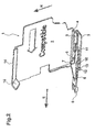
- FIG.1 and 2 show an adapter device according to the invention, also referred to as adapter for short, which is provided with the reference numeral 1.
- the adapter 1 comprises a flat, plate-shaped base element 2, which extends in the insertion direction E, which is indicated by an arrow, and transversely to the height direction H, which is also indicated by an arrow.
- a lower wall part 3 extends laterally out of the surface extension, that is, toward the viewer in the perspective shown.
- a longitudinal groove 4 running longitudinally in the insertion direction is formed on the side facing away from the observer.
- the wall part 3 has a width B such that it fits into a cartridge receptacle of a printer, not shown, like an original cartridge, in a form-fitting manner, ie. can be inserted with little side play in the insertion direction E.
- an actuating slide 5 is longitudinally slidably mounted in the insertion direction E, the in Fig.1 in withdrawn to the rear release position and in Fig.2 is shown in forward pushed locking position.
- the actuating slide 5 has a forwardly projecting thrust finger 6 and in its rear region an actuating piece 7 with a rearwardly directed actuating surface 8.
- the actuating slide 5 is held captive on the wall part 3 in a sliding guide formed by projections 9 and 10 and an opening in the direction of insertion E 11, which only in the in Fig.2 shown locking position is visible.
- a fastening means 12 in the form of a downwardly projecting projection 12. Due to the elasticity of the plastic material used, the projection 12 with the front wall part 3 in the release position ( Fig.1 ) to spring up, which is in Fig.1 with the little, up directed arrow is indicated. The spring travel is limited upwards by the underside of the actuating slide 7 and corresponds approximately to the downwardly projecting height of the projection 12. Thus, said projection 12 can be moved so far up that it is flush in the height direction with respect to the remaining underside of the wall part 3 sunk. In this position, the adapter 1 can be inserted into a cartridge receptacle until the projection 12 engages in a locking recess or opening in the underside of the cartridge receptacle, ie snaps back into its relaxed position.
- an upper wall portion 14 is mounted, which projects laterally on the viewer and in its front region has a fastening means 15 which is dimensioned so that it can be inserted with little lateral play in a cartridge receptacle.
- the major part of the fastening means 15 is designed as a ramp-shaped Entrast materials which rises in the insertion direction forward.
- the ramp shape means that the adapter 1 can usually be removed from a cartridge receptacle, not shown, opposite to the insertion direction, without having to actuate the conventional cartridge-side lever locking.
- the Entrast materials so abuts the end facing the Hebelverrastung that this is pushed by sliding along on the ramp-shaped Entrast components up in its Entrastposition and thus releases the adapter for removal.
- the adapter 1 has by the base member 2 with the upper and lower wall parts 14, 3 practically the shape of a viewer towards open U-profile.
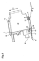
- This U-profile is in the direction of insertion front and rear also open, so that, if the adapter 1 is located in a cartridge receptacle of a printer, an ink cartridge 20 can be inserted or plugged in the direction of insertion from back to front in the profile. This is in Figure 3 shown.
- the ink cartridge 20 (cartridge) has on its front side an ink port 21 and a rearwardly offset forwardly facing front surface 22.
- the overall height of the cartridge 20 is sized to fit between the wall portions 3 and 14.
- the adapter 1 In the in Figure 4 illustrated position, the adapter 1 is in the locked position as in Fig.1 , This means, on the one hand, that the thrust finger 6 protrudes far forward and actuates a switch mounted inside the printer. On the other hand, the lower fastener, the projection 12, is blocked from moving upwardly by the operating slide 5, which engages the above-mentioned locking recess in the printer, so that the adapter 1, together with the cartridge 20 inserted, is locked in the cartridge receptacle of a printer. The adapter 1 can only be removed from the printer again when the cartridge 20 has been withdrawn in the opposite direction to the direction of insertion.
- the particular advantage of the invention is that a cartridge 20 can get along a substantially flat front surface 22 without special actuation projections or the like.
Landscapes
- Ink Jet (AREA)
Abstract
Eine Adaptereinrichtung (1), die in eine Kartuschenaufnahme eines Druckers einsetzbar ist und die zur Aufnahme einer Tintenkartusche (20) ausgebildet ist. Die Adaptereinrichtung (1) umfasst ein im wesentlichen flaches Grundelement (2), das sich in Einsetzrichtung (E) und quer dazu in Höhenrichtung (H) erstreckt und von dem zumindest in seinem oberen oder unteren Bereich ein Wandteil (3) aus der Flächenerstreckung seitlich vorsteht. An dem zumindest einen Wandteil (3) oder am Grundelement (2) ist ein Betätigungsschieber (5) in Einsetzrichtung (E) längsverschieblich gelagert, der an seinem in Einsetzrichtung vorderen Ende einen Schubfinger (6) und in seinem hinteren Bereich ein Betätigungsstück (7) umfasst. Dabei ist der Schubfinger (6) in Einsetzrichtung nach vorn über das Grundelement (2) hinaus hervorschiebbar und das Betätigungsstück (7) weist eine nach hinten gerichtete Betätigungsfläche (8) auf, die sich in den Bereich zwischen Wandteil (3) und Grundkörper (2) erstreckt.An adapter device (1) which can be inserted into a cartridge receptacle of a printer and which is designed to receive an ink cartridge (20). The adapter device (1) comprises a substantially flat base element (2) which extends in the direction of insertion (E) and transversely in the height direction (H) and of the at least in its upper or lower region, a wall part (3) from the surface extension laterally protrudes. On the at least one wall part (3) or on the base element (2) an actuating slide (5) is longitudinally displaceably mounted in the insertion direction (E), which at its front end in the insertion direction a thrust finger (6) and in its rear region an actuating piece (7) includes. In this case, the push finger (6) in the insertion direction forward on the base element (2) also pushed out and the actuating piece (7) has a rearwardly directed actuating surface (8) extending in the area between the wall part (3) and base body (2 ).
Description
Die vorliegende Erfindung betrifft eine Adaptereinrichtung, die in eine Kartuschenaufnahme eines Druckers einsetzbar ist und die zur Aufnahme einer Tintenkartusche (Verbrauchsmaterial-Kartusche für einen Drucker) ausgebildet ist.The present invention relates to an adapter device which is insertable into a cartridge receptacle of a printer and which is adapted to receive an ink cartridge (consumable cartridge for a printer).
Im Stand der Technik sind Drucker in einer Vielzahl von unterschiedlichen Ausführungsformen bekannt. Zur Versorgung mit Verbrauchsmaterial werden in der Regel austauschbare Verbrauchsmaterialbehälter verwendet, bei Tintenstrahl-Druckern sind dies sogenannte Tintenkartuschen oder kurz Kartuschen. Diese werden zum Betrieb in entsprechende Kartuschenaufnahmen des Druckers eingesetzt, so dass die Tintenauslassöffnung der Tintenkartusche mit einem Tintenversorgungsanschluß des Druckers verbunden wird.In the prior art, printers are known in a variety of different embodiments. For the supply of consumables usually exchangeable consumables containers are used in inkjet printers, these are so-called ink cartridges or short cartridges. These are used to operate in corresponding cartridge receptacles of the printer so that the ink outlet port of the ink cartridge is connected to an ink supply port of the printer.
Tintenkartuschen weisen zumindest eine Tintenkammer auf, welche aus mehreren Wänden zumeist im Wesentlichen kastenförmig ausgebildet ist. Zur Verwendung wird die Tintenkartusche in Einsetzrichtung - von hinten nach vorn - in die Kartuschenaufnahme des Druckers, die schachtförmig ausgebildet und an die Form der Tintenkartusche angepasst ist, eingeschoben bzw. eingesteckt. Dabei befindet sich die Tintenauslassöffnung auf der in Einsetzrichtung vorne liegenden Vorderwand und beim Einsetzen an den am Ende der schachtförmigen Aufnahme angeordneten Tintenversorgungsanschluss des Druckers angeschlossen.Ink cartridges have at least one ink chamber, which is formed of several walls mostly substantially box-shaped. For use, the ink cartridge is inserted in the insertion direction - from back to front - in the cartridge receptacle of the printer, which is formed like a shaft and adapted to the shape of the ink cartridge. In this case, the Tintenauslassöffnung is connected to the front in the insertion direction front wall and when inserted to the arranged at the end of the shaft-like receptacle ink supply port of the printer.
Ein Tintenstrahl-Drucker mit Kartuschenaufnahmen, in die Tintenkartuschen in Einsetzrichtung von hinten nach vorn waagerecht eingesteckt werden, wird in der
Der Drucker nimmt den Betrieb nur auf, wenn die elektrischen Schalter in sämtlichen Kartuschenaufnahmen betätigt werden. Hierzu weist jede Original-Kartusche des Druckerherstllers einen in Einsetzrichtung nach vorn über die Tintenauslassöffnung vorstehenden Vorsprung auf, einen sogenannten Erfassungsabschnitt. Wird eine Kartusche in die Kartuschenaufnahme eingesetzt, trifft der Vorsprung von hinten auf das Betätigungsteil und schiebt es nach vorn, so daß der elektrische Schalter betätigt wird. Dadurch wird der Drucker zum Betrieb freigegeben.The printer will only start operating when the electrical switches in all cartridge receptacles are pressed. For this purpose, each original cartridge of the Druckerherstllers a in the insertion direction forward on the Tintenauslassöffnung projecting projection, a so-called detection section. If a cartridge is inserted into the cartridge receptacle, the projection strikes the actuating part from behind and pushes it forward, so that the electrical switch is actuated. This releases the printer for operation.
In der genannten
Der Vorteil einer derartigen Gestaltung von Drucker und Kartusche ist, daß unterschiedliche Kartuschen-Typen bereits durch die Länge des Vorsprungs hinsichtlich der Kompatibilität mit einem bestimmten Drucker-Typ individualisiert werden können. Ein wesentlicher Nachteil ist jedoch, daß für jeden Drucker-Typ hinsichtlich aller übrigen Merkmale an sich passende, sich allein durch die Länge des Vorsprungs unterscheidende Kartuschen produziert und bereitgehalten werden müssen. Das führt zu einem entsprechend hohen Herstellungs- und Lageraufwand.The advantage of such a printer and cartridge design is that different types of cartridges can already be customized by the length of the protrusion for compatibility with a particular type of printer. A major disadvantage, however, is that for each printer type with respect to all other features to be suitable, only by the length of the projection distinctive cartridges produced and kept ready. This leads to a correspondingly high manufacturing and storage costs.
Angesichts dieser Problematik liegt der vorliegenden Erfindung die Motivation zugrunde, eine Lösung zur Verfügung zu stellen, durch die der Herstellungs- und Lageraufwand für Kartuschen, die in unterschiedlichen Drucker-Typen verwendet werden können, reduziert werden kann.In view of this problem, the present invention is based on the motivation to provide a solution by means of which the manufacturing and storage costs for cartridges that can be used in different printer types can be reduced.
Zur Lösung des vorangehend erläuterten Problems wird erfindungsgemäß eine Adaptereinrichtung vorgeschlagen, die in eine Kartuschenaufnahme eines Druckers einsetzbar ist und die zur Aufnahme einer Tintenkartusche (Verbrauchsmaterial-Kartusche für einen Drucker) ausgebildet ist, welche Adaptereinrichtung ein im wesentlichen flaches Grundelement umfasst, das sich in Einsetzrichtung (von hinten nach vorn) und quer dazu in Höhenrichtung (von unten nach oben) erstreckt und von dem zumindest in seinem oberen oder unteren Bereich (Längskante) ein Wandteil aus der Flächenerstreckung seitlich vorsteht (von links nach rechts, damit quer zur Längserstreckung und Höhenerstreckung), wobei an einem Wandteil oder am Grundelement ein Betätigungsschieber in Einsetzrichtung längsverschieblich gelagert ist, der an seinem in Einsetzrichtung vorderen Ende einen (nach vorn gerichteten) (Kraftübertragungs-)Schubfinger und in seinem hinteren Bereich ein Betätigungsstück umfasst, wobei der Schubfinger in Einsetzrichtung nach vorn über das Grundelement hinaus hervorschiebbar ist und das Betätigungsstück eine nach hinten gerichtete Betätigungsfläche aufweist, die sich in den Bereich zwischen Wandteil und Grundkörper erstreckt.To solve the above-described problem, an adapter device is proposed according to the invention, which is insertable into a cartridge receptacle of a printer and which is adapted to receive an ink cartridge (consumable cartridge for a printer), which adapter device comprises a substantially flat base member extending in the insertion direction (from the back towards the front) and transversely thereto in the height direction (from bottom to top) and of which projects at least in its upper or lower region (longitudinal edge) a wall portion of the surface extension laterally (from left to right, thus transversely to the longitudinal extent and height extent) on a wall portion or on the base element, an actuating slide is mounted longitudinally displaceable in the insertion direction, which comprises at its front end in the insertion direction (forward) (power transmission) thrust finger and in its rear portion an actuating piece, wherein the thrust finger in the insertion direction forward over the Base element is also pushed out and the actuating piece has a rearwardly directed actuating surface which extends into the region between the wall part and the base body.
Die erfindungsgemäße Adaptereinrichtung, kurz Adapter, kann in die Kartuschenaufnahme eines Druckers eingesetzt und darin fixiert werden. Die erfindungsgemäße Konstruktion aus einem flachen Grundkörper, der platten- oder rahmenförmig ausgebildet sein kann, und daran im oberen und/oder unteren Bereich seitlich ausgebildeten Wandteilen bildet praktisch ein seitlich offenes "U"- oder "L"-Profil. Der Grundkörper erstreckt sich entlang der seitlichen Begrenzung des Kartuschenaufnahmeraums im Drucker, die vom Grundkörper abstehenden Wandteile liegen zumindest teilweise an der oberen und/oder unteren Innenseite der Kartuschenaufnahme des Druckers an. Diese Gestaltung sorgt dafür, ein erfindungsgemäßer Adapter ähnlich wie eine Original-Kartusche von hinten nach vorn (in Einsetzrichtung) in die Kartuschenaufnahme eines Druckers eingesetzt werden kann und daß anschließend eine Kartusche wie gewohnt in Einsetzrichtung nach vorn in die Kartuschenaufnahme mit der darin befindlichen Adaptereinrichtung eingesetzt werden kann. Im eingesetzten Zustand liegt der Grundkörper des Adapters seitlich an der Kartusche an, und die vom Grundkörper seitlich abstehenden Wandteile befinden sich oberhalb beziehungsweise unterhalb der Kartusche.The adapter device according to the invention, adapter for short, can be inserted into the cartridge receptacle of a printer and fixed therein. The inventive construction of a flat base body, which may be plate-shaped or frame-shaped, and in the upper and / or lower side laterally formed wall portions forms practically a laterally open "U" - or "L" profile. The main body extends along the lateral boundary of the cartridge receiving space in the printer, the wall parts protruding from the main body at least partially against the upper and / or lower inside of the cartridge receptacle of the printer. This design ensures that an inventive adapter similar to an original cartridge from the back to the front (in insertion) can be inserted into the cartridge holder of a printer and that subsequently inserted a cartridge as usual in the insertion direction forward in the cartridge receptacle with the adapter device therein can be. In the inserted state, the main body of the adapter rests against the side of the cartridge, and the wall parts projecting laterally from the main body are located above or below the cartridge.
In eingesetztem Zustand der Adaptereinrichtung liegt der Schubfinger des Betätigungsschiebers in Einsetzrichtung vor dem Betätigungsteil des elektrischen Schalters, der sich in einer Öffnung oder Vertiefung am Ende der Kartuschenaufnahme befindet. Wird nun eine Kartusche in Einsetzrichtung von hinten in die Kartuschenaufnahme mit darin befindlichem Adapter eingesteckt, stößt die Kartusche mit ihrer Vorderseite gegen die am Betätigungsstück des Betätigungsschiebers hinten ausgebildete Betätigungsfläche. Beim weiteren Einschieben der Kartusche wird der Betätigungsschieber nach vorn geschoben, so daß der Schubfinger gegen das Betätigungsteil des Schalters anstößt und dieses in Schaltposition bewegt. Dadurch wird der Schalter des Druckers aktiviert. Der Betätigungsschieber übernimmt praktisch die Funktion des bei den individualisierten Original-Kartuschen an jeder Kartusche angebrachten Vorsprungs, oder anders ausgedrückt bildet der Betätigungsschieber eine mechanische Verlängerung des Betätigungsteils des Schalters, welches nunmehr nach hinten in den Kartuschenaufnahmeraum des Druckers vorsteht. Dadurch können für einen Drucker, der mit einem erfindungsgemäßen Adapter ausgerüstet ist, Kartuschen ohne Vorsprung verwendet werden.In the inserted state of the adapter device, the thrust finger of the actuating slide is in the insertion direction in front of the actuating part of the electrical switch, which is located in an opening or depression at the end of the cartridge receptacle. Will now a cartridge in the direction of insertion of Inserted into the rear of the cartridge receptacle with the adapter located therein, the cartridge pushes with its front against the actuating surface formed on the actuating piece of the actuating slide rear. Upon further insertion of the cartridge, the actuating slide is pushed forward, so that the push finger abuts against the actuating part of the switch and moves it into the switching position. This activates the switch on the printer. The actuating slide practically takes over the function of the projection attached to each cartridge in the individualized original cartridges, or in other words the actuating slide forms a mechanical extension of the actuating part of the switch, which now projects rearwardly into the cartridge receiving space of the printer. As a result, for a printer equipped with an adapter according to the invention, cartridges without a projection can be used.
Für die bestimmungsgemäße Nutzung des Druckers ist es gleichwertig, ob ein speziell für den Drucker-Typ angepaßter Kartuschen-Typ verwendet wird, oder ob zunächst ein erfindungsgemäßer Adapter eingesetzt und anschließend Kartuschen ohne Vorsprung benutzt werden. Dies bringt den besonderen Vorteil mit sich, daß keine verschiedenen Kartuschen mit unterschiedlich langen Vorsprüngen mehr produziert und bereitgehalten werden müssen, sondern nur noch ein universell einsetzbarer Kartuschen-Typ ohne Vorsprung, der dank des erfindungsgemäßen Adapters an unterschiedliche Drucker-Typen angepaßt werden kann. Dadurch wird der Herstellungs- und Lageraufwand verringert.For the intended use of the printer, it is equivalent whether a specially adapted for the printer type cartridge type is used, or whether initially an inventive adapter used and then cartridges are used without a projection. This has the particular advantage that no different cartridges with different length projections more produced and kept, but only a universally applicable cartridge type without a projection that can be adapted thanks to the adapter according to the invention to different printer types. As a result, the manufacturing and storage costs are reduced.
Der Grundkörper kann platten- oder rahmenförmig ausgebildet sein. Die Platte oder der Rahmen kann dabei relativ dünn ausgebildet sein, so daß der in der Kartuschenaufnahme zur Verfügung stehende Kartuschen-Aufnahmeraum nur sehr geringfügig verkleinert wird.The main body may be plate-shaped or frame-shaped. The plate or the frame can be made relatively thin, so that the available in the cartridge receptacle cartridge receiving space is reduced only very slightly.
Eine Besonderheit der Erfindung liegt darin, daß die Außenseiten des Grundkörpers und/oder der Wandteile Befestigungsmittel aufweisen, die mit Halteeinrichtungen in der Kartuschenaufnahme des Druckers in Eingriff gebracht werden können. Im Einzelnen wird hierzu die Adaptereinrichtung entsprechend einer ursprünglich für einen bestimmten Drucker-Typ bestimmten Original-Kartusche gestaltet, beispielweise außen mit Befestigungsmitteln wie Führungsmitteln, Schienen, Nuten, Vorsprüngen, Rastmitteln oder dergleichen versehen, die wie bei einer Original-Kartusche mit entsprechenden Gegenstücken in der Kartuschenaufnahme korrespondieren. Dadurch läßt sich ein erfindungsgemäßer Adapter genauso einfach in einen Drucker einsetzen, wie eine dafür vorgesehene Original-Kartusche.A special feature of the invention is that the outer sides of the base body and / or the wall parts have fastening means which can be brought into engagement with holding devices in the cartridge receptacle of the printer. Specifically, for this purpose, the adapter device is designed according to an original cartridge originally intended for a specific type of printer, For example, externally provided with fastening means such as guide means, rails, grooves, projections, locking means or the like, which correspond as in an original cartridge with corresponding counterparts in the cartridge receptacle. As a result, an inventive adapter can just as easily be used in a printer as a designated original cartridge.
In einer bevorzugten Ausführung weisen der Grundkörper oder die Wandteile ein bewegbares Riegelelement auf, welches einen in Verriegelungsposition quer zur Einsetzrichtung nach außen vorstehenden Riegelvorsprung aufweist, der in mit einer korrespondierenden Riegelvertiefung in der Kartuschenaufnahme in Halteeingriff bringbar ist, und das Riegelement in eine Löseposition nach innen bewegbar ist, so daß der Riegelvorsprung aus der Riegelvertiefung lösbar ist, wobei die Bewegung des Riegelelements von innen blockierbar ist. Die Blockierung des Riegelements in Verriegelungsposition kann dadurch erfolgen, daß der Betätigungsschieber sich mit einer Kontaktfläche von innen gegen das Riegelelement abstützt, wenn der Betätigungsschieber in Einsetzrichtung nach vorn geschoben ist. In dieser Stellung kann das Riegelelement nicht in die Löseposition gebracht werden. Der Adapter kann jedoch nur in eine Kartuschenaufnahme eingesetzt oder aus ihr entnommen werden, wenn das Riegelelement in Löseposition gebracht wird. Umgekehrt ist es nicht möglich, den Adapter in einen Drucker einzusetzen oder aus ihm herauszunehmen, wenn sich das Riegelelement in Verriegelungsposition befindet. Daraus folgt, daß das Riegelement nur bewegt werden kann, wenn keine Kartusche mit dem Adapter zusammenwirkt, d.h. der Betätigungsschieber nicht in Einsetzrichtung nach vorn geschoben ist: Entsprechend kann der Adapter nur dann in eine Kartuschenaufnahme eingesetzt oder aus ihr herausgenommen werden, wenn er einzeln und unabhängig von einer Kartusche gehandhabt wird. Es ist nicht möglich, zuerst den Adapter und eine Kartusche zusammenzufügen und diese dann in Kombination in den Drucker einzusetzen. Es ist gleichfalls nicht möglich, einen in einer Kartuschenaufnahme befindlichen Adapter zusammen mit einer darin eingesetzten Kartusche gemeinsam aus der Kartuschenaufnahme zu entfernen.In a preferred embodiment, the base body or the wall parts have a movable locking element, which has a locking projection extending transversely to the insertion direction outwardly projecting locking projection, which is engageable with a corresponding locking recess in the cartridge receptacle in holding engagement, and the locking element in a release position inwardly is movable, so that the locking projection is releasable from the locking recess, wherein the movement of the locking element is blocked from the inside. The blocking of the locking element in the locking position can be effected in that the actuating slide is supported with a contact surface from the inside against the locking element when the actuating slide is pushed in the direction of insertion forward. In this position, the locking element can not be brought into the release position. However, the adapter can only be inserted into or removed from a cartridge receptacle when the locking element is brought into the release position. Conversely, it is not possible to insert or remove the adapter from a printer when the locking element is in the locking position. It follows that the locking element can only be moved when no cartridge cooperates with the adapter, i. Accordingly, the adapter can only be inserted or removed from a cartridge receptacle if it is handled individually and independently of a cartridge. It is not possible to first assemble the adapter and a cartridge and then insert them into the printer in combination. It is likewise not possible to remove an adapter located in a cartridge receptacle together with a cartridge inserted therein together from the cartridge receptacle.
In der Praxis muß immer der Adapter zuerst in den Drucker eingesetzt und in der Kartuschenaufnahme fixiert werden. Erst danach kann eine Kartusche eingesetzt werden. Zweckmäßigerweise verbleibt der Adapter im Drucker, wenn die Kartusche leer ist und gegen eine gefüllte Kartusche ausgetauscht wird. Der Vorteil ist, daß solange der Adapter sich im Drucker befindet, universell einsetzbare Kartuschen ohne individualisierten Vorsprung verwendet werden können.In practice, the adapter must first be inserted into the printer and fixed in the cartridge receptacle. Only then can a cartridge be used. Conveniently, the adapter remains in the printer when the cartridge is empty and is exchanged for a filled cartridge. The advantage is that as long as the adapter is in the printer, universally applicable cartridges can be used without individualized projection.
Besonders vorteilhaft ist es, daß an dem Grundkörper oder einem Wandteil eine Gleitführung ausgebildet ist, in welcher der Betätigungsschieber in Einsetzrichtung verschiebbar gelagert ist. Die Gleitführung umfaßt beispielsweise eine oder mehrere langgestreckte Öffnungen, Vertiefungen und/oder Profile (Schienen), welche formschlüssig mit dem Betätigungsschieber zusammenwirken.It is particularly advantageous that a sliding guide is formed on the main body or a wall part, in which the actuating slide is displaceably mounted in the insertion direction. The sliding guide comprises, for example, one or more elongate openings, depressions and / or profiles (rails) which interact in a form-fitting manner with the actuating slide.
Vorzugsweise ist der Betätigungsschieber unverlierbar an der Gleitführung befestigt. Beispielsweise kann der Betätigungsschieber hinterschnittene Formschlusselemente aufweisen, welche unter elastischer Verformung in entsprechende Gegenprofile am Grundkörper eingerastet werden, so daß der Betätigungsschieber bei bestimmungsgemäßem Gebrauch mit dem Adapter verbunden bleibt.Preferably, the actuating slide is captively fixed to the sliding guide. For example, the actuating slide may have undercut positive locking elements, which are locked under elastic deformation in corresponding counter-profiles on the base body, so that the actuating slide remains in normal use with the adapter.
Bevorzugt sind der Grundkörper mit den Wandteilen und der Betätigungsschieber als Kunststoff-Spritzgußteile ausgebildet. Dadurch kann die erfindungsgemäße Adapter paßgenau und rationell gefertigt werden.Preferably, the base body with the wall parts and the actuating slide are designed as plastic injection molded parts. As a result, the adapter according to the invention can be made in an accurate fit and efficient.
Im Folgenden werden Ausführungsbeispiele der Erfindung anhand von Zeichnungen näher erläutert. Im einzelnen zeigen:
- Fig.1
- eine erfindungsgemäße Adaptereinrichtung (Adapter) in Löseposition in perspektivischer Ansicht,
- Fig.2
- eine erfindungsgemäße Adaptereinrichtung (Adapter) in Verriegelungsposition in perspektivischer Ansicht
- Fig.3
- eine Tintenkartusche vor dem Einsetzen außerhalb einer Adaptereinrichtung gemäß
Fig.1 - Fig.4
- eine Tintenkartusche eingesetzt in eine erfindungsgemäße Adaptereinrichtung gemäß
Fig.2 .
- Fig.1
- an inventive adapter device (adapter) in release position in perspective view,
- Fig.2
- an inventive adapter device (adapter) in the locked position in perspective view
- Figure 3
- an ink cartridge before insertion outside an adapter device according to
Fig.1 - Figure 4
- an ink cartridge inserted into an inventive adapter device according to
Fig.2 ,
Die Abbildungen in
Der Adapter 1 umfasst ein flaches, plattenförmiges Grundelement 2, welches sich in Einsetzrichtung E erstreckt, die mit einem Pfeil angedeutet ist, und quer dazu in Höhenrichtung H, die ebenfalls mit einem Pfeil angedeutet ist.The adapter 1 comprises a flat, plate-shaped
Im seinem unteren Bereich erstreckt sich längs der Unterkante von dem Grundelement 2 ein unteres Wandteil 3 aus der Flächenerstreckung seitlich vor, also in der gezeigten Perspektive auf den Betrachter zu. Im Verbindungsbereich zwischen Wandteil 3 und Grundkörper 2 ist auf der dem Betrachter abgewandten Seite eine in Einsetzrichtung längs verlaufende Längsnut 4 eingeformt. Von der Kante der Längsnut aus gesehen hat das Wandteil 3 eine Breite B, daß es in eine Kartuschenaufnahme eines nicht dargestellten Druckers wie eine Originalkartusche formschlüssig, d.h. mit geringem Seitenspiel in Einsetzrichtung E eingeschoben werden kann.In the lower region, along the lower edge of the
Auf dem Wandteil 3 ist ein Betätigungsschieber 5 in Einsetzrichtung E längs verschiebbar angebracht, der in
Der Betätigungsschieber 5 wird an dem Wandteil 3 in einer Gleitführung unverlierbar gehalten, die durch Vorsprünge 9 und 10 sowie eine in Einsetzrichtung E verlaufende Öffnung 11 gebildet, die nur in der in
Am vorderen Ende weist das Wandteil 3 ein Befestigungsmittel 12 in Form eines nach unten vorstehenden Vorsprungs 12 auf. Durch die Elastizität des verwendeten Kunstoffmaterials kann der Vorsprung 12 mit dem vorderen Wandteil 3 in Löseposition (
Ist der Betätigungsschieber 7 wie in
Im oberen Bereich des Grundelements 2 ist ein oberes Wandteil 14 angebracht, welches seitlich auf den Betrachter zu vorsteht und in seinem vorderen Bereich ein Befestigungsmittel 15 aufweist, welches so bemessen ist, daß es mit geringem seitlichen Spiel in eine Kartuschenaufnahme einschiebbar ist. Ferner ist der überwiegende Teil des Befestigungsmittels 15 als eine rampenförmige Entrastfläche ausgestaltet, die in Einsetzrichtung nach vorn ansteigt. Die Rampenform führt dazu, dass der Adapter 1 in der Regel aus einer nicht dargestellten Kartuschenaufnahme entgegen der Einsetzrichtung entnommen werden kann, ohne die herkömmliche kartuschenseitige Hebelverrastung betätigen zu müssen. Denn bei der Entnahme des Adapters 1 stößt die Entrastfläche derart auf das ihr zugewandte Ende der Hebelverrastung, dass dieses durch ein Entlanggleiten auf der rampenförmigen Entrastfläche nach oben in seine Entrastposition gedrückt wird und so den Adapter zur Entnahme freigibt.In the upper region of the
Der Adapter 1 hat durch das Grundelement 2 mit den oberen und unteren Wandteilen 14, 3 praktisch die Form eines zum Betrachter hin offenen U-Profils. Dieses U-Profil ist in Einsetzrichtung vorn und hinten ebenfalls offen, so daß, wenn sich der Adapter 1 in einer Kartuschenaufnahme eines Druckers befindet, eine Tintenkartusche 20 in Einsetzrichtung von hinten nach vorn in das Profil eingeschoben bzw. gesteckt werden kann. Dies ist in
Die Tintenkartusche 20 (Kartusche) hat auf ihrer Vorderseite einen Tintenanschluß 21 und eine relativ dazu nach hinten versetzte, nach vorn gerichtete Vorderfläche 22. Die Gesamthöhe der Kartusche 20 ist so bemessen, daß sie zwischen den Wandteilen 3 und 14 hindurchpasst.The ink cartridge 20 (cartridge) has on its front side an
Beim Einsetzen trifft die Kartusche 20 zunächst mit ihrer Vorderfläche 22 in Einsetzrichtung E auf die Betätigungsfläche 8 am Betätigungsstück 7 des sich in Löseposition (
In der in
Der besondere Vorteil der Erfindung ist, daß eine Kartusche 20 eine im wesentlichen ebene Vorderfläche 22 ohne besondere Betätigungs-Vorsprünge oder dergleichen auskommen kann.The particular advantage of the invention is that a
- 11
- Adaptereinrichtung / AdapterAdapter device / adapter
- 22
- Grundelementbasic element
- 33
- Wandteilwall part
- 44
- Längsnutlongitudinal groove
- 55
- Betätigungsschieberoperating slide
- 66
- Schubfingerthrust finger
- 77
- Betätigungsstückoperating pieces
- 88th
- Betätigungsflächeactuating surface
- 99
- Vorsprung (Gleitführung)Projection (sliding guide)
- 1010
- Vorsprung (Gleitführung)Projection (sliding guide)
- 1111
- Öffnung (Gleitführung)Opening (sliding guide)
- 1212
- Vorsprung (Riegelelement = Befestigungsmittel)Projection (locking element = fastening means)
- 1313
- Kontaktflächecontact area
- 1414
- Wandteilwall part
- 1515
- Befestigungsmittelfastener
- 2020
- Kartuschecartridge
- 2121
- Tintenanschlußink port
- 2222
- Vorderflächefront surface
- Ee
- Einführungsrichtunginsertion direction
- HH
- Höhenrichtungheight direction
- BB
- Breite des Wandteils 3Width of the wall part 3
Claims (9)
Applications Claiming Priority (1)
| Application Number | Priority Date | Filing Date | Title |
|---|---|---|---|
| DE202013004920U DE202013004920U1 (en) | 2013-05-29 | 2013-05-29 | Adapter device for a printer |
Publications (3)
| Publication Number | Publication Date |
|---|---|
| EP2808169A2 true EP2808169A2 (en) | 2014-12-03 |
| EP2808169A3 EP2808169A3 (en) | 2016-07-13 |
| EP2808169B1 EP2808169B1 (en) | 2017-03-29 |
Family
ID=48985379
Family Applications (1)
| Application Number | Title | Priority Date | Filing Date |
|---|---|---|---|
| EP14001839.1A Not-in-force EP2808169B1 (en) | 2013-05-29 | 2014-05-27 | Adapter device for a printer |
Country Status (3)
| Country | Link |
|---|---|
| EP (1) | EP2808169B1 (en) |
| DE (1) | DE202013004920U1 (en) |
| ES (1) | ES2629495T3 (en) |
Citations (1)
| Publication number | Priority date | Publication date | Assignee | Title |
|---|---|---|---|---|
| EP2397330B1 (en) | 2010-06-17 | 2013-01-02 | Brother Kogyo Kabushiki Kaisha | Recording apparatus and ink cartridge |
Family Cites Families (2)
| Publication number | Priority date | Publication date | Assignee | Title |
|---|---|---|---|---|
| DE60315598T2 (en) * | 2003-04-25 | 2008-05-21 | Hewlett-Packard Development Co., L.P., Houston | Repair device for a printer |
| ATE535379T1 (en) * | 2008-07-25 | 2011-12-15 | Brother Ind Ltd | INK CARTRIDGE ADAPTER |
-
2013
- 2013-05-29 DE DE202013004920U patent/DE202013004920U1/en not_active Expired - Lifetime
-
2014
- 2014-05-27 ES ES14001839.1T patent/ES2629495T3/en active Active
- 2014-05-27 EP EP14001839.1A patent/EP2808169B1/en not_active Not-in-force
Patent Citations (1)
| Publication number | Priority date | Publication date | Assignee | Title |
|---|---|---|---|---|
| EP2397330B1 (en) | 2010-06-17 | 2013-01-02 | Brother Kogyo Kabushiki Kaisha | Recording apparatus and ink cartridge |
Also Published As
| Publication number | Publication date |
|---|---|
| DE202013004920U1 (en) | 2013-07-16 |
| ES2629495T3 (en) | 2017-08-10 |
| EP2808169A3 (en) | 2016-07-13 |
| EP2808169B1 (en) | 2017-03-29 |
Similar Documents
| Publication | Publication Date | Title |
|---|---|---|
| EP2904982B1 (en) | Electrosurgical device having a female insert, set with a removing tool and method of removing a female insert | |
| DE69836420T2 (en) | FORM MECHANISM WITH LATERAL EFFECT AND METHOD | |
| EP2196074B1 (en) | Locking mechanism for a housing to hold a plug-in module | |
| DE202009001836U1 (en) | Electromechanical injection device | |
| DE202010017857U1 (en) | Ink pad for a self-inking stamp | |
| EP1043128A1 (en) | Knife with an essentially hollow handle for holding and guiding a slider | |
| EP1493129B1 (en) | Tachograph comprising a cubic housing and a printing device | |
| WO2021116129A1 (en) | Receiving component for electrical devices | |
| WO1996014682A1 (en) | Electrical installation box for fitting in walls, especially hollow walls | |
| EP0606936B1 (en) | Device for detachably attaching an electrical service apparatus | |
| DE202017101346U1 (en) | Terminal block with a receiving slot for releasably receiving an electrical and / or electronic component | |
| EP2281482B1 (en) | Ejector for a pull-out guide and pull-out guide | |
| DE102013006183A1 (en) | An actuator, connector and method for unlocking a locked lance | |
| EP2808169B1 (en) | Adapter device for a printer | |
| DE2025504A1 (en) | Slide switch package with exchangeable latching and locking mechanism | |
| EP2156060B1 (en) | Fastener for detachably connecting a profile to a counterprofile | |
| DE102013002729A1 (en) | Conditioning unit for filtering of compressed air has filter cartridge that is insertable into filter receiving space through one of assembly opening and removable out of filter receiving space through other assembly opening | |
| EP3773074B1 (en) | Drawer system with pull-out rail onto which different drawers can be installed | |
| EP2997210B1 (en) | Miniature drive for car locks with an axial stop for the motor spindle | |
| EP1835095B1 (en) | Key for a lock cylinder | |
| EP1439067B1 (en) | Method for inserting a support in a cartridge holding device and corresponding support | |
| DE102005030700B3 (en) | Device for opening a three-part injection mold comprises a control rod that can engage with a sprung bolt that moves a coupling element into engagement with an engaging piece and out of engagement with a guide rail | |
| EP2988943A2 (en) | Inkpad holder for a self-inking stamp and device and method for producing the same | |
| DE102016117669A1 (en) | Automatically extendable door gap seal | |
| EP3760407A1 (en) | Injection-moulding tool for producing injection-moulded parts |
Legal Events
| Date | Code | Title | Description |
|---|---|---|---|
| PUAI | Public reference made under article 153(3) epc to a published international application that has entered the european phase |
Free format text: ORIGINAL CODE: 0009012 |
|
| 17P | Request for examination filed |
Effective date: 20140527 |
|
| AK | Designated contracting states |
Kind code of ref document: A2 Designated state(s): AL AT BE BG CH CY CZ DE DK EE ES FI FR GB GR HR HU IE IS IT LI LT LU LV MC MK MT NL NO PL PT RO RS SE SI SK SM TR |
|
| AX | Request for extension of the european patent |
Extension state: BA ME |
|
| PUAL | Search report despatched |
Free format text: ORIGINAL CODE: 0009013 |
|
| AK | Designated contracting states |
Kind code of ref document: A3 Designated state(s): AL AT BE BG CH CY CZ DE DK EE ES FI FR GB GR HR HU IE IS IT LI LT LU LV MC MK MT NL NO PL PT RO RS SE SI SK SM TR |
|
| AX | Request for extension of the european patent |
Extension state: BA ME |
|
| RIC1 | Information provided on ipc code assigned before grant |
Ipc: B41J 2/175 20060101AFI20160607BHEP |
|
| R17P | Request for examination filed (corrected) |
Effective date: 20160711 |
|
| RBV | Designated contracting states (corrected) |
Designated state(s): AL AT BE BG CH CY CZ DE DK EE ES FI FR GB GR HR HU IE IS IT LI LT LU LV MC MK MT NL NO PL PT RO RS SE SI SK SM TR |
|
| GRAP | Despatch of communication of intention to grant a patent |
Free format text: ORIGINAL CODE: EPIDOSNIGR1 |
|
| INTG | Intention to grant announced |
Effective date: 20161206 |
|
| GRAS | Grant fee paid |
Free format text: ORIGINAL CODE: EPIDOSNIGR3 |
|
| GRAA | (expected) grant |
Free format text: ORIGINAL CODE: 0009210 |
|
| AK | Designated contracting states |
Kind code of ref document: B1 Designated state(s): AL AT BE BG CH CY CZ DE DK EE ES FI FR GB GR HR HU IE IS IT LI LT LU LV MC MK MT NL NO PL PT RO RS SE SI SK SM TR |
|
| REG | Reference to a national code |
Ref country code: GB Ref legal event code: FG4D Free format text: NOT ENGLISH |
|
| REG | Reference to a national code |
Ref country code: CH Ref legal event code: EP |
|
| REG | Reference to a national code |
Ref country code: AT Ref legal event code: REF Ref document number: 879351 Country of ref document: AT Kind code of ref document: T Effective date: 20170415 |
|
| REG | Reference to a national code |
Ref country code: IE Ref legal event code: FG4D Free format text: LANGUAGE OF EP DOCUMENT: GERMAN |
|
| REG | Reference to a national code |
Ref country code: DE Ref legal event code: R096 Ref document number: 502014003155 Country of ref document: DE |
|
| REG | Reference to a national code |
Ref country code: FR Ref legal event code: PLFP Year of fee payment: 4 |
|
| REG | Reference to a national code |
Ref country code: CH Ref legal event code: NV Representative=s name: FIAMMENGHI-FIAMMENGHI, CH |
|
| REG | Reference to a national code |
Ref country code: NL Ref legal event code: FP |
|
| PG25 | Lapsed in a contracting state [announced via postgrant information from national office to epo] |
Ref country code: LT Free format text: LAPSE BECAUSE OF FAILURE TO SUBMIT A TRANSLATION OF THE DESCRIPTION OR TO PAY THE FEE WITHIN THE PRESCRIBED TIME-LIMIT Effective date: 20170329 Ref country code: HR Free format text: LAPSE BECAUSE OF FAILURE TO SUBMIT A TRANSLATION OF THE DESCRIPTION OR TO PAY THE FEE WITHIN THE PRESCRIBED TIME-LIMIT Effective date: 20170329 Ref country code: NO Free format text: LAPSE BECAUSE OF FAILURE TO SUBMIT A TRANSLATION OF THE DESCRIPTION OR TO PAY THE FEE WITHIN THE PRESCRIBED TIME-LIMIT Effective date: 20170629 Ref country code: FI Free format text: LAPSE BECAUSE OF FAILURE TO SUBMIT A TRANSLATION OF THE DESCRIPTION OR TO PAY THE FEE WITHIN THE PRESCRIBED TIME-LIMIT Effective date: 20170329 Ref country code: GR Free format text: LAPSE BECAUSE OF FAILURE TO SUBMIT A TRANSLATION OF THE DESCRIPTION OR TO PAY THE FEE WITHIN THE PRESCRIBED TIME-LIMIT Effective date: 20170630 |
|
| PGFP | Annual fee paid to national office [announced via postgrant information from national office to epo] |
Ref country code: CH Payment date: 20170519 Year of fee payment: 4 |
|
| REG | Reference to a national code |
Ref country code: ES Ref legal event code: FG2A Ref document number: 2629495 Country of ref document: ES Kind code of ref document: T3 Effective date: 20170810 |
|
| PG25 | Lapsed in a contracting state [announced via postgrant information from national office to epo] |
Ref country code: SE Free format text: LAPSE BECAUSE OF FAILURE TO SUBMIT A TRANSLATION OF THE DESCRIPTION OR TO PAY THE FEE WITHIN THE PRESCRIBED TIME-LIMIT Effective date: 20170329 Ref country code: LV Free format text: LAPSE BECAUSE OF FAILURE TO SUBMIT A TRANSLATION OF THE DESCRIPTION OR TO PAY THE FEE WITHIN THE PRESCRIBED TIME-LIMIT Effective date: 20170329 Ref country code: LU Free format text: LAPSE BECAUSE OF NON-PAYMENT OF DUE FEES Effective date: 20170531 Ref country code: RS Free format text: LAPSE BECAUSE OF FAILURE TO SUBMIT A TRANSLATION OF THE DESCRIPTION OR TO PAY THE FEE WITHIN THE PRESCRIBED TIME-LIMIT Effective date: 20170329 Ref country code: BG Free format text: LAPSE BECAUSE OF FAILURE TO SUBMIT A TRANSLATION OF THE DESCRIPTION OR TO PAY THE FEE WITHIN THE PRESCRIBED TIME-LIMIT Effective date: 20170629 |
|
| PG25 | Lapsed in a contracting state [announced via postgrant information from national office to epo] |
Ref country code: RO Free format text: LAPSE BECAUSE OF FAILURE TO SUBMIT A TRANSLATION OF THE DESCRIPTION OR TO PAY THE FEE WITHIN THE PRESCRIBED TIME-LIMIT Effective date: 20170329 Ref country code: SK Free format text: LAPSE BECAUSE OF FAILURE TO SUBMIT A TRANSLATION OF THE DESCRIPTION OR TO PAY THE FEE WITHIN THE PRESCRIBED TIME-LIMIT Effective date: 20170329 Ref country code: EE Free format text: LAPSE BECAUSE OF FAILURE TO SUBMIT A TRANSLATION OF THE DESCRIPTION OR TO PAY THE FEE WITHIN THE PRESCRIBED TIME-LIMIT Effective date: 20170329 Ref country code: CZ Free format text: LAPSE BECAUSE OF FAILURE TO SUBMIT A TRANSLATION OF THE DESCRIPTION OR TO PAY THE FEE WITHIN THE PRESCRIBED TIME-LIMIT Effective date: 20170329 |
|
| PG25 | Lapsed in a contracting state [announced via postgrant information from national office to epo] |
Ref country code: PL Free format text: LAPSE BECAUSE OF FAILURE TO SUBMIT A TRANSLATION OF THE DESCRIPTION OR TO PAY THE FEE WITHIN THE PRESCRIBED TIME-LIMIT Effective date: 20170329 Ref country code: IS Free format text: LAPSE BECAUSE OF FAILURE TO SUBMIT A TRANSLATION OF THE DESCRIPTION OR TO PAY THE FEE WITHIN THE PRESCRIBED TIME-LIMIT Effective date: 20170729 Ref country code: SM Free format text: LAPSE BECAUSE OF FAILURE TO SUBMIT A TRANSLATION OF THE DESCRIPTION OR TO PAY THE FEE WITHIN THE PRESCRIBED TIME-LIMIT Effective date: 20170329 Ref country code: PT Free format text: LAPSE BECAUSE OF FAILURE TO SUBMIT A TRANSLATION OF THE DESCRIPTION OR TO PAY THE FEE WITHIN THE PRESCRIBED TIME-LIMIT Effective date: 20170731 |
|
| REG | Reference to a national code |
Ref country code: DE Ref legal event code: R097 Ref document number: 502014003155 Country of ref document: DE |
|
| PG25 | Lapsed in a contracting state [announced via postgrant information from national office to epo] |
Ref country code: DK Free format text: LAPSE BECAUSE OF FAILURE TO SUBMIT A TRANSLATION OF THE DESCRIPTION OR TO PAY THE FEE WITHIN THE PRESCRIBED TIME-LIMIT Effective date: 20170329 Ref country code: MC Free format text: LAPSE BECAUSE OF FAILURE TO SUBMIT A TRANSLATION OF THE DESCRIPTION OR TO PAY THE FEE WITHIN THE PRESCRIBED TIME-LIMIT Effective date: 20170329 |
|
| PLBE | No opposition filed within time limit |
Free format text: ORIGINAL CODE: 0009261 |
|
| STAA | Information on the status of an ep patent application or granted ep patent |
Free format text: STATUS: NO OPPOSITION FILED WITHIN TIME LIMIT |
|
| REG | Reference to a national code |
Ref country code: IE Ref legal event code: MM4A |
|
| 26N | No opposition filed |
Effective date: 20180103 |
|
| PG25 | Lapsed in a contracting state [announced via postgrant information from national office to epo] |
Ref country code: LU Free format text: LAPSE BECAUSE OF NON-PAYMENT OF DUE FEES Effective date: 20170527 |
|
| REG | Reference to a national code |
Ref country code: BE Ref legal event code: MM Effective date: 20170531 |
|
| PG25 | Lapsed in a contracting state [announced via postgrant information from national office to epo] |
Ref country code: IE Free format text: LAPSE BECAUSE OF NON-PAYMENT OF DUE FEES Effective date: 20170527 |
|
| REG | Reference to a national code |
Ref country code: FR Ref legal event code: PLFP Year of fee payment: 5 |
|
| PG25 | Lapsed in a contracting state [announced via postgrant information from national office to epo] |
Ref country code: SI Free format text: LAPSE BECAUSE OF FAILURE TO SUBMIT A TRANSLATION OF THE DESCRIPTION OR TO PAY THE FEE WITHIN THE PRESCRIBED TIME-LIMIT Effective date: 20170329 |
|
| PG25 | Lapsed in a contracting state [announced via postgrant information from national office to epo] |
Ref country code: BE Free format text: LAPSE BECAUSE OF NON-PAYMENT OF DUE FEES Effective date: 20170531 |
|
| PG25 | Lapsed in a contracting state [announced via postgrant information from national office to epo] |
Ref country code: MT Free format text: LAPSE BECAUSE OF FAILURE TO SUBMIT A TRANSLATION OF THE DESCRIPTION OR TO PAY THE FEE WITHIN THE PRESCRIBED TIME-LIMIT Effective date: 20170329 |
|
| REG | Reference to a national code |
Ref country code: CH Ref legal event code: PL |
|
| PG25 | Lapsed in a contracting state [announced via postgrant information from national office to epo] |
Ref country code: LI Free format text: LAPSE BECAUSE OF NON-PAYMENT OF DUE FEES Effective date: 20180531 Ref country code: CH Free format text: LAPSE BECAUSE OF NON-PAYMENT OF DUE FEES Effective date: 20180531 |
|
| PG25 | Lapsed in a contracting state [announced via postgrant information from national office to epo] |
Ref country code: HU Free format text: LAPSE BECAUSE OF FAILURE TO SUBMIT A TRANSLATION OF THE DESCRIPTION OR TO PAY THE FEE WITHIN THE PRESCRIBED TIME-LIMIT; INVALID AB INITIO Effective date: 20140527 |
|
| PG25 | Lapsed in a contracting state [announced via postgrant information from national office to epo] |
Ref country code: CY Free format text: LAPSE BECAUSE OF FAILURE TO SUBMIT A TRANSLATION OF THE DESCRIPTION OR TO PAY THE FEE WITHIN THE PRESCRIBED TIME-LIMIT Effective date: 20170329 |
|
| PG25 | Lapsed in a contracting state [announced via postgrant information from national office to epo] |
Ref country code: MK Free format text: LAPSE BECAUSE OF FAILURE TO SUBMIT A TRANSLATION OF THE DESCRIPTION OR TO PAY THE FEE WITHIN THE PRESCRIBED TIME-LIMIT Effective date: 20170329 |
|
| PG25 | Lapsed in a contracting state [announced via postgrant information from national office to epo] |
Ref country code: TR Free format text: LAPSE BECAUSE OF FAILURE TO SUBMIT A TRANSLATION OF THE DESCRIPTION OR TO PAY THE FEE WITHIN THE PRESCRIBED TIME-LIMIT Effective date: 20170329 |
|
| PG25 | Lapsed in a contracting state [announced via postgrant information from national office to epo] |
Ref country code: AL Free format text: LAPSE BECAUSE OF FAILURE TO SUBMIT A TRANSLATION OF THE DESCRIPTION OR TO PAY THE FEE WITHIN THE PRESCRIBED TIME-LIMIT Effective date: 20170329 |
|
| REG | Reference to a national code |
Ref country code: AT Ref legal event code: MM01 Ref document number: 879351 Country of ref document: AT Kind code of ref document: T Effective date: 20190527 |
|
| PGFP | Annual fee paid to national office [announced via postgrant information from national office to epo] |
Ref country code: NL Payment date: 20200818 Year of fee payment: 7 |
|
| PGFP | Annual fee paid to national office [announced via postgrant information from national office to epo] |
Ref country code: GB Payment date: 20200826 Year of fee payment: 7 Ref country code: FR Payment date: 20200821 Year of fee payment: 7 Ref country code: ES Payment date: 20200825 Year of fee payment: 7 Ref country code: DE Payment date: 20200814 Year of fee payment: 7 |
|
| PG25 | Lapsed in a contracting state [announced via postgrant information from national office to epo] |
Ref country code: AT Free format text: LAPSE BECAUSE OF NON-PAYMENT OF DUE FEES Effective date: 20190527 |
|
| PGFP | Annual fee paid to national office [announced via postgrant information from national office to epo] |
Ref country code: IT Payment date: 20200826 Year of fee payment: 7 |
|
| REG | Reference to a national code |
Ref country code: DE Ref legal event code: R119 Ref document number: 502014003155 Country of ref document: DE |
|
| REG | Reference to a national code |
Ref country code: NL Ref legal event code: MM Effective date: 20210601 |
|
| GBPC | Gb: european patent ceased through non-payment of renewal fee |
Effective date: 20210527 |
|
| PG25 | Lapsed in a contracting state [announced via postgrant information from national office to epo] |
Ref country code: GB Free format text: LAPSE BECAUSE OF NON-PAYMENT OF DUE FEES Effective date: 20210527 Ref country code: DE Free format text: LAPSE BECAUSE OF NON-PAYMENT OF DUE FEES Effective date: 20211201 |
|
| PG25 | Lapsed in a contracting state [announced via postgrant information from national office to epo] |
Ref country code: NL Free format text: LAPSE BECAUSE OF NON-PAYMENT OF DUE FEES Effective date: 20210601 Ref country code: FR Free format text: LAPSE BECAUSE OF NON-PAYMENT OF DUE FEES Effective date: 20210531 |
|
| REG | Reference to a national code |
Ref country code: ES Ref legal event code: FD2A Effective date: 20220805 |
|
| PG25 | Lapsed in a contracting state [announced via postgrant information from national office to epo] |
Ref country code: ES Free format text: LAPSE BECAUSE OF NON-PAYMENT OF DUE FEES Effective date: 20210528 |
|
| PG25 | Lapsed in a contracting state [announced via postgrant information from national office to epo] |
Ref country code: IT Free format text: LAPSE BECAUSE OF NON-PAYMENT OF DUE FEES Effective date: 20200527 |
|
| PG25 | Lapsed in a contracting state [announced via postgrant information from national office to epo] |
Ref country code: IT Free format text: LAPSE BECAUSE OF NON-PAYMENT OF DUE FEES Effective date: 20210527 |