EP2808147B1 - Outil hybride pour le durcissement de pièces de matériau composite - Google Patents
Outil hybride pour le durcissement de pièces de matériau composite Download PDFInfo
- Publication number
- EP2808147B1 EP2808147B1 EP13169874.8A EP13169874A EP2808147B1 EP 2808147 B1 EP2808147 B1 EP 2808147B1 EP 13169874 A EP13169874 A EP 13169874A EP 2808147 B1 EP2808147 B1 EP 2808147B1
- Authority
- EP
- European Patent Office
- Prior art keywords
- metallic
- elastic
- elastic portion
- metallic portion
- hybrid
- Prior art date
- Legal status (The legal status is an assumption and is not a legal conclusion. Google has not performed a legal analysis and makes no representation as to the accuracy of the status listed.)
- Active
Links
Images


Classifications
-
- B—PERFORMING OPERATIONS; TRANSPORTING
- B32—LAYERED PRODUCTS
- B32B—LAYERED PRODUCTS, i.e. PRODUCTS BUILT-UP OF STRATA OF FLAT OR NON-FLAT, e.g. CELLULAR OR HONEYCOMB, FORM
- B32B38/00—Ancillary operations in connection with laminating processes
-
- B—PERFORMING OPERATIONS; TRANSPORTING
- B29—WORKING OF PLASTICS; WORKING OF SUBSTANCES IN A PLASTIC STATE IN GENERAL
- B29C—SHAPING OR JOINING OF PLASTICS; SHAPING OF MATERIAL IN A PLASTIC STATE, NOT OTHERWISE PROVIDED FOR; AFTER-TREATMENT OF THE SHAPED PRODUCTS, e.g. REPAIRING
- B29C33/00—Moulds or cores; Details thereof or accessories therefor
- B29C33/38—Moulds or cores; Details thereof or accessories therefor characterised by the material or the manufacturing process
- B29C33/40—Plastics, e.g. foam or rubber
- B29C33/405—Elastomers, e.g. rubber
-
- B—PERFORMING OPERATIONS; TRANSPORTING
- B29—WORKING OF PLASTICS; WORKING OF SUBSTANCES IN A PLASTIC STATE IN GENERAL
- B29C—SHAPING OR JOINING OF PLASTICS; SHAPING OF MATERIAL IN A PLASTIC STATE, NOT OTHERWISE PROVIDED FOR; AFTER-TREATMENT OF THE SHAPED PRODUCTS, e.g. REPAIRING
- B29C33/00—Moulds or cores; Details thereof or accessories therefor
- B29C33/38—Moulds or cores; Details thereof or accessories therefor characterised by the material or the manufacturing process
-
- B—PERFORMING OPERATIONS; TRANSPORTING
- B29—WORKING OF PLASTICS; WORKING OF SUBSTANCES IN A PLASTIC STATE IN GENERAL
- B29C—SHAPING OR JOINING OF PLASTICS; SHAPING OF MATERIAL IN A PLASTIC STATE, NOT OTHERWISE PROVIDED FOR; AFTER-TREATMENT OF THE SHAPED PRODUCTS, e.g. REPAIRING
- B29C70/00—Shaping composites, i.e. plastics material comprising reinforcements, fillers or preformed parts, e.g. inserts
- B29C70/04—Shaping composites, i.e. plastics material comprising reinforcements, fillers or preformed parts, e.g. inserts comprising reinforcements only, e.g. self-reinforcing plastics
- B29C70/28—Shaping operations therefor
- B29C70/40—Shaping or impregnating by compression not applied
- B29C70/42—Shaping or impregnating by compression not applied for producing articles of definite length, i.e. discrete articles
- B29C70/44—Shaping or impregnating by compression not applied for producing articles of definite length, i.e. discrete articles using isostatic pressure, e.g. pressure difference-moulding, vacuum bag-moulding, autoclave-moulding or expanding rubber-moulding
-
- B—PERFORMING OPERATIONS; TRANSPORTING
- B29—WORKING OF PLASTICS; WORKING OF SUBSTANCES IN A PLASTIC STATE IN GENERAL
- B29K—INDEXING SCHEME ASSOCIATED WITH SUBCLASSES B29B, B29C OR B29D, RELATING TO MOULDING MATERIALS OR TO MATERIALS FOR MOULDS, REINFORCEMENTS, FILLERS OR PREFORMED PARTS, e.g. INSERTS
- B29K2995/00—Properties of moulding materials, reinforcements, fillers, preformed parts or moulds
- B29K2995/0037—Other properties
- B29K2995/0046—Elastic
-
- B—PERFORMING OPERATIONS; TRANSPORTING
- B29—WORKING OF PLASTICS; WORKING OF SUBSTANCES IN A PLASTIC STATE IN GENERAL
- B29K—INDEXING SCHEME ASSOCIATED WITH SUBCLASSES B29B, B29C OR B29D, RELATING TO MOULDING MATERIALS OR TO MATERIALS FOR MOULDS, REINFORCEMENTS, FILLERS OR PREFORMED PARTS, e.g. INSERTS
- B29K2995/00—Properties of moulding materials, reinforcements, fillers, preformed parts or moulds
- B29K2995/0037—Other properties
- B29K2995/007—Hardness
-
- B—PERFORMING OPERATIONS; TRANSPORTING
- B29—WORKING OF PLASTICS; WORKING OF SUBSTANCES IN A PLASTIC STATE IN GENERAL
- B29L—INDEXING SCHEME ASSOCIATED WITH SUBCLASS B29C, RELATING TO PARTICULAR ARTICLES
- B29L2031/00—Other particular articles
- B29L2031/001—Profiled members, e.g. beams, sections
- B29L2031/003—Profiled members, e.g. beams, sections having a profiled transverse cross-section
-
- B—PERFORMING OPERATIONS; TRANSPORTING
- B29—WORKING OF PLASTICS; WORKING OF SUBSTANCES IN A PLASTIC STATE IN GENERAL
- B29L—INDEXING SCHEME ASSOCIATED WITH SUBCLASS B29C, RELATING TO PARTICULAR ARTICLES
- B29L2031/00—Other particular articles
- B29L2031/30—Vehicles, e.g. ships or aircraft, or body parts thereof
- B29L2031/3076—Aircrafts
- B29L2031/3082—Fuselages
-
- B—PERFORMING OPERATIONS; TRANSPORTING
- B29—WORKING OF PLASTICS; WORKING OF SUBSTANCES IN A PLASTIC STATE IN GENERAL
- B29L—INDEXING SCHEME ASSOCIATED WITH SUBCLASS B29C, RELATING TO PARTICULAR ARTICLES
- B29L2031/00—Other particular articles
- B29L2031/30—Vehicles, e.g. ships or aircraft, or body parts thereof
- B29L2031/3076—Aircrafts
- B29L2031/3085—Wings
-
- B—PERFORMING OPERATIONS; TRANSPORTING
- B32—LAYERED PRODUCTS
- B32B—LAYERED PRODUCTS, i.e. PRODUCTS BUILT-UP OF STRATA OF FLAT OR NON-FLAT, e.g. CELLULAR OR HONEYCOMB, FORM
- B32B38/00—Ancillary operations in connection with laminating processes
- B32B2038/0052—Other operations not otherwise provided for
- B32B2038/0076—Curing, vulcanising, cross-linking
-
- B—PERFORMING OPERATIONS; TRANSPORTING
- B32—LAYERED PRODUCTS
- B32B—LAYERED PRODUCTS, i.e. PRODUCTS BUILT-UP OF STRATA OF FLAT OR NON-FLAT, e.g. CELLULAR OR HONEYCOMB, FORM
- B32B2305/00—Condition, form or state of the layers or laminate
- B32B2305/77—Uncured, e.g. green
-
- Y—GENERAL TAGGING OF NEW TECHNOLOGICAL DEVELOPMENTS; GENERAL TAGGING OF CROSS-SECTIONAL TECHNOLOGIES SPANNING OVER SEVERAL SECTIONS OF THE IPC; TECHNICAL SUBJECTS COVERED BY FORMER USPC CROSS-REFERENCE ART COLLECTIONS [XRACs] AND DIGESTS
- Y10—TECHNICAL SUBJECTS COVERED BY FORMER USPC
- Y10T—TECHNICAL SUBJECTS COVERED BY FORMER US CLASSIFICATION
- Y10T156/00—Adhesive bonding and miscellaneous chemical manufacture
- Y10T156/10—Methods of surface bonding and/or assembly therefor
- Y10T156/1002—Methods of surface bonding and/or assembly therefor with permanent bending or reshaping or surface deformation of self sustaining lamina
Definitions
- the present invention refers in general to a tooling for the manufacture of composite (CFRP) structures for aircraft, such as stringers, torsion boxes, skin panels, wing surfaces, horizontal tail or vertical stabilizers (HTP & VTP), etc.
- CFRP composite
- VTP vertical stabilizers
- CFRP Carbon Fiber Reinforced Plastic
- skin panels are stiffened with a plurality of stringers (stiffeners) longitudinally arranged, so that the stringers improve the strength and buckling behavior of the skin panels.
- the stringers are conventionally bonded to the skin panel by co-curing or by co-bonding both parts together, or simply by applying a layer of adhesive (secondary-bonding).
- the co-bonded union between skin and stringers in the torsion boxes of aircraft wings has to withstand loads in the magnitude of tons, which are at the limit of the structural capacity of said union at some critical spots, like the stringer run out area.
- These co-bonded unions can crack at this spot at high loads causing peeling loads due to two effects: elimination of the stringer web which causes a high load peak; and the main stringer termination, which produces a peak in the shear loads. In a typical configuration, these scenarios occur at the same time, penalizing the structural behavior of the bonding line.
- Figure 1 shows a conventional run-out section of a stringer (1) joined to a skin panel (2), wherein the stringer (1) has a T-shaped cross-section formed by a web (3) and a foot (4).
- the thickness of the web (3) and foot (4) is reduced progressively towards the end of the stringer in order to reduce the cross-sectional area of the same, thereby reducing the elastic module of this run-out section.
- existing metallic tools for curing pieces of composite material are not capable of satisfactorily manufacturing stringers with abrupt thickness reductions, as required for example for the web and foot of a run-out section.
- the existing metallic tooling is only capable of manufacturing ply drop offs of typically 1:200 (slope), which is not enough for some demanding applications.
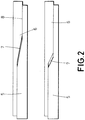
- Figure 2 illustrates how these porosity problems are originated by gaps (7) created between the fresh stack of plies (5) of composite material, and hard tooling areas of the metallic tool (6) in contact with said plies (5) once the metallic tool is positioned for the curing process.
- a fresh (not-cured) formed stack of plies (5) of carbon fiber is heated and pressed against a metallic mold (5) by the application of a vacuum, so that the stack of plies (5) is cured and at the same time compacted by the metallic tool (6).
- EP-1.238.785 A1 describes a tool according to the preamble of the attached claim 1.
- EP-1.031.406 A1 describes a tool for forming composite articles.
- German patent application DE-10 2009 023 864 A1 refers to a method for manufacturing of doppler from fiber composite material for surface section of component, which involves preparing device with flexible tool surface and illustrating surface section in tool surface.
- the present invention is defined in the attached independent claim, and satisfactorily solves the above-described problems of existing tooling for curing CFRP pieces with demanding thickness changes and/or minimum thickness, which cannot be manufactured using conventional metallic tools.
- Preferred embodiments of the invention are defined in the attached dependent claims.
- the invention refers to a hybrid tool suitable for curing pieces of composite material, wherein the tool has a contact surface with a shape form or adapted to substantially match the shape of a composite material part (formed at a previous stage) to be cured.
- Said contact surface is formed by two surfaces of a different nature, namely a metallic surface and an elastic surface arranged in the tool in correspondence with the section with minimum thickness and/or very aggressive thickness changes of the piece to be cured.
- the elastic surface is arranged in correspondence with the run-out section of the tool, and the metallic surface is arranged at an inner section of the tool.
- the metallic portion of the tool is a conventional metallic tool, usually made of invar, steel or any other kind of metallic material suitable for this purpose, which is similar to the tools of the prior art, and which extends over a major part of the tool except for the run-out section.
- the elastic portion of the tool is made of a material capable of elastically modifying its volume and shape, that is, a material which is deformed due to an external force and which returns to its original shape when the external force is removed.
- the elastic portion is provided on a part of the interior surface of the metallic portion, that is, on the surface of the metallic portion which is meant to be in contact with the CFRP piece to be cured along the run out section of the stringer to be cured, and in such a manner that the metallic portion acts as a support or substrate for the elastic portion.
- the elastic part is made of an elastomeric material, since the elastic and strength properties of this material, makes it suitable for this particular application.
- an aspect of this invention refers to a hybrid tool for curing pieces of composite material, comprising at least one metallic portion and an elastic portion provided on a surface of the metallic portion.
- the elastic and the metallic portions are permanently joined to each other, which means that both portions remain fixed to each other during and after a curing process. Additionally, the metallic and elastic portions are arranged relative to each other, in such a manner that they form together a contact surface with a shape which copies or reproduces at least part of surface of a piece of composite material to be cured.
- the hybrid tool can be repeatedly used in many curing cycles, without the need of readjusting the position of the elastic portions after each cycle.
- the elastic property of the elastic portion has the effect that porosity problems in the CFRP pieces to be obtained are prevented or at least significantly reduced.
- heat and pressure vacuum
- the vacuum applied causes the elastic portions to expand adapting its shape to the stack of plies and reducing therefore the volume of the cavities created between the tool and plies. Since the volume of those cavities is significantly reduced, any undesired flow of resin towards the cavities is prevented, thus, a pre-form of uncured composite piece with aggressive thickness change, can be cured satisfactorily.
- the hybrid tool of the present invention is provided with a deformable surface where the elastic portion is provided.
- Another object of the invention is a method for manufacturing composites structures of an aircraft, such as stringers, based on the use of the above-described hybrid tooling.
- the invention also refers to a stringer for an aircraft made of composite material, which satisfactorily solves the before-mentioned problems associated to the load transfer at the stringer run-out.
- One of the advantages of the invention is the capacity of manufacturing stringers with an aggressive drop off of plies, that is, an abrupt thickness diminution in both web and foot at the run-out section, achieving a thickness reduction of even 60-80% of the normal thickness or even less. These stringers can be manufactured repetitively with good quality.
- the hybrid tool of the invention can also be advantageously used for the manufacture of other CFRP structures of an aircraft, such as skin panels, which are susceptible of optimization through an aggressive drop off of plies.
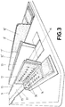
- Figure 3 shows an hybrid tool (14) for curing pieces of composite material according to a preferred embodiment of the invention, wherein the tool (14) includes first and second L-shaped parts (9, 9') which are symmetrical to each other, and are configured for curing a T-shaped stringer when they are coupled to each other as shown in figure 5 .
- Each of the L-shaped parts (9,9') comprises a metallic portion (15, 15' ) and an elastic portion (16,16') arranged on the inside surface of the respective metallic portions (15,15'), in such a manner that both portions (15,15',16, 16') together define a contact surface (17,17') meant to be in contact with a the composite part (25) (perform) to be cured.
- that contact surface (17,17') has a shape which copies at least part of a surface of a piece (25) of composite material.
- Figure 3 also shows a male mold (13), typically made of aluminium, arranged between the two L-shaped parts, which is used to form the elastic portion (16,16') over the respective metallic portion (15,15'), during the manufacturing process of the two parts (9, 9') of the.
- the male mold (13) reproduces the shape of the part to be cured, thus, it is manufactured with the desired slope or thickness reduction at its run-out section so that the elastic portion (16,16') is formed with the shape of that slope.
- the elastic portion (16,16') is made of an elastomeric material.
- Each of these two parts (9,9') of figure 3 is formed by a foot part (11) and a web part (10), and wherein the elastic portion (16) is provided on both, the inner surface of the web part (10) and on the inner surface of the foot part (15).
- the elastic portion (16) is arranged at the run-section of each part, that is, adjacent to an end of the same.
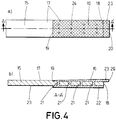
- the metallic portion (15) is an elongated body and the elastic portion (16) is arranged on an area of the metallic portion adjacent to one of its distal ends (18) (corresponding to the run-out section), so that these two portions are arranged to define or form together a working or contact surface (17) with the shape of a form composite piece to be cured (25), the contact surface (17) matches the shape of the outer surface of the web and foot parts of a T-shaped stringer.
- part of the metallic portion (15) acts as a back support for the elastic portion (16), and the thickness of the longitudinal cross-section of the elastic portion (16) increases from an interior end (19) to an exterior end (20) of the elastic portion (16), to form a slope with the required shape corresponding to the run-out section of a pre-formed stringer with an abrupt thickness reduction.
- the elastic portion (16) is in direct contact with a surface of the metallic portion (15), as shown more clearly in figure 4 , and it may be fixed to the metallic portion for example by means of an adhesive.
- the metallic and the elastic portions are configured in such a manner that they engage with each other to remain permanently fixed.
- that engagement is obtained by a plurality of perforations (21) through the metallic portion (15), so that part of the elastomeric material penetrates into those perforations (21) during the curing process of that material.
- the elastic portion (16) may extend beyond the distal end (18) of the metallic portion, to form a flap (23) which is not supported by the metallic portion.
- This flap (23) provided in both parts (9,9') of the tool, serves to close the chamber between these two parts during a curing process, in order to prevent the resin from flowing out of that chamber.
- the elastic portion (16,16') extends on the whole metallic portion (15), or at least on a major part of it, in order to avoid porosity problems in the whole extend of the composite piece to be cured not only at the run-out.
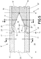
- An inner segment (26) is a conventional metallic tool, arranged in correspondence with a central part of the piece (25) to be cured.
- an outer segment (27) of the tool (14) is configured according to the invention, having an elastic portion (16, 16') formed with the shape of the run-out (28) of the piece (25).
- the two symmetrical metallic parts (30,30') of the outer segment (27), have a recessed area (31,31') for receiving the elastic portion (16, 16') as shown in figure 5 .
- the elastic portions (16,16') have a transition zone (32) where the interior surface of the elastic portions (16,16'), is flush with the interior surface of the inner segment (26).
- the elastic portions (16, 16') also have a run-out zone (33) shaped as a slope or ramp.
- the contact surface (17,17') of the tool (14), is formed by the interior surface of the metallic and the elastic portions (15,15',16,16').
- transition zone (32) in the elastic portions (16,16') has the effect and advantage that the zone more affected by the porosity problems, that is, the inflection zone (24) wherein the run-out zone (33) begins, is entirely formed by elastic material (16,16'), thus, porosity problems are reduced at the entire zone.
- These outer and inner segments (27,26) of the hybrid tool (14), are provided with an stepped configuration (29,29') at one of their ends, which are complementary to each other for coupling both segments.
- the contact surface (17,17') of the tool (14) is formed by the interior surface of the metallic and the elastic portions (15,15',16,16').
- the invention also refers to a method for manufacturing the before-described hybrid tool, which comprises the following steps:
- the present invention allows the manufacture of any kind of ramps for any kind of stiffener shape and in any section of the same, where the ramps are more aggressive or the thickness are bellow than those allowed by conventional metallic tooling.
- T-shaped stringers with abrupt ramps at their run-out (SRO) section can be manufactured using the hybrid tool of the invention, which in turn allows the optimization of the behavior of structures such as skin reinforced with stringers.
Landscapes
- Engineering & Computer Science (AREA)
- Manufacturing & Machinery (AREA)
- Mechanical Engineering (AREA)
- Moulding By Coating Moulds (AREA)
Claims (12)
- Outil hybride (14) destiné à permettre la polymérisation de pièces en matériau composite comprenant au moins une partie métallique (15, 15') et une partie élastique (16, 16') située sur une surface de la partie métallique (15, 15'), la partie élastique (16, 16') et la partie métallique (15, 15') étant en permanence liées l'une à l'autre, et la partie métallique et la partie élastique définissant ensemble une surface de contact (17, 17') ayant une forme reproduisant au moins une partie de la surface d'une pièce (25) en matériau synthétique devant être polymérisée, caractérisé en ce que
la partie élastique (16, 16') a une extrémité interne (19) située au niveau de la région interne de la partie métallique (15, 15') et une extrémité externe (20) située à proximité de l'extrémité distale de la partie métallique (15, 15'), et l'épaisseur de la partie élastique (16, 16') augmente graduellement de l'extrémité interne (19) vers l'extrémité externe (20). - Outil hybride conforme à la revendication 1,
dans lequel la partie élastique (16, 16') est réalisée en un matériau élastomère. - Outil hybride conforme à la revendication 1 ou 2,
dans lequel la partie métallique (15, 15') est constituée par un corps allongé et la partie élastique (16, 16') est située sur une zone de la partie métallique adjacente à l'extrémité distale de cette partie métallique. - Outil hybride conforme à l'une quelconque des revendications précédentes,
dans lequel la partie élastique (16, 16') chevauche une surface de la partie métallique (15, 15') et est en contact direct avec celle-ci et la partie élastique (16, 16') est liée mécaniquement ou collée à la partie métallique (15, 15'). - Outil hybride conforme aux revendications 1 et 2,
dans lequel le matériau élastomère a été mis en forme par moulage sur la partie métallique en le chauffant et le comprimant entre cette partie métallique et un moule mâle (13). - Outil hybride conforme à la revendication 1,
réalisé pour permettre la polymérisation de raidisseurs comprenant une base (11) et une ailette (10) faisant saillie sur la base (11) ainsi qu'un segment de sortie à l'une de ses extrémités, la partie métallique (15, 15') ayant une surface interne et une surface externe et la partie élastique (16, 16') étant située sur la surface interne de la partie métallique (15, 15'). - Outil hybride conforme à la revendication 6,
dans lequel la partie métallique a une section transversale en forme de L ayant une partie de base et une partie d'ailette, et la partie élastique est située à la fois sur la surface interne de la partie d'ailette et sur la partie de base de la partie métallique (15, 15'), la partie élastique (16, 16') étant située au niveau du segment d'extension de l'outil. - Outil hybride conforme à la revendication 6 ou 7,
dans lequel la partie métallique (15, 15') comprend un ensemble de perforations (21) s'étendant de la surface interne à la surface externe, l'outil (14) comprenant en outre une couche support (22) située sur sa surface externe essentiellement en regard de la partie élastique (16, 16') et la couche support (22) et la partie élastique (16, 16') étant réalisées dans le même matériau élastique et étant liées au travers des perforations (21). - Outil hybride conforme à l'une quelconque des revendications précédentes,
dans lequel les parties élastiques (16, 16') ont une zone de transition (32) dont la surface interne est alignée avec la surface interne de la partie métallique (15, 15'). - Outil hybride conforme à l'une quelconque des revendications précédentes,
dans lequel la partie métallique (15, 15') a une zone en retrait, et la partie élastique (16, 16') est située au niveau de cette zone en retrait. - Outil permettant de polymériser des pièces en matériau composite comprenant deux outils hybrides (14) conformes à l'une quelconque des revendications précédentes, ces deux outils hybrides étant symétriques.
- Utilisation d'un outil hybride conforme à l'une quelconque des revendications précédentes pour l'obtention de raidisseurs en matériau composite pour un avion.
Priority Applications (4)
| Application Number | Priority Date | Filing Date | Title |
|---|---|---|---|
| EP13169874.8A EP2808147B1 (fr) | 2013-05-30 | 2013-05-30 | Outil hybride pour le durcissement de pièces de matériau composite |
| ES13169874.8T ES2626352T3 (es) | 2013-05-30 | 2013-05-30 | Herramienta híbrida para curar piezas de material compuesto |
| US14/288,931 US10576723B2 (en) | 2013-05-30 | 2014-05-28 | Hybrid tool for curing pieces of composite material |
| CN201410239084.4A CN104210670B (zh) | 2013-05-30 | 2014-05-30 | 用于固化复合材料的工件的混合式工具 |
Applications Claiming Priority (1)
| Application Number | Priority Date | Filing Date | Title |
|---|---|---|---|
| EP13169874.8A EP2808147B1 (fr) | 2013-05-30 | 2013-05-30 | Outil hybride pour le durcissement de pièces de matériau composite |
Publications (2)
| Publication Number | Publication Date |
|---|---|
| EP2808147A1 EP2808147A1 (fr) | 2014-12-03 |
| EP2808147B1 true EP2808147B1 (fr) | 2017-03-01 |
Family
ID=48536721
Family Applications (1)
| Application Number | Title | Priority Date | Filing Date |
|---|---|---|---|
| EP13169874.8A Active EP2808147B1 (fr) | 2013-05-30 | 2013-05-30 | Outil hybride pour le durcissement de pièces de matériau composite |
Country Status (4)
| Country | Link |
|---|---|
| US (1) | US10576723B2 (fr) |
| EP (1) | EP2808147B1 (fr) |
| CN (1) | CN104210670B (fr) |
| ES (1) | ES2626352T3 (fr) |
Families Citing this family (12)
| Publication number | Priority date | Publication date | Assignee | Title |
|---|---|---|---|---|
| EP3088171B1 (fr) | 2015-04-30 | 2022-06-29 | Airbus Operations, S.L. | Procédé de fabrication de structures composites avec des outils de durcissement disposés à l'extérieur de la poche à vide |
| US9808988B2 (en) * | 2015-11-30 | 2017-11-07 | The Boeing Company | Carbon fiber reinforced plastic (CFRP) stringer termination softening with stacked CFRP noodle |
| CN108688192B (zh) * | 2017-04-12 | 2020-11-03 | 深圳市泰格尔航天航空科技有限公司 | 一种c型梁复合材料成型工装及复合材料c型梁成型方法 |
| CN109278316B (zh) * | 2017-07-21 | 2021-04-09 | 北京遥感设备研究所 | 一种碳纤维材料的t型结构件模压成型工艺方法 |
| GB2565350A (en) * | 2017-08-11 | 2019-02-13 | Airbus Operations Ltd | Panel assembly |
| GB2575103A (en) * | 2018-06-29 | 2020-01-01 | Airbus Operations Ltd | Method of manufacturing duct stringer |
| CN111113958B (zh) * | 2018-10-30 | 2021-07-09 | 中国商用飞机有限责任公司 | 一种长桁的定位方法及加筋壁板 |
| CN109591335A (zh) * | 2018-11-30 | 2019-04-09 | 长春长光宇航复合材料有限公司 | 一种复合材料产品成型过程中金属件的预埋方法 |
| US11084228B2 (en) * | 2019-04-08 | 2021-08-10 | Rohr, Inc. | Methods of joining and repairing composite components |
| CN110480884B (zh) * | 2019-08-22 | 2022-06-24 | 中国商用飞机有限责任公司北京民用飞机技术研究中心 | 模具、组装预成型结构的制造方法和壁板结构的制造方法 |
| FR3116755A1 (fr) * | 2020-11-30 | 2022-06-03 | Airbus Operations (S.A.S.) | Procédé de fabrication d’un panneau raidi comprenant des renforts avec des extrémités biseautées et panneau raidi obtenu à partir dudit procédé |
| CN114953505B (zh) * | 2022-05-24 | 2023-10-03 | 上海晟纤复合材料有限公司 | 一种复合材料加筋壁板长桁截止端成型方法 |
Family Cites Families (27)
| Publication number | Priority date | Publication date | Assignee | Title |
|---|---|---|---|---|
| US3343770A (en) * | 1965-07-26 | 1967-09-26 | Cellasto Inc | Bonding of an elastic shock absorber with a rigid base plate |
| US4331723A (en) * | 1980-11-05 | 1982-05-25 | The Boeing Company | Advanced composite |
| EP0299611A1 (fr) * | 1987-06-05 | 1989-01-18 | Takeda Chemical Industries, Ltd. | Appareil et procédé de moulage par compression |
| FR2638673B1 (fr) * | 1988-11-08 | 1991-03-22 | Aerospatiale | Outillage pour le moulage de panneaux auto-raidis en materiau composite |
| US5593633A (en) * | 1990-05-03 | 1997-01-14 | Dull; Kenneth M. | Edge and surface breather for high temperature composite processing |
| US5203940A (en) * | 1991-11-22 | 1993-04-20 | Phillips Petroleum Company | Method and apparatus for thermoforming plastic sheets |
| US5290499A (en) * | 1992-05-21 | 1994-03-01 | Davidson Textron Inc. | Apparatus and method for sealing a mold box |
| US6197146B1 (en) * | 1998-12-21 | 2001-03-06 | Sikorsky Aircraft Corporation | Method and apparatus for forming airfoil structures |
| EP1031406A1 (fr) * | 1999-02-22 | 2000-08-30 | British Aerospace | Fabrication des elements de renforcement |
| US6245275B1 (en) * | 1999-05-13 | 2001-06-12 | Vought Aircraft Industries, Inc. | Method for fabricating composite structures |
| US6523246B1 (en) * | 1999-11-26 | 2003-02-25 | Honda Giken Kogyo Kabushiki Kaisha | Jig used for formation of fiber-reinforced composite structure and method for formation of fiber-reinforced composite structure using jig |
| JP4425424B2 (ja) * | 2000-05-01 | 2010-03-03 | 本田技研工業株式会社 | 繊維強化複合材からなるジョグル付き半硬化物品の製造方法、及びそれを用いた予備成形構造体の製造方法 |
| JP4448242B2 (ja) * | 2000-09-05 | 2010-04-07 | 本田技研工業株式会社 | スティフンドパネル用成形補助治具 |
| EP1238785B1 (fr) * | 2001-03-05 | 2004-04-28 | Swiss Luggage SL AG | Procédé pour fabriquer un article profilé en forme de coque et moule utilisable pour celui-ci |
| US6840750B2 (en) * | 2001-06-11 | 2005-01-11 | The Boeing Company | Resin infusion mold tool system and vacuum assisted resin transfer molding with subsequent pressure bleed |
| FR2866626B1 (fr) | 2004-02-20 | 2006-05-19 | Airbus France | Arret de raidisseur a pentes decalees et panneau muni d'un tel arret |
| ES2277716B1 (es) | 2004-12-31 | 2008-05-16 | Airbus España, S.L. | Tapa reforzada para ranuras en un contorno aerodinamico. |
| DE102005044823B3 (de) | 2005-09-20 | 2007-05-16 | Airbus Gmbh | Verfahren und Vorrichtung zum Aufbringen dünner Materiallagen auf eine Reliefform |
| US8752293B2 (en) | 2007-12-07 | 2014-06-17 | The Boeing Company | Method of fabricating structures using composite modules and structures made thereby |
| DE102007061431B4 (de) * | 2007-12-20 | 2013-08-08 | Airbus Operations Gmbh | Verfahren zur Versteifung eines Faserverbundbauteils sowie Vakuummatte und Anordnung zur Herstellung eines versteiften Faserverbundbauteils |
| DE102007062872A1 (de) * | 2007-12-28 | 2009-07-09 | Airbus Deutschland Gmbh | Verfahren zur Herstellung eines Profils aus Faserverbundwerkstoff |
| DE102008001498B3 (de) * | 2008-04-30 | 2009-08-27 | Airbus Deutschland Gmbh | Verfahren und Umformvorrichtung zur Herstellung eines Faserverbundbauteils für die Luft- und Raumfahrt |
| DE102009023864B4 (de) * | 2009-06-04 | 2014-05-22 | Airbus Operations Gmbh | Vorrichtung und Verfahren zur Herstellung eines Dopplers |
| GB0912015D0 (en) | 2009-07-10 | 2009-08-19 | Airbus Operations Ltd | Stringer |
| ES2378682B1 (es) * | 2010-06-18 | 2013-02-28 | Airbus Operations, S.L. | Método de fabricación de larguerillos con forma de "t" para un avión y herramienta de curado usada en el mismo. |
| GB201016869D0 (en) * | 2010-10-07 | 2010-11-17 | Rolls Royce Plc | Methods and apparatus for forming a composite component |
| FR2979574B1 (fr) | 2011-09-07 | 2016-12-09 | Airbus Operations Sas | Procede de fabrication d'une structure comprenant une peau et des raidisseurs |
-
2013
- 2013-05-30 EP EP13169874.8A patent/EP2808147B1/fr active Active
- 2013-05-30 ES ES13169874.8T patent/ES2626352T3/es active Active
-
2014
- 2014-05-28 US US14/288,931 patent/US10576723B2/en active Active
- 2014-05-30 CN CN201410239084.4A patent/CN104210670B/zh active Active
Non-Patent Citations (1)
| Title |
|---|
| None * |
Also Published As
| Publication number | Publication date |
|---|---|
| CN104210670B (zh) | 2018-01-26 |
| ES2626352T3 (es) | 2017-07-24 |
| EP2808147A1 (fr) | 2014-12-03 |
| US10576723B2 (en) | 2020-03-03 |
| CN104210670A (zh) | 2014-12-17 |
| US20140352877A1 (en) | 2014-12-04 |
Similar Documents
| Publication | Publication Date | Title |
|---|---|---|
| EP2808147B1 (fr) | Outil hybride pour le durcissement de pièces de matériau composite | |
| US9669581B2 (en) | Method for manufacturing an aeronautical torsion box, torsion box and tool for manufacturing an aeronautical torsion box | |
| CN103448901B (zh) | 结合的复合翼面以及制造方法 | |
| EP2727711B1 (fr) | Remplissage de rayon composite et procédés de formation de celui-ci | |
| JP6490340B2 (ja) | 短繊維材料を含む空隙充填材を有する複合構造を作製する方法及びシステム | |
| CA2685478C (fr) | Caisson de torsion multi-longerons integre en materiau composite | |
| KR102069926B1 (ko) | 안정화 부재를 구비한 복합 구조물 | |
| EP2301840A2 (fr) | Structure d'aeronef integré de matériau composite | |
| EP2440392B1 (fr) | Procédé de production d'une structure d'avion comprenant un agent de remplissage de rayon nanorenforcé | |
| US8197625B2 (en) | Process of manufacturing composite structures with embedded precured tools | |
| EP2883687B1 (fr) | Procédé de fabrication de composants composites partiellement durcis | |
| CN104743095A (zh) | 复合材料制成的高度集成的灌注箱及制造方法 | |
| US10005267B1 (en) | Formation of complex composite structures using laminate templates | |
| JP2003072691A (ja) | 複合材翼の製造方法および複合材翼 | |
| US11220354B2 (en) | Composite fuselage assembly and methods to form the assembly | |
| EP2455214B1 (fr) | Procédé pour la fabrication d'un élément d'union pour raccorder des bords des panneaux en sandwich composites | |
| JP2018079915A (ja) | 開チャネルスチフナ | |
| JP7412136B2 (ja) | 一体的な補強パネルを含む複合材料からなるマルチリブウィングボックス(multi-ribbed wing box)を製造する方法 | |
| EP2962840A1 (fr) | Bord d'attaque pour surface portante d'aéronef et son procédé de fabrication | |
| EP2890546B1 (fr) | Procédé pour fixer des raidisseurs avec une surface et dispositif | |
| US9162417B2 (en) | Method of manufacturing a structure | |
| US20150064393A1 (en) | Laminate for joining parts, and method and system for joining parts | |
| US8870117B2 (en) | Composite aircraft frame | |
| US11267584B2 (en) | Method for manufacturing a rear section of an aircraft and aircraft rear section |
Legal Events
| Date | Code | Title | Description |
|---|---|---|---|
| PUAI | Public reference made under article 153(3) epc to a published international application that has entered the european phase |
Free format text: ORIGINAL CODE: 0009012 |
|
| 17P | Request for examination filed |
Effective date: 20130530 |
|
| AK | Designated contracting states |
Kind code of ref document: A1 Designated state(s): AL AT BE BG CH CY CZ DE DK EE ES FI FR GB GR HR HU IE IS IT LI LT LU LV MC MK MT NL NO PL PT RO RS SE SI SK SM TR |
|
| AX | Request for extension of the european patent |
Extension state: BA ME |
|
| R17P | Request for examination filed (corrected) |
Effective date: 20150601 |
|
| RBV | Designated contracting states (corrected) |
Designated state(s): AL AT BE BG CH CY CZ DE DK EE ES FI FR GB GR HR HU IE IS IT LI LT LU LV MC MK MT NL NO PL PT RO RS SE SI SK SM TR |
|
| GRAP | Despatch of communication of intention to grant a patent |
Free format text: ORIGINAL CODE: EPIDOSNIGR1 |
|
| RIC1 | Information provided on ipc code assigned before grant |
Ipc: B29C 70/44 20060101ALN20161006BHEP Ipc: B29L 31/00 20060101ALN20161006BHEP Ipc: B29C 33/40 20060101AFI20161006BHEP Ipc: B29C 70/34 20060101ALN20161006BHEP Ipc: B29L 31/30 20060101ALN20161006BHEP Ipc: B29C 33/38 20060101ALI20161006BHEP |
|
| INTG | Intention to grant announced |
Effective date: 20161026 |
|
| RIN1 | Information on inventor provided before grant (corrected) |
Inventor name: CEBOLLA GARROFE, PABLO Inventor name: GALIANA BLANCO, JORGE JUAN Inventor name: ROMON BANOGON, CARLOS Inventor name: FERNANDEZ ALONSO, ALEJANDRO Inventor name: GARCIA GARCIA, AQUILINO |
|
| STAA | Information on the status of an ep patent application or granted ep patent |
Free format text: STATUS: GRANT OF PATENT IS INTENDED |
|
| GRAS | Grant fee paid |
Free format text: ORIGINAL CODE: EPIDOSNIGR3 |
|
| GRAA | (expected) grant |
Free format text: ORIGINAL CODE: 0009210 |
|
| STAA | Information on the status of an ep patent application or granted ep patent |
Free format text: STATUS: THE PATENT HAS BEEN GRANTED |
|
| AK | Designated contracting states |
Kind code of ref document: B1 Designated state(s): AL AT BE BG CH CY CZ DE DK EE ES FI FR GB GR HR HU IE IS IT LI LT LU LV MC MK MT NL NO PL PT RO RS SE SI SK SM TR |
|
| REG | Reference to a national code |
Ref country code: GB Ref legal event code: FG4D |
|
| REG | Reference to a national code |
Ref country code: CH Ref legal event code: EP Ref country code: AT Ref legal event code: REF Ref document number: 870751 Country of ref document: AT Kind code of ref document: T Effective date: 20170315 |
|
| REG | Reference to a national code |
Ref country code: IE Ref legal event code: FG4D |
|
| REG | Reference to a national code |
Ref country code: DE Ref legal event code: R096 Ref document number: 602013017866 Country of ref document: DE |
|
| REG | Reference to a national code |
Ref country code: FR Ref legal event code: PLFP Year of fee payment: 5 |
|
| REG | Reference to a national code |
Ref country code: NL Ref legal event code: MP Effective date: 20170301 |
|
| REG | Reference to a national code |
Ref country code: LT Ref legal event code: MG4D |
|
| REG | Reference to a national code |
Ref country code: AT Ref legal event code: MK05 Ref document number: 870751 Country of ref document: AT Kind code of ref document: T Effective date: 20170301 |
|
| REG | Reference to a national code |
Ref country code: ES Ref legal event code: FG2A Ref document number: 2626352 Country of ref document: ES Kind code of ref document: T3 Effective date: 20170724 |
|
| PG25 | Lapsed in a contracting state [announced via postgrant information from national office to epo] |
Ref country code: HR Free format text: LAPSE BECAUSE OF FAILURE TO SUBMIT A TRANSLATION OF THE DESCRIPTION OR TO PAY THE FEE WITHIN THE PRESCRIBED TIME-LIMIT Effective date: 20170301 Ref country code: NO Free format text: LAPSE BECAUSE OF FAILURE TO SUBMIT A TRANSLATION OF THE DESCRIPTION OR TO PAY THE FEE WITHIN THE PRESCRIBED TIME-LIMIT Effective date: 20170601 Ref country code: GR Free format text: LAPSE BECAUSE OF FAILURE TO SUBMIT A TRANSLATION OF THE DESCRIPTION OR TO PAY THE FEE WITHIN THE PRESCRIBED TIME-LIMIT Effective date: 20170602 Ref country code: LT Free format text: LAPSE BECAUSE OF FAILURE TO SUBMIT A TRANSLATION OF THE DESCRIPTION OR TO PAY THE FEE WITHIN THE PRESCRIBED TIME-LIMIT Effective date: 20170301 Ref country code: FI Free format text: LAPSE BECAUSE OF FAILURE TO SUBMIT A TRANSLATION OF THE DESCRIPTION OR TO PAY THE FEE WITHIN THE PRESCRIBED TIME-LIMIT Effective date: 20170301 |
|
| PG25 | Lapsed in a contracting state [announced via postgrant information from national office to epo] |
Ref country code: LV Free format text: LAPSE BECAUSE OF FAILURE TO SUBMIT A TRANSLATION OF THE DESCRIPTION OR TO PAY THE FEE WITHIN THE PRESCRIBED TIME-LIMIT Effective date: 20170301 Ref country code: BG Free format text: LAPSE BECAUSE OF FAILURE TO SUBMIT A TRANSLATION OF THE DESCRIPTION OR TO PAY THE FEE WITHIN THE PRESCRIBED TIME-LIMIT Effective date: 20170601 Ref country code: AT Free format text: LAPSE BECAUSE OF FAILURE TO SUBMIT A TRANSLATION OF THE DESCRIPTION OR TO PAY THE FEE WITHIN THE PRESCRIBED TIME-LIMIT Effective date: 20170301 Ref country code: RS Free format text: LAPSE BECAUSE OF FAILURE TO SUBMIT A TRANSLATION OF THE DESCRIPTION OR TO PAY THE FEE WITHIN THE PRESCRIBED TIME-LIMIT Effective date: 20170301 Ref country code: LU Free format text: LAPSE BECAUSE OF NON-PAYMENT OF DUE FEES Effective date: 20170531 Ref country code: SE Free format text: LAPSE BECAUSE OF FAILURE TO SUBMIT A TRANSLATION OF THE DESCRIPTION OR TO PAY THE FEE WITHIN THE PRESCRIBED TIME-LIMIT Effective date: 20170301 |
|
| PG25 | Lapsed in a contracting state [announced via postgrant information from national office to epo] |
Ref country code: NL Free format text: LAPSE BECAUSE OF FAILURE TO SUBMIT A TRANSLATION OF THE DESCRIPTION OR TO PAY THE FEE WITHIN THE PRESCRIBED TIME-LIMIT Effective date: 20170301 |
|
| PG25 | Lapsed in a contracting state [announced via postgrant information from national office to epo] |
Ref country code: CZ Free format text: LAPSE BECAUSE OF FAILURE TO SUBMIT A TRANSLATION OF THE DESCRIPTION OR TO PAY THE FEE WITHIN THE PRESCRIBED TIME-LIMIT Effective date: 20170301 Ref country code: SK Free format text: LAPSE BECAUSE OF FAILURE TO SUBMIT A TRANSLATION OF THE DESCRIPTION OR TO PAY THE FEE WITHIN THE PRESCRIBED TIME-LIMIT Effective date: 20170301 Ref country code: RO Free format text: LAPSE BECAUSE OF FAILURE TO SUBMIT A TRANSLATION OF THE DESCRIPTION OR TO PAY THE FEE WITHIN THE PRESCRIBED TIME-LIMIT Effective date: 20170301 Ref country code: EE Free format text: LAPSE BECAUSE OF FAILURE TO SUBMIT A TRANSLATION OF THE DESCRIPTION OR TO PAY THE FEE WITHIN THE PRESCRIBED TIME-LIMIT Effective date: 20170301 Ref country code: IT Free format text: LAPSE BECAUSE OF FAILURE TO SUBMIT A TRANSLATION OF THE DESCRIPTION OR TO PAY THE FEE WITHIN THE PRESCRIBED TIME-LIMIT Effective date: 20170301 |
|
| PG25 | Lapsed in a contracting state [announced via postgrant information from national office to epo] |
Ref country code: IS Free format text: LAPSE BECAUSE OF FAILURE TO SUBMIT A TRANSLATION OF THE DESCRIPTION OR TO PAY THE FEE WITHIN THE PRESCRIBED TIME-LIMIT Effective date: 20170701 Ref country code: SM Free format text: LAPSE BECAUSE OF FAILURE TO SUBMIT A TRANSLATION OF THE DESCRIPTION OR TO PAY THE FEE WITHIN THE PRESCRIBED TIME-LIMIT Effective date: 20170301 Ref country code: PL Free format text: LAPSE BECAUSE OF FAILURE TO SUBMIT A TRANSLATION OF THE DESCRIPTION OR TO PAY THE FEE WITHIN THE PRESCRIBED TIME-LIMIT Effective date: 20170301 Ref country code: PT Free format text: LAPSE BECAUSE OF FAILURE TO SUBMIT A TRANSLATION OF THE DESCRIPTION OR TO PAY THE FEE WITHIN THE PRESCRIBED TIME-LIMIT Effective date: 20170703 |
|
| REG | Reference to a national code |
Ref country code: DE Ref legal event code: R097 Ref document number: 602013017866 Country of ref document: DE |
|
| REG | Reference to a national code |
Ref country code: CH Ref legal event code: PL |
|
| PLBE | No opposition filed within time limit |
Free format text: ORIGINAL CODE: 0009261 |
|
| STAA | Information on the status of an ep patent application or granted ep patent |
Free format text: STATUS: NO OPPOSITION FILED WITHIN TIME LIMIT |
|
| PG25 | Lapsed in a contracting state [announced via postgrant information from national office to epo] |
Ref country code: MC Free format text: LAPSE BECAUSE OF FAILURE TO SUBMIT A TRANSLATION OF THE DESCRIPTION OR TO PAY THE FEE WITHIN THE PRESCRIBED TIME-LIMIT Effective date: 20170301 Ref country code: DK Free format text: LAPSE BECAUSE OF FAILURE TO SUBMIT A TRANSLATION OF THE DESCRIPTION OR TO PAY THE FEE WITHIN THE PRESCRIBED TIME-LIMIT Effective date: 20170301 |
|
| 26N | No opposition filed |
Effective date: 20171204 |
|
| REG | Reference to a national code |
Ref country code: IE Ref legal event code: MM4A |
|
| PG25 | Lapsed in a contracting state [announced via postgrant information from national office to epo] |
Ref country code: LI Free format text: LAPSE BECAUSE OF NON-PAYMENT OF DUE FEES Effective date: 20170531 Ref country code: CH Free format text: LAPSE BECAUSE OF NON-PAYMENT OF DUE FEES Effective date: 20170531 Ref country code: SI Free format text: LAPSE BECAUSE OF FAILURE TO SUBMIT A TRANSLATION OF THE DESCRIPTION OR TO PAY THE FEE WITHIN THE PRESCRIBED TIME-LIMIT Effective date: 20170301 |
|
| PG25 | Lapsed in a contracting state [announced via postgrant information from national office to epo] |
Ref country code: LU Free format text: LAPSE BECAUSE OF NON-PAYMENT OF DUE FEES Effective date: 20170530 |
|
| REG | Reference to a national code |
Ref country code: BE Ref legal event code: MM Effective date: 20170531 |
|
| PG25 | Lapsed in a contracting state [announced via postgrant information from national office to epo] |
Ref country code: IE Free format text: LAPSE BECAUSE OF NON-PAYMENT OF DUE FEES Effective date: 20170530 |
|
| REG | Reference to a national code |
Ref country code: FR Ref legal event code: PLFP Year of fee payment: 6 |
|
| PG25 | Lapsed in a contracting state [announced via postgrant information from national office to epo] |
Ref country code: BE Free format text: LAPSE BECAUSE OF NON-PAYMENT OF DUE FEES Effective date: 20170531 |
|
| PG25 | Lapsed in a contracting state [announced via postgrant information from national office to epo] |
Ref country code: MT Free format text: LAPSE BECAUSE OF NON-PAYMENT OF DUE FEES Effective date: 20170530 |
|
| PG25 | Lapsed in a contracting state [announced via postgrant information from national office to epo] |
Ref country code: HU Free format text: LAPSE BECAUSE OF FAILURE TO SUBMIT A TRANSLATION OF THE DESCRIPTION OR TO PAY THE FEE WITHIN THE PRESCRIBED TIME-LIMIT; INVALID AB INITIO Effective date: 20130530 |
|
| PG25 | Lapsed in a contracting state [announced via postgrant information from national office to epo] |
Ref country code: CY Free format text: LAPSE BECAUSE OF FAILURE TO SUBMIT A TRANSLATION OF THE DESCRIPTION OR TO PAY THE FEE WITHIN THE PRESCRIBED TIME-LIMIT Effective date: 20170301 |
|
| PG25 | Lapsed in a contracting state [announced via postgrant information from national office to epo] |
Ref country code: MK Free format text: LAPSE BECAUSE OF FAILURE TO SUBMIT A TRANSLATION OF THE DESCRIPTION OR TO PAY THE FEE WITHIN THE PRESCRIBED TIME-LIMIT Effective date: 20170301 |
|
| PG25 | Lapsed in a contracting state [announced via postgrant information from national office to epo] |
Ref country code: TR Free format text: LAPSE BECAUSE OF FAILURE TO SUBMIT A TRANSLATION OF THE DESCRIPTION OR TO PAY THE FEE WITHIN THE PRESCRIBED TIME-LIMIT Effective date: 20170301 |
|
| PG25 | Lapsed in a contracting state [announced via postgrant information from national office to epo] |
Ref country code: AL Free format text: LAPSE BECAUSE OF FAILURE TO SUBMIT A TRANSLATION OF THE DESCRIPTION OR TO PAY THE FEE WITHIN THE PRESCRIBED TIME-LIMIT Effective date: 20170301 |
|
| PGFP | Annual fee paid to national office [announced via postgrant information from national office to epo] |
Ref country code: FR Payment date: 20230526 Year of fee payment: 11 Ref country code: DE Payment date: 20230519 Year of fee payment: 11 |
|
| PGFP | Annual fee paid to national office [announced via postgrant information from national office to epo] |
Ref country code: GB Payment date: 20230524 Year of fee payment: 11 Ref country code: ES Payment date: 20230725 Year of fee payment: 11 |