EP2808104A1 - Casting valve with a final compression piston - Google Patents
Casting valve with a final compression piston Download PDFInfo
- Publication number
- EP2808104A1 EP2808104A1 EP14167787.2A EP14167787A EP2808104A1 EP 2808104 A1 EP2808104 A1 EP 2808104A1 EP 14167787 A EP14167787 A EP 14167787A EP 2808104 A1 EP2808104 A1 EP 2808104A1
- Authority
- EP
- European Patent Office
- Prior art keywords
- valve
- casting
- piston
- pouring
- melt
- Prior art date
- Legal status (The legal status is an assumption and is not a legal conclusion. Google has not performed a legal analysis and makes no representation as to the accuracy of the status listed.)
- Granted
Links
Images

Classifications
-
- B—PERFORMING OPERATIONS; TRANSPORTING
- B22—CASTING; POWDER METALLURGY
- B22D—CASTING OF METALS; CASTING OF OTHER SUBSTANCES BY THE SAME PROCESSES OR DEVICES
- B22D27/00—Treating the metal in the mould while it is molten or ductile ; Pressure or vacuum casting
- B22D27/09—Treating the metal in the mould while it is molten or ductile ; Pressure or vacuum casting by using pressure
- B22D27/11—Treating the metal in the mould while it is molten or ductile ; Pressure or vacuum casting by using pressure making use of mechanical pressing devices
-
- B—PERFORMING OPERATIONS; TRANSPORTING
- B22—CASTING; POWDER METALLURGY
- B22D—CASTING OF METALS; CASTING OF OTHER SUBSTANCES BY THE SAME PROCESSES OR DEVICES
- B22D17/00—Pressure die casting or injection die casting, i.e. casting in which the metal is forced into a mould under high pressure
- B22D17/20—Accessories: Details
- B22D17/2015—Means for forcing the molten metal into the die
- B22D17/2069—Exerting after-pressure on the moulding material
-
- B—PERFORMING OPERATIONS; TRANSPORTING
- B22—CASTING; POWDER METALLURGY
- B22D—CASTING OF METALS; CASTING OF OTHER SUBSTANCES BY THE SAME PROCESSES OR DEVICES
- B22D17/00—Pressure die casting or injection die casting, i.e. casting in which the metal is forced into a mould under high pressure
- B22D17/20—Accessories: Details
- B22D17/2015—Means for forcing the molten metal into the die
- B22D17/203—Injection pistons
-
- B—PERFORMING OPERATIONS; TRANSPORTING
- B22—CASTING; POWDER METALLURGY
- B22D—CASTING OF METALS; CASTING OF OTHER SUBSTANCES BY THE SAME PROCESSES OR DEVICES
- B22D17/00—Pressure die casting or injection die casting, i.e. casting in which the metal is forced into a mould under high pressure
- B22D17/20—Accessories: Details
- B22D17/2076—Cutting-off equipment for sprues or ingates
-
- B—PERFORMING OPERATIONS; TRANSPORTING
- B22—CASTING; POWDER METALLURGY
- B22D—CASTING OF METALS; CASTING OF OTHER SUBSTANCES BY THE SAME PROCESSES OR DEVICES
- B22D17/00—Pressure die casting or injection die casting, i.e. casting in which the metal is forced into a mould under high pressure
- B22D17/20—Accessories: Details
- B22D17/30—Accessories for supplying molten metal, e.g. in rations
Definitions
- the invention relates to a pouring valve for supplying melt of a casting device with a valve housing, which has a melt channel connection as inlet and a valve outlet as outlet, with a valve cell for receiving the melt and with a closing means for changing the Ventilauslassqueritess Structure.
- the invention further relates to a casting apparatus with such a casting valve and a casting method for producing castings with this casting apparatus.
- DE 10 2007 047 545 A1 discloses a pouring valve which is closable by means of a piston.
- the piston is axially movable in a valve housing. This gap accuracy due to concentricity errors of the piston does not lead to inhomogeneous mass flows and a reliable closing of the pouring valve is ensured, the piston skirt surface has a larger angle to the valve main axis than the valve housing in the outlet region. In the closed state, the piston thus forms an annular bearing surface with the housing wall.
- Both latter casting valves can be used to reliably fill a casting cavity with a predetermined amount of melt.
- melt must continue to be supplied.
- the above-mentioned pouring valves can not close until the shrinking process has been completed, which requires heating at least until they close and makes precise metering more difficult.
- a second mechanism is required which fills and recompresses the hollow volume resulting from the shrinkage process by means of a melt replenishment.
- the pouring valve and the Nachverdichtungsmechanismus must be coordinated with each other, which is complex, the caster can be built expansively and thus increases the energy required for heating.
- Object of the present invention to improve the prior art and in particular to provide a pouring valve for a casting apparatus, which avoids the disadvantages mentioned above. Furthermore, it is a particular object of the invention to provide a die-casting method for metallic melts, which enables rapid casting while minimizing the supply of heat.
- a pouring valve for supplying melt of a pouring device, wherein the pouring valve comprises a valve housing having a melt channel connection as inlet and a valve outlet as outlet, a valve cell for receiving the melt and a closing means for changing the Ventilauslassqueritess Structure and wherein the valve cell can be connected via a melt channel connection with a melt channel, which can be prestressed by means of casting pressure, and the casting valve has a recompression piston for recompressing the melt after the mold has been filled.
- the integration of the recompression piston as squeeze pin in the pouring valve space-saving arrangement is created, which emits relatively little heat due to their compactness. Due to the fact that the melt for the filling of the casting cavity and the melt for recompression come from the same valve cell or according to the valve outlet downstream of the valve cell, the number of required heating means and pipelines can also be kept low.
- the valve cell of the casting valve can be connected to a melt reservoir or a casting chamber via the melt channel connection. If the pouring valve is part of a die casting device, the melt channel connection, the valve cell and the valve outlet are pressure-resistant.
- the valve cell can also have a plurality of melt channel connections, via which the melt can flow.
- valve cell has a plurality of melt channel connections, it can be provided that the melt flows out again during casting via at least one channel.
- the valve cell thus does not form the end of the melt channel, but is also flowed through by melt during the casting process, which does not leave the pouring valve via the valve outlet.
- the heating means which is arranged in or on the casting valve can be made smaller or possibly omitted entirely.
- the pouring valve may be integrated into the die-cast channel such that the valve cell passes through a part of the melt channel can be prestressed by means of casting pressure.
- the valve cell may have a storage volume, which is advantageously completely enclosed by the valve housing, so that it can be heated as located in the casting valve hot cell. An unwanted solidification can be easily avoided.
- valve cell occupies a certain volume;
- the pouring valve can be integrated in a melt channel particularly well if the cross-sectional area of the valve cell corresponds to the sum of the cross-sectional areas of the feeding melt channel connections. In this case, it is not enlarged in diameter compared to the melt channel and thus provides no additional volume
- the pouring valve preferably has as closing means a valve piston which is movable axially in the direction of the valve outlet and can close it.
- the valve housing and the valve piston are preferably designed so that the diameter of the effective Ventilauslassqueritess founded is steadily reduced when ancestors of the valve piston.
- the effective Ventilauslassqueritess simulation is the surface which is flowed through during the casting vertically from the melt.
- valve piston and the valve piston enclosing housing portion preferably form a conical valve seat.
- At least one of the two components valve piston or housing wall thus has a chamfer or a chamfer in such a way that the Ventilauslassqueritess Structure tapers in the direction of the valve outlet.
- the melt flow can take place through an annular opening which allows a relatively vortex-free melt flow. The effect is exacerbated when both components, the valve piston lateral surface and the housing bottom are seen in the sectional view provided with bevels.
- the bevels do not necessarily have to be conical.
- the housing inner wall or the piston skirt surface may be partially conical or curved in the axial direction. If the piston skirt surface or the valve seat are crowned, concentricity errors of the valve piston can be compensated particularly well, so that despite possible gap dimensions, the mass flow in the closed state is minimized.
- the crown also causes a line contact to form between these components when closing. Jamming of the valve piston can be reliably prevented by the thus lack of surface contact and possibly remaining between the surfaces solidifying melt material, which prevents damage to the valve piston and the valve housing. In the valve gap may have penetrated melt material due to the temperature gradient to the environment cool down and melted at the valve opening for the next casting process again.
- valve piston and the housing wall may be formed in the axial direction specific to the casting so that the tapering valve outlet cross-sectional area formed by the two components is designed so that the desired mold filling speed can be influenced by moving the valve piston.
- a large flow cross-section may be provided, which is required for the rapid filling of the casting cavity and to avoid trapped air, which is reduced with increasing degree of filling according to the shape of the casting cavity.
- the valve piston has a variable diameter over its axial length, with a correspondingly shaped valve housing, only a temporary reduction in the flow cross-section can take place, which is widened again before the final closing of the pouring valve.
- valve piston and the valve outlet are preferably arranged centrally in the valve housing.
- the valve piston drive can connect to the side facing away from the valve outlet and be integrated into the housing of the pouring valve. If the secondary compression piston can be moved via a separate drive, this can also be integrated into the valve housing.
- the melt channel connection In order to prevent a temperature drop of the melt and thus unwanted crystallization processes, can the melt channel connection, the valve outlet or other melt-contacting areas can be made heatable in the pouring valve. Each melting section is preferably heated separately.
- An electrically operated heater has a low inertia behavior and allows good control or regulation of the heating power.
- the channel walls themselves may be heated or covered by coils.
- the valve cell can also be heated.
- the valve piston also takes over the function of Nachverêtns.
- the same component then forms both the closing piston and the Nachverdichtungskolben.
- the valve piston is designed, for example, as a circular cylinder which forms a valve seat with a valve housing wall.
- the valve housing wall can initially be conical and then tubular, so that the valve piston initially throttles the melt flow when moving into the tubular section, closes the valve upon reaching the tubular section, and then recompresses during the process within the tubular section.
- the casting valve on two pistons which are at least temporarily movable relative to each other.
- the first piston is formed by the valve piston, with which the pouring valve is closable, and the second piston is designed as a secondary compression piston separately from the valve piston.
- the two pistons are arranged coaxially with each other, wherein the Nachverdichtungskolben is located inside.
- the housing wall is designed so that the valve piston in this Can move arrangement on the valve wall, is prevented from further movement and due to the smaller diameter of the Nachverdichtungskolbens whose further movement still possible.
- the secondary compression piston may have its own piston drive for the relative movement to the valve piston. As a result, it can be controlled separately from the valve piston, and it can be matched in its performance to the recompression.
- piston actuators for the Nachverdichtungskolben and the valve piston for example, hydraulic drives or electric spindles come into question.
- the two piston drives can also be formed by different drive types.
- a particularly compact pouring valve can be achieved if both pistons are movable by the same drive. Via drive valves or other control mechanisms it can be provided that only one of the pistons or both pistons are displaced simultaneously at a certain point in time. If a relative displacement is undesirable, at least in phases, as in the closing of the pouring valve, both pistons can also be connected to one another by suitable coupling means, so that they can only be moved together.
- the two pistons are coupled to each other and can only be moved to each other by increased effort. As long as the valve piston has not moved to block and thus closes the valve seat on the valve, then move both pistons together. By the then leaps and bounds increasing force dissolves the Nachverdichtungskolben of the valve piston and can then be moved alone. A piston drive is sufficient for this variant. A complex control unit is not required in this embodiment.
- the piston drive is preferably carried out hydraulically and is arranged for thermal reasons on the opposite side of the valve outlet.
- the pouring valve may have the pressure force transmitting decoupling means.
- the decoupling means are disposed between the piston heads and the piston drives and may be formed by ceramic layers or other sufficiently strong thermal insulators.
- the heat transfer can be reduced by a suitable mechanical structure.
- thin-walled intermediate bolts which connect the piston head to the piston drive, transmit less total heat and allow the arrangement of coolants in the spaces thus created.
- the pouring valve according to the invention is preferably installed in a die casting apparatus for metallic melts, but can also be used in other casting methods, such as in continuous casting or casting of non-metallic melts.
- the amount of circulating material is thereby reduces filling and recompression via the same pouring valve.
- a casting device preferably has the pouring valve according to the invention directly on the gate area of the casting or on the casting itself.
- the proportion of Sprue and the amount of circulating material can be further reduced.
- casting compositions of less than 20% of the casting mass can be achieved thereby.
- the sprue system can be compact.
- the sprue material can be reused as circulating material. The fact that less sprue material must be melted and the hot melt in the loop is always close to the mold cavity available, less time for the casting cycle is required, so that the timing is improved.
- the invention also relates to a method for die casting with a die casting device and a valve piston having a casting valve, which provides the following steps: providing a cleaned and prepared for a mold filling casting cavity with a closed pouring valve, opening the pouring valve for pouring, closing the pouring valve after Form Sprintde, removing the Casting and re-compression during the cooling process and before the removal of the casting by means of a built-in the pouring valve piston.
- the proposed method allows the filling and the recompression via the same gate opening, so that the number of gate areas is reduced compared to separately arranged to the casting valve squeeze pins.
- the required post-processing of the casting is thus reduced.
- FIG. 1 schematically shows a part of a casting apparatus 1 for die casting of metallic melts 2 such as magnesium or aluminum melts.
- the casting apparatus 1 has a casting chamber 4, which can be filled from a melt reservoir, not shown, via a melt valve 19.
- the melt 2 is conveyed from the horizontally oriented casting chamber 4 by a hydraulically moved, in the horizontal advancing casting piston 6 in a melt channel 11 and pressurized.
- the melt channel 11 is surrounded by heating means 5 in the form of coils, which prevent cooling of the melt 2. From the heated melt channel 11, the melt 2 passes through a melt channel connection 12 into the valve cell 8 (FIG. FIG. 2 ) of the pouring valve 7 and from there via the valve outlet 10 into the casting cavity 3.
- the casting cavity 3 itself is formed by two half-molds 15, 16 and is formed in a known manner by the enlarged by the Schwindmann negative mold of the casting to be produced.
- the half-molds 15, 16 are separable from each other at a parting surface 9, so that the finished casting can be removed.
- FIG. 2 shows a pouring valve 7 with a valve housing 13 which has a fillable via the melt channel connection 12 valve cell 8, which is part of the melt channel 11 itself and in comparison to this and the melt channel connection 12 has no enlarged cross-section.
- the valve piston 14 Centrally in the valve housing 13, the valve piston 14 is arranged, via which the valve outlet 10 is closed.
- the inner wall 21 of the valve housing 13, which adjoins the Ventilauslass 10 has an inclination relative to the main valve axis 22, which is greater than that of the lateral surface 18.
- valve piston 14 is driven by a first piston drive 24, which operates hydraulically and is arranged axially offset from the valve piston 14. Since the valve piston 14 is in contact with the hot melt 2, decoupling means 26 are provided in the form of intermediate bolts as spacers mechanically and thus thermally decouple the piston drive 24 with the piston plate 28 from the piston head 29 of the valve piston 14, but the pressure force on the Nevertheless, piston head 29 is transferred.
- the valve piston 14 is formed as a hollow cylinder and has co-axial to the direction of a Nachverdichtungskolben 23.
- the recompression piston 23 has a second piston drive 25 which is operable independently of the first piston drive 24. Its hydraulic chambers 30 are connected axially to those of the first piston drive 24.
- the casting cavity 3 is closed so tightly that it withstands the melt pressure of the subsequent die casting process.
- the inner recompression piston 23 returns to its starting position, which is set back so far from the valve piston 14 closing the valve outlet 10 that a blind hole 27 is created between the inner walls of the valve piston 14.
- the blind hole depth corresponds approximately to the stroke of the valve piston 14th
- valve piston 14 By retracting the valve piston 14, the actual casting process is initiated as a third phase.
- the valve piston 14 releases from its annular valve seat, and by the now flowing, hot melt 2 is possibly at this point cooled material melted. Due to the ring-line contact and any heating located on the pouring valve 7, the solidified amount of melt is so small that it is completely melted and does not make opening the valve piston 14 difficult or only insignificantly difficult.
- the valve outlet 10 is opened to the maximum, and the melt 2 can flow annularly between the pistons 14, 23 and the inner wall 21 of the valve housing 13 in the Gussteilkavmaschine 3. The envisaged for filling amount of melt is pushed by the advancing casting piston 6 via the melt channel 11.
- the casting solidifies and the casting chamber 4 is prepared for a new mold filling operation.
- the consequent shrinkage of material is compensated for by the secondary compression piston 23 which presses the melt 2 located in the blind hole 27 and the immediately adjacent region into the casting cavity. If the amount of melt required for the re-compaction 2 the Blind hole volume corresponds, the adjoining the valve outlet 10 runner can be particularly short or possibly even eliminated.
- the solidification process can be accelerated by supplying cooling power via cooling channels.
Abstract
Die Erfindung betrifft ein Gießventil zur Zuführung von Schmelzen einer Gießvorrichtung mit einem Ventilgehäuse, das einen Schmelzekanalanschluss und einen Ventilauslass aufweist, mit einem Ventilkolben zur Veränderung der Ventilauslassquerschnittsfläche und mit einer Ventilzelle zur Aufnahme der Schmelze, die über einen Schmelzekanalanschluss mit einem mittels Gießdruck vorspannbaren Schmelzekanal verbindbar ist. Das Gießventil weist einen integrierten Squeeze-Pin als Nachverdichtungskolben zur Nachspeisung und -verdichtung der Schmelze nach Formfüllende auf. Die Erfindung betrifft ebenfalls ein Verfahren zum Druckgießen mit dieser Gießvorrichtung, die ein derartiges Gießventil aufweist.The invention relates to a pouring valve for feeding melt of a casting device with a valve housing having a melt channel connection and a valve outlet, with a valve piston for changing the Ventilauslassquerschnittsfläche and with a valve cell for receiving the melt, which can be connected via a melt channel connection with a pre-stressed by pouring melt channel is. The pouring valve has an integrated squeeze pin as Nachverdichtungskolben for Nachspeisung and compression of the melt after Formfüllende. The invention also relates to a method for die casting with this casting apparatus having such a pouring valve.
Description
Die Erfindung betrifft ein Gießventil zur Zuführung von Schmelzen einer Gießvorrichtung mit einem Ventilgehäuse, das einen Schmelzekanalanschluss als Zulauf und einen Ventilauslass als Auslauf aufweist, mit einer Ventilzelle zur Aufnahme der Schmelze und mit einem Schließmittel zur Veränderung der Ventilauslassquerschnittsfläche. Die Erfindung betrifft weiterhin eine Gießvorrichtung mit einem derartigen Gießventil und ein Gießverfahren zur Herstellung von Gussteilen mit dieser Gießvorrichtung.The invention relates to a pouring valve for supplying melt of a casting device with a valve housing, which has a melt channel connection as inlet and a valve outlet as outlet, with a valve cell for receiving the melt and with a closing means for changing the Ventilauslassquerschnittsfläche. The invention further relates to a casting apparatus with such a casting valve and a casting method for producing castings with this casting apparatus.
Aus dem Stand der Technik sind zahlreiche Maßnahmen bekannt, um den Formfüllvorgang von Gussteilkavitäten zu beeinflussen. Für jeden Schmelzetyp sind bestimmte Anschnittgeschwindigkeiten und Angusssysteme geeignet. Da eine maximale Anschnittgeschwindigkeit nicht überschritten werden darf, ist es erforderlich, den Querschnitt der Anschnittfläche und damit den Teil des Angusssystems, der nach dem Gießvorgang die Abtrennung des Angussteils von der Druckgussform ermöglicht, hinreichend groß zu dimensionieren. Diese Anforderung führt bei flächigen und dünnwandigen Gussteilen zu einem hohen Anteil an Umlaufmaterial, dessen Masse in der Größenordnung der Gussteilmasse selbst liegen kann. Das Umlaufmaterial wird anschließend wieder geschmolzen, was eine erhebliche externe Energiezufuhr erfordert.From the prior art numerous measures are known to influence the mold filling process of casting cavities. For each type of melt, certain gate speeds and gate systems are suitable. Since a maximum gate speed must not be exceeded, it is necessary to dimension the cross-section of the gate surface and thus the part of the gating system, which allows the separation of the sprue from the die after casting, sufficiently large. This requirement leads in flat and thin-walled castings to a high proportion of circulating material, the mass of which may be in the order of the casting material itself. The circulating material is then melted again, which requires a considerable external energy supply.
Um die Menge des Umlaufmaterials zu reduzieren, lehrt die
Ein anderes, steuerbares Gießventil für metallische Schmelzen ist in
Beide letztgenannten Gießventile können zur zuverlässigen Befüllung einer Gussteilkavität mit einer vorbestimmten Schmelzemenge verwendet werden. Um den Materialschwund beim Erstarren des Gussteils auszugleichen, muss jedoch weiterhin Schmelze zugeführt werden. Entweder können die vorgenannten Gießventile erst schließen, wenn der Schrumpfungsprozess abgeschlossen ist, was ein Beheizen zumindest bis zum Schließen erfordert und eine exakte Dosierung erschwert. Oder es ist ein zweiter Mechanismus erforderlich, der das aufgrund des Schrumpfungsprozesses entstehende Hohlvolumen durch eine Schmelzenachspeisung füllt und nachverdichtet. Das Gießventil und der Nachverdichtungsmechanismus müssen aufeinander abgestimmt werden, was aufwändig ist, die Gießvorrichtung ausladend bauen lässt und damit die zum Beheizen erforderliche Energie erhöht.Both latter casting valves can be used to reliably fill a casting cavity with a predetermined amount of melt. In order to compensate for the shrinkage of material during the solidification of the casting, however, melt must continue to be supplied. Either The above-mentioned pouring valves can not close until the shrinking process has been completed, which requires heating at least until they close and makes precise metering more difficult. Or a second mechanism is required which fills and recompresses the hollow volume resulting from the shrinkage process by means of a melt replenishment. The pouring valve and the Nachverdichtungsmechanismus must be coordinated with each other, which is complex, the caster can be built expansively and thus increases the energy required for heating.
Aufgabe der vorliegenden Erfindung es, den Stand der Technik zu verbessern und insbesondere ein Gießventil für eine Gießvorrichtung bereitzustellen, welche die vorstehend genannten Nachteile vermeidet. Weiterhin ist es insbesondere Aufgabe der Erfindung, ein Druckgussverfahren für metallische Schmelzen bereitzustellen, welches ein schnelles Gießen bei gleichzeitig minimierter Wärmezufuhr ermöglicht.Object of the present invention to improve the prior art and in particular to provide a pouring valve for a casting apparatus, which avoids the disadvantages mentioned above. Furthermore, it is a particular object of the invention to provide a die-casting method for metallic melts, which enables rapid casting while minimizing the supply of heat.
Die Aufgabe wird durch ein Gießventil zur Zuführung von Schmelzen einer Gießvorrichtung gelöst, wobei das Gießventil ein Ventilgehäuse, das einen Schmelzekanalanschluss als Zulauf und einen Ventilauslass als Auslauf aufweist, eine Ventilzelle zur Aufnahme der Schmelze und ein Schließmittel zur Veränderung der Ventilauslassquerschnittsfläche umfasst und wobei die Ventilzelle über einen Schmelzekanalanschluss mit einem mittels Gießdruck vorspannbaren Schmelzekanal verbindbar ist und das Gießventil einen Nachverdichtungskolben zur Nachverdichtung der Schmelze nach Formfüllende aufweist.The object is achieved by a pouring valve for supplying melt of a pouring device, wherein the pouring valve comprises a valve housing having a melt channel connection as inlet and a valve outlet as outlet, a valve cell for receiving the melt and a closing means for changing the Ventilauslassquerschnittsfläche and wherein the valve cell can be connected via a melt channel connection with a melt channel, which can be prestressed by means of casting pressure, and the casting valve has a recompression piston for recompressing the melt after the mold has been filled.
Durch die Integration des Nachverdichtungskolbens als Squeeze-Pin in das Gießventil ist eine bauraumsparende Anordnung geschaffen, die aufgrund ihrer Kompaktheit verhältnismäßig wenig Wärme abstrahlt. Dadurch dass die Schmelze für das Befüllen der Gussteilkavität und die Schmelze zur Nachverdichtung aus der gleichen Ventilzelle oder entsprechend dem der Ventilzelle nachgeschalteten Ventilauslass stammen, kann zudem die Anzahl der erforderlichen Heizmittel und Rohrleitungen gering gehalten werden.The integration of the recompression piston as squeeze pin in the pouring valve space-saving arrangement is created, which emits relatively little heat due to their compactness. Due to the fact that the melt for the filling of the casting cavity and the melt for recompression come from the same valve cell or according to the valve outlet downstream of the valve cell, the number of required heating means and pipelines can also be kept low.
Die Ventilzelle des Gießventils ist über den Schmelzekanalanschluss mit einem Schmelzereservoir oder einer Gießkammer verbindbar. Sofern das Gießventil Teil einer Druckgießvorrichtung ist, sind der Schmelzekanalanschluss, die Ventilzelle und der Ventilauslass druckfest ausgebildet. Die Ventilzelle kann auch mehrere Schmelzekanalanschlüsse aufweisen, über die die Schmelze einströmen kann.The valve cell of the casting valve can be connected to a melt reservoir or a casting chamber via the melt channel connection. If the pouring valve is part of a die casting device, the melt channel connection, the valve cell and the valve outlet are pressure-resistant. The valve cell can also have a plurality of melt channel connections, via which the melt can flow.
Weist die Ventilzelle mehrere Schmelzekanalanschlüsse auf, kann vorgesehen sein, dass die Schmelze beim Gießen über mindestens einen Kanal wieder ausströmt. Die Ventilzelle bildet damit nicht das Ende des Schmelzekanals, sondern wird während des Gießvorgangs auch von Schmelze durchströmt, die das Gießventil nicht über den Ventilauslass verlässt. Dadurch ist ein kontinuierlicher Wärmeeintrag während des Gießens sichergestellt, und das Heizmittel, das im oder am Gießventil angeordnet ist, kann kleiner dimensioniert werden oder ggf. gänzlich entfallen.If the valve cell has a plurality of melt channel connections, it can be provided that the melt flows out again during casting via at least one channel. The valve cell thus does not form the end of the melt channel, but is also flowed through by melt during the casting process, which does not leave the pouring valve via the valve outlet. As a result, a continuous heat input is ensured during the casting, and the heating means, which is arranged in or on the casting valve can be made smaller or possibly omitted entirely.
In einer Ausgestaltung kann das Gießventil so in den Druckgusskanal integriert sein, dass die Ventilzelle durch einen Teil des mittels Gießdruck vorspannbaren Schmelzekanals gebildet ist. Die Ventilzelle kann ein Vorratsvolumen aufweisen, das vorteilhafterweise vom Ventilgehäuse vollständig eingefasst ist, so dass es sich als im Gießventil befindliche heiße Zelle beheizen lassen kann. Ein unerwünschtes Erstarren kann dadurch leichter vermieden werden.In one embodiment, the pouring valve may be integrated into the die-cast channel such that the valve cell passes through a part of the melt channel can be prestressed by means of casting pressure. The valve cell may have a storage volume, which is advantageously completely enclosed by the valve housing, so that it can be heated as located in the casting valve hot cell. An unwanted solidification can be easily avoided.
Es ist nicht erforderlich, dass die Ventilzelle ein bestimmtes Volumen einnimmt; besonders gut lässt sich das Gießventil in einen Schmelzekanal integrieren, wenn die Querschnittsfläche der Ventilzelle der Summe der Querschnittsflächen der zuführenden Schmelzekanalanschlüsse entspricht. In diesem Fall ist sie in ihrem Durchmesser im Vergleich zum Schmelzekanal nicht vergrößert und stellt somit kein zusätzliches Volumen bereitIt is not necessary that the valve cell occupies a certain volume; The pouring valve can be integrated in a melt channel particularly well if the cross-sectional area of the valve cell corresponds to the sum of the cross-sectional areas of the feeding melt channel connections. In this case, it is not enlarged in diameter compared to the melt channel and thus provides no additional volume
Das Gießventil weist als Schließmittel vorzugsweise einen Ventilkolben auf, der axial in Richtung des Ventilauslasses beweglich ist und diesen verschließen kann. Das Ventilgehäuse und der Ventilkolben sind vorzugsweise so ausgebildet, dass beim Vorfahren des Ventilkolbens der Durchmesser der effektiven Ventilauslassquerschnittsfläche stetig vermindert wird. Die effektive Ventilauslassquerschnittsfläche ist dabei die Fläche, die während des Gießens senkrecht von der Schmelze durchströmte wird. Beim Schließen des Gießventils wird zumindest nach einer Anfangsphase die Ventilauslassquerschnittsfläche verringert, so dass sich aufgrund des gleichbleibenden Drucks ebenfalls die strömende Schmelzemenge verringert. Schließlich wird der Durchlass so verengt, dass der Schmelzestrom abreißt oder sich so verringert, dass die Schmelze erkaltet und ein weiterer Durchfluss ohne externe Temperaturzufuhr verhindert ist.The pouring valve preferably has as closing means a valve piston which is movable axially in the direction of the valve outlet and can close it. The valve housing and the valve piston are preferably designed so that the diameter of the effective Ventilauslassquerschnittsfläche is steadily reduced when ancestors of the valve piston. The effective Ventilauslassquerschnittsfläche is the surface which is flowed through during the casting vertically from the melt. When closing the pouring valve, the Ventilauslassquerschnittsfläche is reduced at least after an initial phase, so that also reduces the flowing amount of melt due to the constant pressure. Finally, the passage is narrowed so that the melt stream breaks off or decreases so that the Melt cooled and another flow is prevented without external temperature supply.
Der Ventilkolben und der den Ventilkolben einfassende Gehäuseabschnitt bilden vorzugsweise einen konischen Ventilsitz. Zumindest einer der beiden Bauteile Ventilkolben oder Gehäusewand weist folglich eine Fase oder eine Abschrägung derart auf, dass sich die Ventilauslassquerschnittsfläche in Richtung des Ventilauslasses verjüngt. Dadurch kann bei Annäherung des Ventilkolbens an den Gehäuseboden der Schmelzefluss durch eine ringförmige Öffnung erfolgen, die einen relativ wirbelfreien Schmelzestrom zulässt. Der Effekt wird noch verstärkt, wenn beide Bauteile, die Ventilkolbenmantelfläche und der Gehäuseboden in der Schnittdarstellung gesehen mit Abschrägungen versehen sind.The valve piston and the valve piston enclosing housing portion preferably form a conical valve seat. At least one of the two components valve piston or housing wall thus has a chamfer or a chamfer in such a way that the Ventilauslassquerschnittsfläche tapers in the direction of the valve outlet. As a result, when the valve piston approaches the housing bottom, the melt flow can take place through an annular opening which allows a relatively vortex-free melt flow. The effect is exacerbated when both components, the valve piston lateral surface and the housing bottom are seen in the sectional view provided with bevels.
Die Abschrägungen müssen nicht notwendigerweise kegelförmig verlaufen. So können die Gehäuseinnenwand oder die Kolbenmantelfläche abschnittsweise konisch ausgebildet sein oder in Axialrichtung gekrümmt verlaufen. Sind die Kolbenmantelfläche oder der Ventilsitz ballig ausgeführt, lassen sich Rundlauffehler des Ventilkolbens besonders gut kompensieren, so dass trotz möglicher Spaltmaße der Massenstrom im geschlossenen Zustand minimiert ist. In vorteilhafter Weise bewirkt die Balligkeit auch, dass sich beim Schließen zwischen diesen Bauteilen ein Linienkontakt ausbildet. Ein Verklemmen des Ventilkolbens kann durch die somit fehlende Flächenkontaktierung und dem ggf. zwischen den Flächen verbleibendem erstarrenden Schmelzematerial zuverlässig vermieden werden, was Beschädigungen am Ventilkolben und am Ventilgehäuse vorbeugt. In den Ventilspalt eventuell eingedrungenes Schmelzematerial kann aufgrund des Temperaturgradienten zur Umgebung erkalten und bei Ventilöffnung für den nächsten Gießvorgang wieder aufgeschmolzen werden.The bevels do not necessarily have to be conical. Thus, the housing inner wall or the piston skirt surface may be partially conical or curved in the axial direction. If the piston skirt surface or the valve seat are crowned, concentricity errors of the valve piston can be compensated particularly well, so that despite possible gap dimensions, the mass flow in the closed state is minimized. Advantageously, the crown also causes a line contact to form between these components when closing. Jamming of the valve piston can be reliably prevented by the thus lack of surface contact and possibly remaining between the surfaces solidifying melt material, which prevents damage to the valve piston and the valve housing. In the valve gap may have penetrated melt material due to the temperature gradient to the environment cool down and melted at the valve opening for the next casting process again.
Der Ventilkolben und die Gehäusewand können in axialer Richtung gussteilspezifisch so ausgebildet sein, dass die durch die beiden Bauteile gebildete, sich verjüngende Ventilauslassquerschnittsfläche so ausgebildet ist, dass mit dem Bewegen des Ventilkolbens Einfluss auf die gewünschte Formfüllgeschwindigkeit genommen werden kann. So kann zu Gießbeginn eine großer Durchflussquerschnitt vorgesehen sein, der für die schnelle Füllung der Gussteilkavität und zur Vermeidung von Lufteinschlüssen erforderlich ist, der mit zunehmendem Füllungsgrad entsprechend der Form der Gussteilkavität verringert wird. Weist der Ventilkolben auf seiner axialen Länge einen veränderlichen Durchmesser auf, kann bei entsprechend geformtem Ventilgehäuse auch ein lediglich zeitweises Verringern des Durchflussquerschnitts erfolgen, der vor dem endgültigen Schließen des Gießventils noch einmal geweitet wird.The valve piston and the housing wall may be formed in the axial direction specific to the casting so that the tapering valve outlet cross-sectional area formed by the two components is designed so that the desired mold filling speed can be influenced by moving the valve piston. Thus, at the start of casting a large flow cross-section may be provided, which is required for the rapid filling of the casting cavity and to avoid trapped air, which is reduced with increasing degree of filling according to the shape of the casting cavity. If the valve piston has a variable diameter over its axial length, with a correspondingly shaped valve housing, only a temporary reduction in the flow cross-section can take place, which is widened again before the final closing of the pouring valve.
Der Ventilkolben und der Ventilauslass sind vorzugsweise mittig im Ventilgehäuse angeordnet. Dadurch baut das Gießventil kompakt. Axial an den Ventilkolben kann sich an der dem Ventilauslass abgewandten Seite der Ventilkolbenantrieb anschließen und in das Gehäuse des Gießventils integriert sein. Ist der Nachverdichtungskolben über einen separaten Antrieb bewegbar, kann dieser ebenfalls in das Ventilgehäuse integriert sein.The valve piston and the valve outlet are preferably arranged centrally in the valve housing. As a result, the pouring valve builds compact. Axially on the valve piston, the valve piston drive can connect to the side facing away from the valve outlet and be integrated into the housing of the pouring valve. If the secondary compression piston can be moved via a separate drive, this can also be integrated into the valve housing.
Um eine Temperaturabsenkung der Schmelze und damit unerwünschte Kristallisationsprozesse zu verhindern, können der Schmelzekanalanschluss, der Ventilauslass oder andere schmelzekontaktierende Bereiche im Gießventil beheizbar ausgeführt sein. Jeder Schmelzeabschnitt ist vorzugsweise separat beheizt. Eine elektrisch betriebene Heizung weist ein geringes Trägheitsverhalten auf und ermöglicht eine gute Steuerung oder Regelung der Heizleistung. Beispielsweise können die Kanalwände selbst beheizt oder von Spulen umfasst sein. Auch die Ventilzelle kann beheizt sein.In order to prevent a temperature drop of the melt and thus unwanted crystallization processes, can the melt channel connection, the valve outlet or other melt-contacting areas can be made heatable in the pouring valve. Each melting section is preferably heated separately. An electrically operated heater has a low inertia behavior and allows good control or regulation of the heating power. For example, the channel walls themselves may be heated or covered by coils. The valve cell can also be heated.
In einer Ausgestaltung der Erfindung übernimmt der Ventilkolben ebenso die Funktion des Nachverdichtens. Das gleiche Bauteil bildet dann sowohl den Schließkolben als auch den Nachverdichtungskolben. Dazu ist der Ventilkolben beispielsweise als ein Kreiszylinder ausgebildet, der mit einer Ventilgehäusewand einen Ventilsitz bildet. Die Ventilgehäusewand kann zunächst konisch verlaufen und anschließend rohrförmig ausgebildet sein, so dass der Ventilkolben beim Verfahren in den rohrförmigen Abschnitt zunächst den Schmelzezufluss sukzessive drosselt, beim Erreichen des rohrförmigen Abschnitts das Ventil verschließt und anschließend beim Verfahren innerhalb des rohrförmigen Abschnitts eine Nachverdichtung erfolgt.In one embodiment of the invention, the valve piston also takes over the function of Nachverdichtens. The same component then forms both the closing piston and the Nachverdichtungskolben. For this purpose, the valve piston is designed, for example, as a circular cylinder which forms a valve seat with a valve housing wall. The valve housing wall can initially be conical and then tubular, so that the valve piston initially throttles the melt flow when moving into the tubular section, closes the valve upon reaching the tubular section, and then recompresses during the process within the tubular section.
In einer anderen Ausgestaltung weist das Gießventil zwei Kolben auf, die zumindest zeitweise zueinander beweglich sind. Der erste Kolben wird durch den Ventilkolben gebildet, mit dem das Gießventil verschließbar ist, und der zweite Kolben ist als Nachverdichtungskolben separat zum Ventilkolben ausgebildet. Vorzugsweise sind die beiden Kolben zueinander koaxial angeordnet, wobei der Nachverdichtungskolben innenliegend ist. Die Gehäusewand ist dabei so ausgebildet, dass der Ventilkolben in dieser Anordnung auf die Ventilwand fahren kann, an einer Weiterbewegung gehindert ist und aufgrund des geringeren Durchmessers des Nachverdichtungskolbens dessen weitere Bewegung dennoch möglich.In another embodiment, the casting valve on two pistons, which are at least temporarily movable relative to each other. The first piston is formed by the valve piston, with which the pouring valve is closable, and the second piston is designed as a secondary compression piston separately from the valve piston. Preferably, the two pistons are arranged coaxially with each other, wherein the Nachverdichtungskolben is located inside. The housing wall is designed so that the valve piston in this Can move arrangement on the valve wall, is prevented from further movement and due to the smaller diameter of the Nachverdichtungskolbens whose further movement still possible.
Der Nachverdichtungskolben kann für die Relativbewegung zum Ventilkolben einen eigenen Kolbenantrieb aufweisen. Dadurch ist er separat vom Ventilkolben ansteuerbar, und er kann in seiner Leistung auf das Nachverdichten abgestimmt werden. Als Kolbenantriebe für den Nachverdichtungskolben und den Ventilkolben kommen beispielsweise hydraulische Antriebe oder elektrische Spindeln in Frage. Die beiden Kolbenantriebe können auch durch unterschiedliche Antriebsarten gebildet sein.The secondary compression piston may have its own piston drive for the relative movement to the valve piston. As a result, it can be controlled separately from the valve piston, and it can be matched in its performance to the recompression. As piston actuators for the Nachverdichtungskolben and the valve piston, for example, hydraulic drives or electric spindles come into question. The two piston drives can also be formed by different drive types.
Ein besonders kompaktes Gießventil lässt sich erreichen, wenn beide Kolben durch den gleichen Antrieb bewegbar sind. Über Antriebsventile oder andere Steuerungsmechanismen kann vorgesehen sein, dass zu einem bestimmten Zeitpunkt nur einer der Kolben oder beide Kolben gleichzeitig verschoben werden. Ist eine Relativverschiebung zumindest phasenweise unerwünscht wie beim Schließen des Gießventils, lassen sich auch beide Kolben miteinander durch geeignete Koppelmittel verbinden, so dass sie nur gemeinsam bewegt werden können.A particularly compact pouring valve can be achieved if both pistons are movable by the same drive. Via drive valves or other control mechanisms it can be provided that only one of the pistons or both pistons are displaced simultaneously at a certain point in time. If a relative displacement is undesirable, at least in phases, as in the closing of the pouring valve, both pistons can also be connected to one another by suitable coupling means, so that they can only be moved together.
In einer anderen Variante sind die beiden Kolben aneinander gekoppelt und können nur durch erhöhten Kraftaufwand zueinander verschoben werden. Solange der Ventilkolben noch nicht auf Block gefahren ist und damit am Ventilsitz das Ventil verschließt, verschieben sich dann beide Kolben gemeinsam. Durch die dann sprunghaft ansteigende Kraft löst sich der Nachverdichtungskolben vom Ventilkolben und kann dann allein weiter bewegt werden. Ein Kolbenantrieb ist für diese Variante ausreichend. Eine aufwendige Steuerungs- oder Regeleinheit ist in dieser Ausführungsform nicht erforderlich.In another variant, the two pistons are coupled to each other and can only be moved to each other by increased effort. As long as the valve piston has not moved to block and thus closes the valve seat on the valve, then move both pistons together. By the then leaps and bounds increasing force dissolves the Nachverdichtungskolben of the valve piston and can then be moved alone. A piston drive is sufficient for this variant. A complex control unit is not required in this embodiment.
Der Kolbenantrieb erfolgt vorzugsweise hydraulisch und ist aus thermischen Gründen auf der dem Ventilauslass gegenüberliegenden Seite angeordnet. Um die Antriebseinheit nicht den hohen Temperaturen der heißen Schmelze auszusetzen, kann das Gießventil die Druckkraft übertragende Entkopplungsmittel aufweisen. Die Entkopplungsmittel sind zwischen den Kolbenköpfen und den Kolbenantrieben angeordnet und können durch keramische Schichten oder andere hinreichend feste thermische Isolatoren gebildet werden.The piston drive is preferably carried out hydraulically and is arranged for thermal reasons on the opposite side of the valve outlet. In order not to expose the drive unit to the high temperatures of the hot melt, the pouring valve may have the pressure force transmitting decoupling means. The decoupling means are disposed between the piston heads and the piston drives and may be formed by ceramic layers or other sufficiently strong thermal insulators.
Zusätzlich oder stattdessen kann die Wärmeübertragung durch einen geeigneten mechanischen Aufbau vermindert werden. Im Vergleich zum Kolbendurchmesser dünnwandige Zwischenbolzen, die den Kolbenkopf mit dem Kolbenantrieb verbinden, übertragen insgesamt weniger Wärme und ermöglichen in den so entstehenden Zwischenräumen die Anordnung von Kühlmitteln.In addition or instead, the heat transfer can be reduced by a suitable mechanical structure. Compared to the piston diameter, thin-walled intermediate bolts which connect the piston head to the piston drive, transmit less total heat and allow the arrangement of coolants in the spaces thus created.
Das erfindungsgemäße Gießventil wird bevorzugt in einer Druckgießvorrichtung für metallische Schmelzen verbaut, ist aber auch in anderen Gießverfahren wie beim Stranggießen oder Gießen nicht-metallischer Schmelzen einsetzbar.The pouring valve according to the invention is preferably installed in a die casting apparatus for metallic melts, but can also be used in other casting methods, such as in continuous casting or casting of non-metallic melts.
Bei einer Gießvorrichtung mit einem erfindungsgemäßen Gießventil wird die Menge des Umlaufmaterials dadurch verringert, dass das Befüllen und die Nachverdichtung über dasselbe Gießventil erfolgen. Eine Gießvorrichtung weist das erfindungsgemäße Gießventil vorzugsweise unmittelbar am Anschnittbereich des Gussteils oder am Gussteil selbst auf. Durch die räumlich sehr nahe Anordnung am Gussteil können dann der Anteil des Angussmaterials und die Menge des Umlaufmaterials weiter reduziert werden. Insbesondere bei flächigen Strukturteilen sind dadurch Angussmassen von weniger als 20% der Gussteilmasse erreichbar. Gleichzeitig kann das Angusssystem kompakt ausfallen. Das Angussmaterial kann als Umlaufmaterial wiederverwendet werden. Dadurch dass weniger Angussmaterial aufgeschmolzen werden muss und die heiße Schmelze in der Ringleitung stets formkavitätsnah zur Verfügung steht, wird auch weniger Zeit für den Gießzyklus benötigt, so dass die Taktung verbessert wird.In a casting apparatus with a pouring valve according to the invention, the amount of circulating material is thereby reduces filling and recompression via the same pouring valve. A casting device preferably has the pouring valve according to the invention directly on the gate area of the casting or on the casting itself. By spatially very close arrangement of the casting then the proportion of Sprue and the amount of circulating material can be further reduced. In particular, in the case of planar structural parts, casting compositions of less than 20% of the casting mass can be achieved thereby. At the same time, the sprue system can be compact. The sprue material can be reused as circulating material. The fact that less sprue material must be melted and the hot melt in the loop is always close to the mold cavity available, less time for the casting cycle is required, so that the timing is improved.
Die Erfindung betrifft ebenfalls ein Verfahren zum Druckgießen mit einer Druckgießvorrichtung und einem einen Ventilkolben aufweisenden Gießventil, das folgende Schritte vorsieht: Bereitstellen einer gereinigten und für einen Formfüllvorgang vorbereiteten Gussteilkavität bei geschlossenem Gießventil, Öffnen des Gießventils zum Gießen, Schließen des Gießventils nach Formfüllende, Entnehmen des Gussteils und Nachverdichten während des Abkühlvorgangs und vor der Entnahme des Gussteils mittels eines in das Gießventil integrierten Kolbens.The invention also relates to a method for die casting with a die casting device and a valve piston having a casting valve, which provides the following steps: providing a cleaned and prepared for a mold filling casting cavity with a closed pouring valve, opening the pouring valve for pouring, closing the pouring valve after Formfüllende, removing the Casting and re-compression during the cooling process and before the removal of the casting by means of a built-in the pouring valve piston.
Das vorgeschlagene Verfahren ermöglicht die Befüllung und die Nachverdichtung über dieselbe Angussöffnung, so dass die Anzahl der Anschnittbereiche gegenüber separat zum Gießventil angeordneten Squeeze-Pins reduziert ist. Die erforderliche Nachbearbeitung des Gussteils verringert sich somit. Dadurch dass der Nachverdichtungskolben und der Ventilkolben raumnah zueinander angeordnet sind, sind die auftretenden Wärmeverluste minimiert und die Abstimmung zwischen den Phasen, in denen die beiden Kolben betätigt werden, erleichtert.The proposed method allows the filling and the recompression via the same gate opening, so that the number of gate areas is reduced compared to separately arranged to the casting valve squeeze pins. The required post-processing of the casting is thus reduced. The fact that the Nachverdichtungskolben and the Valve piston are arranged close to each other to space, the heat losses occurring are minimized and facilitates the coordination between the phases in which the two pistons are actuated.
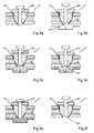
Nachfolgend werden das Gießventil und das Arbeitsverfahren zum Betreiben des Gießventils in einer Gießvorrichtung anhand von Zeichnungen näher beschrieben. Die einzelnen Figuren zeigen:
- Figur 1
- einen Teil einer erfindungsgemäßen Gießvorrichtung mit einer Gießkammer und einem Gießventil im Längsschnitt in schematischer Darstellung,
Figur 2- einen Längsschnitt eines erfindungsgemäßen Gießventils mit zwei konzentrischen Kolben sowie
- Figur 3a
- das erfindungsgemäße Verfahren zum Betreiben des Gießventils durch eine schematischen Darstellung der Stellung des Ventilkolbens zum Zeitpunkt der Reinigung der Gussteilformkavität,
- Figur 3b
- eine schematische Darstellung der Stellung des Ventilkolbens vor dem Gießvorgang,
- Figur 3c
- eine schematische Darstellung der Stellung des Ventilkolbens während des Gießens,
- Figur 3d
- eine schematische Darstellung der Stellung des Ventilkolbens nach Formfüllende,
- Figur 3e
- eine schematische Darstellung der Stellung des Ventilkolbens während des Abkühlens und
- Figur 3f
- eine schematische Darstellung der Stellung des Ventilkolbens unmittelbar vor der Gussteilentnahme.
- FIG. 1
- a part of a casting device according to the invention with a casting chamber and a pouring valve in longitudinal section in a schematic representation,
- FIG. 2
- a longitudinal section of a pouring valve according to the invention with two concentric pistons and
- FIG. 3a
- the method according to the invention for operating the pouring valve by a schematic representation of the position of the valve piston at the time of cleaning the casting mold cavity,
- FIG. 3b
- a schematic representation of the position of the valve piston before the casting process,
- Figure 3c
- a schematic representation of the position of the valve piston during casting,
- 3d figure
- a schematic representation of the position of the valve piston after Formfüllende,
- FIG. 3e
- a schematic representation of the position of the valve piston during cooling and
- FIG. 3f
- a schematic representation of the position of the valve piston immediately before the casting removal.
Der Schmelzekanal 11 ist mit Heizmitteln 5 in Form von Spulen umgeben, die ein Auskühlen der Schmelze 2 verhindern. Vom beheizten Schmelzekanal 11 gelangt die Schmelze 2 über einen Schmelzekanalanschluss 12 in die Ventilzelle 8 (
Angetrieben wird der Ventilkolben 14 durch einen ersten Kolbenantrieb 24, der hydraulisch arbeitet und axial versetzt zum Ventilkolben 14 angeordnet ist. Da der Ventilkolben 14 mit der heißen Schmelze 2 in Kontakt steht, sind Entkopplungsmittel 26 in Form von Zwischenbolzen als Abstandshalter vorgesehen, die den Kolbenantrieb 24 mit der Kolbenplatte 28 vom Kolbenkopf 29 des Ventilkolbens 14 mechanisch und damit auch thermisch entkoppeln, die Druckkraft aber auf den Kolbenkopf 29 dennoch übertragen.The
Der Ventilkolben 14 ist als Hohlzylinder ausgebildet und weist koaxial zur Verschieberichtung einen Nachverdichtungskolben 23 auf. In gleicher Weise wie der Ventilkolben 14 weist der Nachverdichtungskolben 23 einen zweiten Kolbenantrieb 25 auf, der unabhängig vom ersten Kolbenantrieb 24 betreibbar ist. Dessen Hydraulikkammern 30 schließen sich axial an die des ersten Kolbenantriebs 24 an.The
Der Betrieb des in den
Vor dem nächsten Gießvorgang wird die Gussteilkavität 3 so fest verschlossen, dass sie dem Schmelzedruck des anschließenden Druckgießprozesses standhält. Der innere Nachverdichtungskolben 23 fährt in dieser zweiten Phase in seine Ausgangsstellung zurück, die gegenüber dem den Ventilauslass 10 verschließenden Ventilkolben 14 so weit zurückgesetzt ist, dass zwischen den Innenwänden des Ventilkolbens 14 ein Sackloch 27 entsteht. Die Sacklochtiefe entspricht in etwa dem Hub des Ventilkolbens 14.Before the next casting process, the
Durch Zurückziehen des Ventilkolbens 14 wird der eigentliche Gießprozess als dritte Phase eingeleitet. Der Ventilkolben 14 löst sich von seinem ringlinienförmigen Ventilsitz, und durch die nun einströmende, heiße Schmelze 2 wird eventuell an dieser Stelle erkaltetes Material aufgeschmolzen. Aufgrund des Ringlinienkontakts und einer eventuell am Gießventil 7 befindlichen Heizung ist die erstarrte Schmelzemenge so gering, dass sie vollständig aufgeschmolzen wird und ein Öffnen des Ventilkolbens 14 nicht oder nur unwesentlich erschwert. Der Ventilauslass 10 wird maximal geöffnet, und die Schmelze 2 kann ringförmig zwischen den Kolben 14, 23 und der Innenwand 21 des Ventilgehäuses 13 in die Gussteilkavität 3 strömen. Die zum Befüllen vorgesehene Schmelzemenge wird durch den vorfahrenden Gießkolben 6 über den Schmelzekanal 11 nachgeschoben.By retracting the
Nach Abschluss des Formfüllvorgangs werden die Gießventile 7, von denen in
In der fünften Abkühlungsphase erstarrt das Gussstück, und die Gießkammer 4 wird für einen neuen Formfüllvorgang vorbereitet. Während des Erkaltens wird die dadurch bedingte Materialschrumpfung ausgeglichen, indem der Nachverdichtungskolben 23 die sich in dem Sackloch 27 und dem daran unmittelbar anschließenden Bereich befindliche Schmelze 2 in die Gussteilkavität presst. Wenn die Menge der für die Nachverdichtung benötigten Schmelze 2 dem Sacklochvolumen entspricht, kann der an den Ventilauslass 10 anschließende Angusskanal besonders kurz ausfallen oder gegebenenfalls sogar entfallen. Wie in
Vor der Öffnung der Gussteilkavität 3 und der Entnahme des Gussteils erfolgt in der letzten Phase (
- 11
- Gießvorrichtungcaster
- 22
- Schmelzemelt
- 33
- GussteilkavitätGussteilkavität
- 44
- Gießkammercasting chamber
- 55
- Heizmittelheating
- 66
- Gießkolbencasting plunger
- 77
- Gießventilcasting valve
- 88th
- Ventilzellevalve cell
- 99
- Trennflächeinterface
- 1010
- Ventilauslassvalve outlet
- 1111
- Schmelzekanalmelt channel
- 1212
- SchmelzekanalanschlussMelt channel connection
- 1313
- Ventilgehäusevalve housing
- 1414
- Ventilkolbenplunger
- 1515
- GussformhalbschaleMold half shell
- 1616
- GussformhalbschaleMold half shell
- 1717
- Stirnseitefront
- 1818
- Mantelflächelateral surface
- 1919
- Schmelzeventilmelt valve
- 2020
- Zylinderabschnittcylinder section
- 2121
- Innenwandinner wall
- 2222
- VentilhauptachseValve main axis
- 2323
- NachverdichtungskolbenNachverdichtungskolben
- 2424
- erster Kolbenantriebfirst piston drive
- 2525
- zweiter Kolbenantriebsecond piston drive
- 2626
- Entkopplungsmitteldecoupling means
- 2727
- Sacklochblind
- 2828
- Kolbenplattepiston plate
- 2929
- Kolbenkopfpiston head
- 3030
- Hydraulikkammerhydraulic chamber
Claims (10)
dadurch gekennzeichnet, dass
characterized in that
Applications Claiming Priority (1)
| Application Number | Priority Date | Filing Date | Title |
|---|---|---|---|
| DE102013105435.8A DE102013105435B3 (en) | 2013-05-27 | 2013-05-27 | Casting valve with a recompression piston |
Publications (2)
| Publication Number | Publication Date |
|---|---|
| EP2808104A1 true EP2808104A1 (en) | 2014-12-03 |
| EP2808104B1 EP2808104B1 (en) | 2016-11-23 |
Family
ID=50679946
Family Applications (1)
| Application Number | Title | Priority Date | Filing Date |
|---|---|---|---|
| EP14167787.2A Active EP2808104B1 (en) | 2013-05-27 | 2014-05-09 | Casting valve with a final compression piston |
Country Status (5)
| Country | Link |
|---|---|
| US (2) | US9457400B2 (en) |
| EP (1) | EP2808104B1 (en) |
| CN (1) | CN104308115B (en) |
| DE (1) | DE102013105435B3 (en) |
| ES (1) | ES2609381T3 (en) |
Families Citing this family (7)
| Publication number | Priority date | Publication date | Assignee | Title |
|---|---|---|---|---|
| DE102013105433B3 (en) | 2013-05-27 | 2014-05-22 | Schuler Pressen Gmbh | Casting device with a loop and casting process |
| DE102013105435B3 (en) * | 2013-05-27 | 2014-07-10 | Schuler Pressen Gmbh | Casting valve with a recompression piston |
| DE102014205388A1 (en) * | 2014-03-24 | 2015-09-24 | Bayerische Motoren Werke Aktiengesellschaft | Device for die casting a metallic component |
| DE102014111032B3 (en) | 2014-08-04 | 2015-10-01 | Schuler Pressen Gmbh | Casting valve and pouring device |
| JP6455840B2 (en) * | 2015-09-07 | 2019-01-23 | 株式会社アルテックス | Squeeze pin operation determination device and squeeze pin operation determination method |
| JP7254619B2 (en) * | 2019-05-17 | 2023-04-10 | 芝浦機械株式会社 | die casting machine |
| CN114030143B (en) * | 2021-11-17 | 2022-07-22 | 徐州云泰精密技术有限公司 | Collecting ring water gap punching device |
Citations (5)
| Publication number | Priority date | Publication date | Assignee | Title |
|---|---|---|---|---|
| DE3427940A1 (en) | 1984-07-28 | 1986-02-06 | Friedhelm Prof.Dr.-Ing. 6332 Ehringshausen Kahn | Method and apparatuses for controlling the filling of a space by metal melts with the aid of electromagnetic fields |
| DE19508867A1 (en) * | 1994-06-01 | 1995-12-07 | Buehler Ag | Pressure diecasting machine |
| DE19533447C1 (en) * | 1995-09-09 | 1996-12-05 | Bbs Kraftfahrzeugtechnik | Method for filling die with metal melt |
| DE102007047545A1 (en) | 2007-09-29 | 2009-04-02 | Eglass Production & Trade Gmbh | Device for dosing and supplying low-viscous melts such as glass melts, comprises a dosing cell with a reception chamber, a dosing piston arranged within the reception chamber for altering outgoing mass-flow of the melt, and a piping system |
| DE102011050149A1 (en) | 2010-11-17 | 2012-05-24 | Ferrofacta Gmbh | Die casting nozzle and die casting process |
Family Cites Families (13)
| Publication number | Priority date | Publication date | Assignee | Title |
|---|---|---|---|---|
| DE1847509U (en) * | 1961-09-12 | 1962-03-01 | Odenwaelder Kunststoffwerk Dr | SLIDING NOZZLE WITH NEEDLE CONNECTOR FOR INJECTION MOLDING MACHINES. |
| US3960201A (en) * | 1974-12-13 | 1976-06-01 | Societe De Vente De L'aluminium Pechiney | Injection device for molding machines |
| JP2504099B2 (en) * | 1987-02-28 | 1996-06-05 | 日本電装株式会社 | Die casting method and die casting apparatus |
| US4860818A (en) * | 1987-09-21 | 1989-08-29 | Ube Industries, Ltd. | Die casting apparatus |
| JP3477124B2 (en) * | 1999-10-21 | 2003-12-10 | 株式会社日本製鋼所 | Method of applying release agent in metal injection molding machine and metal injection mold |
| DE10001088A1 (en) * | 2000-01-13 | 2001-07-19 | Bayerische Motoren Werke Ag | Die casting tool comprises a casting runner which can be interrupted by a sliding valve |
| DE10305756A1 (en) * | 2003-02-11 | 2004-08-19 | Günther Gmbh & Co., Metallverarbeitung | Concentric feed needle for injection molding with gas blowing includes annular seal in polymer duct to give deep needle penetration into mold space |
| DE20302845U1 (en) * | 2003-02-20 | 2003-05-22 | Guenther Gmbh & Co | needle valve nozzle |
| ATE355145T1 (en) * | 2003-10-15 | 2006-03-15 | Fondarex Sa | PRINTING OR INJECTION MOLDING MACHINE |
| DE102006049073A1 (en) * | 2006-10-13 | 2008-04-17 | Hasco Hasenclever Gmbh + Co Kg | Injection nozzle for guiding melt mass in a plastic injection mold |
| DE102009057197B3 (en) * | 2009-11-30 | 2011-05-19 | Oskar Frech Gmbh + Co. Kg | Casting unit for a die casting machine |
| JP5120429B2 (en) * | 2010-08-24 | 2013-01-16 | 株式会社デンソー | Vacuum die casting equipment |
| DE102013105435B3 (en) * | 2013-05-27 | 2014-07-10 | Schuler Pressen Gmbh | Casting valve with a recompression piston |
-
2013
- 2013-05-27 DE DE102013105435.8A patent/DE102013105435B3/en not_active Expired - Fee Related
-
2014
- 2014-04-21 CN CN201410160136.9A patent/CN104308115B/en active Active
- 2014-05-09 ES ES14167787.2T patent/ES2609381T3/en active Active
- 2014-05-09 EP EP14167787.2A patent/EP2808104B1/en active Active
- 2014-05-19 US US14/280,679 patent/US9457400B2/en active Active
-
2016
- 2016-01-21 US US15/002,406 patent/US9643245B2/en active Active
Patent Citations (5)
| Publication number | Priority date | Publication date | Assignee | Title |
|---|---|---|---|---|
| DE3427940A1 (en) | 1984-07-28 | 1986-02-06 | Friedhelm Prof.Dr.-Ing. 6332 Ehringshausen Kahn | Method and apparatuses for controlling the filling of a space by metal melts with the aid of electromagnetic fields |
| DE19508867A1 (en) * | 1994-06-01 | 1995-12-07 | Buehler Ag | Pressure diecasting machine |
| DE19533447C1 (en) * | 1995-09-09 | 1996-12-05 | Bbs Kraftfahrzeugtechnik | Method for filling die with metal melt |
| DE102007047545A1 (en) | 2007-09-29 | 2009-04-02 | Eglass Production & Trade Gmbh | Device for dosing and supplying low-viscous melts such as glass melts, comprises a dosing cell with a reception chamber, a dosing piston arranged within the reception chamber for altering outgoing mass-flow of the melt, and a piping system |
| DE102011050149A1 (en) | 2010-11-17 | 2012-05-24 | Ferrofacta Gmbh | Die casting nozzle and die casting process |
Also Published As
| Publication number | Publication date |
|---|---|
| CN104308115B (en) | 2018-11-09 |
| DE102013105435B3 (en) | 2014-07-10 |
| US9643245B2 (en) | 2017-05-09 |
| US9457400B2 (en) | 2016-10-04 |
| CN104308115A (en) | 2015-01-28 |
| EP2808104B1 (en) | 2016-11-23 |
| US20140345824A1 (en) | 2014-11-27 |
| US20160129500A1 (en) | 2016-05-12 |
| ES2609381T3 (en) | 2017-04-20 |
Similar Documents
| Publication | Publication Date | Title |
|---|---|---|
| EP2808104B1 (en) | Casting valve with a final compression piston | |
| EP1201335B1 (en) | Device for producing pressure die castings, especially from non-ferrous metals | |
| DE19717381B4 (en) | Injection valve with head and neck area | |
| DE69916775T2 (en) | Actuating mechanism for a valve part of an injection molding device | |
| EP0781640B1 (en) | Heated needle valve nozzle | |
| DE3926357A1 (en) | INJECTION MOLDING DEVICE WITH A NEEDLE CLOSURE | |
| EP2295172B1 (en) | Sprue block unit, sprue system and control unit for a diecast machine | |
| DE2753157A1 (en) | DIE CASTING MACHINE | |
| DE60209505T3 (en) | METHOD FOR INJECTION MOLDING | |
| AT512229B1 (en) | DEVICE, APPARATUS AND METHOD FOR THE PRESSURE GASING OF METALLIC MATERIAL IN THE THIXOTROPIC CONDITION | |
| DE4137664B4 (en) | Injection molding with a separate heating element in the mold cavity forming insert | |
| DE7532061U (en) | DEVICE FOR MECHANIZED LOW PRESSURE CASTING | |
| DE69812502T2 (en) | Casting chamber for a die casting machine and a method for removing impurities | |
| DE4137720A1 (en) | INJECTION MOLDING NOZZLE WITH CONICAL HEATING ELEMENT NEAR THE HOLE | |
| EP3308933A1 (en) | Tube head and device and method for manufacturing a tube head | |
| EP2145747B1 (en) | Molding device and method for producing hollow objects with a projectile formed during the molding process | |
| WO2015155170A1 (en) | Die-casting machine and die-casting process for producing a plurality of castings | |
| EP3423215B1 (en) | Diecasting die system | |
| EP3697554A1 (en) | Die casting mold for casting cylinder crankcases or crankcase subparts | |
| DE102014111032B3 (en) | Casting valve and pouring device | |
| AT517860B1 (en) | Method and device for producing at least one molded part | |
| EP3790689B1 (en) | Module for a die-casting device | |
| EP3122494B1 (en) | Device for die casting a metal component | |
| DE102012203039B4 (en) | Method for operating a die-casting machine with a melt transport device | |
| AT519391A1 (en) | Mold divider for installation in a mold |
Legal Events
| Date | Code | Title | Description |
|---|---|---|---|
| PUAI | Public reference made under article 153(3) epc to a published international application that has entered the european phase |
Free format text: ORIGINAL CODE: 0009012 |
|
| 17P | Request for examination filed |
Effective date: 20140509 |
|
| AK | Designated contracting states |
Kind code of ref document: A1 Designated state(s): AL AT BE BG CH CY CZ DE DK EE ES FI FR GB GR HR HU IE IS IT LI LT LU LV MC MK MT NL NO PL PT RO RS SE SI SK SM TR |
|
| AX | Request for extension of the european patent |
Extension state: BA ME |
|
| R17P | Request for examination filed (corrected) |
Effective date: 20141208 |
|
| RBV | Designated contracting states (corrected) |
Designated state(s): AL AT BE BG CH CY CZ DE DK EE ES FI FR GB GR HR HU IE IS IT LI LT LU LV MC MK MT NL NO PL PT RO RS SE SI SK SM TR |
|
| GRAP | Despatch of communication of intention to grant a patent |
Free format text: ORIGINAL CODE: EPIDOSNIGR1 |
|
| RIC1 | Information provided on ipc code assigned before grant |
Ipc: B22D 27/11 20060101ALI20160603BHEP Ipc: B22D 17/20 20060101AFI20160603BHEP Ipc: B22D 17/30 20060101ALI20160603BHEP |
|
| INTG | Intention to grant announced |
Effective date: 20160622 |
|
| GRAS | Grant fee paid |
Free format text: ORIGINAL CODE: EPIDOSNIGR3 |
|
| GRAA | (expected) grant |
Free format text: ORIGINAL CODE: 0009210 |
|
| AK | Designated contracting states |
Kind code of ref document: B1 Designated state(s): AL AT BE BG CH CY CZ DE DK EE ES FI FR GB GR HR HU IE IS IT LI LT LU LV MC MK MT NL NO PL PT RO RS SE SI SK SM TR |
|
| REG | Reference to a national code |
Ref country code: GB Ref legal event code: FG4D Free format text: NOT ENGLISH |
|
| REG | Reference to a national code |
Ref country code: CH Ref legal event code: EP |
|
| REG | Reference to a national code |
Ref country code: IE Ref legal event code: FG4D Free format text: LANGUAGE OF EP DOCUMENT: GERMAN |
|
| REG | Reference to a national code |
Ref country code: AT Ref legal event code: REF Ref document number: 847407 Country of ref document: AT Kind code of ref document: T Effective date: 20161215 |
|
| REG | Reference to a national code |
Ref country code: DE Ref legal event code: R096 Ref document number: 502014002021 Country of ref document: DE |
|
| REG | Reference to a national code |
Ref country code: DE Ref legal event code: R096 Ref document number: 502014002021 Country of ref document: DE |
|
| PG25 | Lapsed in a contracting state [announced via postgrant information from national office to epo] |
Ref country code: LV Free format text: LAPSE BECAUSE OF FAILURE TO SUBMIT A TRANSLATION OF THE DESCRIPTION OR TO PAY THE FEE WITHIN THE PRESCRIBED TIME-LIMIT Effective date: 20161123 |
|
| REG | Reference to a national code |
Ref country code: LT Ref legal event code: MG4D |
|
| REG | Reference to a national code |
Ref country code: NL Ref legal event code: MP Effective date: 20161123 |
|
| REG | Reference to a national code |
Ref country code: ES Ref legal event code: FG2A Ref document number: 2609381 Country of ref document: ES Kind code of ref document: T3 Effective date: 20170420 |
|
| PG25 | Lapsed in a contracting state [announced via postgrant information from national office to epo] |
Ref country code: SE Free format text: LAPSE BECAUSE OF FAILURE TO SUBMIT A TRANSLATION OF THE DESCRIPTION OR TO PAY THE FEE WITHIN THE PRESCRIBED TIME-LIMIT Effective date: 20161123 Ref country code: GR Free format text: LAPSE BECAUSE OF FAILURE TO SUBMIT A TRANSLATION OF THE DESCRIPTION OR TO PAY THE FEE WITHIN THE PRESCRIBED TIME-LIMIT Effective date: 20170224 Ref country code: LT Free format text: LAPSE BECAUSE OF FAILURE TO SUBMIT A TRANSLATION OF THE DESCRIPTION OR TO PAY THE FEE WITHIN THE PRESCRIBED TIME-LIMIT Effective date: 20161123 Ref country code: NL Free format text: LAPSE BECAUSE OF FAILURE TO SUBMIT A TRANSLATION OF THE DESCRIPTION OR TO PAY THE FEE WITHIN THE PRESCRIBED TIME-LIMIT Effective date: 20161123 Ref country code: NO Free format text: LAPSE BECAUSE OF FAILURE TO SUBMIT A TRANSLATION OF THE DESCRIPTION OR TO PAY THE FEE WITHIN THE PRESCRIBED TIME-LIMIT Effective date: 20170223 |
|
| REG | Reference to a national code |
Ref country code: FR Ref legal event code: PLFP Year of fee payment: 4 |
|
| PG25 | Lapsed in a contracting state [announced via postgrant information from national office to epo] |
Ref country code: PL Free format text: LAPSE BECAUSE OF FAILURE TO SUBMIT A TRANSLATION OF THE DESCRIPTION OR TO PAY THE FEE WITHIN THE PRESCRIBED TIME-LIMIT Effective date: 20161123 Ref country code: PT Free format text: LAPSE BECAUSE OF FAILURE TO SUBMIT A TRANSLATION OF THE DESCRIPTION OR TO PAY THE FEE WITHIN THE PRESCRIBED TIME-LIMIT Effective date: 20170323 Ref country code: FI Free format text: LAPSE BECAUSE OF FAILURE TO SUBMIT A TRANSLATION OF THE DESCRIPTION OR TO PAY THE FEE WITHIN THE PRESCRIBED TIME-LIMIT Effective date: 20161123 Ref country code: HR Free format text: LAPSE BECAUSE OF FAILURE TO SUBMIT A TRANSLATION OF THE DESCRIPTION OR TO PAY THE FEE WITHIN THE PRESCRIBED TIME-LIMIT Effective date: 20161123 Ref country code: RS Free format text: LAPSE BECAUSE OF FAILURE TO SUBMIT A TRANSLATION OF THE DESCRIPTION OR TO PAY THE FEE WITHIN THE PRESCRIBED TIME-LIMIT Effective date: 20161123 |
|
| PG25 | Lapsed in a contracting state [announced via postgrant information from national office to epo] |
Ref country code: EE Free format text: LAPSE BECAUSE OF FAILURE TO SUBMIT A TRANSLATION OF THE DESCRIPTION OR TO PAY THE FEE WITHIN THE PRESCRIBED TIME-LIMIT Effective date: 20161123 Ref country code: SK Free format text: LAPSE BECAUSE OF FAILURE TO SUBMIT A TRANSLATION OF THE DESCRIPTION OR TO PAY THE FEE WITHIN THE PRESCRIBED TIME-LIMIT Effective date: 20161123 Ref country code: DK Free format text: LAPSE BECAUSE OF FAILURE TO SUBMIT A TRANSLATION OF THE DESCRIPTION OR TO PAY THE FEE WITHIN THE PRESCRIBED TIME-LIMIT Effective date: 20161123 Ref country code: RO Free format text: LAPSE BECAUSE OF FAILURE TO SUBMIT A TRANSLATION OF THE DESCRIPTION OR TO PAY THE FEE WITHIN THE PRESCRIBED TIME-LIMIT Effective date: 20161123 Ref country code: CZ Free format text: LAPSE BECAUSE OF FAILURE TO SUBMIT A TRANSLATION OF THE DESCRIPTION OR TO PAY THE FEE WITHIN THE PRESCRIBED TIME-LIMIT Effective date: 20161123 |
|
| REG | Reference to a national code |
Ref country code: DE Ref legal event code: R097 Ref document number: 502014002021 Country of ref document: DE |
|
| PG25 | Lapsed in a contracting state [announced via postgrant information from national office to epo] |
Ref country code: LU Free format text: LAPSE BECAUSE OF NON-PAYMENT OF DUE FEES Effective date: 20170531 Ref country code: BG Free format text: LAPSE BECAUSE OF FAILURE TO SUBMIT A TRANSLATION OF THE DESCRIPTION OR TO PAY THE FEE WITHIN THE PRESCRIBED TIME-LIMIT Effective date: 20170223 Ref country code: SM Free format text: LAPSE BECAUSE OF FAILURE TO SUBMIT A TRANSLATION OF THE DESCRIPTION OR TO PAY THE FEE WITHIN THE PRESCRIBED TIME-LIMIT Effective date: 20161123 |
|
| PLBE | No opposition filed within time limit |
Free format text: ORIGINAL CODE: 0009261 |
|
| STAA | Information on the status of an ep patent application or granted ep patent |
Free format text: STATUS: NO OPPOSITION FILED WITHIN TIME LIMIT |
|
| 26N | No opposition filed |
Effective date: 20170824 |
|
| PG25 | Lapsed in a contracting state [announced via postgrant information from national office to epo] |
Ref country code: SI Free format text: LAPSE BECAUSE OF FAILURE TO SUBMIT A TRANSLATION OF THE DESCRIPTION OR TO PAY THE FEE WITHIN THE PRESCRIBED TIME-LIMIT Effective date: 20161123 |
|
| PG25 | Lapsed in a contracting state [announced via postgrant information from national office to epo] |
Ref country code: MC Free format text: LAPSE BECAUSE OF FAILURE TO SUBMIT A TRANSLATION OF THE DESCRIPTION OR TO PAY THE FEE WITHIN THE PRESCRIBED TIME-LIMIT Effective date: 20161123 |
|
| REG | Reference to a national code |
Ref country code: IE Ref legal event code: MM4A |
|
| PG25 | Lapsed in a contracting state [announced via postgrant information from national office to epo] |
Ref country code: LU Free format text: LAPSE BECAUSE OF NON-PAYMENT OF DUE FEES Effective date: 20170509 |
|
| REG | Reference to a national code |
Ref country code: BE Ref legal event code: MM Effective date: 20170531 |
|
| PG25 | Lapsed in a contracting state [announced via postgrant information from national office to epo] |
Ref country code: IE Free format text: LAPSE BECAUSE OF NON-PAYMENT OF DUE FEES Effective date: 20170509 |
|
| REG | Reference to a national code |
Ref country code: FR Ref legal event code: PLFP Year of fee payment: 5 |
|
| PG25 | Lapsed in a contracting state [announced via postgrant information from national office to epo] |
Ref country code: BE Free format text: LAPSE BECAUSE OF NON-PAYMENT OF DUE FEES Effective date: 20170531 |
|
| PG25 | Lapsed in a contracting state [announced via postgrant information from national office to epo] |
Ref country code: MT Free format text: LAPSE BECAUSE OF FAILURE TO SUBMIT A TRANSLATION OF THE DESCRIPTION OR TO PAY THE FEE WITHIN THE PRESCRIBED TIME-LIMIT Effective date: 20161123 |
|
| GBPC | Gb: european patent ceased through non-payment of renewal fee |
Effective date: 20180509 |
|
| PG25 | Lapsed in a contracting state [announced via postgrant information from national office to epo] |
Ref country code: GB Free format text: LAPSE BECAUSE OF NON-PAYMENT OF DUE FEES Effective date: 20180509 |
|
| PG25 | Lapsed in a contracting state [announced via postgrant information from national office to epo] |
Ref country code: HU Free format text: LAPSE BECAUSE OF FAILURE TO SUBMIT A TRANSLATION OF THE DESCRIPTION OR TO PAY THE FEE WITHIN THE PRESCRIBED TIME-LIMIT; INVALID AB INITIO Effective date: 20140509 |
|
| PG25 | Lapsed in a contracting state [announced via postgrant information from national office to epo] |
Ref country code: CY Free format text: LAPSE BECAUSE OF FAILURE TO SUBMIT A TRANSLATION OF THE DESCRIPTION OR TO PAY THE FEE WITHIN THE PRESCRIBED TIME-LIMIT Effective date: 20161123 |
|
| PG25 | Lapsed in a contracting state [announced via postgrant information from national office to epo] |
Ref country code: MK Free format text: LAPSE BECAUSE OF FAILURE TO SUBMIT A TRANSLATION OF THE DESCRIPTION OR TO PAY THE FEE WITHIN THE PRESCRIBED TIME-LIMIT Effective date: 20161123 |
|
| PG25 | Lapsed in a contracting state [announced via postgrant information from national office to epo] |
Ref country code: TR Free format text: LAPSE BECAUSE OF FAILURE TO SUBMIT A TRANSLATION OF THE DESCRIPTION OR TO PAY THE FEE WITHIN THE PRESCRIBED TIME-LIMIT Effective date: 20161123 |
|
| PG25 | Lapsed in a contracting state [announced via postgrant information from national office to epo] |
Ref country code: AL Free format text: LAPSE BECAUSE OF FAILURE TO SUBMIT A TRANSLATION OF THE DESCRIPTION OR TO PAY THE FEE WITHIN THE PRESCRIBED TIME-LIMIT Effective date: 20161123 Ref country code: IS Free format text: LAPSE BECAUSE OF FAILURE TO SUBMIT A TRANSLATION OF THE DESCRIPTION OR TO PAY THE FEE WITHIN THE PRESCRIBED TIME-LIMIT Effective date: 20170323 |
|
| P01 | Opt-out of the competence of the unified patent court (upc) registered |
Effective date: 20230524 |
|
| PGFP | Annual fee paid to national office [announced via postgrant information from national office to epo] |
Ref country code: IT Payment date: 20230531 Year of fee payment: 10 Ref country code: FR Payment date: 20230517 Year of fee payment: 10 Ref country code: ES Payment date: 20230621 Year of fee payment: 10 Ref country code: DE Payment date: 20230421 Year of fee payment: 10 Ref country code: CH Payment date: 20230605 Year of fee payment: 10 |
|
| PGFP | Annual fee paid to national office [announced via postgrant information from national office to epo] |
Ref country code: AT Payment date: 20230516 Year of fee payment: 10 |