EP2807442B1 - Kommunikation und steuerung von an der stromschiene einer waffe montiertem zubehör - Google Patents
Kommunikation und steuerung von an der stromschiene einer waffe montiertem zubehör Download PDFInfo
- Publication number
- EP2807442B1 EP2807442B1 EP12866566.8A EP12866566A EP2807442B1 EP 2807442 B1 EP2807442 B1 EP 2807442B1 EP 12866566 A EP12866566 A EP 12866566A EP 2807442 B1 EP2807442 B1 EP 2807442B1
- Authority
- EP
- European Patent Office
- Prior art keywords
- power
- accessory
- consuming
- weapon
- powered
- Prior art date
- Legal status (The legal status is an assumption and is not a legal conclusion. Google has not performed a legal analysis and makes no representation as to the accuracy of the status listed.)
- Not-in-force
Links
Images




Classifications
-
- F—MECHANICAL ENGINEERING; LIGHTING; HEATING; WEAPONS; BLASTING
- F41—WEAPONS
- F41C—SMALLARMS, e.g. PISTOLS, RIFLES; ACCESSORIES THEREFOR
- F41C23/00—Butts; Butt plates; Stocks
- F41C23/22—Stocks having space for the storage of objects
-
- F—MECHANICAL ENGINEERING; LIGHTING; HEATING; WEAPONS; BLASTING
- F41—WEAPONS
- F41G—WEAPON SIGHTS; AIMING
- F41G11/00—Details of sighting or aiming apparatus; Accessories
- F41G11/001—Means for mounting tubular or beam shaped sighting or aiming devices on firearms
- F41G11/003—Mountings with a dove tail element, e.g. "Picatinny rail systems"
Definitions
- the invention relates to a communications and control system for use with a Powered Rail of a weapon to provide communications and control signals as well as electric power to power-consuming accessories mounted on the Powered Rail.
- a weapon used in military applications may have a plurality of accessories that can be attached to the weapon, with each accessory having a need for electric power.
- a common power source is used to power whatever power-consuming accessory is attached to the weapon.
- a Powered Rail provides a point of mechanical and electrical interconnection for the power-consuming accessories to provide quick connect mounting and dismounting of the power-consuming accessory, absent the use of connectors with their tethering cables, which are susceptible to entanglement.
- a Powered Rail by itself fails to provide a user with control over the operation of the power-consuming accessories, since it simply provides an electrical connection to the power source and must rely on a power switch mounted on each power-consuming accessory to enable the user to apply power in a binary, on/off manner to that power-consuming accessory.
- the need to operate such a switch on a power-consuming accessory is inconvenient and prevents the user from having the ability to rapidly power-up and power-down the power-consuming accessory.
- a power control method is cumbersome at best.
- US 2011/173865 A1 and US 2010/192444 disclose a weapon accessory control system for use with a Powered Rail that extends along at least a portion of a length of a barrel of a weapon for providing a source of electrical power to at least one power-consuming accessory that is mechanically and electrically attached to the Powered Rail, the weapon accessory control system comprising:
- the above-described problems are solved and a technical advance achieved by the subject matter of independent system claim 1 and of independent method claim 9.
- the Powered Rail is electrically interconnected with a power source, and the Weapon Accessory Control System is provided to enable the user to control the activation of a power-consuming accessory from a centrally located control interface.
- the control and communication architecture enables communications not only between the user and the power-consuming accessories but also among power-consuming accessories, independent of the presence of a centrally located control apparatus.
- Powered Rail on a weapon serves multiple types of power-consuming accessories such as: tactical lights, laser aiming modules, night vision devices, and reflex sights.
- the Powered Rail can be incorporated on the top, bottom, or sides of the rifle barrel, the underside of semi-automatic pistol frames, and even on weapon grips. Regardless of the location and implementation of the Powered Rail, the problem of control and communication with and among the power-consuming accessories is a universal issue.
- FIGS 1A and 1B are illustrations of the system architecture of a military style weapon 2 equipped with a Weapon Accessory Power Distribution System.
- the primary components of the basic Weapon Accessory Power Distribution System are:
- the existing military-style weapon 2 includes in well-known fashion an upper receiver 101, lower receiver 102, barrel 103, muzzle 104, grip 105, and front sight 106. While a military-style weapon is described herein, the teachings of this application are equally applicable to other firearms, such as handguns, fixed-mount machine guns, as well as non-weapon based systems, such as air-soft (paint ball) systems.
- the Weapon Accessory Power Distribution System is added to this standard military-style weapon 2 as described herein.
- the Handguard 23 performs the barrel shielding function as in the Picatinny Rail noted above, but has been modified, as shown in Figures 1A and 1B , to accommodate the Powered Rail 24 and electrical interconnection of the Powered Accessory Mounting 25 to the Powered Rail 24, as described below.
- a combination of Powered Rails 24 and Handguard sections 23 are attached together to form a structure which encircles the barrel 103.
- the Powered Rail 24 in effect forms facets around the periphery of the resultant Handguard structure.
- the term "Handguard” is used to represent the sections of handguard structure as well as the well-known combination of Handguard sections and Powered Rails which encircle the barrel 103 as shown in Figures 1A and 1B .
- the Powered Rail 24 can be attached to a Handguard 23 that encircles the barrel. Furthermore, there is no requirement to use the Handguard 23 as an integral component of the Weapon Accessory Power Distribution System, so the Handguard 23 can be optional, with the Powered Rail(s) 24 being attached to the weapon in some other manner, such as an upper receiver rail 101 in Figure 1A .
- the first of the above-listed configurations is used herein.
- the Handguard 23 was developed to shroud the barrel 103 of a rapid fire weapon 2 to enable the person firing the weapon 2 to grip the forward portion of the weapon 2 while mitigating the possibility of burning the hand of the person firing the weapon 2, yet also providing adequate cooling for the barrel 103 of the weapon.
- Handguards find application in rifles, carbines, and fixed mount weapons, such as machine guns.
- the Weapon Accessory Control System can also be used in modified form for handguns, as an accessory mounting platform and as an accessory power source.
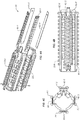
- FIGS 4A - 4C are perspective exploded view, side view, and end view illustrations, respectively, of the Handguard 23 assembly, including the Powered Rail 24, of the Weapon Accessory Control System.
- This version of the Handguard 23 includes one or more power distribution Printed Circuit Boards 60-1 to 60-4, with Figure 5C showing an end view of the slots formed in the various facets F1-F4 of the Handguard 23.
- Apertures A are provided along the length dimension L of the Handguard 23 to enable the barrel 103 of the weapon 2 to be cooled by air circulation from the ambient environment.
- Other Powered Rail configurations are possible, and this architecture is provided as an illustration of the concepts of the Weapon Accessory Power Distribution System.
- One or more of the Powered Rail subassemblies (typically Printed Circuit Boards) 60-1 to 60-4 can be inserted into the respective slots formed in the Powered Rail 24 (on the corresponding facets F1-F4 of the Handguard 23) thereby to enable power-consuming accessories to be attached to the Handguard 23 of the weapon 2 via the Powered Rail 24 on any facet F1-F4 of the Handguard 23 and to be powered by the corresponding power conductors 62-P and 62-N activated by switch 62-S formed on Printed Circuit Board 60-1 to 60-4 which are installed in the Powered Rail 24 on the respective facets.
- the Powered Rail subassemblies typically Printed Circuit Boards
- the Battery Pack can be implemented in a number of assemblies and mounted on various portions of the weapon (such as on the Powered Rail, or in a pistol grip, or in a remote power source, and the like) as described in US Patent Application Serial No. 12/689,438 filed on January 19, 2010 , titled "Rifle Accessory Rail, Communication, And Power Transfer System - Battery Pack.”
- Figures 2A and 2B are illustrations of a typical Butt Stock 21 with Battery Pack 33 of the Weapon Accessory Control System.
- a butt stock/recoil tube battery pack assembly includes an adjustable butt stock 21, a cam latch 32, and a removable battery pack 33.
- the butt stock 21 adds a compartment to the underside of the existing lower receiver extension (also termed “buffer tube” herein) assembly 34 which allows the battery pack 33 to be installed and withdrawn for removal through the rear of the rifle.
- the battery pack 33 mounts on the buffer tube assembly 34 independent of the butt stock 21 which telescopes along the rifle.
- the butt stock 21 is adjustable and can be extended in various multiple intermediate positions to provide an adjustable length of the firearm, as is well known in the art. By moving the mass of the battery rearward on the weapon, the time required to bring the weapon to point is reduced, as well as the time needed to "stop" the muzzle when the target is acquired.
- the Power Distribution System 22 is shown in Figures 1A, 1B , and 3A - 3C as a one-piece housing 201 and ruggedized power rail connector 202 where sealing integrity is maintained during exposure to adverse environmental conditions.
- the power rail connector 202 consists of a metallic shell body, contact pin receptacle 203, with a press fit multi-finger spring contact 204 assembled into the contact pin receptacle 203.
- the multi-finger spring contact 204 provides compliance to variations in the mating pin to ensure continuous current carrying capacity of the connection.
- the contact pin receptacle 203 includes a solder tail portion for soldering cable wires.
- the bottom panel insulator 205 mounts the pin receptacle 203 with the bottom part and fitted over the connector contact pin receptacle 203 and is sealed with a sealing compound.
- a fastener 206 and retaining ring 207 are used to secure the connector assembly into the rail pin contacts.
- An electric wire is routed from the Battery Pack 33 in the Butt Stock 21 to the Powered Rail 24.
- the external wiring is housed inside a durable and impact-resistant polymer shroud 108 that conforms to the lower receiver 102.
- the shroud is securely retained by a quick connect/disconnect pivot and takedown pin 111, as well as the bolt release roll pin 109 in the trigger/hammer pins 110.
- the shrouded power cable runs from the Battery Power Connector 107 at the Battery Pack 33 to the Power Rail Connector 202. This design provides an easy access for replacing or repairing the cable assembly, eliminates snag hazards or interferences with the rifle operation, and requires no modifications to the rifle lower receiver 102 housing.
- the Powered Rail 24 is used to electrically interconnect a power source (Battery Pack 33) with the various power-consuming accessories 7, 8 mounted on the Powered Rail 24, such that the Powered Rail 24 of the Handguard 23 provides the mechanical support for the power-consuming accessories 7, 8; and the Powered Rail 24 also provides the electrical interconnection.
- the Powered Rail 24 is attached to and coextensive with the Handguard 23 sections, such that the mounting of a Power-Consuming Accessory 7, 8 on the Powered Rail 24 results in simultaneous mechanical and electrical interconnection.
- Figure 5 is an illustration of the typical mechanical interconnection and electrical interconnection of a power-consuming accessory (such as flashlight 8 or night vision device 7) to the Handguard 23 and Powered Rail 24.
- the perspective view of Figure 5 shows how the Powered Accessory Mounting 25 attaches the power-consuming accessory 8 to the Powered Rail 24 and consists of a rail grabber 301, spring contacts 302, spring plungers 303, and face seals 304.
- the spring plungers 303 depress the snap-dome switches on the Powered Rail 24, the spring contacts 302 provide electrical contact with the fixed electrical bus contacts 62M and 62P-* on the Powered Rail 24 Printed Circuit Board assembly, and the face seals 304 provide environmental protection.
- Figures 6A and 6B illustrate side views of two implementations of a typical user interface 1201 of the Weapon Accessory Control System 1300; and Figure7 illustrates a circuit diagram of a typical weapon that is equipped with the Weapon Accessory Control System 1300 and a plurality of power-consuming accessories 7, 8 and their associated Powered Control Modules 700.
- the Weapon Accessory Control System 1300 consists of a Powered Control Module 700, Powered Accessory Mounting 25, and User Interface 1201, and functions as the Master in a Master-Slave relationship with the power-consuming accessories (Slave), each of which are equipped with control circuits 1311, 1312, each of which includes a Powered Control Module 700, Powered Accessory Mounting 25, and some power-consuming device 701, which is a component of a power-consuming accessory, such as a tactical light 8, laser aiming module, night vision device 7, or reflex sight.
- a Powered Control Module 700 Powered Accessory Mounting 25, and User Interface 1201
- control circuits 1311, 1312 each of which includes a Powered Control Module 700, Powered Accessory Mounting 25, and some power-consuming device 701, which is a component of a power-consuming accessory, such as a tactical light 8, laser aiming module, night vision device 7, or reflex sight.
- the Weapon Accessory Control System User Interface 1201 is shown in both the horizontal (juxtaposed to and substantially parallel to the barrel of the weapon) and vertical grip (extending in a downward direction and substantially perpendicular to the barrel of the weapon) designs in Figures 6A and 6B , respectively.
- the Weapon Accessory Control System 1300 has the ability to pass command and control signals over the Powered Rail 24 in order to activate and de-activate power-consuming accessories 7, 8 which are mounted on the Powered Rail 24, as well as to provide power-consuming accessory identification and status.
- Communications between the control circuits 1312, 1311 contained in the respective power-consuming accessories 7, 8 and the Weapon Accessory Control System 1300 are accomplished by impressing a modulated signal on the power supply conductors 62-P, 62-N of the Powered Rail 24. This reduces the number of conductors required to distribute communications and confines the control signals to the Powered Rail 24 assembly.
- the Battery Pack 33 contains a power source which is interconnected to the Powered Rail 24 as described above, typically through a short-circuit protection circuit 1301.
- Each power-consuming accessory 7, 8, as described above, is mechanically and electrically connected to the Powered Rail 24 via, for example, the Powered Accessory Mounting 25, and includes a Powered Control Module 700 which provides the control and communications circuitry to regulate the provision of power to the associated power-consuming device 701 as well as status and control intercommunications among the power-consuming accessories 7,8 and the Weapon Accessory Control System 1300.
- the Powered Control Module 700 with optional selector switches (not shown) built into the power-consuming accessories 7, 8, enables the unique identification of specific power-consuming accessories 7, 8 and the regulation of power applied to the power-consuming device 701 of the power-consuming accessories 7, 8.
- the associated Powered Control Module 700 in each power-consuming accessories 7, 8 can be programmed to respond to a particular control signal which is unique to power-consuming accessories 7, 8, or can optionally utilize one or more selector switches which assign a user control button identification signal which corresponds to a desired functionality for the designated power-consuming accessories 7, 8.
- the power-consuming accessories 7,8 are plug-and-play in nature in that they can be self-initializing if the Weapon Accessory Control System 1300 is absent or powered down or unable to communicate with the power-consuming accessories 7,8.
- the Weapon Accessory Control System 1300 is typically equipped with a plurality of switches 1211-1214 in the user interface 1201, each of which typically controls a different power-consuming accessory 7, 8 via the use of a predetermined signaling paradigm.
- switches 1211-1214 in the user interface 1201, each of which typically controls a different power-consuming accessory 7, 8 via the use of a predetermined signaling paradigm.
- the user wanted to momentarily power a target illuminator 8, they would hold down switch 1211, which would power the target illuminator 8 via the Powered Control Module 700 resident in target illuminator 8 (part of circuitry 1311) as long as the switch 1211 was operated. If they wanted to maintain power to the target illuminator 8, they would press and release switch 1211. To turn off the target illuminator 8, they would press switch 1211 again.
- different combinations of switches and switch activation sequences could activate functions on any number of power-consuming accessories 7, 8.
- each of switches 1211-1214 would result in a uniquely coded signal being impressed on the Powered Rail 24.
- the Powered Control Module 700 generates the predetermined unique signal (for example, different frequency signals) which is associated with the operated switch 1211. This unique signal is impressed on the Powered Rail 24 via Front End Circuit 802 of the Powered Control Module 700. Since both the power-consuming accessories 7, 8 and the Weapon Accessory Control System 1300 are equipped with respective Powered Control Modules 700, bidirectional communications between the power-consuming accessories 7, 8 and the Weapon Accessory Control System 1300 is possible, as well as between the power-consuming accessories 7,8.
- Weapon Accessory Control System 1300 which implements various functions including, but not limited to:
- the software which executes on Powered Control Module 700 must also be capable of operating reliably in the presence of noise on the Powered Rail 24, via the operation of Loop Filter 808.
- noise is any event that interferes with the successful transmission and reception of a packet, such as the attachment of a new power-consuming accessory 7, 8 to the Powered Rail 24.
- the software which executes in the Powered Control Module 700 must dynamically detect the installation of a new power-consuming accessory 7, 8, and the removal of a power-consuming accessory 7, 8, and adjust accordingly. Communications with power-consuming accessories 7, 8 is provided through a Front-End Circuit 802 which uses a high-speed Serial Peripheral Interface 803 to communicate with Microcontroller 801.
- a Crystal 805 and Tank Circuit 807 are provided to generate the various specific frequency clock signals.
- the Microcontroller 801 does not have an operating system, and the software is interrupt-driven, with a simple dispatching loop.
- the interrupts are received from the associated power-consuming accessory on lead(s) inputs and handled by Interrupt Generator 804.
- Responses, such as Pulse Width Modulation control signals, are returned to the power-consuming accessories 7, 8 via output lead Out.
- the Weapon Accessory Control System 1300 also allows various power-consuming accessories 7, 8, attached to a common Powered Rail 24, to communicate with each other, using the Powered Rail power conductors 62-P, 62-N as a wired connection for low-power signals, typically in the 800+ MHz region of the spectrum.
- the associated communications software is a single module, having multiple software components (as shown in Figure 9 ), that reside on the Memory 806 associated with Microcontroller 801, in various power-consuming accessories 7, 8.
- the role of a specific accessory Powered Control Module 700 changes as a function of the power-consuming accessories 7, 8 on which it executes.
- a Powered Control Module 700 located in a first power-consuming accessory 7 monitors button press events and sends messages to another Powered Control Module 700 located in a second power-consuming accessory 8, commanding the other Powered Control Module 700 to turn a device on or off.
- Powered Control Modules 700 a single executable image is envisioned; the specific role that the image performs is a function of configuration information that is stored within flash memory on the power-consuming accessories 7, 8. Because power-consuming accessories 7, 8 can be attached or removed at any time, software must dynamically detect the installation of new power-consuming accessories 7, 8, and the removal of power-consuming accessories 7, 8, and adjust accordingly.
- the power-consuming accessories 7,8 can communicate among themselves absent the presence of the Weapon Accessory Control System 1300.
- the heart of the Powered Control Module 700 is the Microcontroller 801 which includes a predetermined amount of memory 806 which stores an executable program, tables of data, and variable storage. Communications with other Powered Control Modules 700 are implemented via the Front End Device 802, and the Serial Peripheral Interface 803 enables the Microcontroller 801 and the Front End Circuit to communicate.
- the Serial Peripheral Interface 803 is a synchronous serial data link that operates in full duplex mode. Devices communicate in master/slave mode where the master device initiates the data frame. Multiple slave devices are allowed with individual slave select (chip select) lines.
- the Serial Peripheral Interface 803 specifies four logic signals:
- the Serial Peripheral Interface 803 as shown herein can operate with a single master device and with one or more slave devices. If a single slave device is used, the Slave Select pin may be fixed to logic low if the slave permits it. Some slaves require the falling edge (high ⁇ low transition) of the chip select to initiate an action such as conversion on said transition. With multiple slave devices, an independent Slave Select signal is required from the master for each slave device. Most slave devices have tri-state outputs so their Master Input, Slave Out signal becomes high impedance ("disconnected") when the device is not selected. Devices without tri-state outputs cannot share Serial Peripheral Interface 803 segments with other devices; only one such slave could talk to the master, and only its chip select could be activated.
- the master first configures the clock, using a frequency less than or equal to the maximum frequency the slave device supports. The master then pulls the chip select low for the desired chip. If a waiting period is required (such as for analog-to-digital conversion), then the master must wait for at least that period of time before starting to issue clock cycles.
- Transmissions normally involve two shift registers of some given word size, such as eight bits, one in the master and one in the slave; they are connected in a ring. Data usually are shifted out with the most significant bit first, while shifting a new least significant bit into the same register. After that register has been shifted out, the master and slave have exchanged register values. Each device then takes that value and does something with it, such as writing it to memory. If there are more data to exchange, the shift registers are loaded with new data and the process repeats. Transmissions may involve any number of clock cycles. When there are no more data to be transmitted, the master stops toggling its clock. Normally, it then deselects the slave.
- some given word size such as eight bits
- Transmissions often consist of 8-bit words, and a master can initiate multiple such transmissions if it wishes/needs.
- other word sizes are also common, such as 16-bit words for touchscreen controllers or audio codes; or 12-bit words for many digital-to-analog or analog-to-digital converters.
- Every slave on the bus that hasn't been activated using its chip select line must disregard the input clock and Master Output, Slave Input signals, and must not drive Master Input, Slave Output. The master must select only one slave at a time.
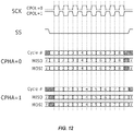
- the master In addition to setting the clock frequency, the master must also configure the clock polarity and phase with respect to the data.
- the timing diagram is shown in Figure 12 . The timing is further described below and applies to both the master and the slave device.
- FIG. 9 illustrates in block diagram form the software architecture of the Powered Control Module 700, such as that resident in Weapon Accessory Control System 1300.
- the Initialization Module 901 runs from power-on or reset. This unit calls the following initialization functions which are stored in PCM Configuration Memory 9011, in the sequence indicated below. Note that specific calls may be skipped based on the device type; for example, a flashlight need not initialize button inputs, and a handgrip need not initialize the Pulse Width Modulation function:
- the Microcontroller 801 services interrupts that are received from the Front End Chip 802, timers, and external discrete signals (e.g., buttons 921 via debounce process 903), as well as the associated power-consuming accessory via lead Input.
- the interrupts result in changes of state within data structures (such as connection tables 9014, button status variables).
- the Main Loop 902 within Microcontroller 801 services input messages (by calling connectPoll) and queued button events. If the Main Loop 902 determines that no activity has occurred, it places the Microcontroller 801 in a low-power (idle) state.
- An interrupt from any of the Serial Peripheral Interface 803 (indicating a message receive), a timer, or a button press, awakens the Microcontroller 801, and the debounce software 903 places an entry in a debounce FIFO as a result of a button press.
- the Main Loop 902 calls the Device Controller software 904, which retrieves translation data from Device Type Table 9012.
- a message process 906 is activated to initiate a connection via Connection Process 907 and Connections Table 9014 (as described in more detail below).
- Microcontroller 801 routes the event by RF Driver process 908 and Serial Peripheral Interface Driver process 909 to output the control signals over the Powered Rail 24 (via Front End Chip 802 and Serial Peripheral Interface 803) to an appropriate power-consuming accessory using the button rules table 9013.
- the connect functions place an entry in the debounce FIFO; therefore, the device "sees" button requests from the Microcontroller 801.
- the Main loop 902 services the debounce FIFO and calls the device specific function, such as Pulse Width Modulation Control 905, which acts on the button event, usually by adjusting the Pulse Width Modulation output 922.
- the Powered Control Module 700 located in the power-consuming accessory executes power-up reset software.
- the software determines the device type (from internal flash parameters) and sends an unprotocolled "hello" message to destination address 0x01 (the controller).
- the Powered Control Module 700 waits for a response message. If no response message is received within 500 mSec, the Powered Control Module 700 resends the message.
- the discovery message contains device-specific information, including the device type and sub-type, and capabilities and options.
- the Powered Control Module 700 located in the receiving power-consuming accessory upon receiving a hello message, performs the following processing:
- the remote power-consuming accessory upon receiving the response, initializes its connection data structures, and programs its RF interface to recognize its unique address.
- the Microcontroller 801 Before sending a button event message to a device, the Microcontroller 801 translates the button event from a physical button event to a virtual button event.
- a power-consuming device 701 located in the power-consuming accessory 8 is controlled by two buttons. For example, suppose a power-consuming accessory 8 uses button one to turn the tactical light 701 on or off, and button two to strobe the tactical light 701. If the tactical light 701 and Weapon Accessory Control System 1300 are the only devices on the Powered Rail 24, then buttons one and two control the tactical light 701.
- buttons two or three are pressed, the tactical light 701 receives a button-event message showing that buttons one or two were pressed.
- the button rules software maps buttons so that each device "thinks" it starts with button one.
- Packet transfers between the Microcontroller 801 and the Front End Circuit 802 are accomplished by placing the Front End Circuit 802 in standby mode and transferring the packet over the Serial Peripheral Interface 803.
- a send packet function interrogates the Front End Circuit 802 to determine if signals are active on the Powered Rail 24. This is accomplished by reading the Receive Signal Strength Indicator where, if its value is above a fixed threshold, the function returns a status indicating that the signal initiator should retry. Otherwise, the function places the Front End Circuit 802 into standby mode, loads the packet into the Front End Circuit FIFO, and then places the Front End Circuit into transmit mode. The function then polls for completion of transmission by interrogating the INT1 input from the Front End Circuit 802. After the Front End Circuit 802 indicates the last bit is in progress, the software sends a Serial Peripheral Interface command to place the Front End Circuit 802 back into receive mode.
- the packet receive function examines the INT1 input signal to determine if it is asserted.
- the Front End Circuit 802 asserts this signal when a packet, qualified as having a good CRC and either a broadcast address or a matching node address, is in the FIFO.
- This function places the Front End Circuit 802 into standby mode, empties the Front End Circuit FIFO into a local buffer, and returns the Front End Circuit to receive mode. This function then posts the received message into a receive packet queue.
- the packet receive function moves a packet from the Front End Circuit 802 into the packet receive FIFO.
- the user (in this case, the connection functions) calls the packetGet function to retrieve a packet from the FIFO.
- This approach provides a modest amount of buffering, and it removes the packet from the Front End Circuit 802 as soon as possible, freeing the Front End Circuit and allowing it to receive additional messages.
- the Serial Peripheral Interface 803 provides functions to set and clear the node address. This address is an 8-bit value; the Front End Circuit 802 receives packets destined for either broadcast addresses or for the address specified within this register. During RF interface initialization, this register is set to the broadcast address. Subsequent software sets this register to 0x01 (the grip, or controller address) or to another value (for other devices) determined during enumeration.
- the Connection Functions 907 form the core of the Serial Peripheral Interface protocol. These functions move packets between upper level applications and the RF driver. These functions manage serial numbers and provide acknowledges and retries. These functions also support connection establishment and teardown. A connection is torn down after a node fails to acknowledge a message multiple times. Whenever a new node connects, or whenever a connection is torn down, the connection unit updates a list of connected devices. This list is made available to the button rules unit, which re-computes the relationship between buttons and remote nodes.
- the Connection Table 9014 is a local table managed by the connection software 907. For each active connection, a table entry includes serial number information, a send buffer and a receive buffer, and timer information to manage retries. Device information, gleaned from the "hello" message, is also stored within the connection table 9014.
- the initialization function 901 is called during reset. It clears connection data structures and creates a connection entry in Connection Table 9014 for the "broadcast address.” This entry has a fixed node address of 0x00.
- the caller passes a node address to this function. If the node is the Weapon Accessory Control System 1300, then this function calls the RF set node address function to program the Front End Circuit 802 to receive messages destined for this node. If the node is not Weapon Accessory Control System 1300 node, the caller passes 0. In this case, the initialization function creates an entry with address 0x01 for the purpose of communicating with the Weapon Accessory Control System 1300 node.
- the "connect connect” function processes "hello" messages from other (remote) nodes.
- This function is normally used on the controller function. This function searches for a matching entry within the Connection Table 9014 based on device type, subtype, and serial number. A matching entry is reset, but its node address is re-used. (This scenario occurs when a node retries its hello message because the prior hello message was processed but the response was lost.) If no matching entry exists, this function finds an unused entry in the Connection Table 9014, and populates it with information from the hello message, marking the entry as "used.” The sequence numbers for the next transmit and receive serial numbers are set to the lowest serial number. Unless this function is re-using the node address from a matching entry, it assigns a new node address, confirming that the new address is not in use within other Connection Table 9014 entries.
- This function returns the node address to the caller. If no connect entry is available, this function returns 0 to the caller. For a nonzero response, the caller normally sends a "hello response" message to the initiating node.
- This function implements the main state machinery for the Serial Peripheral Interface protocol.
- the connect poll function is called from the main loop 902 for each loop iteration.
- the poll function is divided into two phases. The first phase performs the following processing:
- the second phase performs transmit processing. For each active connection in the Connection Table 9014, the second phase performs the following processing:
- the connect poll function returns a status indicating whether or not any message activity has occurred.
- the main loop 902 uses this information to determine when it is appropriate to transition to an idle state.
- the connect send functions send protocolled or unprotocolled messages to another node. These functions check the message length and validate that the destination address is either a broadcast address or the address of a connected node. If the transmit buffer within the connect data structure is empty, these functions copy the message data into the buffer and mark the buffer "full.”
- the protocolled message send function also assigns the next serial number to the message. Subsequent calls to the Connect Poll function transmits the pending message. Connect Poll retries protocolled messages until an acknowledge is received or until the maximum number of retries has been reached.
- Connect Sort is an internal function, called whenever a device connects or disconnects (indicated by excessive retries).
- the connect sort function creates a sorted list of connected devices; the list is sorted in ascending order by device type, subtype, and serial number. After sorting the list, this function calls the button rule reset function, which determines the mapping of buttons to target devices.
- FIGS 10 and 11 illustrate the signal flow in a peer-to-peer and a protocolled message, respectively.
- Power-consuming devices typically only establish connections with the Weapon Accessory Control System 1300 node, and are not aware of other power-consuming devices.
- a power-consuming device may send a message to the Microcontroller 801 that interrogates the Microcontroller's tables and determines if a power-consuming device of a specific type is also connected.
- the Microcontroller 801 provides a response message indicating either that such a power-consuming device is not connected, or it is connected and has a specific logical address.
- a power-consuming device determines (from the Microcontroller 801) that a peer of interest is connected, the power-consuming device sends an unprotocolled connection request message and waits for an unprotocolled connection response. Since both power-consuming devices have unique addresses assigned by the Weapon Accessory Control System 1300 node, broadcast messages are not required. After a connection response, both power-consuming devices update their internal connection tables to include information regarding the peer connections. The power-consuming devices then are free to exchange messages using the assigned addresses.
- Protocolled messages use a sliding window protocol having a window length of one message. Once a connection is established, connected nodes obey a strict set of rules for sending and receiving messages:
- the Powered Rail 24 is a single bus, where multiple units can transmit data at any time. This invites the possibility of a collision, where multiple units transmit at the same time. This will destroy the integrity of the packets from both senders, and no receivers will see a resulting packet with a good CRC.
- the software resident in the Powered Control Modules 700 employs the following safeguards:
- the Button Rules Table 9013 is a static table used by the Weapon Accessory Control System 1300 node. This table determines the power-consuming accessories to which messages are sent when a button event occurs. This table contains multiple rows: each entry has a list of power-consuming accessories in ascending order. When a power-consuming accessory is attached or removed, the Weapon Accessory Control System 1300 node updates the Device Types Table 9012, and then scans the Button Rules Table 9013 for an entry matching the new configuration. Therefore, the Button Rules Table 9013 is searched only when a power-consuming accessory is added to or removed from the Powered Rail 24.
- the "type” is a 16-bit value indicating, for example, a flashlight device 8.
- the "rules” field is a 4-byte entry; each position in the 4-byte string corresponds to a button.
- the control software examines the entry in Button Rules Table 9013 that was selected when a power-consuming accessory was last attached to or removed from the Powered Rail 24. The software finds the rule for the corresponding button.
- the entry is an index into the Device Table 9012. Therefore, the index tells the software that the button should be routed to the nth entry in the Devices Table 9012: for example, button 2 may be routed to the 3rd entry in the array, which may be an optical device 7.
- the software Since the types array in the Button Rules 9013 entry matches the Device Types Table 9012, the software uses the address within the Device Types Table 9012 in order to determine the destination address of the flashlight 8. The software then constructs and sends a message reporting the button press event. A type of "0" indicates no power-consuming accessory is connected. A rule value of "x" is a don't care value.
- the software described as an example herein supports three types of devices: handgrip, flashlight, and optics.
- example entries are: type-1 type-2 type-n rules Notes 0 0 0 x-x-x-x Handgrip only Flashlight 0 0 0-0-x-x 1 st 2 buttons - flashlight Optics 0 0 0-x-x-x 1 st button - optics Flashlight Optics 0 0-0-1-x 1 st , 2 nd - flashlight, 3 rd - optics
- the Weapon Accessory Control System 1300 node Before sending a button event message to a power-consuming accessory, the Weapon Accessory Control System 1300 node translates the physical button number to a virtual button number. This power-consuming accessory needing two buttons receives messages indicating that the first and second buttons were pressed, even if the Weapon Accessory Control System 1300 node assigned buttons three and four to the power-consuming accessory. In this case, button three is the "first" button pertaining to the power-consuming accessory, and button four is the "second" button pertaining to the power-consuming accessory.
- Each Powered Control Module 700 maintains a table containing connection information.
- the Weapon Accessory Control System 1300 node has connections to and from all power-consuming accessories. Any power-consuming accessory has a connection to and from the Weapon Accessory Control System 1300 node.
- the Powered Control Module 700 software may also establish connections to other power-consuming accessories (peer-to-peer connections).
- An entry in the connection table has the following information:
- this table also includes an entry for broadcast operations.
Landscapes
- Engineering & Computer Science (AREA)
- General Engineering & Computer Science (AREA)
- Power Sources (AREA)
- Small-Scale Networks (AREA)
- Charge And Discharge Circuits For Batteries Or The Like (AREA)
- User Interface Of Digital Computer (AREA)
Claims (16)
- Waffenzubehörsteuerungssystem zur Verwendung mit einer Stromschiene, die sich entlang mindestens eines Abschnitts einer Länge eines Laufs einer Waffe erstreckt, um eine elektrische Energiequelle für mindestens ein energieverbrauchendes Zubehör bereitzustellen, das mechanisch und elektrisch an der Stromschiene befestigt ist, wobei das Waffenzubehörsteuerungssystem aufweist:eine Zubehörsteuerungsvorrichtung, die es einem Benutzer ermöglicht, Befehls- und Steuerungsfunktionen für jedes energieverbrauchende Zubehör, das mit der Stromschiene verbunden ist, auszuwählen; undein elektrisch betriebenes Steuermodul, das mit der Stromschiene verbunden ist und das auf die vom Benutzer über die Zubehörsteuerungsvorrichtung für ein bestimmtes energieverbrauchendes Zubehör ausgewählte ausgewählte Befehls- und Steuerungsfunktion reagiert, zum Übertragen von Steuersignalen, die für ein Auswählen einer Befehls- und Steuerungsfunktion für ein bestimmtes energieverbrauchendes Zubehör durch den Benutzer kennzeichnend sind, an das bestimmte energieverbrauchende Zubehör über die Stromschiene, um den Betrieb des bestimmten energieverbrauchenden Zubehörs zu steuern,wobei das elektrisch betriebene Steuermodul eine Gerätetypentabelle aufweist, die Daten speichert, die für Eigenschaften von mit der Stromschiene verbindbarem energieverbrauchendem Zubehör kennzeichnend sind;eine Verbindungstabelle aufweist, die Daten speichert, die für mit der Stromschiene verbundenes, mit dem Waffenzubehörsteuerungssystem über die Stromschiene kommunikativ gekoppeltes, energieverbrauchendes Zubehör kennzeichnend sind; undeine Tastenregeltabelle aufweist, die Daten speichert, die für einen vorgegebenen Vorgang kennzeichnend sind, der vom energieverbrauchenden Zubehör als Reaktion auf von der Stromschiene empfangene Daten, die für einen durch den Benutzer ausgeführten Tastdruckvorgang kennzeichnend sind, ausgeführt werden soll.
- Waffenzubehörsteuerungssystem nach Anspruch 1, wobei das elektrisch betriebene Steuermodul aufweist:
einen Mikrocontroller, welcher in Abwesenheit einer Unterbrechung, eines Benutzertastendrucks oder eines Ablaufs eines Timers in einem ausgeschalteten Zustand gehalten wird. - Waffenzubehörsteuerungssystem nach Anspruch 1, wobei die Zubehörsteuerungsvorrichtung aufweist:
eine Vielzahl von Tasten, die sich in der Zubehörsteuerungsvorrichtung befinden und von einem Benutzer der Waffe bedient werden können, von denen jede einem vorgegebenen Vorgang eines ausgewählten energieverbrauchenden Zubehörs entspricht. - Waffenzubehörsteuerungssystem nach Anspruch 1, wobei das elektrisch betriebene Steuermodul, wenn es sich in einem ausgewählten energieverbrauchenden Zubehör befindet, aufweist:
einen Leistungsregler, der auf die Steuersignale anspricht, die von dem Waffenzubehörsteuerungssystem über die Stromschiene empfangen werden, um den Leistungsfluss von der Stromschiene zu einer Vorrichtung im energieverbrauchenden Zubehör, die Strom von der Stromschiene bezieht, zu regeln. - Waffenzubehörsteuerungssystem nach Anspruch 4, wobei der Leistungsregler aufweist:
eine Impulsbreitenmodulationssteuerung zum Regeln des Leistungsflusses von der Stromschiene zu einem Gerät im energieverbrauchenden Zubehör, das Strom von der Stromschiene bezieht. - Waffenzubehörsteuerungssystem nach Anspruch 1, wobei das elektrisch betriebene Steuermodul aufweist:
einen Signalgenerator zum Erzeugen einer Vielzahl von Signalen, die jeweils eindeutig für ein vorgegebenes energieverbrauchendes Zubehör sind. - Waffenzubehörsteuerungssystem nach Anspruch 6, wobei die Zubehörsteuerungsvorrichtung mit dem Signalgenerator verbunden ist, um es einem Benutzer zu ermöglichen, die Erzeugung der Vielzahl von Signalen durch den Signalgenerator zu steuern.
- Waffenzubehörsteuerungssystem nach Anspruch 7, wobei das elektrisch betriebene Steuermodul weiter aufweist: einen Transceiver, der funktionsfähig mit dem Signalgenerator verbunden ist, um jedes der Vielzahl von Signalen mit der mindestens einen Stromschiene zu koppeln.
- Verfahren zum Betreiben eines Waffenzubehörsteuerungssystem zur Verwendung mit einer Stromschiene, die sich entlang mindestens eines Abschnitts einer Länge eines Laufs einer Waffe erstreckt, um eine elektrische Energiequelle für mindestens ein energieverbrauchendes Zubehör bereitzustellen, das mechanisch und elektrisch an der Stromschiene befestigt ist, wobei das Waffenzubehörsteuerungssystem aufweist:Ermöglichen einem Benutzer der Auswahl von Befehls- und Steuerungsfunktionen an einer mit der Stromschiene verbundenen Zubehörsteuerungsvorrichtung für jedes mit der Stromschiene verbundene energieverbrauchende Zubehör; undÜbertragen von Steuersignalen von einem elektrisch betriebenem Steuermodul, das elektrisch mit der Stromschiene verbunden ist und auf die vom Benutzer mittels der Zubehörsteuerungsvorrichtung für ein bestimmtes energieverbrauchendes Zubehör ausgewählte Befehls- und Steuerungsfunktion reagiert, die für ein Auswählen einer Befehls- und Steuerungsfunktion für ein bestimmtes energieverbrauchendes Zubehör durch den Benutzer kennzeichnend sind, an das bestimmte energieverbrauchende Zubehör über die Stromschiene, um den Betrieb des bestimmten energieverbrauchenden Zubehörs zu steuern,dadurch gekennzeichnet, dass der Schritt des Übertragens von Steuersignalen aufweist:Bereitstellen einer Gerätetypentabelle, die Daten speichert, die für Eigenschaften von an die Stromschiene anschließbarem energieverbrauchendem Zubehör kennzeichnend sind;Bereitstellen einer Verbindungstabelle, die Daten speichert, die für mit der Stromschiene verbundenes, mit dem Waffenzubehörsteuerungssystem über die Stromschiene kommunikativ gekoppeltes, energieverbrauchendes Zubehör kennzeichnend sind; undSpeichern von Daten in einer Tastenregeltabelle, die für einen vorgegebenen Vorgang kennzeichnend sind, der vom energieverbrauchenden Zubehör als Reaktion auf von der Stromschiene empfangene Daten, die für einen durch den Benutzer ausgeführten Tastdruckvorgang kennzeichnend sind, ausgeführt werden soll.
- Verfahren zum Betreiben eines Waffenzubehörsteuerungssystems nach Anspruch 9, wobei der Schritt des Übertragens von Steuersignalen aufweist:
Halten eines Mikrocontrollers, der sich im stromversorgten Steuermodul befindet, in einem ausgeschalteten Zustand bei Abwesenheit einer Unterbrechung, eines Benutzertastendrucks oder eines Ablaufs eines Timers. - Verfahren zum Betreiben eines Waffenzubehörsteuerungssystems nach Anspruch 10, wobei der Schritt des Ermöglichens eines Benutzers aufweist:
Präsentieren einer Vielzahl von Tasten, die sich in der Zubehörsteuerungsvorrichtung befinden und von einem Benutzer der Waffe bedient werden können, von denen jede einem vorgegebenen Vorgang eines ausgewählten energieverbrauchenden Zubehörs entspricht. - Verfahren zum Betreiben eines Waffenzubehörsteuerungssystems nach Anspruch 9, wobei der Schritt des Übertragens von Steuersignalen bei Ausführung in einem energieverbrauchendem Zubehör aufweist:
Regeln des Leistungsflusses von der Stromschiene zu einem Gerät im energieverbrauchenden Zubehör, das Strom von der Stromschiene bezieht, als Reaktion auf die Steuersignale, die von dem Waffenzubehörsteuerungssystem über die Stromschiene empfangen werden. - Verfahren zum Betreiben eines Waffenzubehörsteuerungssystems nach Anspruch 12, wobei der Schritt des Regelns aufweist:
Betreiben einer Pulsbreitenmodulationssteuerung zum Regeln des Leistungsflusses von der Stromschiene zu einem Gerät im energieverbrauchenden Zubehör, das Strom von der Stromschiene bezieht. - Verfahren zum Betreiben eines Waffenzubehörsteuerungssystems nach Anspruch 9, wobei der Schritt des Übertragens von Steuersignalen aufweist:
Erzeugen einer Vielzahl von Signalen, die jeweils eindeutig für ein vorgegebenes energieverbrauchendes Zubehör sind, in einem Signalgenerator. - Verfahren zum Betreiben eines Waffenzubehörsteuerungssystems nach Anspruch 14, wobei die Zubehörsteuerungsvorrichtung mit dem Signalgenerator verbunden ist, um es einem Benutzer zu ermöglichen, die Erzeugung der Vielzahl von Signalen durch den Signalgenerator zu steuern.
- Verfahren zum Betreiben eines Waffenzubehörsteuerungssystems nach Anspruch 15, wobei der Schritt des Übertragens von Steuersignalen weiter aufweist:
Koppeln jedes der Vielzahl von Signalen mit der mindestens einen Stromschiene.
Applications Claiming Priority (2)
| Application Number | Priority Date | Filing Date | Title |
|---|---|---|---|
| US13/357,514 US8776422B2 (en) | 2012-01-24 | 2012-01-24 | Communication and control of accessories mounted on the powered rail of a weapon |
| PCT/US2012/069760 WO2013112242A1 (en) | 2012-01-24 | 2012-12-14 | Communication and control of accessories mounted on the power rail of a weapon |
Publications (3)
| Publication Number | Publication Date |
|---|---|
| EP2807442A1 EP2807442A1 (de) | 2014-12-03 |
| EP2807442A4 EP2807442A4 (de) | 2015-09-30 |
| EP2807442B1 true EP2807442B1 (de) | 2018-12-05 |
Family
ID=48796035
Family Applications (1)
| Application Number | Title | Priority Date | Filing Date |
|---|---|---|---|
| EP12866566.8A Not-in-force EP2807442B1 (de) | 2012-01-24 | 2012-12-14 | Kommunikation und steuerung von an der stromschiene einer waffe montiertem zubehör |
Country Status (6)
| Country | Link |
|---|---|
| US (1) | US8776422B2 (de) |
| EP (1) | EP2807442B1 (de) |
| AU (2) | AU2012367273B2 (de) |
| CA (1) | CA2863316C (de) |
| SG (1) | SG11201405112PA (de) |
| WO (1) | WO2013112242A1 (de) |
Families Citing this family (69)
| Publication number | Priority date | Publication date | Assignee | Title |
|---|---|---|---|---|
| US8656622B2 (en) | 2007-10-11 | 2014-02-25 | Ashbury International Group, Inc. | Tactical firearm systems and methods of manufacturing same |
| US10215529B2 (en) * | 2009-01-16 | 2019-02-26 | Prototype Productions Incorporated Ventures Two, Llc | Accessory mount for rifle accessory rail, communication, and power transfer system—accessory attachment |
| US10477618B2 (en) | 2010-01-15 | 2019-11-12 | Colt Canada Ip Holding Partnership | Networked battle system or firearm |
| US9921028B2 (en) | 2010-01-15 | 2018-03-20 | Colt Canada Ip Holding Partnership | Apparatus and method for powering and networking a rail of a firearm |
| US10337834B2 (en) | 2010-01-15 | 2019-07-02 | Colt Canada Ip Holding Partnership | Networked battle system or firearm |
| US10470010B2 (en) | 2010-01-15 | 2019-11-05 | Colt Canada Ip Holding Partnership | Networked battle system or firearm |
| US9823043B2 (en) | 2010-01-15 | 2017-11-21 | Colt Canada Ip Holding Partnership | Rail for inductively powering firearm accessories |
| US10477619B2 (en) | 2010-01-15 | 2019-11-12 | Colt Canada Ip Holding Partnership | Networked battle system or firearm |
| US9429404B2 (en) | 2011-01-18 | 2016-08-30 | Larry E. Moore | Laser trainer target |
| EP3165868B1 (de) | 2011-02-15 | 2018-08-08 | Colt Canada Ip Holding Partnership | Vorrichtung und verfahren zum induktiven antreiben und vernetzen einer schiene einer feuerwaffe |
| US8635798B2 (en) * | 2011-08-23 | 2014-01-28 | Tyco Electronics Corporation | Communication connector system for a weapon |
| WO2013029022A2 (en) * | 2011-08-25 | 2013-02-28 | Terrill Abst | System, apparatus and circuits for tactical rail accessory management |
| US10532275B2 (en) | 2012-01-18 | 2020-01-14 | Crimson Trace Corporation | Laser activated moving target |
| US8776422B2 (en) * | 2012-01-24 | 2014-07-15 | Prototype Productions, Inc. | Communication and control of accessories mounted on the powered rail of a weapon |
| SG11201501094XA (en) | 2012-08-16 | 2015-03-30 | Colt Canada Corp | Apparatus and method for powering and networking a rail of a firearm |
| US20140360077A1 (en) * | 2013-03-27 | 2014-12-11 | Craig M. Miller | Powered tactical rail (aka picatinny rail) system and method of using the same |
| US20140373420A1 (en) * | 2013-06-25 | 2014-12-25 | Kerry S. Harris | Accessory Mount for a Firearm |
| US9182194B2 (en) * | 2014-02-17 | 2015-11-10 | Larry E. Moore | Front-grip lighting device |
| US9644826B2 (en) | 2014-04-25 | 2017-05-09 | Larry E. Moore | Weapon with redirected lighting beam |
| US10436553B2 (en) | 2014-08-13 | 2019-10-08 | Crimson Trace Corporation | Master module light source and trainer |
| US9696111B2 (en) * | 2014-08-26 | 2017-07-04 | Fxd, Llc | Auxiliary device mounting system for firearms |
| US9383167B1 (en) | 2015-02-05 | 2016-07-05 | Raytheon Canada Limited | Powered sight mount |
| US10132595B2 (en) | 2015-03-20 | 2018-11-20 | Larry E. Moore | Cross-bow alignment sighter |
| US20170082399A1 (en) * | 2015-09-23 | 2017-03-23 | Larry E. Moore | Grip aiming device for weapons |
| US10113837B2 (en) | 2015-11-03 | 2018-10-30 | N2 Imaging Systems, LLC | Non-contact optical connections for firearm accessories |
| ITUB20160173A1 (it) * | 2016-01-27 | 2017-07-27 | Fabbrica Darmi Pietro Beretta S P A | Guida per arma da fuoco |
| US9829280B1 (en) | 2016-05-26 | 2017-11-28 | Larry E. Moore | Laser activated moving target |
| US10209030B2 (en) | 2016-08-31 | 2019-02-19 | Larry E. Moore | Gun grip |
| US10969186B2 (en) | 2017-03-08 | 2021-04-06 | Strum, Ruger & Company, Inc. | Fast action shock invariant magnetic actuator for firearms |
| US12398968B2 (en) | 2017-03-08 | 2025-08-26 | Sturm, Ruger & Company, Inc. | Fault tolerant electromagnetic safety system for firearms |
| AU2018270151A1 (en) * | 2017-05-15 | 2020-01-16 | T-Worx Holdings, LLC | System and method for networking firearm-mounted devices |
| US10914548B2 (en) * | 2017-05-15 | 2021-02-09 | T-Worx Holdings, LLC | Power system for a firearm |
| US10436538B2 (en) | 2017-05-19 | 2019-10-08 | Crimson Trace Corporation | Automatic pistol slide with laser |
| US10655928B2 (en) * | 2017-06-10 | 2020-05-19 | Serious Simulations, Llc | Integrated rechargeable power and power management technology for individual weapon mounted electronic devices |
| US20200348104A1 (en) * | 2017-06-10 | 2020-11-05 | Serious Simulations, Llc | Integrated rechargeable power and power management technology for individual weapon mounted electronic devices |
| US10641583B2 (en) * | 2017-07-20 | 2020-05-05 | Trent Zimmer | Firearm accessory electrical distribution system |
| US10529961B2 (en) * | 2017-11-30 | 2020-01-07 | Dakota Jernigan | Power source for firearm accessories and method of use |
| WO2019133450A1 (en) | 2017-12-27 | 2019-07-04 | Magpul Industries Corp. | Foldable firearm |
| US12480740B2 (en) | 2017-12-27 | 2025-11-25 | Magpul Industries Corp. | Two-part folding trigger for a folding firearm |
| US10408570B2 (en) | 2018-01-19 | 2019-09-10 | CQB Optics, LLC | Side receiving mounted laser aiming and illumination device for firearms |
| EP3372947B1 (de) | 2018-01-22 | 2020-02-19 | Rade Tecnologías, S. L. | Waffenkommunikationsverfahren und -system |
| US10209033B1 (en) | 2018-01-30 | 2019-02-19 | Larry E. Moore | Light sighting and training device |
| US10753709B2 (en) | 2018-05-17 | 2020-08-25 | Sensors Unlimited, Inc. | Tactical rails, tactical rail systems, and firearm assemblies having tactical rails |
| US20190353461A1 (en) * | 2018-05-17 | 2019-11-21 | Sensors Unlimited, Inc. | Hybrid tactical rails with slow speed and high speed data buses |
| US11320244B2 (en) | 2018-07-02 | 2022-05-03 | Alex Verjovsky | Rifle with laser and illuminator system integrated into rail |
| US11079202B2 (en) | 2018-07-07 | 2021-08-03 | Sensors Unlimited, Inc. | Boresighting peripherals to digital weapon sights |
| US10645348B2 (en) | 2018-07-07 | 2020-05-05 | Sensors Unlimited, Inc. | Data communication between image sensors and image displays |
| US10742913B2 (en) | 2018-08-08 | 2020-08-11 | N2 Imaging Systems, LLC | Shutterless calibration |
| US10921578B2 (en) | 2018-09-07 | 2021-02-16 | Sensors Unlimited, Inc. | Eyecups for optics |
| US11122698B2 (en) | 2018-11-06 | 2021-09-14 | N2 Imaging Systems, LLC | Low stress electronic board retainers and assemblies |
| US10801813B2 (en) | 2018-11-07 | 2020-10-13 | N2 Imaging Systems, LLC | Adjustable-power data rail on a digital weapon sight |
| US10796860B2 (en) | 2018-12-12 | 2020-10-06 | N2 Imaging Systems, LLC | Hermetically sealed over-molded button assembly |
| US11143838B2 (en) | 2019-01-08 | 2021-10-12 | N2 Imaging Systems, LLC | Optical element retainers |
| US11627451B2 (en) * | 2019-01-21 | 2023-04-11 | T-Worx Holdings, LLC | Rail operating system |
| US11761733B1 (en) * | 2019-09-19 | 2023-09-19 | Todd Philip Meyrath | Single-wire communications system for device operation and calibration |
| EP3835709A1 (de) * | 2019-12-11 | 2021-06-16 | FN Herstal S.A. | Montageschiene für feuerwaffe |
| US10876814B1 (en) * | 2020-03-20 | 2020-12-29 | Scott Dean Visser | Storage container for mounting on firearms |
| US11595079B2 (en) | 2020-04-02 | 2023-02-28 | T-Worx Holdings, LLC | High-throughput data communication for rail-mounted devices |
| US12235075B1 (en) | 2020-09-02 | 2025-02-25 | Laser Aiming Systems Corporation | Firearm accessory device |
| US20220341697A1 (en) * | 2021-04-21 | 2022-10-27 | T-Worx Holdings, LLC | Electrical power source for a firearm |
| USD1069016S1 (en) | 2021-06-02 | 2025-04-01 | Magpul Industries Corp. | Folding gun |
| US12196529B2 (en) * | 2021-06-24 | 2025-01-14 | Wilcox Industries Corp. | Accessory control handgrip apparatus for weapon |
| US12031797B2 (en) * | 2021-06-24 | 2024-07-09 | Wilcox Industries Corp. | Pressure pad accessory controller for weapon |
| US11716807B2 (en) * | 2021-12-09 | 2023-08-01 | Fieldpiece Instruments, Inc. | Power and communication handguard |
| USD1085314S1 (en) | 2021-12-20 | 2025-07-22 | Magpul Industries Corp. | Folding gun |
| EP4484883A1 (de) * | 2023-06-28 | 2025-01-01 | Wilcox Industries Corp. | Energie- und datenschnittstelle für waffenzubehörmontageschiene |
| US20250271242A1 (en) * | 2023-09-13 | 2025-08-28 | Wilcox Industries Corp. | Power and data retrofit for helmet or weapon rail system |
| US20250085080A1 (en) * | 2023-09-13 | 2025-03-13 | Wilcox Industries Corp. | Power and data retrofit for weapon accessory rail |
| US20250231009A1 (en) * | 2024-01-17 | 2025-07-17 | Wilcox Industries Corp. | Weapon accessory riser and integral keypad for weapon handguard |
Family Cites Families (30)
| Publication number | Priority date | Publication date | Assignee | Title |
|---|---|---|---|---|
| US7525203B1 (en) * | 2005-08-11 | 2009-04-28 | Jeffrey Racho | Back-up electric power generator for electronic components attached to automatic firearms |
| US7640690B2 (en) * | 2006-07-27 | 2010-01-05 | Steve Hines | Stock interface |
| WO2008108818A2 (en) * | 2006-09-28 | 2008-09-12 | Wolf Pac Technologies Corp | Power rail system |
| US8091265B1 (en) * | 2007-01-10 | 2012-01-10 | Wilcox Industries Corp. | Floating rail system for firearm |
| US7627975B1 (en) * | 2007-02-12 | 2009-12-08 | Steve Hines | Electrified handguard |
| US8225542B2 (en) | 2008-07-16 | 2012-07-24 | Lasermax, Inc. | Firearm assembly |
| WO2010042262A2 (en) * | 2008-07-21 | 2010-04-15 | Grauer Systems, Llc | Firearm grip |
| WO2010040118A1 (en) * | 2008-10-03 | 2010-04-08 | Nanomaterials Discovery Corporation | Firearm having central power source and integrated data bus to both power and control multiple accessories |
| US20100192443A1 (en) | 2009-01-16 | 2010-08-05 | Prototype Productions, Inc. | Rifle accessory rail, communication, and power transfer system - communication |
| US20100180485A1 (en) | 2009-01-16 | 2010-07-22 | Prototype Productions, Inc. | Rifle accessory rail, communication, and power transfer system - power distribution |
| US8516731B2 (en) * | 2009-01-16 | 2013-08-27 | Prototype Productions Incorporated Ventures Two, Llc | Communication and control of accessories mounted on the powered rail of a weapon |
| US8448368B2 (en) * | 2009-01-16 | 2013-05-28 | Prototype Productions Incorporated Ventures Two, Llc | Rifle accessory rail, communication, and power transfer system—rail contacts |
| US8402683B2 (en) | 2009-01-16 | 2013-03-26 | Prototype Productions Incorporated Ventures Two, Llc | Rifle accessory rail, communication, and power transfer system-battery pack |
| US10215529B2 (en) | 2009-01-16 | 2019-02-26 | Prototype Productions Incorporated Ventures Two, Llc | Accessory mount for rifle accessory rail, communication, and power transfer system—accessory attachment |
| US20100192447A1 (en) * | 2009-01-16 | 2010-08-05 | Prototype Productions, Inc. | Rifle accessory rail, communication, and power transfer system |
| US8397418B2 (en) * | 2009-01-16 | 2013-03-19 | Prototype Productions Incorporated Ventures Two, Llc | System for providing electrical power to accessories mounted on the powered |
| US8146282B2 (en) * | 2009-01-16 | 2012-04-03 | Prototype Productions, Inc. | System for providing electrical power to accessories mounted on the powered rail of a weapon |
| US8141288B2 (en) * | 2009-01-16 | 2012-03-27 | Prototype Productions, Inc. | Rugged low light reflectivity electrical contact |
| US8104211B2 (en) * | 2009-02-05 | 2012-01-31 | Rubik Darian | Battery powered mounting rail |
| US7975419B2 (en) * | 2009-02-05 | 2011-07-12 | Rubik Darian | Mounting rail |
| US8225544B2 (en) * | 2009-02-05 | 2012-07-24 | Rubik Darian | Mounting rail |
| US8028460B2 (en) * | 2009-05-15 | 2011-10-04 | The Otis Patent Trust | Integrated rail system and method for making and using same |
| US8028459B2 (en) * | 2009-05-15 | 2011-10-04 | The Otis Patent Trust | Integrated rail system and method for making and using same |
| KR101204771B1 (ko) | 2009-07-15 | 2012-11-26 | 대영이앤비 주식회사 | 외부 데이터를 수집 기능을 갖는 축열식 난방 장치 및 그 제어방법 |
| US8413362B2 (en) * | 2009-07-16 | 2013-04-09 | Lasermax, Inc. | Mounting rail assembly for firearms |
| AU2010336440A1 (en) * | 2009-12-23 | 2012-08-09 | Reset, Inc. | Communication and power distribution system and segmented rail adapter |
| US9823043B2 (en) | 2010-01-15 | 2017-11-21 | Colt Canada Ip Holding Partnership | Rail for inductively powering firearm accessories |
| EP3165868B1 (de) * | 2011-02-15 | 2018-08-08 | Colt Canada Ip Holding Partnership | Vorrichtung und verfahren zum induktiven antreiben und vernetzen einer schiene einer feuerwaffe |
| US8776422B2 (en) * | 2012-01-24 | 2014-07-15 | Prototype Productions, Inc. | Communication and control of accessories mounted on the powered rail of a weapon |
| SG11201501094XA (en) * | 2012-08-16 | 2015-03-30 | Colt Canada Corp | Apparatus and method for powering and networking a rail of a firearm |
-
2012
- 2012-01-24 US US13/357,514 patent/US8776422B2/en active Active - Reinstated
- 2012-12-14 EP EP12866566.8A patent/EP2807442B1/de not_active Not-in-force
- 2012-12-14 WO PCT/US2012/069760 patent/WO2013112242A1/en not_active Ceased
- 2012-12-14 CA CA2863316A patent/CA2863316C/en active Active
- 2012-12-14 SG SG11201405112PA patent/SG11201405112PA/en unknown
- 2012-12-14 AU AU2012367273A patent/AU2012367273B2/en not_active Ceased
-
2017
- 2017-08-31 AU AU2017221841A patent/AU2017221841A1/en not_active Abandoned
Non-Patent Citations (1)
| Title |
|---|
| None * |
Also Published As
| Publication number | Publication date |
|---|---|
| SG11201405112PA (en) | 2014-10-30 |
| AU2012367273B2 (en) | 2017-06-01 |
| EP2807442A1 (de) | 2014-12-03 |
| AU2017221841A1 (en) | 2017-09-21 |
| EP2807442A4 (de) | 2015-09-30 |
| WO2013112242A1 (en) | 2013-08-01 |
| US20130185978A1 (en) | 2013-07-25 |
| CA2863316C (en) | 2020-03-10 |
| AU2012367273A1 (en) | 2014-09-11 |
| US8776422B2 (en) | 2014-07-15 |
| CA2863316A1 (en) | 2013-08-01 |
Similar Documents
| Publication | Publication Date | Title |
|---|---|---|
| EP2807442B1 (de) | Kommunikation und steuerung von an der stromschiene einer waffe montiertem zubehör | |
| US11692794B2 (en) | System and method for networking firearm-mounted devices | |
| US11595079B2 (en) | High-throughput data communication for rail-mounted devices | |
| US20220341697A1 (en) | Electrical power source for a firearm | |
| US11067367B2 (en) | Weapon communication method and system | |
| KR20150113022A (ko) | 이중 통신 포트를 갖는 보안 카메라 | |
| US20240080647A1 (en) | Rail operating system | |
| US7492109B2 (en) | Apparatus for controlling lamp source and electric equipment and power socket therof | |
| CN216122732U (zh) | 一种vpx形态的无线自组网设备 | |
| JP6772078B2 (ja) | 撮像装置及びその制御方法、並びに、撮像システム | |
| CN103188020B (zh) | 集线器、光通讯设备、以及数据通讯方法 | |
| JP7226164B2 (ja) | 車載通信中継装置 | |
| JP7739095B2 (ja) | 通信方法、通信システム、及び通信装置 | |
| Wu | Development of a Robotic Wireless Network for Underground Mine Rescue | |
| CN202652448U (zh) | 集线器以及光通讯设备 | |
| Das et al. | MIL-STD-1553 based wireless visible light communication system | |
| CN103095594A (zh) | 路由器、光通讯设备、以及数据通讯方法 | |
| CN120879842A (zh) | 一种放电控制系统及放电设备 | |
| TH106322A (th) | ชุดเครื่องอะแดพเตอร์เพื่อการสื่อสาร |
Legal Events
| Date | Code | Title | Description |
|---|---|---|---|
| PUAI | Public reference made under article 153(3) epc to a published international application that has entered the european phase |
Free format text: ORIGINAL CODE: 0009012 |
|
| 17P | Request for examination filed |
Effective date: 20140806 |
|
| AK | Designated contracting states |
Kind code of ref document: A1 Designated state(s): AL AT BE BG CH CY CZ DE DK EE ES FI FR GB GR HR HU IE IS IT LI LT LU LV MC MK MT NL NO PL PT RO RS SE SI SK SM TR |
|
| DAX | Request for extension of the european patent (deleted) | ||
| RA4 | Supplementary search report drawn up and despatched (corrected) |
Effective date: 20150831 |
|
| RIC1 | Information provided on ipc code assigned before grant |
Ipc: F41C 23/22 20060101ALN20150825BHEP Ipc: F41G 11/00 20060101AFI20150825BHEP |
|
| STAA | Information on the status of an ep patent application or granted ep patent |
Free format text: STATUS: EXAMINATION IS IN PROGRESS |
|
| 17Q | First examination report despatched |
Effective date: 20170814 |
|
| RIN1 | Information on inventor provided before grant (corrected) |
Inventor name: DODD, JAMES S. Inventor name: PAULSON, GREG Inventor name: FELDMAN, BEN Inventor name: MILLER, TYLER Inventor name: JORDAN, TERRANCE |
|
| REG | Reference to a national code |
Ref country code: DE Ref legal event code: R079 Ref document number: 602012054501 Country of ref document: DE Free format text: PREVIOUS MAIN CLASS: F41C0023220000 Ipc: F41G0011000000 |
|
| GRAP | Despatch of communication of intention to grant a patent |
Free format text: ORIGINAL CODE: EPIDOSNIGR1 |
|
| STAA | Information on the status of an ep patent application or granted ep patent |
Free format text: STATUS: GRANT OF PATENT IS INTENDED |
|
| RIC1 | Information provided on ipc code assigned before grant |
Ipc: F41C 23/22 20060101ALN20180604BHEP Ipc: F41G 11/00 20060101AFI20180604BHEP |
|
| INTG | Intention to grant announced |
Effective date: 20180620 |
|
| RIC1 | Information provided on ipc code assigned before grant |
Ipc: F41C 23/22 20060101ALN20180608BHEP Ipc: F41G 11/00 20060101AFI20180608BHEP |
|
| GRAS | Grant fee paid |
Free format text: ORIGINAL CODE: EPIDOSNIGR3 |
|
| GRAA | (expected) grant |
Free format text: ORIGINAL CODE: 0009210 |
|
| RIN1 | Information on inventor provided before grant (corrected) |
Inventor name: JORDAN, TERRANCE Inventor name: PAULSON, GREG Inventor name: DODD, JAMES S. Inventor name: FELDMAN, BEN Inventor name: MILLER, TYLER |
|
| GRAA | (expected) grant |
Free format text: ORIGINAL CODE: 0009210 |
|
| STAA | Information on the status of an ep patent application or granted ep patent |
Free format text: STATUS: THE PATENT HAS BEEN GRANTED |
|
| AK | Designated contracting states |
Kind code of ref document: B1 Designated state(s): AL AT BE BG CH CY CZ DE DK EE ES FI FR GB GR HR HU IE IS IT LI LT LU LV MC MK MT NL NO PL PT RO RS SE SI SK SM TR |
|
| REG | Reference to a national code |
Ref country code: GB Ref legal event code: FG4D |
|
| REG | Reference to a national code |
Ref country code: CH Ref legal event code: EP |
|
| REG | Reference to a national code |
Ref country code: AT Ref legal event code: REF Ref document number: 1073596 Country of ref document: AT Kind code of ref document: T Effective date: 20181215 |
|
| REG | Reference to a national code |
Ref country code: IE Ref legal event code: FG4D |
|
| REG | Reference to a national code |
Ref country code: DE Ref legal event code: R096 Ref document number: 602012054501 Country of ref document: DE |
|
| REG | Reference to a national code |
Ref country code: NL Ref legal event code: MP Effective date: 20181205 |
|
| REG | Reference to a national code |
Ref country code: AT Ref legal event code: MK05 Ref document number: 1073596 Country of ref document: AT Kind code of ref document: T Effective date: 20181205 |
|
| REG | Reference to a national code |
Ref country code: LT Ref legal event code: MG4D |
|
| PG25 | Lapsed in a contracting state [announced via postgrant information from national office to epo] |
Ref country code: ES Free format text: LAPSE BECAUSE OF FAILURE TO SUBMIT A TRANSLATION OF THE DESCRIPTION OR TO PAY THE FEE WITHIN THE PRESCRIBED TIME-LIMIT Effective date: 20181205 Ref country code: LV Free format text: LAPSE BECAUSE OF FAILURE TO SUBMIT A TRANSLATION OF THE DESCRIPTION OR TO PAY THE FEE WITHIN THE PRESCRIBED TIME-LIMIT Effective date: 20181205 Ref country code: AT Free format text: LAPSE BECAUSE OF FAILURE TO SUBMIT A TRANSLATION OF THE DESCRIPTION OR TO PAY THE FEE WITHIN THE PRESCRIBED TIME-LIMIT Effective date: 20181205 Ref country code: FI Free format text: LAPSE BECAUSE OF FAILURE TO SUBMIT A TRANSLATION OF THE DESCRIPTION OR TO PAY THE FEE WITHIN THE PRESCRIBED TIME-LIMIT Effective date: 20181205 Ref country code: NO Free format text: LAPSE BECAUSE OF FAILURE TO SUBMIT A TRANSLATION OF THE DESCRIPTION OR TO PAY THE FEE WITHIN THE PRESCRIBED TIME-LIMIT Effective date: 20190305 Ref country code: HR Free format text: LAPSE BECAUSE OF FAILURE TO SUBMIT A TRANSLATION OF THE DESCRIPTION OR TO PAY THE FEE WITHIN THE PRESCRIBED TIME-LIMIT Effective date: 20181205 Ref country code: LT Free format text: LAPSE BECAUSE OF FAILURE TO SUBMIT A TRANSLATION OF THE DESCRIPTION OR TO PAY THE FEE WITHIN THE PRESCRIBED TIME-LIMIT Effective date: 20181205 Ref country code: BG Free format text: LAPSE BECAUSE OF FAILURE TO SUBMIT A TRANSLATION OF THE DESCRIPTION OR TO PAY THE FEE WITHIN THE PRESCRIBED TIME-LIMIT Effective date: 20190305 |
|
| PG25 | Lapsed in a contracting state [announced via postgrant information from national office to epo] |
Ref country code: GR Free format text: LAPSE BECAUSE OF FAILURE TO SUBMIT A TRANSLATION OF THE DESCRIPTION OR TO PAY THE FEE WITHIN THE PRESCRIBED TIME-LIMIT Effective date: 20190306 Ref country code: SE Free format text: LAPSE BECAUSE OF FAILURE TO SUBMIT A TRANSLATION OF THE DESCRIPTION OR TO PAY THE FEE WITHIN THE PRESCRIBED TIME-LIMIT Effective date: 20181205 Ref country code: AL Free format text: LAPSE BECAUSE OF FAILURE TO SUBMIT A TRANSLATION OF THE DESCRIPTION OR TO PAY THE FEE WITHIN THE PRESCRIBED TIME-LIMIT Effective date: 20181205 Ref country code: RS Free format text: LAPSE BECAUSE OF FAILURE TO SUBMIT A TRANSLATION OF THE DESCRIPTION OR TO PAY THE FEE WITHIN THE PRESCRIBED TIME-LIMIT Effective date: 20181205 |
|
| PG25 | Lapsed in a contracting state [announced via postgrant information from national office to epo] |
Ref country code: NL Free format text: LAPSE BECAUSE OF FAILURE TO SUBMIT A TRANSLATION OF THE DESCRIPTION OR TO PAY THE FEE WITHIN THE PRESCRIBED TIME-LIMIT Effective date: 20181205 |
|
| PG25 | Lapsed in a contracting state [announced via postgrant information from national office to epo] |
Ref country code: PT Free format text: LAPSE BECAUSE OF FAILURE TO SUBMIT A TRANSLATION OF THE DESCRIPTION OR TO PAY THE FEE WITHIN THE PRESCRIBED TIME-LIMIT Effective date: 20190405 Ref country code: CZ Free format text: LAPSE BECAUSE OF FAILURE TO SUBMIT A TRANSLATION OF THE DESCRIPTION OR TO PAY THE FEE WITHIN THE PRESCRIBED TIME-LIMIT Effective date: 20181205 Ref country code: PL Free format text: LAPSE BECAUSE OF FAILURE TO SUBMIT A TRANSLATION OF THE DESCRIPTION OR TO PAY THE FEE WITHIN THE PRESCRIBED TIME-LIMIT Effective date: 20181205 Ref country code: IT Free format text: LAPSE BECAUSE OF FAILURE TO SUBMIT A TRANSLATION OF THE DESCRIPTION OR TO PAY THE FEE WITHIN THE PRESCRIBED TIME-LIMIT Effective date: 20181205 |
|
| REG | Reference to a national code |
Ref country code: CH Ref legal event code: PL |
|
| PG25 | Lapsed in a contracting state [announced via postgrant information from national office to epo] |
Ref country code: SK Free format text: LAPSE BECAUSE OF FAILURE TO SUBMIT A TRANSLATION OF THE DESCRIPTION OR TO PAY THE FEE WITHIN THE PRESCRIBED TIME-LIMIT Effective date: 20181205 Ref country code: RO Free format text: LAPSE BECAUSE OF FAILURE TO SUBMIT A TRANSLATION OF THE DESCRIPTION OR TO PAY THE FEE WITHIN THE PRESCRIBED TIME-LIMIT Effective date: 20181205 Ref country code: IS Free format text: LAPSE BECAUSE OF FAILURE TO SUBMIT A TRANSLATION OF THE DESCRIPTION OR TO PAY THE FEE WITHIN THE PRESCRIBED TIME-LIMIT Effective date: 20190405 Ref country code: EE Free format text: LAPSE BECAUSE OF FAILURE TO SUBMIT A TRANSLATION OF THE DESCRIPTION OR TO PAY THE FEE WITHIN THE PRESCRIBED TIME-LIMIT Effective date: 20181205 Ref country code: SM Free format text: LAPSE BECAUSE OF FAILURE TO SUBMIT A TRANSLATION OF THE DESCRIPTION OR TO PAY THE FEE WITHIN THE PRESCRIBED TIME-LIMIT Effective date: 20181205 Ref country code: LU Free format text: LAPSE BECAUSE OF NON-PAYMENT OF DUE FEES Effective date: 20181214 |
|
| REG | Reference to a national code |
Ref country code: DE Ref legal event code: R097 Ref document number: 602012054501 Country of ref document: DE |
|
| REG | Reference to a national code |
Ref country code: DE Ref legal event code: R082 Ref document number: 602012054501 Country of ref document: DE Representative=s name: BOEHMERT & BOEHMERT ANWALTSPARTNERSCHAFT MBB -, DE Ref country code: DE Ref legal event code: R081 Ref document number: 602012054501 Country of ref document: DE Owner name: T-WORX HOLDINGS, LLC, STERLING, US Free format text: FORMER OWNER: PROTOTYPE PRODUCTIONS, INC., ASHBURN, VA., US |
|
| REG | Reference to a national code |
Ref country code: IE Ref legal event code: MM4A |
|
| RAP2 | Party data changed (patent owner data changed or rights of a patent transferred) |
Owner name: T-WORX HOLDINGS, LLC |
|
| PLBE | No opposition filed within time limit |
Free format text: ORIGINAL CODE: 0009261 |
|
| STAA | Information on the status of an ep patent application or granted ep patent |
Free format text: STATUS: NO OPPOSITION FILED WITHIN TIME LIMIT |
|
| PG25 | Lapsed in a contracting state [announced via postgrant information from national office to epo] |
Ref country code: SI Free format text: LAPSE BECAUSE OF FAILURE TO SUBMIT A TRANSLATION OF THE DESCRIPTION OR TO PAY THE FEE WITHIN THE PRESCRIBED TIME-LIMIT Effective date: 20181205 Ref country code: MC Free format text: LAPSE BECAUSE OF FAILURE TO SUBMIT A TRANSLATION OF THE DESCRIPTION OR TO PAY THE FEE WITHIN THE PRESCRIBED TIME-LIMIT Effective date: 20181205 Ref country code: DK Free format text: LAPSE BECAUSE OF FAILURE TO SUBMIT A TRANSLATION OF THE DESCRIPTION OR TO PAY THE FEE WITHIN THE PRESCRIBED TIME-LIMIT Effective date: 20181205 Ref country code: IE Free format text: LAPSE BECAUSE OF NON-PAYMENT OF DUE FEES Effective date: 20181214 |
|
| REG | Reference to a national code |
Ref country code: BE Ref legal event code: PD Owner name: T-WORX HOLDINGS, LLC; US Free format text: DETAILS ASSIGNMENT: CHANGE OF OWNER(S), CESSION Effective date: 20190912 |
|
| 26N | No opposition filed |
Effective date: 20190906 |
|
| REG | Reference to a national code |
Ref country code: GB Ref legal event code: 732E Free format text: REGISTERED BETWEEN 20191031 AND 20191106 |
|
| PG25 | Lapsed in a contracting state [announced via postgrant information from national office to epo] |
Ref country code: CH Free format text: LAPSE BECAUSE OF NON-PAYMENT OF DUE FEES Effective date: 20181231 Ref country code: LI Free format text: LAPSE BECAUSE OF NON-PAYMENT OF DUE FEES Effective date: 20181231 |
|
| PG25 | Lapsed in a contracting state [announced via postgrant information from national office to epo] |
Ref country code: MT Free format text: LAPSE BECAUSE OF NON-PAYMENT OF DUE FEES Effective date: 20181214 |
|
| PG25 | Lapsed in a contracting state [announced via postgrant information from national office to epo] |
Ref country code: TR Free format text: LAPSE BECAUSE OF FAILURE TO SUBMIT A TRANSLATION OF THE DESCRIPTION OR TO PAY THE FEE WITHIN THE PRESCRIBED TIME-LIMIT Effective date: 20181205 |
|
| PG25 | Lapsed in a contracting state [announced via postgrant information from national office to epo] |
Ref country code: MK Free format text: LAPSE BECAUSE OF NON-PAYMENT OF DUE FEES Effective date: 20181205 Ref country code: CY Free format text: LAPSE BECAUSE OF FAILURE TO SUBMIT A TRANSLATION OF THE DESCRIPTION OR TO PAY THE FEE WITHIN THE PRESCRIBED TIME-LIMIT Effective date: 20181205 Ref country code: HU Free format text: LAPSE BECAUSE OF FAILURE TO SUBMIT A TRANSLATION OF THE DESCRIPTION OR TO PAY THE FEE WITHIN THE PRESCRIBED TIME-LIMIT; INVALID AB INITIO Effective date: 20121214 |
|
| PGFP | Annual fee paid to national office [announced via postgrant information from national office to epo] |
Ref country code: GB Payment date: 20231026 Year of fee payment: 12 |
|
| PGFP | Annual fee paid to national office [announced via postgrant information from national office to epo] |
Ref country code: FR Payment date: 20231009 Year of fee payment: 12 Ref country code: DE Payment date: 20231017 Year of fee payment: 12 |
|
| PGFP | Annual fee paid to national office [announced via postgrant information from national office to epo] |
Ref country code: BE Payment date: 20231121 Year of fee payment: 12 |
|
| REG | Reference to a national code |
Ref country code: DE Ref legal event code: R119 Ref document number: 602012054501 Country of ref document: DE |
|
| GBPC | Gb: european patent ceased through non-payment of renewal fee |
Effective date: 20241214 |
|
| REG | Reference to a national code |
Ref country code: BE Ref legal event code: MM Effective date: 20241231 |
|
| PG25 | Lapsed in a contracting state [announced via postgrant information from national office to epo] |
Ref country code: DE Free format text: LAPSE BECAUSE OF NON-PAYMENT OF DUE FEES Effective date: 20250701 |
|
| PG25 | Lapsed in a contracting state [announced via postgrant information from national office to epo] |
Ref country code: BE Free format text: LAPSE BECAUSE OF NON-PAYMENT OF DUE FEES Effective date: 20241231 Ref country code: GB Free format text: LAPSE BECAUSE OF NON-PAYMENT OF DUE FEES Effective date: 20241214 |
|
| PG25 | Lapsed in a contracting state [announced via postgrant information from national office to epo] |
Ref country code: FR Free format text: LAPSE BECAUSE OF NON-PAYMENT OF DUE FEES Effective date: 20241231 |