EP2807235B1 - Procédé intégré de pyrolyse à la vapeur et d'hydrotraitement incluant une dérivation résiduelle pour le traitement direct d'un pétrole brut - Google Patents
Procédé intégré de pyrolyse à la vapeur et d'hydrotraitement incluant une dérivation résiduelle pour le traitement direct d'un pétrole brut Download PDFInfo
- Publication number
- EP2807235B1 EP2807235B1 EP13710090.5A EP13710090A EP2807235B1 EP 2807235 B1 EP2807235 B1 EP 2807235B1 EP 13710090 A EP13710090 A EP 13710090A EP 2807235 B1 EP2807235 B1 EP 2807235B1
- Authority
- EP
- European Patent Office
- Prior art keywords
- product stream
- mixed product
- hydrogen
- liquid
- section
- Prior art date
- Legal status (The legal status is an assumption and is not a legal conclusion. Google has not performed a legal analysis and makes no representation as to the accuracy of the status listed.)
- Active
Links
- 238000000034 method Methods 0.000 title claims description 36
- 230000008569 process Effects 0.000 title claims description 33
- 238000002352 steam pyrolysis Methods 0.000 title claims description 26
- 239000010779 crude oil Substances 0.000 title claims description 23
- 238000012545 processing Methods 0.000 title claims description 13
- 239000007788 liquid Substances 0.000 claims description 51
- 238000000926 separation method Methods 0.000 claims description 46
- 229910052739 hydrogen Inorganic materials 0.000 claims description 40
- 239000001257 hydrogen Substances 0.000 claims description 40
- UFHFLCQGNIYNRP-UHFFFAOYSA-N Hydrogen Chemical compound [H][H] UFHFLCQGNIYNRP-UHFFFAOYSA-N 0.000 claims description 33
- 239000000203 mixture Substances 0.000 claims description 31
- 239000000295 fuel oil Substances 0.000 claims description 27
- 238000000197 pyrolysis Methods 0.000 claims description 26
- 239000007789 gas Substances 0.000 claims description 24
- CURLTUGMZLYLDI-UHFFFAOYSA-N Carbon dioxide Chemical compound O=C=O CURLTUGMZLYLDI-UHFFFAOYSA-N 0.000 claims description 18
- 238000007599 discharging Methods 0.000 claims description 16
- VNWKTOKETHGBQD-UHFFFAOYSA-N methane Chemical compound C VNWKTOKETHGBQD-UHFFFAOYSA-N 0.000 claims description 14
- 150000001336 alkenes Chemical class 0.000 claims description 13
- RWSOTUBLDIXVET-UHFFFAOYSA-N Dihydrogen sulfide Chemical compound S RWSOTUBLDIXVET-UHFFFAOYSA-N 0.000 claims description 12
- 229910000037 hydrogen sulfide Inorganic materials 0.000 claims description 12
- 239000001569 carbon dioxide Substances 0.000 claims description 9
- 229910002092 carbon dioxide Inorganic materials 0.000 claims description 9
- 239000012530 fluid Substances 0.000 claims description 9
- 150000002431 hydrogen Chemical class 0.000 claims description 7
- 239000003348 petrochemical agent Substances 0.000 claims description 7
- 238000005336 cracking Methods 0.000 claims description 5
- 238000004227 thermal cracking Methods 0.000 claims description 5
- 238000011282 treatment Methods 0.000 claims description 5
- 239000000356 contaminant Substances 0.000 claims description 4
- 239000000446 fuel Substances 0.000 claims description 4
- 230000005484 gravity Effects 0.000 claims description 4
- 239000003208 petroleum Substances 0.000 claims description 4
- 238000004064 recycling Methods 0.000 claims description 4
- 125000003118 aryl group Chemical group 0.000 claims description 3
- 239000003518 caustics Substances 0.000 claims description 2
- 238000010438 heat treatment Methods 0.000 claims description 2
- 230000007704 transition Effects 0.000 claims description 2
- 230000006835 compression Effects 0.000 claims 1
- 238000007906 compression Methods 0.000 claims 1
- 239000003054 catalyst Substances 0.000 description 27
- 239000000047 product Substances 0.000 description 24
- 229930195733 hydrocarbon Natural products 0.000 description 19
- 150000002430 hydrocarbons Chemical class 0.000 description 19
- PXHVJJICTQNCMI-UHFFFAOYSA-N Nickel Chemical compound [Ni] PXHVJJICTQNCMI-UHFFFAOYSA-N 0.000 description 14
- 238000006243 chemical reaction Methods 0.000 description 14
- 229910052751 metal Inorganic materials 0.000 description 10
- 239000002184 metal Substances 0.000 description 10
- 239000000571 coke Substances 0.000 description 9
- 150000002739 metals Chemical class 0.000 description 9
- 230000015572 biosynthetic process Effects 0.000 description 8
- 239000011148 porous material Substances 0.000 description 8
- PNEYBMLMFCGWSK-UHFFFAOYSA-N Alumina Chemical compound [O-2].[O-2].[O-2].[Al+3].[Al+3] PNEYBMLMFCGWSK-UHFFFAOYSA-N 0.000 description 7
- 239000004215 Carbon black (E152) Substances 0.000 description 7
- 230000000694 effects Effects 0.000 description 7
- 238000010791 quenching Methods 0.000 description 7
- UHOVQNZJYSORNB-UHFFFAOYSA-N Benzene Chemical compound C1=CC=CC=C1 UHOVQNZJYSORNB-UHFFFAOYSA-N 0.000 description 6
- YXFVVABEGXRONW-UHFFFAOYSA-N Toluene Chemical compound CC1=CC=CC=C1 YXFVVABEGXRONW-UHFFFAOYSA-N 0.000 description 6
- 238000009835 boiling Methods 0.000 description 6
- 239000002737 fuel gas Substances 0.000 description 6
- 230000000171 quenching effect Effects 0.000 description 6
- 238000004230 steam cracking Methods 0.000 description 6
- 230000009849 deactivation Effects 0.000 description 5
- 239000000543 intermediate Substances 0.000 description 5
- 229910052759 nickel Inorganic materials 0.000 description 5
- IJGRMHOSHXDMSA-UHFFFAOYSA-N Atomic nitrogen Chemical compound N#N IJGRMHOSHXDMSA-UHFFFAOYSA-N 0.000 description 4
- KAKZBPTYRLMSJV-UHFFFAOYSA-N Butadiene Chemical compound C=CC=C KAKZBPTYRLMSJV-UHFFFAOYSA-N 0.000 description 4
- VGGSQFUCUMXWEO-UHFFFAOYSA-N Ethene Chemical compound C=C VGGSQFUCUMXWEO-UHFFFAOYSA-N 0.000 description 4
- 239000005977 Ethylene Substances 0.000 description 4
- NINIDFKCEFEMDL-UHFFFAOYSA-N Sulfur Chemical compound [S] NINIDFKCEFEMDL-UHFFFAOYSA-N 0.000 description 4
- 230000003197 catalytic effect Effects 0.000 description 4
- 238000006477 desulfuration reaction Methods 0.000 description 4
- 230000023556 desulfurization Effects 0.000 description 4
- 239000002019 doping agent Substances 0.000 description 4
- -1 ethylene, propylene, butylene Chemical group 0.000 description 4
- 239000003502 gasoline Substances 0.000 description 4
- 239000000463 material Substances 0.000 description 4
- 239000003921 oil Substances 0.000 description 4
- 238000010248 power generation Methods 0.000 description 4
- 229910052717 sulfur Inorganic materials 0.000 description 4
- 239000011593 sulfur Substances 0.000 description 4
- QGZKDVFQNNGYKY-UHFFFAOYSA-N Ammonia Chemical compound N QGZKDVFQNNGYKY-UHFFFAOYSA-N 0.000 description 3
- ZOXJGFHDIHLPTG-UHFFFAOYSA-N Boron Chemical compound [B] ZOXJGFHDIHLPTG-UHFFFAOYSA-N 0.000 description 3
- ZOKXTWBITQBERF-UHFFFAOYSA-N Molybdenum Chemical compound [Mo] ZOKXTWBITQBERF-UHFFFAOYSA-N 0.000 description 3
- XUIMIQQOPSSXEZ-UHFFFAOYSA-N Silicon Chemical compound [Si] XUIMIQQOPSSXEZ-UHFFFAOYSA-N 0.000 description 3
- 229910052796 boron Inorganic materials 0.000 description 3
- 230000003247 decreasing effect Effects 0.000 description 3
- 238000009826 distribution Methods 0.000 description 3
- 229910052736 halogen Inorganic materials 0.000 description 3
- 150000002367 halogens Chemical class 0.000 description 3
- 239000007791 liquid phase Substances 0.000 description 3
- 238000011068 loading method Methods 0.000 description 3
- 229910052750 molybdenum Inorganic materials 0.000 description 3
- 239000011733 molybdenum Substances 0.000 description 3
- 229910000069 nitrogen hydride Inorganic materials 0.000 description 3
- 238000011084 recovery Methods 0.000 description 3
- 150000003839 salts Chemical class 0.000 description 3
- 229910052710 silicon Inorganic materials 0.000 description 3
- 239000010703 silicon Substances 0.000 description 3
- 125000000383 tetramethylene group Chemical group [H]C([H])([*:1])C([H])([H])C([H])([H])C([H])([H])[*:2] 0.000 description 3
- 238000010977 unit operation Methods 0.000 description 3
- YZCKVEUIGOORGS-OUBTZVSYSA-N Deuterium Chemical compound [2H] YZCKVEUIGOORGS-OUBTZVSYSA-N 0.000 description 2
- 101000775932 Homo sapiens Vesicle-associated membrane protein-associated protein B/C Proteins 0.000 description 2
- 102100032026 Vesicle-associated membrane protein-associated protein B/C Human genes 0.000 description 2
- 150000001412 amines Chemical group 0.000 description 2
- 239000011324 bead Substances 0.000 description 2
- 238000004517 catalytic hydrocracking Methods 0.000 description 2
- 239000010941 cobalt Substances 0.000 description 2
- 229910017052 cobalt Inorganic materials 0.000 description 2
- GUTLYIVDDKVIGB-UHFFFAOYSA-N cobalt atom Chemical compound [Co] GUTLYIVDDKVIGB-UHFFFAOYSA-N 0.000 description 2
- 238000004891 communication Methods 0.000 description 2
- 230000007423 decrease Effects 0.000 description 2
- 238000010586 diagram Methods 0.000 description 2
- 238000005194 fractionation Methods 0.000 description 2
- 239000011874 heated mixture Substances 0.000 description 2
- BHEPBYXIRTUNPN-UHFFFAOYSA-N hydridophosphorus(.) (triplet) Chemical compound [PH] BHEPBYXIRTUNPN-UHFFFAOYSA-N 0.000 description 2
- 238000005984 hydrogenation reaction Methods 0.000 description 2
- 239000013067 intermediate product Substances 0.000 description 2
- 238000004519 manufacturing process Methods 0.000 description 2
- 229910052757 nitrogen Inorganic materials 0.000 description 2
- 230000000704 physical effect Effects 0.000 description 2
- 238000000746 purification Methods 0.000 description 2
- 239000000126 substance Substances 0.000 description 2
- 238000009834 vaporization Methods 0.000 description 2
- 230000008016 vaporization Effects 0.000 description 2
- XLYOFNOQVPJJNP-UHFFFAOYSA-N water Substances O XLYOFNOQVPJJNP-UHFFFAOYSA-N 0.000 description 2
- 239000008096 xylene Substances 0.000 description 2
- OKTJSMMVPCPJKN-UHFFFAOYSA-N Carbon Chemical group [C] OKTJSMMVPCPJKN-UHFFFAOYSA-N 0.000 description 1
- CTQNGGLPUBDAKN-UHFFFAOYSA-N O-Xylene Chemical compound CC1=CC=CC=C1C CTQNGGLPUBDAKN-UHFFFAOYSA-N 0.000 description 1
- OAICVXFJPJFONN-UHFFFAOYSA-N Phosphorus Chemical compound [P] OAICVXFJPJFONN-UHFFFAOYSA-N 0.000 description 1
- IYABWNGZIDDRAK-UHFFFAOYSA-N allene Chemical class C=C=C IYABWNGZIDDRAK-UHFFFAOYSA-N 0.000 description 1
- HSFWRNGVRCDJHI-UHFFFAOYSA-N alpha-acetylene Natural products C#C HSFWRNGVRCDJHI-UHFFFAOYSA-N 0.000 description 1
- 230000003466 anti-cipated effect Effects 0.000 description 1
- 230000001174 ascending effect Effects 0.000 description 1
- QVGXLLKOCUKJST-UHFFFAOYSA-N atomic oxygen Chemical compound [O] QVGXLLKOCUKJST-UHFFFAOYSA-N 0.000 description 1
- 239000007795 chemical reaction product Substances 0.000 description 1
- 230000000052 comparative effect Effects 0.000 description 1
- 150000001875 compounds Chemical class 0.000 description 1
- 238000001816 cooling Methods 0.000 description 1
- 230000002950 deficient Effects 0.000 description 1
- 230000001419 dependent effect Effects 0.000 description 1
- 238000011033 desalting Methods 0.000 description 1
- 125000002534 ethynyl group Chemical group [H]C#C* 0.000 description 1
- 239000012535 impurity Substances 0.000 description 1
- 238000005304 joining Methods 0.000 description 1
- 239000003350 kerosene Substances 0.000 description 1
- 238000012423 maintenance Methods 0.000 description 1
- 238000005259 measurement Methods 0.000 description 1
- 239000012528 membrane Substances 0.000 description 1
- 239000003595 mist Substances 0.000 description 1
- 238000002156 mixing Methods 0.000 description 1
- 239000002808 molecular sieve Substances 0.000 description 1
- 229910017464 nitrogen compound Inorganic materials 0.000 description 1
- 150000002830 nitrogen compounds Chemical class 0.000 description 1
- 229910052760 oxygen Inorganic materials 0.000 description 1
- 239000001301 oxygen Substances 0.000 description 1
- 239000012188 paraffin wax Substances 0.000 description 1
- 239000012071 phase Substances 0.000 description 1
- 238000005191 phase separation Methods 0.000 description 1
- JTJMJGYZQZDUJJ-UHFFFAOYSA-N phencyclidine Chemical group C1CCCCN1C1(C=2C=CC=CC=2)CCCCC1 JTJMJGYZQZDUJJ-UHFFFAOYSA-N 0.000 description 1
- 229910052698 phosphorus Inorganic materials 0.000 description 1
- 239000011574 phosphorus Substances 0.000 description 1
- 239000002243 precursor Substances 0.000 description 1
- 238000002203 pretreatment Methods 0.000 description 1
- QQONPFPTGQHPMA-UHFFFAOYSA-N propylene Natural products CC=C QQONPFPTGQHPMA-UHFFFAOYSA-N 0.000 description 1
- 125000004805 propylene group Chemical group [H]C([H])([H])C([H])([*:1])C([H])([H])[*:2] 0.000 description 1
- MWWATHDPGQKSAR-UHFFFAOYSA-N propyne Chemical group CC#C MWWATHDPGQKSAR-UHFFFAOYSA-N 0.000 description 1
- URGAHOPLAPQHLN-UHFFFAOYSA-N sodium aluminosilicate Chemical compound [Na+].[Al+3].[O-][Si]([O-])=O.[O-][Si]([O-])=O URGAHOPLAPQHLN-UHFFFAOYSA-N 0.000 description 1
- 238000001179 sorption measurement Methods 0.000 description 1
- 230000006641 stabilisation Effects 0.000 description 1
- 238000011105 stabilization Methods 0.000 description 1
- 150000003568 thioethers Chemical class 0.000 description 1
- WFKWXMTUELFFGS-UHFFFAOYSA-N tungsten Chemical compound [W] WFKWXMTUELFFGS-UHFFFAOYSA-N 0.000 description 1
- 229910052721 tungsten Inorganic materials 0.000 description 1
- 239000010937 tungsten Substances 0.000 description 1
- 229910052720 vanadium Inorganic materials 0.000 description 1
- GPPXJZIENCGNKB-UHFFFAOYSA-N vanadium Chemical compound [V]#[V] GPPXJZIENCGNKB-UHFFFAOYSA-N 0.000 description 1
- 238000005406 washing Methods 0.000 description 1
- 239000002918 waste heat Substances 0.000 description 1
- 238000003466 welding Methods 0.000 description 1
- 150000003738 xylenes Chemical class 0.000 description 1
Images
Classifications
-
- C—CHEMISTRY; METALLURGY
- C10—PETROLEUM, GAS OR COKE INDUSTRIES; TECHNICAL GASES CONTAINING CARBON MONOXIDE; FUELS; LUBRICANTS; PEAT
- C10G—CRACKING HYDROCARBON OILS; PRODUCTION OF LIQUID HYDROCARBON MIXTURES, e.g. BY DESTRUCTIVE HYDROGENATION, OLIGOMERISATION, POLYMERISATION; RECOVERY OF HYDROCARBON OILS FROM OIL-SHALE, OIL-SAND, OR GASES; REFINING MIXTURES MAINLY CONSISTING OF HYDROCARBONS; REFORMING OF NAPHTHA; MINERAL WAXES
- C10G69/00—Treatment of hydrocarbon oils by at least one hydrotreatment process and at least one other conversion process
- C10G69/02—Treatment of hydrocarbon oils by at least one hydrotreatment process and at least one other conversion process plural serial stages only
- C10G69/06—Treatment of hydrocarbon oils by at least one hydrotreatment process and at least one other conversion process plural serial stages only including at least one step of thermal cracking in the absence of hydrogen
-
- B—PERFORMING OPERATIONS; TRANSPORTING
- B01—PHYSICAL OR CHEMICAL PROCESSES OR APPARATUS IN GENERAL
- B01D—SEPARATION
- B01D17/00—Separation of liquids, not provided for elsewhere, e.g. by thermal diffusion
- B01D17/02—Separation of non-miscible liquids
- B01D17/0217—Separation of non-miscible liquids by centrifugal force
-
- B—PERFORMING OPERATIONS; TRANSPORTING
- B01—PHYSICAL OR CHEMICAL PROCESSES OR APPARATUS IN GENERAL
- B01D—SEPARATION
- B01D19/00—Degasification of liquids
- B01D19/0042—Degasification of liquids modifying the liquid flow
- B01D19/0052—Degasification of liquids modifying the liquid flow in rotating vessels, vessels containing movable parts or in which centrifugal movement is caused
- B01D19/0057—Degasification of liquids modifying the liquid flow in rotating vessels, vessels containing movable parts or in which centrifugal movement is caused the centrifugal movement being caused by a vortex, e.g. using a cyclone, or by a tangential inlet
-
- C—CHEMISTRY; METALLURGY
- C10—PETROLEUM, GAS OR COKE INDUSTRIES; TECHNICAL GASES CONTAINING CARBON MONOXIDE; FUELS; LUBRICANTS; PEAT
- C10G—CRACKING HYDROCARBON OILS; PRODUCTION OF LIQUID HYDROCARBON MIXTURES, e.g. BY DESTRUCTIVE HYDROGENATION, OLIGOMERISATION, POLYMERISATION; RECOVERY OF HYDROCARBON OILS FROM OIL-SHALE, OIL-SAND, OR GASES; REFINING MIXTURES MAINLY CONSISTING OF HYDROCARBONS; REFORMING OF NAPHTHA; MINERAL WAXES
- C10G45/00—Refining of hydrocarbon oils using hydrogen or hydrogen-generating compounds
- C10G45/44—Hydrogenation of the aromatic hydrocarbons
-
- C—CHEMISTRY; METALLURGY
- C10—PETROLEUM, GAS OR COKE INDUSTRIES; TECHNICAL GASES CONTAINING CARBON MONOXIDE; FUELS; LUBRICANTS; PEAT
- C10G—CRACKING HYDROCARBON OILS; PRODUCTION OF LIQUID HYDROCARBON MIXTURES, e.g. BY DESTRUCTIVE HYDROGENATION, OLIGOMERISATION, POLYMERISATION; RECOVERY OF HYDROCARBON OILS FROM OIL-SHALE, OIL-SAND, OR GASES; REFINING MIXTURES MAINLY CONSISTING OF HYDROCARBONS; REFORMING OF NAPHTHA; MINERAL WAXES
- C10G55/00—Treatment of hydrocarbon oils, in the absence of hydrogen, by at least one refining process and at least one cracking process
- C10G55/02—Treatment of hydrocarbon oils, in the absence of hydrogen, by at least one refining process and at least one cracking process plural serial stages only
- C10G55/04—Treatment of hydrocarbon oils, in the absence of hydrogen, by at least one refining process and at least one cracking process plural serial stages only including at least one thermal cracking step
-
- C—CHEMISTRY; METALLURGY
- C10—PETROLEUM, GAS OR COKE INDUSTRIES; TECHNICAL GASES CONTAINING CARBON MONOXIDE; FUELS; LUBRICANTS; PEAT
- C10G—CRACKING HYDROCARBON OILS; PRODUCTION OF LIQUID HYDROCARBON MIXTURES, e.g. BY DESTRUCTIVE HYDROGENATION, OLIGOMERISATION, POLYMERISATION; RECOVERY OF HYDROCARBON OILS FROM OIL-SHALE, OIL-SAND, OR GASES; REFINING MIXTURES MAINLY CONSISTING OF HYDROCARBONS; REFORMING OF NAPHTHA; MINERAL WAXES
- C10G9/00—Thermal non-catalytic cracking, in the absence of hydrogen, of hydrocarbon oils
- C10G9/14—Thermal non-catalytic cracking, in the absence of hydrogen, of hydrocarbon oils in pipes or coils with or without auxiliary means, e.g. digesters, soaking drums, expansion means
- C10G9/16—Preventing or removing incrustation
-
- C—CHEMISTRY; METALLURGY
- C10—PETROLEUM, GAS OR COKE INDUSTRIES; TECHNICAL GASES CONTAINING CARBON MONOXIDE; FUELS; LUBRICANTS; PEAT
- C10G—CRACKING HYDROCARBON OILS; PRODUCTION OF LIQUID HYDROCARBON MIXTURES, e.g. BY DESTRUCTIVE HYDROGENATION, OLIGOMERISATION, POLYMERISATION; RECOVERY OF HYDROCARBON OILS FROM OIL-SHALE, OIL-SAND, OR GASES; REFINING MIXTURES MAINLY CONSISTING OF HYDROCARBONS; REFORMING OF NAPHTHA; MINERAL WAXES
- C10G2300/00—Aspects relating to hydrocarbon processing covered by groups C10G1/00 - C10G99/00
- C10G2300/40—Characteristics of the process deviating from typical ways of processing
- C10G2300/4081—Recycling aspects
-
- C—CHEMISTRY; METALLURGY
- C10—PETROLEUM, GAS OR COKE INDUSTRIES; TECHNICAL GASES CONTAINING CARBON MONOXIDE; FUELS; LUBRICANTS; PEAT
- C10G—CRACKING HYDROCARBON OILS; PRODUCTION OF LIQUID HYDROCARBON MIXTURES, e.g. BY DESTRUCTIVE HYDROGENATION, OLIGOMERISATION, POLYMERISATION; RECOVERY OF HYDROCARBON OILS FROM OIL-SHALE, OIL-SAND, OR GASES; REFINING MIXTURES MAINLY CONSISTING OF HYDROCARBONS; REFORMING OF NAPHTHA; MINERAL WAXES
- C10G2400/00—Products obtained by processes covered by groups C10G9/00 - C10G69/14
- C10G2400/20—C2-C4 olefins
-
- C—CHEMISTRY; METALLURGY
- C10—PETROLEUM, GAS OR COKE INDUSTRIES; TECHNICAL GASES CONTAINING CARBON MONOXIDE; FUELS; LUBRICANTS; PEAT
- C10G—CRACKING HYDROCARBON OILS; PRODUCTION OF LIQUID HYDROCARBON MIXTURES, e.g. BY DESTRUCTIVE HYDROGENATION, OLIGOMERISATION, POLYMERISATION; RECOVERY OF HYDROCARBON OILS FROM OIL-SHALE, OIL-SAND, OR GASES; REFINING MIXTURES MAINLY CONSISTING OF HYDROCARBONS; REFORMING OF NAPHTHA; MINERAL WAXES
- C10G2400/00—Products obtained by processes covered by groups C10G9/00 - C10G69/14
- C10G2400/30—Aromatics
Definitions
- the present invention relates to an integrated hydrotreating and steam pyrolysis process for direct processing of a crude oil to produce a fuel oil blend, and petrochemicals such as olefins and aromatics.
- the lower olefins i.e., ethylene, propylene, butylene and butadiene
- aromatics i.e., benzene, toluene and xylene
- Thermal cracking, or steam pyrolysis is a major type of process for forming these materials, typically in the presence of steam, and in the absence of oxygen.
- Feedstocks for steam pyrolysis can include petroleum gases and distillates such as naphtha, kerosene and gas oil. The availability of these feedstocks is usually limited and requires costly and energy-intensive process steps in a crude oil refinery.
- BMCI Bureau of Mines Correlation Index
- BMCI ethylene yields are expected to increase. Therefore, highly paraffinic or low aromatic feeds are usually preferred for steam pyrolysis to obtain higher yields of desired olefins and to avoid higher undesirable products and coke formation in the reactor coil section.
- the system and process herein provides a steam pyrolysis zone integrated with a hydroprocessing zone including residual bypass to permit direct processing of crude oil feedstocks to produce a blend of fuel oil, and petrochemicals including olefins and aromatics.
- the integrated hydrotreating and steam pyrolysis process for the direct processing of a crude oil to produce a blend of fuel oil, and olefinic and aromatic petrochemicals comprises separating the crude oil into light components and heavy components; charging the light components and hydrogen to a hydroprocessing zone operating under conditions effective to produce a hydroprocessed effluent reduced having a reduced content of contaminants, an increased paraffinicity, reduced Bureau of Mines Correlation Index, and an increased American Petroleum Institute gravity; thermally cracking the hydroprocessed effluent in the presence of steam to produce a mixed product stream; separating the mixed product stream; purifying hydrogen recovered from the mixed product stream and recycling it to the hydroprocessing zone ; recovering olefins and aromatics from the separated mixed product stream; and recovering a combined stream of pyrolysis fuel oil from the separated mixed product stream and heavy components from step (a) as a fuel oil blend.
- crude oil is to be understood to include whole crude oil from conventional sources, crude oil that has undergone some pre-treatment.
- crude oil will also be understood to include that which has been subjected to water-oil separation; and/or gas-oil separation; and/or desalting; and/or stabilization.
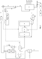
- FIG. 1 A flow diagram including an integrated hydroprocessing and steam pyrolysis process and system including residual bypass is shown in FIG. 1 .
- the integrated system generally includes a feed separation zone 20, a selective catalytic hydroprocessing zone, a steam pyrolysis zone 30 and a product separation zone.
- Feed separation zone 20 includes an inlet for receiving a feedstock stream 1, an outlet for discharging a rejected portion 22 and an outlet for discharging a remaining hydrocarbon portion 2.
- the cut point in separation zone 20 can be set so that it is compatible with the residue fuel oil blend, e.g., about 540°C.
- Separation zone 20 can be a single stage separation device such a flash separator
- separation zone 20 can include, or consists essentially of (i.e., operate in the absence of a flash zone), a cyclonic phase separation device, or other separation device based on physical or mechanical separation of vapors and liquids.
- a vapor-liquid separation device is illustrated by, and with reference to, FIGs. 2A-2C .
- a similar arrangement of a vapor-liquid separation device is also described in U.S. Patent Publication Number 2011/0247500 .
- the cut point can be adjusted based on vaporization temperature and the fluid velocity of the material entering the device.
- Selective hydroprocessing zone includes a hydroprocessing reaction zone 4 having an inlet for receiving a mixture 3 of hydrocarbon portion 21 and hydrogen 2 recycled from the steam pyrolysis product stream and make-up hydrogen as necessary. Hydroprocessing reaction zone 4 further includes an outlet for discharging a hydroprocessed effluent 5.
- Reactor effluents 5 from the hydroprocessing reactor(s) are cooled in a heat exchanger (not shown) and sent to a high pressure separator 6.
- the separator tops 7 are cleaned in an amine unit 12 and a resulting hydrogen rich gas stream 13 is passed to a recycling compressor 14 to be used as a recycle gas 15 in the hydroprocessing reactor.
- a bottoms stream 8 from the high pressure separator 6, which is in a substantially liquid phase, is cooled and introduced to a low pressure cold separator 9 in which it is separated into a gas stream and a liquid stream 10.
- Gases from low pressure cold separator includes hydrogen, H 2 S, NH 3 and any light hydrocarbons such as C 1 -C 4 hydrocarbons.
- stream gas stream 11 which includes hydrogen, H 2 S, NH 3 and any light hydrocarbons such as C 1 -C 4 hydrocarbons, with steam cracker products 44. All or a portion of liquid stream 10 serves as the feed to the steam pyrolysis zone 30
- Steam pyrolysis zone 30 generally comprises a convection section 32 and a pyrolysis section 34 that can operate based on steam pyrolysis unit operations known in the art, i.e., charging the thermal cracking feed to the convection section in the presence of steam.
- a vapor-liquid separation section 36 is included between sections 32 and 34.
- Vapor-liquid separation section 36, through which the heated steam cracking feed from convection section 32 passes, can be a separation device based on physical or mechanical separation of vapors and liquids.
- a vapor-liquid separation illustrated by, and with reference in FIGs. 2A-2C .
- a similar arrangement of a vapor-liquid separation device is also described in U.S. Patent Publication Number 2011/0247500 .
- vapor and liquid flow through in a cyclonic geometry whereby the device operates isothermally and at very low residence time.
- vapor is swirled in a circular pattern to create forces where heavier droplets and liquid are captured and channeled through to a liquid outlet as fuel oil 38, for instance, which is added to a pyrolysis fuel oil blend, and vapor is channeled through a vapor outlet as the charge 37 to the pyrolysis section 34.
- the vaporization temperature and fluid velocity are varied to adjust the approximate temperature cutoff point, for instance in certain embodiments compatible with the residue fuel oil blend, e.g., about 540°C.
- a quenching zone 40 includes an inlet in fluid communication with the outlet of steam pyrolysis zone 30, an inlet for admitting a quenching solution 42, an outlet for discharging the quenched mixed product stream 44 and an outlet for discharging quenching solution 46.
- an intermediate quenched mixed product stream 44 is converted into intermediate product stream 65 and hydrogen 62, which is purified in the present process and used as recycle hydrogen stream 2 in the hydroprocessing reaction zone 4.
- Intermediate product stream 65 is generally fractioned into end-products and residue in separation zone 70, which can one or multiple separation units such as plural fractionation towers including de-ethanizer, de-propanizer and de-butanizer towers, for example as is known to one of ordinary skill in the art.
- suitable apparatus are described in " Ethylene,” Ullmann's Encyclopedia of Industrial Chemistry, Volume 12, Pages 531 - 581 , in particular Fig. 24, Fig 25 and Fig. 26.
- product separation zone 70 includes an inlet in fluid communication with the product stream 65 and plural product outlets 73-78, including an outlet 78 for discharging methane, an outlet 77 for discharging ethylene, an outlet 76 for discharging propylene, an outlet 75 for discharging butadiene, an outlet 74 for discharging mixed butylenes, and an outlet 73 for discharging pyrolysis gasoline. Additionally an outlet is provided for discharging pyrolysis fuel oil 71.
- the rejected portion 22 from the feed separation zone 20 and optionally the rejected portion 38 from vapor-liquid separation section 36 are combined with pyrolysis fuel oil 71 and the mixed stream can be withdrawn as a pyrolysis fuel oil blend 72, e.g., a low sulfur fuel oil blend to be further processed in an off-site refinery or used as fuel for optional power generation zone 120.
- a pyrolysis fuel oil blend 72 e.g., a low sulfur fuel oil blend to be further processed in an off-site refinery or used as fuel for optional power generation zone 120.
- An optional power generation zone 120 can be provided, includes an inlet for receiving fuel oil 72 and an outlet for discharging a remaining portion, e.g., a hydrogen deficient substandard quality feedstock.
- An optional fuel gas desulfurization zone 120 includes an inlet for receiving the remaining portion from the power generation zone 110, and an outlet for discharging a desulfurized fuel gas.
- a crude oil feedstock 1 is introduced into the feed separation zone 20 to produce a rejected portion 22 and a remaining hydrocarbon fraction 21.
- the hydrocarbon fraction 21 is mixed with an effective amount of hydrogen 2 and 15 (and if necessary a source of make-up hydrogen) to form a combined stream 3 and the admixture 3 is charged to the inlet of selective hydroprocessing reaction zone 4 at a temperature in the range of from 300°C to 450°C.
- hydroprocessing reaction zone 4 includes one or more unit operations as described in commonly owned United States Patent Publication Number 2011/0083996 and in PCT Patent Application Publication Numbers WO2010/009077 , WO2010/009082 , WO2010/009089 and WO2009/073436 .
- a hydroprocessing zone can include one or more beds containing an effective amount of hydrodemetallization catalyst, and one or more beds containing an effective amount of hydroprocessing catalyst having hydrodearomatization, hydrodenitrogenation, hydrodesulfurization and/or hydrocracking functions.
- hydroprocessing zone 200 includes more than two catalyst beds.
- hydroprocessing reaction zone 4 includes plural reaction vessels each containing one or more catalyst beds, e.g., of different function.
- Hydroprocessing reaction zone 4 operates under parameters effective to hydrodemetallize, hydrodearomatize, hydrodenitrogenate, hydrodesulfurize and/or hydrocrack the crude oil feedstock.
- hydroprocessing is carried out using the following conditions: operating temperature in the range of from 300°C to 450°C; operating pressure in the range of from 30 bars to 180 bars; and a liquid hour space velocity in the range of from 0.1 h -1 to 10 h -1 .
- operating temperature in the range of from 300°C to 450°C
- operating pressure in the range of from 30 bars to 180 bars
- a liquid hour space velocity in the range of from 0.1 h -1 to 10 h -1 .
- the deactivation rate is around 1°C/month.
- the deactivation rate would be closer to about 3°C/month to 4°C/month.
- the treatment of atmospheric residue typically employs pressure of around 200 bars whereas the present process in which crude oil is treated can operate at a pressure as low as 100 bars.
- this process can be operated at a high throughput when compared to atmospheric residue.
- the LHSV can be as high as 0.5 while that for atmospheric residue is typically 0.25.
- Deactivation at low throughput (0.25 hr -1 ) is 4.2°C/month and deactivation at higher throughput (0.5 hr -1 ) is 2.0°C/month. With every feed which is considered in the industry, the opposite is observed. This can be attributed to the washing effect of the catalyst.
- Reactor effluents 5 from the hydroprocessing zone 4 are cooled in an exchanger (not shown) and sent to a high pressure cold or hot separator 6.
- Separator tops 7 are cleaned in an amine unit 12 and the resulting hydrogen rich gas stream 13 is passed to a recycling compressor 14 to be used as a recycle gas 15 in the hydroprocessing reaction zone 4.
- Separator bottoms 8 from the high pressure separator 6, which are in a substantially liquid phase, are cooled and then introduced to a low pressure cold separator 9.
- Remaining gases, stream 11, including hydrogen, H 2 S, NH 3 and any light hydrocarbons, which can include C 1 -C 4 hydrocarbons, can be conventionally purged from the low pressure cold separator and sent for further processing, such as flare processing or fuel gas processing.
- hydrogen is recovered by combining stream 11 (as indicated by dashed lines) with the cracking gas, stream 44, from the steam cracker products.
- the hydroprocessed effluent 10 contains a reduced content of contaminants (i.e., metals, sulfur and nitrogen), an increased paraffinicity, reduced BMCI, and an increased American Petroleum Institute (API) gravity.
- contaminants i.e., metals, sulfur and nitrogen
- API American Petroleum Institute
- the hydroprocessed effluent 10 is conveyed to the inlet of a convection section 32 in the presence of an effective amount of steam, e.g., admitted via a steam inlet.
- the mixture is heated to a predetermined temperature, e.g., using one or more waste heat streams or other suitable heating arrangement.
- the heated mixture of the pyrolysis feedstream and steam is passed to the pyrolysis section 34 to produce a mixed product stream 39.
- the heated mixture of from section 32 is passed through a vapor-liquid separation section 36 in which a portion 38 is rejected as a fuel oil component suitable for blending with pyrolysis fuel oil 71.
- the steam pyrolysis zone 30 operates under parameters effective to crack effluent 4 into desired products including ethylene, propylene, butadiene, mixed butenes and pyrolysis gasoline.
- steam cracking is carried out using the following conditions: a temperature in the range of from 400°C to 900°C in the convection section and in the pyrolysis section; a steam-to-hydrocarbon ratio in the convection section in the range of from 0.3:1 to 2:1; and a residence time in the convection section and in the pyrolysis section in the range of from 0.05 seconds to 2 seconds.
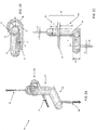
- the vapor-liquid separation section 36 includes one or a plurality of vapor liquid separation devices 80 as shown in FIGs. 2A-2C .
- the vapor liquid separation device 80 is economical to operate and maintenance free since it does not require power or chemical supplies.
- device 80 comprises three ports including an inlet port for receiving a vapor-liquid mixture, a vapor outlet port and a liquid outlet port for discharging and the collection of the separated vapor and liquid, respectively.
- Device 80 operates based on a combination of phenomena including conversion of the linear velocity of the incoming mixture into a rotational velocity by the global flow pre-rotational section, a controlled centrifugal effect to pre-separate the vapor from liquid (residue), and a cyclonic effect to promote separation of vapor from the liquid (residue).
- device 80 includes a pre-rotational section 88, a controlled cyclonic vertical section 90 and a liquid collector/settling section 92.
- the pre-rotational section 88 includes a controlled pre-rotational element between cross-section (S1) and cross-section (S2), and a connection element to the controlled cyclonic vertical section 90 and located between cross-section (S2) and cross-section (S3).
- the vapor liquid mixture coming from inlet 32 having a diameter (D1) enters the apparatus tangentially at the cross-section (S1).
- the area of the entry section (S1) for the incoming flow is at least 10% of the area of the inlet 82 according to the following equation:
- the pre-rotational element 88 defines a curvilinear flow path, and is characterized by constant, decreasing or increasing cross-section from the inlet cross-section S1 to the outlet cross-section S2.
- the ratio between outlet cross-section from controlled pre-rotational element (S2) and the inlet cross-section (S1) is in certain embodiments in the range of 0.7 ⁇ S2/S1 ⁇ 1.4.
- the rotational velocity of the mixture is dependent on the radius of curvature (R1) of the center-line of the pre-rotational element 88 where the center-line is defined as a curvilinear line joining all the center points of successive cross-sectional surfaces of the pre-rotational element 88.
- the radius of curvature (R1) is in the range of 2 ⁇ R1/D1 ⁇ 6 with opening angle in the range of 150° ⁇ ⁇ R1 ⁇ 250°.
- the cross-sectional shape at the inlet section S1 can be a rectangle, a rounded rectangle, a circle, an oval, or other rectilinear, curvilinear or a combination of the aforementioned shapes.
- the shape of the cross-section along the curvilinear path of the pre-rotational element 88 through which the fluid passes progressively changes, for instance, from a generally square shape to a rectangular shape.
- the progressively changing cross-section of element 88 into a rectangular shape advantageously maximizes the opening area, thus allowing the gas to separate from the liquid mixture at an early stage and to attain a uniform velocity profile and minimize shear stresses in the fluid flow.
- connection element includes an opening region that is open and connected to, or integral with, an inlet in the controlled cyclonic vertical section 90.
- the fluid flow enters the controlled cyclonic vertical section 90 at a high rotational velocity to generate the cyclonic effect.
- the ratio between connection element outlet cross-section (S3) and inlet cross-section (S2) in certain embodiments is in the range of 2 ⁇ S 3/S1 ⁇ 5.
- the mixture at a high rotational velocity enters the cyclonic vertical section 90.
- Kinetic energy is decreased and the vapor separates from the liquid under the cyclonic effect.
- Cyclones form in the upper level 90a and the lower level 90b of the cyclonic vertical section 90.
- the mixture is characterized by a high concentration of vapor
- the mixture is characterized by a high concentration of liquid.
- the internal diameter D2 of the cyclonic vertical section 90 is within the range of 2 ⁇ D2/D1 ⁇ 5 and can be constant along its height, the length (LU) of the upper portion 90a is in the range of 1.2 ⁇ LU/D2 ⁇ 3, and the length (LL) of the lower portion 90b is in the range of 2 ⁇ LL/D2 ⁇ 5.
- the end of the cyclonic vertical section 90 proximate vapor outlet 84 is connected to a partially open release riser and connected to the pyrolysis section of the steam pyrolysis unit.
- the diameter (DV) of the partially open release is in certain embodiments in the range of 0.05 ⁇ DV/D2 ⁇ 0.4.
- a large volume fraction of the vapor therein exits device 80 from the outlet 84 through the partially open release pipe with a diameter DV.
- the liquid phase e.g., residue
- the liquid phase exits through a bottom portion of the cyclonic vertical section 90 having a cross-sectional area S4, and is collected in the liquid collector and settling pipe 92.
- connection area between the cyclonic vertical section 90 and the liquid collector and settling pipe 92 has an angle in certain embodiment of 90°.
- the internal diameter of the liquid collector and settling pipe 92 is in the range of 2 ⁇ D3/D1 ⁇ 4 and is constant across the pipe length, and the length (LH) of the liquid collector and settling pipe 92 is in the range of 1.2 ⁇ LH/D3 ⁇ 5.
- the liquid with low vapor volume fraction is removed from the apparatus through pipe 86 having a diameter of DL, which in certain embodiments is in the range of 0.05 ⁇ DL/D3 ⁇ 0.4 and located at the bottom or proximate the bottom of the settling pipe
- apparatus 80 can be formed as a monolithic structure, e.g., it can be cast or molded, or it can be assembled from separate parts, e.g., by welding or otherwise attaching separate components together which may or may not correspond precisely to the members and portions described herein.
- Mixed product stream 39 is passed to the inlet of quenching zone 40 with a quenching solution 42 (e.g., water and/or pyrolysis fuel oil) introduced via a separate inlet to produce an intermediate quenched mixed product stream 44 having a reduced temperature, e.g., of about 300°C, and spent quenching solution 46 is discharged.
- the gas mixture effluent 39 from the cracker is typically a mixture of hydrogen, methane, hydrocarbons, carbon dioxide and hydrogen sulfide.
- mixture 44 is compressed in a multi-stage compressor zone 51, typically in 4-6 stages to produce a compressed gas mixture 52.
- the compressed gas mixture 52 is treated in a caustic treatment unit 53 to produce a gas mixture 54 depleted of hydrogen sulfide and carbon dioxide.
- the gas mixture 54 is further compressed in a compressor zone 55, and the resulting cracked gas 56 typically undergoes a cryogenic treatment in unit 57 to be dehydrated, and is further dried by use of molecular sieves.
- the cold cracked gas stream 58 from unit 57 is passed to a de-methanizer tower 59, from which an overhead stream 60 is produced containing hydrogen and methane from the cracked gas stream.
- the bottoms stream 65 from de-methanizer tower 59 is then sent for further processing in product separation zone 70, comprising fractionation towers including de-ethanizer, de-propanizer and de-butanizer towers. Process configurations with a different sequence of de-methanizer, de-ethanizer, de-propanizer and de-butanizer can also be employed.
- hydrogen 62 having a purity of typically 80-95 vol% is obtained.
- Recovery methods in unit 61 include cryogenic recovery (e.g., at a temperature of about -157°C).
- Hydrogen stream 62 is then passed to a hydrogen purification unit 64, such as a pressure swing adsorption (PSA) unit to obtain a hydrogen stream 2 having a purity of 99.9%+, or a membrane separation units to obtain a hydrogen stream 2 with a purity of about 95%.
- PSA pressure swing adsorption
- the purified hydrogen stream 2 is then recycled back to serve as a major portion of the requisite hydrogen for the hydroprocessing zone.
- methane stream 63 can optionally be recycled to the steam cracker to be used as fuel for burners and/or heaters.
- the bottoms stream 65 from de-methanizer tower 59 is conveyed to the inlet of product separation zone 70 to be separated into methane, ethylene, propylene, butadiene, mixed butylenes and pyrolysis gasoline discharged via outlets 78, 77, 76, 75, 74 and 73, respectively.
- Pyrolysis gasoline generally includes C5-C9 hydrocarbons, and benzene, toluene and xylenes can be extracted from this cut.
- the rejected portion 22 from the feed separation zone 100 and optionally the unvaporized heavy liquid fraction 38 from the vapor-liquid separation section 36 are combined with pyrolysis fuel oil 71 (e.g., materials boiling at a temperature higher than the boiling point of the lowest boiling C10 compound, known as a "C10+" stream) from separation zone 70, and this is withdrawn as a pyrolysis fuel oil blend 72, e.g., to be further processed in an off-site refinery (not shown).
- pyrolysis fuel oil 71 e.g., materials boiling at a temperature higher than the boiling point of the lowest boiling C10 compound, known as a "C10+" stream
- fuel oil 72 can be passed to power generation zone 110 to generate power (e.g., one or more steam turbines that can employ fuel oil 72 as a fuel source), and a remaining portion is conveyed to a fuel gas desulfurization zone 120 to produce a desulfurized fuel gas.
- power generation zone 110 to generate power
- fuel gas desulfurization zone 120 to produce a desulfurized fuel gas.
- Advantages of the system described with respect to FIG. 1 include improvements in hydroprocessing, in which the process can be efficiently utilized to improve the hydrogen content of the products.
- the system described herein uses hydrotreating catalyst having smaller pore size which contributes to significantly more active hydrotreating reactions.
- the overall hydrogen consumption of the hydrotreating zone is significantly reduced. Hydrogen is not consumed for upgrading unsatureated heavy residue, but rather is utilized for the fraction undergoing pyrolysis reaction, e.g., fractions boiling below 540°C.
- the heavier fraction e.g., boiling above 540°C, is used to generate power for the plant, while the remaining portion is recovered as fuel oil.
- selective hydroprocessing or hydrotreating processes can increase the paraffin content (or decrease the BMCI) of a feedstock by saturation followed by mild hydrocracking of aromatics, especially polyaromatics.
- contaminants such as metals, sulfur and nitrogen can be removed by passing the feedstock through a series of layered catalysts that perform the catalytic functions of demetallization, desulfurization and/or denitrogenation.
- the sequence of catalysts to perform hydrodemetallization (HDM) and hydrodesulfurization (HDS) is as follows:
- hydrogen produced from the steam cracking zone is recycled to the hydroprocessing zone to minimize the demand for fresh hydrogen.
- the integrated systems described herein only require fresh hydrogen to initiate the operation. Once the reaction reaches the equilibrium, the hydrogen purification system can provide enough high purity hydrogen to maintain the operation of the entire system.
Claims (8)
- Procédé d'hydrotraitement et de pyrolyse en phase vapeur intégré pour le traitement direct d'un pétrole brut pour produire un mélange d'huile combustible et des produits pétrochimiques oléfiniques et aromatiques, le procédé comprenant :a. la séparation du pétrole brut en composants légers et composants lourds ;b. le chargement des composants légers et d'hydrogène dans une zone d'hydrotraitement fonctionnant dans des conditions efficaces pour produire un effluent soumis à hydrotraitement ayant une teneur réduite en contaminants, une capacité paraffinique augmentée, un indice de corrélation du Bureau of Mines réduit et une gravité de l'American Petroleum Institute augmentée ;c. le craquage thermique de l'effluent soumis à hydrotraitement en présence de vapeur pour produire un flux de produit mélangé ;d. la séparation du flux de produit mélangé craqué thermiquement ;e. la purification de l'hydrogène récupéré dans l'étape (d) et son recyclage dans l'étape (b) ;f. la récupération d'oléfines et d'aromatiques à partir du flux de produit mélangé séparé ; etg. la récupération d'un flux combiné d'huile combustible de pyrolyse à partir du flux de produit mélangé séparé et de composants lourds provenant de l'étape (a) comme un mélange d'huile combustible.
- Procédé intégré selon la revendication 1, comprenant en outre la séparation des effluents du réacteur de zone d'hydrotraitement dans un séparateur à haute pression pour récupérer
une portion gazeuse qui est nettoyée et recyclée dans la zone d'hydrotraitement comme une source additionnelle d'hydrogène, et
une portion liquide, et
la séparation de la portion liquide provenant du séparateur à haute pression dans un séparateur à basse pression en une portion gazeuse et une portion liquide, dans lequel la portion liquide provenant du séparateur à basse pression est l'effluent soumis à hydrotraitement soumis au craquage thermique et la portion gazeuse provenant du séparateur à basse pression est combinée avec le flux de produit mélangé après la zone de pyrolyse en phase vapeur et avant la séparation dans l'étape (d). - Procédé intégré selon la revendication 1, dans lequel l'étape de craquage thermique comprend le chauffage de l'effluent soumis à hydrotraitement dans une section de convection d'une zone de pyrolyse en phase vapeur, la séparation de l'effluent soumis à hydrotraitement chauffé en une fraction de vapeur et une fraction liquide, le transfert de la fraction de vapeur à une section de pyrolyse d'une zone de pyrolyse en phase vapeur, et le déchargement de la fraction liquide.
- Procédé intégré selon la revendication 3, dans lequel la fraction liquide déchargée est mélangée avec de l'huile combustible de pyrolyse récupérée dans l'étape (g).
- Procédé intégré selon la revendication 3, dans lequel la séparation de l'effluent soumis à hydrotraitement chauffé en une fraction de vapeur et une fraction liquide est effectuée avec un dispositif de séparation vapeur-liquide basé sur une séparation physique et mécanique.
- Procédé intégré selon la revendication 5, dans lequel le dispositif de séparation vapeur-liquide inclut
un élément de pré-rotation ayant une portion d'entrée et une portion de transition, la portion d'entrée ayant une entrée pour recevoir le mélange de fluide d'écoulant et un conduit curviligne,
une section cyclonique contrôlée ayant
une entrée jouxtant l'élément de pré-rotation par le biais d'une convergence du conduit curviligne et de la section cyclonique,
une section ascendante à une extrémité supérieure de l'élément cyclonique à travers laquelle passent les vapeurs ;
et
une section de collecteur de liquide/décantation à travers laquelle passe le liquide. - Procédé intégré selon la revendication 1, dans lequel
l'étape (d) comprend
la compression du flux de produit mélangé craqué thermiquement avec une pluralité d'étages de compression ;
le fait de soumettre le flux de produit mélangé craqué thermiquement comprimé à un traitement caustique pour produire un flux de produit mélangé craqué thermiquement avec une teneur réduite en sulfure d'hydrogène et en dioxyde de carbone ;
la compression du flux de produit mélangé craqué thermiquement avec une teneur réduite en sulfure d'hydrogène et en dioxyde de carbone ;
la déshydratation du flux de produit mélangé craqué thermiquement comprimé avec une teneur réduite en sulfure d'hydrogène et en dioxyde de carbone ;
la récupération d'hydrogène à partir du flux de produit mélangé craqué thermiquement comprimé déshydraté avec une teneur réduite en sulfure d'hydrogène et en dioxyde de carbone ; et
l'obtention d'oléfines et d'aromatiques comme dans l'étape (e) et d'huile combustible de pyrolyse comme dans l'étape (f) à partir du reste du flux de produit mélangé craqué thermiquement comprimé déshydraté avec une teneur réduite en sulfure d'hydrogène et en dioxyde de carbone ;
et
l'étape (e) comprend la purification de l'hydrogène récupéré à partir du flux de produit mélangé craqué thermiquement comprimé déshydraté avec une teneur réduite en sulfure d'hydrogène et en dioxyde de carbone pour le recyclage dans la zone d'hydrotraitement. - Procédé intégré selon la revendication 7, dans lequel la récupération d'hydrogène à partir du flux de produit mélangé craqué thermiquement comprimé déshydraté avec une teneur réduite en sulfure d'hydrogène et en dioxyde de carbone comprend en outre la récupération séparée de méthane pour l'utilisation comme combustible pour des brûleurs et/ou des réchauffeurs dans l'étape de craquage thermique.
Applications Claiming Priority (2)
| Application Number | Priority Date | Filing Date | Title |
|---|---|---|---|
| US201261591816P | 2012-01-27 | 2012-01-27 | |
| PCT/US2013/023337 WO2013112970A1 (fr) | 2012-01-27 | 2013-01-27 | Procédé intégré de pyrolyse à la vapeur et d'hydrotraitement incluant une dérivation résiduelle pour le traitement direct d'un pétrole brut |
Publications (2)
| Publication Number | Publication Date |
|---|---|
| EP2807235A1 EP2807235A1 (fr) | 2014-12-03 |
| EP2807235B1 true EP2807235B1 (fr) | 2021-03-17 |
Family
ID=47891896
Family Applications (1)
| Application Number | Title | Priority Date | Filing Date |
|---|---|---|---|
| EP13710090.5A Active EP2807235B1 (fr) | 2012-01-27 | 2013-01-27 | Procédé intégré de pyrolyse à la vapeur et d'hydrotraitement incluant une dérivation résiduelle pour le traitement direct d'un pétrole brut |
Country Status (7)
| Country | Link |
|---|---|
| US (1) | US20130197283A1 (fr) |
| EP (1) | EP2807235B1 (fr) |
| JP (2) | JP6151718B2 (fr) |
| KR (1) | KR102061186B1 (fr) |
| CN (1) | CN104105783B (fr) |
| SG (1) | SG11201404387QA (fr) |
| WO (1) | WO2013112970A1 (fr) |
Families Citing this family (9)
| Publication number | Priority date | Publication date | Assignee | Title |
|---|---|---|---|---|
| US9255230B2 (en) * | 2012-01-27 | 2016-02-09 | Saudi Arabian Oil Company | Integrated hydrotreating and steam pyrolysis process for direct processing of a crude oil |
| CN103699160B (zh) * | 2013-12-24 | 2016-02-10 | 北京航天时代光电科技有限公司 | 一种高精度气体定量定压供应装置 |
| WO2015128042A1 (fr) * | 2014-02-25 | 2015-09-03 | Saudi Basic Industries Corporation | Procédé de réglage de l'apport et de la répartition d'hydrogène gazeux dans un système d'hydrogène d'une raffinerie intégrée avec des installations de production d'oléfines et de composés aromatiques |
| EP3577199B1 (fr) | 2017-02-02 | 2021-12-22 | SABIC Global Technologies B.V. | Procédé intégré d'hydrotraitement et de pyrolyse à la vapeur pour le traitement direct d'un pétrole brut pour produire des produits pétrochimiques oléfiniques et aromatiques |
| US10689587B2 (en) * | 2017-04-26 | 2020-06-23 | Saudi Arabian Oil Company | Systems and processes for conversion of crude oil |
| CN110997601B (zh) * | 2017-08-15 | 2021-01-29 | Sabic环球技术有限责任公司 | 通过集成的蒸汽裂解和加氢裂解方法生产轻质烯烃 |
| KR20220050085A (ko) | 2019-03-15 | 2022-04-22 | 루머스 테크놀로지 엘엘씨 | 증기 분해 전 희석 증기를 액상 탄화수소와 혼합하는 방법 |
| US11279891B2 (en) * | 2020-03-05 | 2022-03-22 | Saudi Arabian Oil Company | Systems and processes for direct crude oil upgrading to hydrogen and chemicals |
| JP7089101B2 (ja) * | 2021-09-27 | 2022-06-21 | 住友化学株式会社 | 水素の製造方法および製造システム |
Family Cites Families (18)
| Publication number | Priority date | Publication date | Assignee | Title |
|---|---|---|---|---|
| US3482138A (en) | 1967-05-16 | 1969-12-02 | Perkin Elmer Corp | Germanium hollow cathode assembly for lamps |
| BE793036A (fr) * | 1971-12-21 | 1973-04-16 | Pierrefitte Auby Sa | Procede de craquage sous pression d'hydrogene pour la production d'olefines |
| GB1504776A (en) | 1975-08-14 | 1978-03-22 | Davy Powergas Ltd | Hydrocracking c3 or higher hydrocarbon feedstock |
| US4002556A (en) | 1976-04-12 | 1977-01-11 | Continental Oil Company | Multiple point injection of hydrogen donor diluent in thermal cracking |
| JPS5898387A (ja) * | 1981-12-09 | 1983-06-11 | Asahi Chem Ind Co Ltd | ガス状オレフイン及び単環芳香族炭化水素の製造方法 |
| US5906728A (en) | 1996-08-23 | 1999-05-25 | Exxon Chemical Patents Inc. | Process for increased olefin yields from heavy feedstocks |
| FR2867988B1 (fr) | 2004-03-23 | 2007-06-22 | Inst Francais Du Petrole | Catalyseur supporte dope de forme spherique et procede d'hydrotraitement et d'hydroconversion de fractions petrolieres contenant des metaux |
| US8696888B2 (en) * | 2005-10-20 | 2014-04-15 | Exxonmobil Chemical Patents Inc. | Hydrocarbon resid processing |
| CN101292013B (zh) * | 2005-10-20 | 2012-10-24 | 埃克森美孚化学专利公司 | 烃残油处理和减粘裂化蒸汽裂化器的原料 |
| MY148309A (en) * | 2006-12-11 | 2013-03-29 | Shell Int Research | Apparatus and method for superheated vapor contacting and vaporization of feedstocks containing high boiling point and unvaporizable foulants in an olefins furnace |
| JP5105326B2 (ja) * | 2007-04-19 | 2012-12-26 | 昭和電工株式会社 | 水素化方法及び石油化学プロセス |
| EP2234710A2 (fr) | 2007-11-28 | 2010-10-06 | Saudi Arabian Oil Company | Processus d'hydrotraitement catalytique des pétroles bruts sulfureux |
| US8372267B2 (en) | 2008-07-14 | 2013-02-12 | Saudi Arabian Oil Company | Process for the sequential hydroconversion and hydrodesulfurization of whole crude oil |
| WO2010009077A2 (fr) | 2008-07-14 | 2010-01-21 | Saudi Arabian Oil Company | Processus de traitement d'huiles lourdes au moyen de composants hydrocarbures légers utilisés comme diluent |
| US20100018904A1 (en) | 2008-07-14 | 2010-01-28 | Saudi Arabian Oil Company | Prerefining Process for the Hydrodesulfurization of Heavy Sour Crude Oils to Produce Sweeter Lighter Crudes Using Moving Catalyst System |
| EP2445997B1 (fr) | 2009-06-22 | 2021-03-24 | Saudi Arabian Oil Company | Demetallisation et desulfurisation d'un petrole brut por coquage retardé |
| EP2336272A1 (fr) * | 2009-12-15 | 2011-06-22 | Total Petrochemicals Research Feluy | Décongestionnement d'une unité de craquage à vapeur pour améliorer la production de propylène |
| WO2011130259A1 (fr) | 2010-04-12 | 2011-10-20 | Saudi Arabian Oil Company | Appareil de séparation de mélanges gaz-liquide et favorisant coalescence de liquides |
-
2013
- 2013-01-27 WO PCT/US2013/023337 patent/WO2013112970A1/fr active Application Filing
- 2013-01-27 EP EP13710090.5A patent/EP2807235B1/fr active Active
- 2013-01-27 CN CN201380006610.6A patent/CN104105783B/zh active Active
- 2013-01-27 JP JP2014554905A patent/JP6151718B2/ja not_active Expired - Fee Related
- 2013-01-27 KR KR1020147024066A patent/KR102061186B1/ko active IP Right Grant
- 2013-01-27 SG SG11201404387QA patent/SG11201404387QA/en unknown
- 2013-01-28 US US13/751,395 patent/US20130197283A1/en not_active Abandoned
-
2017
- 2017-05-18 JP JP2017098615A patent/JP6491260B2/ja active Active
Non-Patent Citations (1)
| Title |
|---|
| None * |
Also Published As
| Publication number | Publication date |
|---|---|
| JP2015509128A (ja) | 2015-03-26 |
| US20130197283A1 (en) | 2013-08-01 |
| JP6491260B2 (ja) | 2019-03-27 |
| JP6151718B2 (ja) | 2017-06-21 |
| WO2013112970A1 (fr) | 2013-08-01 |
| KR20140138141A (ko) | 2014-12-03 |
| CN104105783A (zh) | 2014-10-15 |
| CN104105783B (zh) | 2016-11-23 |
| JP2017197748A (ja) | 2017-11-02 |
| KR102061186B1 (ko) | 2019-12-31 |
| SG11201404387QA (en) | 2014-10-30 |
| EP2807235A1 (fr) | 2014-12-03 |
Similar Documents
| Publication | Publication Date | Title |
|---|---|---|
| US10883058B2 (en) | Integrated hydrotreating and steam pyrolysis process including residual bypass for direct processing of a crude oil | |
| US10329499B2 (en) | Integrated hydrotreating and steam pyrolysis system including hydrogen redistribution for direct processing of a crude oil | |
| US10017704B2 (en) | Integrated hydrotreating and steam pyrolysis system for direct processing of a crude oil | |
| US9382486B2 (en) | Integrated hydrotreating, solvent deasphalting and steam pyrolysis process for direct processing of a crude oil | |
| US9284502B2 (en) | Integrated solvent deasphalting, hydrotreating and steam pyrolysis process for direct processing of a crude oil | |
| US9228141B2 (en) | Integrated hydroprocessing, steam pyrolysis and slurry hydroprocessing of crude oil to produce petrochemicals | |
| EP2828356B1 (fr) | Hydrotraitement intégré et pyrolyse à la vapeur de pétrole brut pour produire des oléfines légères et du coke | |
| EP2807236B1 (fr) | Procédé d'hydrotraitement et de pyrolyse en phase vapeur intégré pour le traitement direct d'un pétrole brut | |
| EP2807235B1 (fr) | Procédé intégré de pyrolyse à la vapeur et d'hydrotraitement incluant une dérivation résiduelle pour le traitement direct d'un pétrole brut | |
| EP2807237B1 (fr) | Procédé de pyrolyse à la vapeur et d'hydrotraitement intégré incluant une rédistribution d'hydrogène pour le traitement direct d'un pétrole brut | |
| EP2807233B1 (fr) | Procédé intégré de désasphaltage au solvant, d'hydrotraitement et de pyrolyse à la vapeur pour le traitement direct de pétrole brut | |
| US20130197284A1 (en) | Integrated hydrotreating, solvent deasphalting and steam pyrolysis process for direct processing of a crude oil |
Legal Events
| Date | Code | Title | Description |
|---|---|---|---|
| PUAI | Public reference made under article 153(3) epc to a published international application that has entered the european phase |
Free format text: ORIGINAL CODE: 0009012 |
|
| 17P | Request for examination filed |
Effective date: 20140827 |
|
| AK | Designated contracting states |
Kind code of ref document: A1 Designated state(s): AL AT BE BG CH CY CZ DE DK EE ES FI FR GB GR HR HU IE IS IT LI LT LU LV MC MK MT NL NO PL PT RO RS SE SI SK SM TR |
|
| DAX | Request for extension of the european patent (deleted) | ||
| RIN1 | Information on inventor provided before grant (corrected) |
Inventor name: SAYED, ESSAM Inventor name: BOURANE, ABDENNOUR Inventor name: SHAFI, RAHEEL Inventor name: AKHRAS, ABDUL RAHMAN, ZAFER Inventor name: ABBA, ABRAHIM, A. |
|
| GRAP | Despatch of communication of intention to grant a patent |
Free format text: ORIGINAL CODE: EPIDOSNIGR1 |
|
| STAA | Information on the status of an ep patent application or granted ep patent |
Free format text: STATUS: GRANT OF PATENT IS INTENDED |
|
| INTG | Intention to grant announced |
Effective date: 20200723 |
|
| GRAJ | Information related to disapproval of communication of intention to grant by the applicant or resumption of examination proceedings by the epo deleted |
Free format text: ORIGINAL CODE: EPIDOSDIGR1 |
|
| STAA | Information on the status of an ep patent application or granted ep patent |
Free format text: STATUS: REQUEST FOR EXAMINATION WAS MADE |
|
| INTC | Intention to grant announced (deleted) | ||
| GRAS | Grant fee paid |
Free format text: ORIGINAL CODE: EPIDOSNIGR3 |
|
| STAA | Information on the status of an ep patent application or granted ep patent |
Free format text: STATUS: GRANT OF PATENT IS INTENDED |
|
| GRAP | Despatch of communication of intention to grant a patent |
Free format text: ORIGINAL CODE: EPIDOSNIGR1 |
|
| STAA | Information on the status of an ep patent application or granted ep patent |
Free format text: STATUS: GRANT OF PATENT IS INTENDED |
|
| INTG | Intention to grant announced |
Effective date: 20210114 |
|
| GRAA | (expected) grant |
Free format text: ORIGINAL CODE: 0009210 |
|
| STAA | Information on the status of an ep patent application or granted ep patent |
Free format text: STATUS: THE PATENT HAS BEEN GRANTED |
|
| AK | Designated contracting states |
Kind code of ref document: B1 Designated state(s): AL AT BE BG CH CY CZ DE DK EE ES FI FR GB GR HR HU IE IS IT LI LT LU LV MC MK MT NL NO PL PT RO RS SE SI SK SM TR |
|
| REG | Reference to a national code |
Ref country code: GB Ref legal event code: FG4D |
|
| REG | Reference to a national code |
Ref country code: CH Ref legal event code: EP |
|
| REG | Reference to a national code |
Ref country code: DE Ref legal event code: R096 Ref document number: 602013076299 Country of ref document: DE |
|
| REG | Reference to a national code |
Ref country code: IE Ref legal event code: FG4D |
|
| REG | Reference to a national code |
Ref country code: AT Ref legal event code: REF Ref document number: 1372253 Country of ref document: AT Kind code of ref document: T Effective date: 20210415 |
|
| REG | Reference to a national code |
Ref country code: NL Ref legal event code: FP |
|
| REG | Reference to a national code |
Ref country code: LT Ref legal event code: MG9D |
|
| PG25 | Lapsed in a contracting state [announced via postgrant information from national office to epo] |
Ref country code: FI Free format text: LAPSE BECAUSE OF FAILURE TO SUBMIT A TRANSLATION OF THE DESCRIPTION OR TO PAY THE FEE WITHIN THE PRESCRIBED TIME-LIMIT Effective date: 20210317 Ref country code: HR Free format text: LAPSE BECAUSE OF FAILURE TO SUBMIT A TRANSLATION OF THE DESCRIPTION OR TO PAY THE FEE WITHIN THE PRESCRIBED TIME-LIMIT Effective date: 20210317 Ref country code: GR Free format text: LAPSE BECAUSE OF FAILURE TO SUBMIT A TRANSLATION OF THE DESCRIPTION OR TO PAY THE FEE WITHIN THE PRESCRIBED TIME-LIMIT Effective date: 20210618 Ref country code: BG Free format text: LAPSE BECAUSE OF FAILURE TO SUBMIT A TRANSLATION OF THE DESCRIPTION OR TO PAY THE FEE WITHIN THE PRESCRIBED TIME-LIMIT Effective date: 20210617 Ref country code: NO Free format text: LAPSE BECAUSE OF FAILURE TO SUBMIT A TRANSLATION OF THE DESCRIPTION OR TO PAY THE FEE WITHIN THE PRESCRIBED TIME-LIMIT Effective date: 20210617 |
|
| REG | Reference to a national code |
Ref country code: AT Ref legal event code: MK05 Ref document number: 1372253 Country of ref document: AT Kind code of ref document: T Effective date: 20210317 |
|
| PG25 | Lapsed in a contracting state [announced via postgrant information from national office to epo] |
Ref country code: SE Free format text: LAPSE BECAUSE OF FAILURE TO SUBMIT A TRANSLATION OF THE DESCRIPTION OR TO PAY THE FEE WITHIN THE PRESCRIBED TIME-LIMIT Effective date: 20210317 Ref country code: RS Free format text: LAPSE BECAUSE OF FAILURE TO SUBMIT A TRANSLATION OF THE DESCRIPTION OR TO PAY THE FEE WITHIN THE PRESCRIBED TIME-LIMIT Effective date: 20210317 Ref country code: LV Free format text: LAPSE BECAUSE OF FAILURE TO SUBMIT A TRANSLATION OF THE DESCRIPTION OR TO PAY THE FEE WITHIN THE PRESCRIBED TIME-LIMIT Effective date: 20210317 |
|
| PG25 | Lapsed in a contracting state [announced via postgrant information from national office to epo] |
Ref country code: SM Free format text: LAPSE BECAUSE OF FAILURE TO SUBMIT A TRANSLATION OF THE DESCRIPTION OR TO PAY THE FEE WITHIN THE PRESCRIBED TIME-LIMIT Effective date: 20210317 Ref country code: AT Free format text: LAPSE BECAUSE OF FAILURE TO SUBMIT A TRANSLATION OF THE DESCRIPTION OR TO PAY THE FEE WITHIN THE PRESCRIBED TIME-LIMIT Effective date: 20210317 Ref country code: EE Free format text: LAPSE BECAUSE OF FAILURE TO SUBMIT A TRANSLATION OF THE DESCRIPTION OR TO PAY THE FEE WITHIN THE PRESCRIBED TIME-LIMIT Effective date: 20210317 Ref country code: CZ Free format text: LAPSE BECAUSE OF FAILURE TO SUBMIT A TRANSLATION OF THE DESCRIPTION OR TO PAY THE FEE WITHIN THE PRESCRIBED TIME-LIMIT Effective date: 20210317 Ref country code: LT Free format text: LAPSE BECAUSE OF FAILURE TO SUBMIT A TRANSLATION OF THE DESCRIPTION OR TO PAY THE FEE WITHIN THE PRESCRIBED TIME-LIMIT Effective date: 20210317 |
|
| PG25 | Lapsed in a contracting state [announced via postgrant information from national office to epo] |
Ref country code: RO Free format text: LAPSE BECAUSE OF FAILURE TO SUBMIT A TRANSLATION OF THE DESCRIPTION OR TO PAY THE FEE WITHIN THE PRESCRIBED TIME-LIMIT Effective date: 20210317 Ref country code: IS Free format text: LAPSE BECAUSE OF FAILURE TO SUBMIT A TRANSLATION OF THE DESCRIPTION OR TO PAY THE FEE WITHIN THE PRESCRIBED TIME-LIMIT Effective date: 20210717 Ref country code: SK Free format text: LAPSE BECAUSE OF FAILURE TO SUBMIT A TRANSLATION OF THE DESCRIPTION OR TO PAY THE FEE WITHIN THE PRESCRIBED TIME-LIMIT Effective date: 20210317 Ref country code: PT Free format text: LAPSE BECAUSE OF FAILURE TO SUBMIT A TRANSLATION OF THE DESCRIPTION OR TO PAY THE FEE WITHIN THE PRESCRIBED TIME-LIMIT Effective date: 20210719 Ref country code: PL Free format text: LAPSE BECAUSE OF FAILURE TO SUBMIT A TRANSLATION OF THE DESCRIPTION OR TO PAY THE FEE WITHIN THE PRESCRIBED TIME-LIMIT Effective date: 20210317 Ref country code: ES Free format text: LAPSE BECAUSE OF FAILURE TO SUBMIT A TRANSLATION OF THE DESCRIPTION OR TO PAY THE FEE WITHIN THE PRESCRIBED TIME-LIMIT Effective date: 20210317 |
|
| REG | Reference to a national code |
Ref country code: DE Ref legal event code: R097 Ref document number: 602013076299 Country of ref document: DE |
|
| PLBE | No opposition filed within time limit |
Free format text: ORIGINAL CODE: 0009261 |
|
| STAA | Information on the status of an ep patent application or granted ep patent |
Free format text: STATUS: NO OPPOSITION FILED WITHIN TIME LIMIT |
|
| PG25 | Lapsed in a contracting state [announced via postgrant information from national office to epo] |
Ref country code: AL Free format text: LAPSE BECAUSE OF FAILURE TO SUBMIT A TRANSLATION OF THE DESCRIPTION OR TO PAY THE FEE WITHIN THE PRESCRIBED TIME-LIMIT Effective date: 20210317 Ref country code: DK Free format text: LAPSE BECAUSE OF FAILURE TO SUBMIT A TRANSLATION OF THE DESCRIPTION OR TO PAY THE FEE WITHIN THE PRESCRIBED TIME-LIMIT Effective date: 20210317 |
|
| 26N | No opposition filed |
Effective date: 20211220 |
|
| PG25 | Lapsed in a contracting state [announced via postgrant information from national office to epo] |
Ref country code: SI Free format text: LAPSE BECAUSE OF FAILURE TO SUBMIT A TRANSLATION OF THE DESCRIPTION OR TO PAY THE FEE WITHIN THE PRESCRIBED TIME-LIMIT Effective date: 20210317 |
|
| PG25 | Lapsed in a contracting state [announced via postgrant information from national office to epo] |
Ref country code: IT Free format text: LAPSE BECAUSE OF FAILURE TO SUBMIT A TRANSLATION OF THE DESCRIPTION OR TO PAY THE FEE WITHIN THE PRESCRIBED TIME-LIMIT Effective date: 20210317 |
|
| PG25 | Lapsed in a contracting state [announced via postgrant information from national office to epo] |
Ref country code: IS Free format text: LAPSE BECAUSE OF FAILURE TO SUBMIT A TRANSLATION OF THE DESCRIPTION OR TO PAY THE FEE WITHIN THE PRESCRIBED TIME-LIMIT Effective date: 20210717 |
|
| PG25 | Lapsed in a contracting state [announced via postgrant information from national office to epo] |
Ref country code: MC Free format text: LAPSE BECAUSE OF FAILURE TO SUBMIT A TRANSLATION OF THE DESCRIPTION OR TO PAY THE FEE WITHIN THE PRESCRIBED TIME-LIMIT Effective date: 20210317 |
|
| REG | Reference to a national code |
Ref country code: CH Ref legal event code: PL |
|
| GBPC | Gb: european patent ceased through non-payment of renewal fee |
Effective date: 20220127 |
|
| REG | Reference to a national code |
Ref country code: BE Ref legal event code: MM Effective date: 20220131 |
|
| PG25 | Lapsed in a contracting state [announced via postgrant information from national office to epo] |
Ref country code: LU Free format text: LAPSE BECAUSE OF NON-PAYMENT OF DUE FEES Effective date: 20220127 Ref country code: GB Free format text: LAPSE BECAUSE OF NON-PAYMENT OF DUE FEES Effective date: 20220127 |
|
| PG25 | Lapsed in a contracting state [announced via postgrant information from national office to epo] |
Ref country code: BE Free format text: LAPSE BECAUSE OF NON-PAYMENT OF DUE FEES Effective date: 20220131 |
|
| PG25 | Lapsed in a contracting state [announced via postgrant information from national office to epo] |
Ref country code: LI Free format text: LAPSE BECAUSE OF NON-PAYMENT OF DUE FEES Effective date: 20220131 Ref country code: CH Free format text: LAPSE BECAUSE OF NON-PAYMENT OF DUE FEES Effective date: 20220131 |
|
| PG25 | Lapsed in a contracting state [announced via postgrant information from national office to epo] |
Ref country code: IE Free format text: LAPSE BECAUSE OF NON-PAYMENT OF DUE FEES Effective date: 20220127 |
|
| P01 | Opt-out of the competence of the unified patent court (upc) registered |
Effective date: 20230529 |
|
| PGFP | Annual fee paid to national office [announced via postgrant information from national office to epo] |
Ref country code: NL Payment date: 20231219 Year of fee payment: 12 Ref country code: FR Payment date: 20231219 Year of fee payment: 12 |
|
| PG25 | Lapsed in a contracting state [announced via postgrant information from national office to epo] |
Ref country code: HU Free format text: LAPSE BECAUSE OF FAILURE TO SUBMIT A TRANSLATION OF THE DESCRIPTION OR TO PAY THE FEE WITHIN THE PRESCRIBED TIME-LIMIT; INVALID AB INITIO Effective date: 20130127 |
|
| PG25 | Lapsed in a contracting state [announced via postgrant information from national office to epo] |
Ref country code: MK Free format text: LAPSE BECAUSE OF FAILURE TO SUBMIT A TRANSLATION OF THE DESCRIPTION OR TO PAY THE FEE WITHIN THE PRESCRIBED TIME-LIMIT Effective date: 20210317 Ref country code: CY Free format text: LAPSE BECAUSE OF FAILURE TO SUBMIT A TRANSLATION OF THE DESCRIPTION OR TO PAY THE FEE WITHIN THE PRESCRIBED TIME-LIMIT Effective date: 20210317 |
|
| PGFP | Annual fee paid to national office [announced via postgrant information from national office to epo] |
Ref country code: DE Payment date: 20231219 Year of fee payment: 12 |