EP2807083B1 - Artikeltransportbehälter und artikeltransportbehälterzuschnitt - Google Patents
Artikeltransportbehälter und artikeltransportbehälterzuschnitt Download PDFInfo
- Publication number
- EP2807083B1 EP2807083B1 EP13702853.6A EP13702853A EP2807083B1 EP 2807083 B1 EP2807083 B1 EP 2807083B1 EP 13702853 A EP13702853 A EP 13702853A EP 2807083 B1 EP2807083 B1 EP 2807083B1
- Authority
- EP
- European Patent Office
- Prior art keywords
- layer
- flap
- anchor
- floor
- tri
- Prior art date
- Legal status (The legal status is an assumption and is not a legal conclusion. Google has not performed a legal analysis and makes no representation as to the accuracy of the status listed.)
- Active
Links
Images



Classifications
-
- B—PERFORMING OPERATIONS; TRANSPORTING
- B65—CONVEYING; PACKING; STORING; HANDLING THIN OR FILAMENTARY MATERIAL
- B65D—CONTAINERS FOR STORAGE OR TRANSPORT OF ARTICLES OR MATERIALS, e.g. BAGS, BARRELS, BOTTLES, BOXES, CANS, CARTONS, CRATES, DRUMS, JARS, TANKS, HOPPERS, FORWARDING CONTAINERS; ACCESSORIES, CLOSURES, OR FITTINGS THEREFOR; PACKAGING ELEMENTS; PACKAGES
- B65D5/00—Rigid or semi-rigid containers of polygonal cross-section, e.g. boxes, cartons or trays, formed by folding or erecting one or more blanks made of paper
- B65D5/001—Rigid or semi-rigid containers of polygonal cross-section, e.g. boxes, cartons or trays, formed by folding or erecting one or more blanks made of paper stackable
- B65D5/0015—Rigid or semi-rigid containers of polygonal cross-section, e.g. boxes, cartons or trays, formed by folding or erecting one or more blanks made of paper stackable the container being formed by folding up portions connected to a central panel
- B65D5/0045—Rigid or semi-rigid containers of polygonal cross-section, e.g. boxes, cartons or trays, formed by folding or erecting one or more blanks made of paper stackable the container being formed by folding up portions connected to a central panel having both integral corner posts and ledges
-
- B—PERFORMING OPERATIONS; TRANSPORTING
- B65—CONVEYING; PACKING; STORING; HANDLING THIN OR FILAMENTARY MATERIAL
- B65D—CONTAINERS FOR STORAGE OR TRANSPORT OF ARTICLES OR MATERIALS, e.g. BAGS, BARRELS, BOTTLES, BOXES, CANS, CARTONS, CRATES, DRUMS, JARS, TANKS, HOPPERS, FORWARDING CONTAINERS; ACCESSORIES, CLOSURES, OR FITTINGS THEREFOR; PACKAGING ELEMENTS; PACKAGES
- B65D5/00—Rigid or semi-rigid containers of polygonal cross-section, e.g. boxes, cartons or trays, formed by folding or erecting one or more blanks made of paper
- B65D5/001—Rigid or semi-rigid containers of polygonal cross-section, e.g. boxes, cartons or trays, formed by folding or erecting one or more blanks made of paper stackable
- B65D5/0015—Rigid or semi-rigid containers of polygonal cross-section, e.g. boxes, cartons or trays, formed by folding or erecting one or more blanks made of paper stackable the container being formed by folding up portions connected to a central panel
- B65D5/003—Rigid or semi-rigid containers of polygonal cross-section, e.g. boxes, cartons or trays, formed by folding or erecting one or more blanks made of paper stackable the container being formed by folding up portions connected to a central panel having ledges formed by extensions of the side walls
-
- B—PERFORMING OPERATIONS; TRANSPORTING
- B65—CONVEYING; PACKING; STORING; HANDLING THIN OR FILAMENTARY MATERIAL
- B65D—CONTAINERS FOR STORAGE OR TRANSPORT OF ARTICLES OR MATERIALS, e.g. BAGS, BARRELS, BOTTLES, BOXES, CANS, CARTONS, CRATES, DRUMS, JARS, TANKS, HOPPERS, FORWARDING CONTAINERS; ACCESSORIES, CLOSURES, OR FITTINGS THEREFOR; PACKAGING ELEMENTS; PACKAGES
- B65D5/00—Rigid or semi-rigid containers of polygonal cross-section, e.g. boxes, cartons or trays, formed by folding or erecting one or more blanks made of paper
- B65D5/20—Rigid or semi-rigid containers of polygonal cross-section, e.g. boxes, cartons or trays, formed by folding or erecting one or more blanks made of paper by folding-up portions connected to a central panel from all sides to form a container body, e.g. of tray-like form
- B65D5/2014—Rigid or semi-rigid containers of polygonal cross-section, e.g. boxes, cartons or trays, formed by folding or erecting one or more blanks made of paper by folding-up portions connected to a central panel from all sides to form a container body, e.g. of tray-like form the central panel having a non rectangular shape
- B65D5/2033—Rigid or semi-rigid containers of polygonal cross-section, e.g. boxes, cartons or trays, formed by folding or erecting one or more blanks made of paper by folding-up portions connected to a central panel from all sides to form a container body, e.g. of tray-like form the central panel having a non rectangular shape polygonal having more than four sides, e.g. hexagonal, octogonal
-
- B—PERFORMING OPERATIONS; TRANSPORTING
- B65—CONVEYING; PACKING; STORING; HANDLING THIN OR FILAMENTARY MATERIAL
- B65D—CONTAINERS FOR STORAGE OR TRANSPORT OF ARTICLES OR MATERIALS, e.g. BAGS, BARRELS, BOTTLES, BOXES, CANS, CARTONS, CRATES, DRUMS, JARS, TANKS, HOPPERS, FORWARDING CONTAINERS; ACCESSORIES, CLOSURES, OR FITTINGS THEREFOR; PACKAGING ELEMENTS; PACKAGES
- B65D5/00—Rigid or semi-rigid containers of polygonal cross-section, e.g. boxes, cartons or trays, formed by folding or erecting one or more blanks made of paper
- B65D5/42—Details of containers or of foldable or erectable container blanks
-
- B—PERFORMING OPERATIONS; TRANSPORTING
- B65—CONVEYING; PACKING; STORING; HANDLING THIN OR FILAMENTARY MATERIAL
- B65D—CONTAINERS FOR STORAGE OR TRANSPORT OF ARTICLES OR MATERIALS, e.g. BAGS, BARRELS, BOTTLES, BOXES, CANS, CARTONS, CRATES, DRUMS, JARS, TANKS, HOPPERS, FORWARDING CONTAINERS; ACCESSORIES, CLOSURES, OR FITTINGS THEREFOR; PACKAGING ELEMENTS; PACKAGES
- B65D5/00—Rigid or semi-rigid containers of polygonal cross-section, e.g. boxes, cartons or trays, formed by folding or erecting one or more blanks made of paper
- B65D5/42—Details of containers or of foldable or erectable container blanks
- B65D5/4295—Ventilating arrangements, e.g. openings, space elements
-
- B—PERFORMING OPERATIONS; TRANSPORTING
- B65—CONVEYING; PACKING; STORING; HANDLING THIN OR FILAMENTARY MATERIAL
- B65D—CONTAINERS FOR STORAGE OR TRANSPORT OF ARTICLES OR MATERIALS, e.g. BAGS, BARRELS, BOTTLES, BOXES, CANS, CARTONS, CRATES, DRUMS, JARS, TANKS, HOPPERS, FORWARDING CONTAINERS; ACCESSORIES, CLOSURES, OR FITTINGS THEREFOR; PACKAGING ELEMENTS; PACKAGES
- B65D5/00—Rigid or semi-rigid containers of polygonal cross-section, e.g. boxes, cartons or trays, formed by folding or erecting one or more blanks made of paper
- B65D5/42—Details of containers or of foldable or erectable container blanks
- B65D5/44—Integral, inserted or attached portions forming internal or external fittings
- B65D5/441—Reinforcements
- B65D5/443—Integral reinforcements, e.g. folds, flaps
Definitions
- the present invention relates containers and/or trays and, and particularly to containers and/or trays and made of paperboard. More particularly, the present disclosure relates to a sturdy container or tray made of corrugated material and configured to contain food or other items.
- Containers made of paperboard, i.e., corrugated cardboard, are commonly used in the produce industry to pack, store and ship fresh produce. These containers typically have a bottom, opposite side walls, opposite end walls, and an open or partially open top, and when filled with fresh produce are placed on a pallet for shipping and handling. These containers have an inside minor flap which is divided, and shared with an outside full depth flap, to provide four additional corners in the same amount of material as other shipping containers. To enable the containers to be stacked on one another in stable relationship, they must have sufficient structural strength and rigidity to withstand the stacking forces. Thus, the side and/or end walls of the containers are usually constructed with multiple thicknesses, and/or additional reinforcing structure also may be provided, and the flutes of the corrugated material are typically arranged to extend vertically.
- US 2009/280973 A1 discloses a machine for forming reinforced polygonal containers from blanks.
- US 7 470 226 B1 relates to an apparatus and method for forming a container having an enhanced corner support structure.
- US 2006/231603 A1 discloses shipping containers with stacking support structures.
- the present octagonal flush end container/tray is developed to address shallow tray design and yet could still benefit from eight corners cross laminated design.
- the container/tray has an inner minor flap feature that incorporates a mitered-bridging portion to have enough material to affect a seal and result in a strong container/tray.
- the top flap and outer flaps move inward so that the exterior wrap around corner mated with the mitered portion, rather than the flat end of the container/tray. This results in an oversized slot in the shape of a rhombus rather than rectangular.
- the present octagonal flush end container/tray did not have the overlapping corner flaps on the end, so that some of the material lying in the area in between (shaped slot) might be used in the construction of the container/tray rather than being discarded as scrap. Utilization of this material reduces its waste at the box plant and provides the customer with more of the material they are purchasing in the area of the blank. In addition to the improved blank utilization, it was found that adding some of the material back to the large slotted area improves stacking strength since this material is sandwiched between the inner anchor flap bridging section and the canopy auxiliary flap.
- Compression test comparing two octagonal containers/trays found that the octagonal container/tray with the sandwiching flap bridging section and outer auxiliary flap has at least between 8 to 12 percent higher stacking strength than the octagonal container/tray without the aforementioned configuration.
- An article-transport container or tray is adapted to transport food or other articles from one site to another.
- the container includes a floor, a left-side closure, a right-side closure, a front end wall coupled to the floor and to the two closures, and a rear end wall coupled to the floor and to the two closures. These walls and closures cooperate to form an interior article-receiving region.
- the medial layer includes corrugation.
- the corrugation is arranged to extend horizontally parallel to the floor of the container.
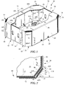
- Article-transport container 10 includes four tri-layer corners 21, 22, 23, 24 in accordance with a first embodiment of the present disclosure and first tri-layered corner 21 is shown in Fig. 2 .
- Article-transport container 10 includes, in series starting in the front left, a front end wall 12 coupled to a floor 14 included in container 10, a left side closure 16 coupled to floor 14 and including a left canopy 70L overlying floor 14, a rear end wall 18 coupled to floor 14, and a right side closure 20 coupled to floor 14 and including a right canopy 70 overlying floor 14.
- Front end wall 12, left side closure 16, rear end wall 18, right side closure 20, floor 14, and tri-layer corners 21, 22, 23, 24 cooperate to define an interior region 26 therebetween that is adapted to receive articles (not shown) therein.
- Another embodiment of a tri-layer corner 221A is shown in Figs. 10-12 .
- Tri-layer corners 21, 22, 23, 24 cooperate to provide means for increasing stack strength of container 10 while simplifying blank forming and minimizing scrap produced during blank forming.
- first tri-layer corner 21 includes an outer layer 211, a medial layer 212, and an inner layer 213 as shown in Fig. 2 .
- Medial layer 212 is positioned to lie between outer layer 211 and inner layer 213 and is configured to provide means for interconnecting outer layer 211 and inner layer 213 to cause stack strength of container 10 to be improved while minimizing scrap produced during blank forming so that costs associated with producing container 10 are minimized.
- Container 10 is made from a blank 28 after blank 28 is formed in a blank-forming process.
- blank 28 includes floor 14, left side closure 16 appended to floor 14 along a left-side fold line 30, right side closure 20 appended to floor 14 along a right-side fold line 32, rear end wall 18 appended to floor 14 along a rear-end fold line 34, and front end wall 12 appended to floor 14 along a front-end fold line 36.
- Right side closure 20, left side closure 16, rear end wall 18, front end wall 12, and tri-layer corners 21, 22, 23, 24 cooperate to form a border coupled to floor 14 and arranged to cooperate with floor 14 to define interior region 26 of container 10.
- Rear end wall 18 cooperates with left side closure 16 and right side closure 20 to establish a rear end 38 of container 10 as shown in Fig. 1 .
- Front end wall 12 cooperates with left side closure 16 and right side closure 20 to establish a front end 40 of container 10 as shown in Fig. 1 . It is within the scope of the present disclosure to make blank 28 from a variety of materials including corrugated paperboard, folding carton, and solid fiber and other materials such as plastic sheeting and corrugated plastic.
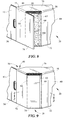
- Article-transport container 10 is established as result of passing blank 28 through a container-forming process shown, for example, in Figs. 4-9 .
- blank 28 includes floor 14, a front end strip 42 coupled to floor 14 along front-end fold line 36, left side closure 16 coupled to floor 14 along left-side fold line 30, a rear end strip 44 coupled to floor 14 along rear-end fold line 34, and right side closure 20 coupled to floor 14 along right-side fold line 32 as shown in Fig. 4 .
- Front end strip 42 illustratively includes front end wall 12, a first front anchor flap 46 coupled to front end wall 12 about a first front anchor-flap fold line 48, and a second front anchor flap 50 coupled to front end wall 12 about a second front anchor-flap fold line 52 as shown in Fig. 3 .
- First front anchor flap 46 is positioned to lie in spaced-apart relation to second front anchor flap 50 to locate front end wall 12 therebetween. As shown in Figs. 2 and 6 , a portion of first front anchor flap 46 is used to establish inner layer 213 of first tri-layer corner 21. Similarly, a portion of second front anchor flap 50 is used to establish inner layer 223 of second tri-layer corner 22.
- First front anchor flap 46 includes a front right corner bridge 90 that is coupled to front end wall 12 about a first front anchor-flap fold line 48 and a front right anchor tab 94 that is coupled to front right corner bridge 90 about a first front anchor-tab fold line 96 as shown in Fig. 3 .
- Inner layer 213 of first tri-layer corner 21 is established during an intial stage of container forming as suggested in Figs. 4-9 .
- front end strip 42 is folded about front-end fold line 36 toward floor 14.
- front right corner bridge 90 is folded inwardly toward floor 14 about first front anchor-flap fold line 48 and front right anchor tab 94 is folded inwardly toward floor 14 about first front anchor-tab fold line 96.
- front end strip 42 is arranged to extend upwardly away from floor 14 and front right anchor tab 94 is arranged to extend along right-side fold line 32.
- Front right corner bridge 90 is arranged to extend between and interconnect front right anchor tab 94 and front end wall 12.
- Right side closure 20 illustratively includes a right inner strip 54 coupled to floor 14 about right-side fold line 32 and a right outer anchor strip 56 coupled to right inner strip 54 about a right anchor-strip fold line 58 as shown in Fig. 3 .
- Right inner strip 54 includes, for example, a right side wall 60, a first right wall anchor flap 62 coupled to right side wall 60 about a first right wall flap fold line 64, and a second right wall anchor flap 66 coupled to right side wall 60 about a second right wall flap fold line 68 as shown in Fig. 3 .
- First right wall anchor flap 62 is used to establish medial layer 212 of first tri-layer corner 21. Medial layer 212 of first tri-layer corner 21 is established during a subsequent stage of container forming as suggested in Figs. 4-9 .
- right side closure 20 is folded about right-side fold line 32 toward floor 14 so that right side wall 60 and first and second right wall anchor flap 62, 66 extend upwardly away from floor 14 as shown in Fig. 5 .
- first and second right wall anchor flaps 62, 66 are folded inwardly toward floor 14 about associated right wall flap fold lines 64, 68.
- first right wall anchor flap 62 is arranged to extend away from right side wall 60 toward front end wall 12 and is coupled to front right corner bridge 90 and form medial layer 212 as shown in Figs. 2 and 7 .
- Right outer anchor strip 56 includes a right canopy 70, a first right primary canopy anchor flap 72, a first right auxiliary canopy anchor flap 74, a second right primary canopy anchor flap 76, and a second right auxiliary canopy anchor flap 78 as shown in Fig. 3 .
- Right canopy 70 is coupled to right side wall 60 about right anchor-strip fold line 58.
- First right primary canopy anchor flap 72 is coupled to right canopy 70 by a first right primary flap fold line 80.
- First right auxiliary canopy anchor flap 74 is coupled to first right primary canopy anchor flap 72 by a first right auxiliary flap fold line 84 as shown in Fig. 3 .
- Second right primary canopy anchor flap 76 is coupled to right canopy 70 by a second right primary flap fold line 86.
- Second right auxiliary canopy anchor flap 78 is coupled to second right primary canopy anchor flap 76 by a first right auxiliary flap fold line 88 as shown in Fig. 3 .
- Outer layer 211 of first tri-layer corner 21 is established during a last stage of container forming as suggested in Figs. 8 and 9 .
- right outer anchor strip 56 is folded about right anchor-strip fold line toward floor 14 so that right canopy 70 is arranged to lie in spaced-apart parallel relation above floor 14 as shown in Fig. 2 .
- first right primary and auxiliary canopy anchor flaps 72, 74 are folded downwardly about first right primary flap fold line 80 so that first right primary canopy anchor flap 72 extends downwardly and mates with front end wall 12 as suggested in Fig. 7 and shown in Fig. 8 .
- first tri-layer corner 21 is established as a result of folding first right auxiliary canopy anchor flap 74 about first right auxiliary flap fold line 84 toward first right wall anchor flap 62 as suggested in Fig. 8 and shown in Fig. 9 .
- First tri-layer corner 21 is established as a result of coupling first right wall anchor flap 62 to front right corner bridge 90 and by coupling first right auxiliary canopy anchor flap 74 to first right wall anchor flap 62 as shown in Figs. 6-9 .
- first right wall anchor flap 62 is coupled to front right corner bridge 90 by adhesive 98 as shown in Fig. 6 .
- First right auxiliary canopy anchor flap 74 is coupled to first right wall anchor flap 62 by adhesive 100 as shown in Figs. 7 and 8 . While adhesive 98, 100 is shown as an example, any other suitable alternative may be used.
- the corrugation of blank 28 is positioned to run in a transverse direction TD as shown in insert A in Figs. 1 , 3 , and 4 .
- inner and outer layers 211, 213 of tri-layer corners 21, 22, 23, 24 have corrugation which runs vertically as shown in Fig. 6 after container 10 has been formed.
- Medial layer 212 has corrugation which runs horizontally as shown in Fig. 6 after container 10 has been formed.
- Stacking strength may be measured using standard industry test methods. As an example, stacking strength was evaluated using the TSL-8.2-WI-005 test method and procedure reference T804 of the Technical Association of the Pulp and Paper Industry (TAPPI).
- floor 14 has an octagon shape that includes in series, a first mitered edge 102, a front end edge 104, a second mitered edge 106, a left edge 108, a third mitered edge 110, a rear end edge 112, a fourth mitered edge 114, and a right edge 116.
- left and right edges 108, 116 have lengths greater than lengths of front and rear end edges 104, 112.
- Front and rear end edges 104, 112 have lengths greater than first, second, third, and fourth mitered edges 102, 106, 110, 114.
- Edges 102, 104, 106, 108, 110, 112, 114 cooperate to define a floor perimeter 92 as shown in Fig. 3 .
- First tri-layer corner 21 is arranged to extend between front end wall 12 and right side wall 60 and lie at an angle 118 relative to front end wall 12 as shown in Fig. 2 .
- Angle 118 is defined to be between first mitered edge 102 of floor 14 and front end edge 104 of floor 14. As shown in Fig. 2 , angle 118 is illustratively an acute angle.
- Inner layer 213 of tri-layer corner 21 is positioned to lie inside floor perimeter 92 and is arranged to extend between front end edge 104 and right edge 116 and between floor 14 and right canopy 70.
- Medial layer 212 is positioned to lie outside floor perimeter 92 is and is arranged to extend along first mitered edge 102 so that medial layer 212 lies at angle 118.
- Outer layer 211 is positioned to lie outside floor perimeter 92 and is arranged to lie in spaced-apart relation to first mitered edge 102 to cause medial layer 212 to lie there between.
- Blank 28 is formed during an illustrative blank forming process, for example in a manufacturing facility.
- a corrugated sheet is processed to establish blank 28 and scrap which separated from blank 28.
- first right wall anchor flap 62 is formed to have a proximal end 62P and a distal end 62D which is spaced-apart from proximal end 62P.
- First right wall anchor flap 62 is appended to right side wall 60 along first right wall flap fold line 64 by proximal end 62P. As shown in Fig.
- first right wall anchor flap 62 extends away from first right wall flap fold line 64 toward first front anchor flap 46 and first right auxiliary canopy anchor flap 74 such that distal end 62D is spaced apart from first front anchor flap 46 and first right auxiliary canopy anchor flap 74.
- scrap is separated from blank 28 which causes two triangle-shaped apertures 120A, 120B and an interconnecting rectangle-shaped aperture 120C to be formed therein.
- the scrap piece being monolithic, it simplifies removal and separation from blank 28.
- distal end 62D being spaced apart from first front anchor flap 46 and first right auxiliary canopy anchor flap 74 is that rectangle-shaped aperture 120C is formed by removing scrap.
- Container forming is simplified as a result of distal end 62D of first right wall anchor flap 62 being spaced-apart from first front anchor flap 46 and first right auxiliary canopy anchor flap 74 is that friction between distal end 62D of and first front anchor flap 46 and first right auxiliary canopy anchor flap 74 is eliminated. Because friction has been eliminated, the likelihood of forming improperly formed containers is minimized.
- First crush area 121 is configured to provide means for minimizing friction developed between front right anchor tab 94 and first right auxiliary canopy anchor flap 74 during container forming as front right anchor tab 94 of front end strip 42 is folded upwardly about front-end fold line 36.
- Second, third, and fourth crush areas 122, 123, 124 are also formed.
- First, second, third, and fourth crush areas 122, 123, 124 are substantially similar to first crush area 121, and thus, only first crush area 121 will be discussed in detail.
- First crush area 121 is established along a cut line 125 formed between front right anchor tab 94 and first right auxiliary canopy anchor flap 74 as shown in Fig. 3 .
- a rate of container forming may be increased as a result of minimizing friction which decreases the likelihood of improperly forming containers. These improperly formed containers are also called as cripples.
- Blank 28 and resulting container 10 minimize waste because the number of improperly formed containers is minimized.
- Second tri-layer corner 22 is formed during container forming by folding front end strip 42 and left side closure 16 so that second tri-layer corner 22 is established as a result as suggested in Figs. 4 and 5 .
- a portion of second front anchor flap 50 establishes an inner layer 223 of second tri-layer corner 22.
- Second front anchor flap 50 includes a front left corner bridge 90L that is coupled to front end wall 12 about a second front anchor-flap fold line 52 and a front left anchor tab 94L that is coupled to front left corner bridge 90L about a second front anchor-tab fold line 96L as shown in Fig. 3 .
- Inner layer 223 of second tri-layer corner 22 is established during an intial stage of container forming as suggested in Figs. 4 and 5 .
- front end strip 42 is folded about front-end fold line 36 toward floor 14.
- front left corner bridge 90L is folded inwardly toward floor 14 about second front anchor-flap fold line 52 and front right anchor tab 94L is folded inwardly toward floor 14 about second front anchor-tab fold line 96L.
- front end strip 42 is arranged to extend upwardly away from floor 14 and front left anchor tab 94L is arranged to extend along left-side fold line 30.
- Front left corner bridge 90L is arranged to extend between and interconnect front left anchor tab 94L and front end wall 12.
- Left side closure 16 illustratively includes a left inner strip 54L coupled to floor 14 about left-side fold line 30 and a left outer anchor strip 56L coupled to left inner strip 54L about a left anchor-strip fold line 58L as shown in Fig. 3 .
- Left inner strip 54L includes, for example, a left side wall 60L, a first left wall anchor flap 62L coupled to left side wall 60L about a first left wall flap fold line 64L, and a second left wall anchor flap 66L coupled to left side wall 60L about a second left wall flap fold line 68L as shown in Fig. 3 .
- First left wall anchor flap 62L establishes medial layer 222 of second tri-layer corner 22. Medial layer 222 of second tri-layer corner 22 is established during the subsequent stage of container forming.
- left side closure 16 is folded about left-side fold line 30 toward floor 14 so that left side wall 60L and first and second left wall anchor flaps 62L, 66L extend upwardly away from floor 14 as shown in Fig. 5 .
- first and second left wall anchor flaps 62L, 66L are folded inwardly toward floor 14 about associated left wall flap fold lines 64L, 68L.
- first left wall anchor flap 62L is arranged to extend away from left side wall 60L toward front end wall 12 and is coupled to front left corner bridge 90L and form medial layer 222.
- Left outer anchor strip 56L includes a left canopy 70L, a first left primary canopy anchor flap 72L, a first left auxiliary canopy anchor flap 74L, a second left primary canopy anchor flap 76L, and a second left auxiliary canopy anchor flap 78L as shown in Fig. 3 .
- Left canopy 70L is coupled to left side wall 60L about left anchor-strip fold line 58L.
- First left primary canopy anchor flap 72L is coupled to left canopy 70L by a first left primary flap fold line 80L.
- First left auxiliary canopy anchor flap 74L is coupled to first left primary canopy anchor flap 72L by a first left auxiliary flap fold line 84L as shown in Fig. 3 .
- Second left primary canopy anchor flap 76L is coupled to left canopy 70L by a second left primary flap fold line 86L.
- Second left auxiliary canopy anchor flap 78L is coupled to second left primary canopy anchor flap 76L by a first left auxiliary flap fold line 88L as shown in Fig. 3 .
- Outer layer 221 of second tri-layer corner 22 is established during the last stage of container forming.
- left outer anchor strip 56L is folded about left anchor-strip fold line 58L toward floor 14 so that left canopy 70L is arranged to lie in spaced-apart parallel relation to floor 14.
- first left primary and auxiliary canopy anchor flaps 72L, 74L are folded downwardly about first left primary flap fold line 80L so that first left primary canopy anchor flap 72L extends downwardly and mates with front end wall 12.
- second tri-layer corner 22 is established as a result of folding first left auxiliary canopy anchor flap 74L about first left auxiliary flap fold line 84L toward first left wall anchor flap 62L.
- Second tri-layer corner 22 is established as a result of coupling first left wall anchor flap 62L to front left corner bridge 90L and by coupling first left auxiliary canopy anchor flap 74L to first left wall anchor flap 62L.
- first left wall anchor flap 62L is coupled to front left corner bridge 90L by adhesive and first left auxiliary canopy anchor flap 74L is coupled to front left corner bridge 90L by adhesive.
- Third tri-layer corner 23 is formed during container forming by folding front end strip 42 and left side closure 16 so that third tri-layer corner 23 is established as a result as suggested in Figs. 4 and 5 .
- a portion of rear end strip 44 establishes an inner layer 233 of third tri-layer corner 23.
- Rear end strip 44 illustratively includes rear end wall 18, a first rear anchor flap 46R coupled to rear end wall 18 about a first rear anchor-flap fold line 48R, and a second rear anchor flap 50R coupled to rear end wall 18 about a second rear anchor-flap fold line 52R as shown in Fig. 3 .
- First rear anchor flap 46R is positioned to lie in spaced-apart relation to second rear anchor flap 50R to locate rear end wall 18 therebetween.
- a portion of first rear anchor flap 46R is used to establish inner layer 233 of third tri-layer corner 23.
- second rear anchor flap 50R is used to establish inner layer 243 of fourth tri-layer corner 24.
- First rear anchor flap 46R includes a rear left corner bridge 126 that is coupled to rear end wall 18 about a first rear anchor-flap fold line 48R and a rear left anchor tab 130 that is coupled to rear left corner bridge 126 about a first rear anchor-tab fold line 132 as shown in Fig. 3 .
- Inner layer 233 of third tri-layer corner 23 is established during the intial stage of container forming as suggested in Figs. 4 and 5 .
- rear end strip 44 is folded about rear-end fold line 34 toward floor 14.
- rear left corner bridge 126 is folded inwardly toward floor 14 about first rear anchor-flap fold line 48R and rear left anchor tab 130 is folded inwardly toward floor 14 about first rear anchor-tab fold line 132.
- rear end strip 44 is arranged to extend upwardly away from floor 14 and rear left anchor tab 130 is arranged to extend along left-side fold line 30.
- Rear left corner bridge 126 is arranged to extend between and interconnect rear left anchor tab 130 and rear end wall 18.
- left side closure 16 is folded about left-side fold line 30 toward floor 14 so that left side wall 60L and first and second left wall anchor flap 62L, 66L extend upwardly away from floor 14 as shown in Fig. 5 .
- first and second left wall anchor flaps 62L, 66L are folded inwardly toward floor 14 about associated left wall flap fold lines 64L, 68L.
- second left wall anchor flap 66L is arranged to extend away from left side wall 60L toward rear end wall 18 and is coupled to rear left corner bridge 126 to form medial layer 232.
- left outer anchor strip 56L is folded about left anchor-strip fold line 58L toward floor 14 so that left canopy 70L is arranged to lie in spaced-apart parallel relation to floor 14 as shown in Fig. 2 .
- second left primary and auxiliary canopy anchor flaps 76L, 78L are folded downwardly about second left primary flap fold line 86L so that second left primary canopy anchor flap 76L extends downwardly and mates with rear end wall 18.
- third tri-layer corner 23 is established as a result of folding second left auxiliary canopy anchor flap 78L about second left auxiliary flap fold line 88L toward second left wall anchor flap 62L.
- Third tri-layer corner 23 is established as a result of coupling second left wall anchor flap 66L to rear left corner bridge 126 and by coupling second left auxiliary canopy anchor flap 78L to rear left corner bridge 126.
- second left wall anchor flap 66L is coupled to rear left corner bridge 126 by adhesive and second left auxiliary canopy anchor flap 78L is coupled to rear left corner bridge 126 by adhesive.
- Fourth tri-layer corner 24 is formed during container forming by folding rear end strip 44 and right side closure 20 so that fourth tri-layer corner 24 is established as a result as suggested in Figs. 4 and 5 .
- a portion of second rear anchor flap 50R establishes inner layer 243 of fourth tri-layer corner 24.
- Second rear anchor flap 50R includes a rear right corner bridge 134 that is coupled to rear end wall 18 about a second rear anchor-flap fold line 52R and a rear right anchor tab 138 that is coupled to rear right corner bridge 134 about a second rear anchor-tab fold line 140 as shown in Fig. 3 .
- Inner layer 243 of fourth tri-layer corner 24 is established during the intial stage of container forming as suggested in Figs. 4 and 5 .
- rear end strip 44 is folded about rear-end fold line 34 toward floor 14.
- rear right corner bridge 134 is folded inwardly toward floor 14 about second rear anchor-flap fold line 52R and rear right anchor tab 138 is folded inwardly toward floor 14 about second rear anchor-tab fold line 140.
- rear end strip 44 is arranged to extend upwardly away from floor 14 and rear right anchor tab 138 is arranged to extend along right-side fold line 32.
- Rear right corner bridge 134 is arranged to extend between and interconnect rear right anchor tab 138 and rear end wall 18.
- right side closure 20 is folded about right-side fold line 32 toward floor 14 so that right side wall 60 and first and second right wall anchor flap 62, 66 extend upwardly away from floor 14 as shown in Fig. 5 .
- first and second right wall anchor flaps 62, 66 are folded inwardly toward floor 14 about associated right wall flap fold lines 64, 68.
- second right wall anchor flap 68 is arranged to extend away from right side wall 60 toward rear end wall 18 and is coupled to rear right corner bridge 134 and form medial layer 242.
- right outer anchor strip 56 is folded about right anchor-strip fold line 58 toward floor 14 so that right canopy 70 is arranged to lie in spaced-apart parallel relation to floor 14 as shown in Fig. 2 .
- second right primary and auxiliary canopy anchor flaps 76, 78 are folded downwardly about second right primary flap fold line 86 so that second right primary canopy anchor flap 76 extends downwardly and mates with rear end wall 18.
- fourth tri-layer corner 24 is established as a result of folding second right auxiliary canopy anchor flap 78 about second right auxiliary flap fold line 88 toward second right wall anchor flap 66.
- Fourth tri-layer corner 24 is established as a result of coupling second right wall anchor flap 66 to rear right corner bridge 134 and by coupling second right auxiliary canopy anchor flap 78 to rear right corner bridge 134.
- second right wall anchor flap 66 is coupled to rear right corner bridge 134 by adhesive and second right auxiliary canopy anchor flap 78 is coupled to rear right corner bridge 134 by adhesive.
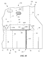
- FIG. 10 A portion of a blank 218 of corrugated material in accordance with a second embodiment of the present disclosure is shown in Fig. 10 and can be assembled as suggested in Fig. 10 to produce a first tri-layer corner 221A of a container 210 as shown in Fig. 12 .
- blank 218 is similar to blank 28 of Fig. 3 .
- Blank 218 includes floor 14, a right side closure 220 appended to floor 14 along right-side fold line 32, and a front end strip 42 appended to floor 14 along front-end fold line 36 as shown in Fig. 10 .
- Right side closure 220 and front end strip 42 are configured to be folded in a manner similar to that shown in Figs. 4-9 to produce first tri-layer corner 221A.
- first tri-layer corner 221A includes outer layer 211, a medial layer 2212, and inner layer 213 as shown in Figs. 11 and 12 .
- Inner layer 213 is provided by front right corner bridge 90 of front end strip 42 and is established during initial folding of blank 218.
- Medial layer 2212 is provided by a first right wall anchor flap 262 included in right side closure 220 and is established during the subsequent folding of blank 218.
- Outer layer 211 is provided by first right auxiliary canopy anchor flap 74 and is established during the final folding of blank 218.
- Right side closure 220 illustratively includes a right inner strip 254 coupled to floor 14 about right-side fold line 32 and right outer anchor strip 56 coupled to right inner strip 254 about right anchor-strip fold line 58 as shown in Fig. 10 .
- Right inner strip 254 includes, for example, right side wall 60, a first right wall anchor flap 262 coupled to right side wall 60 about first right wall flap fold line 64, and a second right wall anchor flap (not shown) coupled to right side wall 60 about second right wall flap fold line (not shown).
- First right wall anchor flap 262 establishes medial layer 2212 of first tri-layer corner 221A. Medial layer 2212 of first tri-layer corner 221A is established during the subsequent stage of container 210 in a manner similar to that of container 10 suggested in Figs. 4-9 .
- Blank 218 is formed during an illustrative blank forming process in which a corrugated sheet is processed to establish blank 218 and scrap which is separated from blank 218.
- first right wall anchor flap 262 is formed to have a proximal end 262P and a distal end 262D which is spaced-apart from proximal end 262P.
- First right wall anchor flap 262 is appended to right side wall 60 along first right wall flap fold line 64 by proximal end 262P. As shown in Fig.
- first right wall anchor flap 262 extends away from first right wall flap fold line 64 toward first front anchor flap 46 and first right auxiliary canopy anchor flap 74 such that distal end 262D abuts first front anchor flap 46 and first right auxiliary canopy anchor flap 74. Distal end 262D is separated from first front anchor flap 46 and first right auxiliary canopy anchor flap 74 by a cut line 142 as shown in Fig. 10 .
- a first right-wall anchor-flap crush area 144 which is established during blank forming to provide means for minimizing friction developed between first right wall anchor flap 262 and first front anchor flap 46 and first right auxiliary canopy anchor flap 74 during container forming so that the likelihood of creating improperly formed containers is minimized.
- the corrugation of blank 218 is positioned to run in a transverse direction TD as shown in insert 2A in Fig. 10 .
- inner and outer layers 211, 213 of tri-layer corner 221A has corrugation which runs vertically as shown in Fig. 12 after container 210 has been formed.
- Medial layer 2212 has corrugation which runs horizontally as shown in Fig. 10 after container 10 has been formed.
- it was found surprisingly that the medial layer 2212 of tri-layer corner 221A increases stacking strength of container 210 about 7%.
- Stacking strength may be measured using standard industry test methods. As an example, stacking strength was evaluated using the TSL-8.2-WI-005 test method and procedure reference T804 of the Technical Association of the Pulp and Paper Industry (TAPPI).
- the right canopy and the left canopy may be configured so as to establish a lid after the container has been formed.
- the right canopy has a width about equal to one half a width of the floor and the left canopy has a width about equal to one half the width of the floor.
- the right canopy is folded inwardly toward the floor about the right anchor-strip fold line so that the right canopy lies above the floor and extends away from the right side wall toward the left sidewall.
- the left canopy is also folded inwardly toward the floor about the left anchor-strip fold line so that the left canopy lies above the floor and extends away from the left side wall toward the right side wall.
- the interior region is defined by the floor, the right side closure, the left side closure, the front end wall, the rear end wall, the four tri-layer corners, and the lid established upon completion of forming the container.
- a container further includes a front canopy and a rear canopy.
- the front canopy is coupled to the front end wall about a front-canopy fold line.
- the rear canopy is coupled to the rear end wall about a rear-canopy fold line.
- the front canopy lies in a plane positioned to lie between the right canopy and the floor.
- the rear canopy lies in a plane that is positioned to lie between the left canopy and the floor. The rear canopy, front canopy, left canopy, and right canopy cooperate to establish a framed top of the container.
Landscapes
- Engineering & Computer Science (AREA)
- Mechanical Engineering (AREA)
- Cartons (AREA)
- Refuse Receptacles (AREA)
- Accommodation For Nursing Or Treatment Tables (AREA)
- Medical Preparation Storing Or Oral Administration Devices (AREA)
Claims (4)
- Gegenstand-Transportbehälter, umfassend:einen Boden (14) mit einem jeweils faltbar daran angefügten linksseitigen und rechtsseitigen Verschluss (16, 20, 220), eine Vorderdseitenwand (12), die faltbar an den Boden (14) und jeweils den linksseitigen und den rechtsseitigen Verschluss (16, 20, 220) angefügt ist, eine Rückseitenwand (18), die faltbar an den Boden (14) und jeweils den linksseitigen und den rechtsseitigen Verschluss (16, 20, 220) angefügt ist, und vier Dreierschichtecken (21, 22, 23, 24, 221A), die durch eine erste Dreierschichtecke, eine zweite Dreierschichtecke, eine dritte Dreierschichtecke und eine vierte Dreierschichtecke definiert sind, die mit jeweils dem linksseitigen und dem rechtsseitigen Verschluss zusammenwirken, um einen Innenbereich zu definieren, der dafür eingerichtet ist, Gegenstände in sich aufzunehmen, dadurch gekennzeichnet, dass die erste Dreierschichtecke (221A) durch Koppeln einer ersten rechtswandigen Verankerungszunge (62, 262) mit einer vorderen rechten Eckbrücke (90) und durch Koppeln einer ersten rechten Hilfskopfblenden-Verankerungszunge (74) mit der ersten rechtswandigen Verankerungszunge (62, 262) gebildet wird.
- Behälter nach Anspruch 1, wobei die erste, die zweite, die dritte und die vierte Dreierschichtecke (21, 22, 23, 24, 221A) jeweils eine Außen- und eine Innenschicht (211, 213) und Mittelschicht (2212) beinhaltet, die zwischen die jeweilige Außen- und Innenschicht eingesetzt ist, um die Stapelfestigkeit des Behälters zu erhöhen, während die Produktion von Abfällen während der Errichtung des Behälters minimiert wird, oder wobei die Innenschicht (213) durch eine vordere rechte Eckbrücke (90) eines Vorderseitenstreifens (42) während des ersten Faltens bereitgestellt wird, die Mittelschicht (2212) durch eine im rechtsseitigen Verschluss (220) enthaltene erste rechtswandige Verankerungszunge (262) während des anschließenden Faltens bereitgestellt wird und die Außenschicht (24) durch eine erste rechte Hilfskopfblenden-Verankerungszunge (74) bereitgestellt wird und während des letzten Faltens hergestellt wird.
- Rohling (218) zum Herstellen eines Gegenstand-Transportbehälters, Folgendes umfassend:einen Boden (14), einen rechtsseitigen Verschluss (220), der entlang einer rechtsseitigen Faltlinie (32) dem Boden (14) anhängt, und einen Vorderseitenstreifen (42), der entlang einer Vorderseiten-Faltlinie (36) dem Boden (14) anhängt, wobei der Vorderseitenverschluss (220) und der Vorderseitenstreifen (42) dafür gestaltet sind, gefaltet zu werden, um eine erste Dreierschichtecke (221A) zu erzeugen, die erste Dreierschichtecke (221A) eine Außenschicht (211), eine Mittelschicht (2212) und eine Innenschicht (213) beinhaltet, wobei die Innenschicht (213) durch eine vordere rechte Eckbrücke (90) des Vorderseitenstreifens (42) bereitgestellt wird und während des ersten Faltens des Rohlings (218) hergestellt wird, wobei die Mittelschicht (2212) durch eine erste rechtswandige Verankerungszunge (262) bereitgestellt wird, die im rechtsseitigen Verschluss (220) enthalten ist, und während des anschließenden Faltens des Rohlings (218) hergestellt wird, und die Außenschicht (211) durch eine erste rechte Hilfskopfblenden-Verankerungszunge (74) bereitgestellt wird und während des letzten Faltens des Rohling (218) hergestellt wird.
- Rohling (218) nach Anspruch 3, wobei ein Stück von dem Rohling (218) entfernt wird, was bewirkt, dass zwei dreieckige Öffnungen (120A), (120B) in diesem gebildet werden, ohne eine verbindende rechteckige Öffnung (120C).
Applications Claiming Priority (2)
| Application Number | Priority Date | Filing Date | Title |
|---|---|---|---|
| US201261590227P | 2012-01-24 | 2012-01-24 | |
| PCT/US2013/021898 WO2013112348A1 (en) | 2012-01-24 | 2013-01-17 | Article-transport container |
Publications (2)
| Publication Number | Publication Date |
|---|---|
| EP2807083A1 EP2807083A1 (de) | 2014-12-03 |
| EP2807083B1 true EP2807083B1 (de) | 2016-10-26 |
Family
ID=47666499
Family Applications (1)
| Application Number | Title | Priority Date | Filing Date |
|---|---|---|---|
| EP13702853.6A Active EP2807083B1 (de) | 2012-01-24 | 2013-01-17 | Artikeltransportbehälter und artikeltransportbehälterzuschnitt |
Country Status (10)
| Country | Link |
|---|---|
| US (1) | US9126711B2 (de) |
| EP (1) | EP2807083B1 (de) |
| AR (1) | AR089636A1 (de) |
| BR (1) | BR112014018100B1 (de) |
| CA (1) | CA2861907C (de) |
| ES (1) | ES2613304T3 (de) |
| MA (1) | MA35876B1 (de) |
| MX (1) | MX350458B (de) |
| PE (1) | PE20142171A1 (de) |
| WO (1) | WO2013112348A1 (de) |
Families Citing this family (16)
| Publication number | Priority date | Publication date | Assignee | Title |
|---|---|---|---|---|
| US8864017B2 (en) | 2011-10-13 | 2014-10-21 | Orbis Corporation | Plastic corrugated container with improved fold lines and method and apparatus for making same |
| WO2013072866A1 (en) * | 2011-11-18 | 2013-05-23 | Stephanus Petrus De Beer | Stackable open topped box |
| AR089636A1 (es) | 2012-01-24 | 2014-09-03 | Tin Inc | Contenedor para transportar articulos |
| AR092668A1 (es) | 2012-09-26 | 2015-04-29 | Tin Inc | Contenedor para transporte de productos |
| WO2015100249A2 (en) | 2013-12-24 | 2015-07-02 | Orbis Corporation | Plastic corrugated container and manufacturing process |
| US10829265B2 (en) | 2013-12-24 | 2020-11-10 | Orbis Corporation | Straight consistent body scores on plastic corrugated boxes and a process for making same |
| US10625916B2 (en) | 2013-12-24 | 2020-04-21 | Orbis Corporation | Plastic corrugated container with soft score line |
| US11643242B2 (en) | 2013-12-24 | 2023-05-09 | Orbis Corporation | Air vent for welded portion in plastic corrugated material, and process for forming welded portion |
| US9938038B2 (en) * | 2014-02-05 | 2018-04-10 | Menasha Corporation | Shipping and display containers and methods of making same |
| AU2014385940B2 (en) * | 2014-03-14 | 2019-05-23 | Rengo Co., Ltd. | Packing box and box manufacturing apparatus |
| USD772068S1 (en) * | 2015-04-30 | 2016-11-22 | SZ DJI Technology Co., Ltd | Packaging |
| MX2019009912A (es) | 2017-02-21 | 2019-10-14 | Menasha Corp | Marcas estructurales rectas uniformes en cajas de plastico corrugado y un proceso para hacer las mismas. |
| USD867875S1 (en) * | 2017-05-10 | 2019-11-26 | Mutty Greenfeld | Box |
| US11072140B2 (en) | 2017-06-20 | 2021-07-27 | Orbis Corporation | Balanced process for extrusion of plastic corrugated sheet and subsequent converting into plastic boxes |
| WO2021113735A1 (en) * | 2019-12-05 | 2021-06-10 | Westrock Shared Services, Llc | Non-rectangular carton |
| JP7444020B2 (ja) * | 2020-10-21 | 2024-03-06 | 王子ホールディングス株式会社 | トレイ |
Family Cites Families (57)
| Publication number | Priority date | Publication date | Assignee | Title |
|---|---|---|---|---|
| US667112A (en) | 1900-06-05 | 1901-01-29 | Alexander W Beers | Folding or collapsible box. |
| US2147563A (en) * | 1937-12-14 | 1939-02-14 | O B Andrews Company | Octagonal box |
| US2603404A (en) | 1949-09-20 | 1952-07-15 | Robert L Eldredge | Carton |
| US2868430A (en) | 1956-08-07 | 1959-01-13 | Container Corp | Stacking paperboard tray |
| US3118591A (en) | 1960-04-30 | 1964-01-21 | Sarl Allard & Fils | Cardboard tray for fruit |
| GB971565A (en) * | 1962-04-06 | 1964-09-30 | Wovit Containers Ltd | Improvements in and relating to trays and the like of corrugated paper or the like |
| DE1302131B (de) | 1963-06-11 | 1970-01-15 | ||
| US3310219A (en) | 1965-06-02 | 1967-03-21 | Container Corp | Heavy duty container with integral handle |
| US3545666A (en) | 1968-10-14 | 1970-12-08 | Container Corp | Container having corner post for top to bottom stacking |
| US3704823A (en) | 1969-12-08 | 1972-12-05 | Georgia Pacific Corp | Open-top stacking carton and blank therefor |
| US3810574A (en) | 1972-10-16 | 1974-05-14 | Container Corp | Self-locking tray |
| US3871570A (en) | 1973-04-02 | 1975-03-18 | Hoerner Waldorf Corp | Shipping tray |
| US4537344A (en) | 1982-03-11 | 1985-08-27 | International Paper Company | Interlocking corner structure on tray for frozen fruits and vegetables |
| GB8407378D0 (en) * | 1984-03-21 | 1984-04-26 | Omergo Lodge Ltd | Boxes and blanks |
| US4613045A (en) | 1985-08-29 | 1986-09-23 | Weyerhaeuser Company | Bulk shipping container |
| US4792084A (en) | 1986-02-24 | 1988-12-20 | Longview Fibre Company | Paperboard container with angled corners |
| GB8904840D0 (en) | 1989-03-03 | 1989-04-12 | Tarleton Box Company Limited | Boxes |
| US4883221A (en) | 1989-04-28 | 1989-11-28 | Stone Container Corporation | Carton tray apparatus |
| US5052615A (en) | 1989-05-25 | 1991-10-01 | Restaurant Technology, Inc. | Food carton and method |
| US4911355A (en) | 1989-06-19 | 1990-03-27 | James Bannister | Foldable carton |
| US5016814A (en) * | 1990-09-19 | 1991-05-21 | Fullerton James T | Collapsible box with improved corner locks |
| FR2669301B1 (fr) | 1990-11-21 | 1994-07-08 | Emballages Ste Mediterraneenne | Emballage pour fruits et legumes. |
| US5163609A (en) | 1991-06-27 | 1992-11-17 | Weyerhaeuser Company | Produce container |
| FR2687634B1 (fr) | 1992-02-20 | 1994-05-13 | Otor | Procede et flan pour la realisation d'une caisse autour d'une charge, et caisse ainsi obtenue. |
| US5289970A (en) | 1992-10-02 | 1994-03-01 | Inland Container Corporation | Paperboard container having reinforced corners |
| US5330094A (en) | 1993-12-16 | 1994-07-19 | Jefferson Smurfit Corporation | Stackable display tray |
| US5560539A (en) | 1994-01-31 | 1996-10-01 | The Mead Corporation | Sealable carton |
| GB9506287D0 (en) * | 1995-03-28 | 1995-05-17 | Bpb Industries Plc | Box |
| GB2310197B (en) * | 1996-02-13 | 2000-02-02 | Bpb Industries Plc | A box |
| US5752648A (en) | 1996-06-19 | 1998-05-19 | International Paper | Web bottomed eight sided tray |
| US5853120A (en) | 1996-07-31 | 1998-12-29 | Stone Container Corporation | Tray apparatus with reinforced corner structure |
| US5913474A (en) * | 1997-10-10 | 1999-06-22 | Merryland Products, Inc. | Foldable tote box |
| US6394742B1 (en) | 1999-04-30 | 2002-05-28 | The Mead Corporation | Method for stacking boxes and removal of individual boxes from the stack |
| US6513705B1 (en) | 1999-05-07 | 2003-02-04 | Pack ‘N’ Stack | Fold and glue stacking container with side access |
| US6302323B1 (en) | 1999-10-22 | 2001-10-16 | Packaging Corporation Of America | Displayable produce container and method for making the same |
| US6286753B1 (en) * | 1999-10-22 | 2001-09-11 | Packaging Corporation Of America | Displayable produce container and method for making the same |
| US6481619B1 (en) * | 1999-10-22 | 2002-11-19 | Packaging Corporation Of America | Produce container and method for making the same |
| NL1016882C2 (nl) * | 2000-12-14 | 2002-06-17 | Kappa Trimbach B V | Opvouwbare doos met hoekversteviging en plano daarvoor. |
| US6598785B2 (en) | 2001-07-25 | 2003-07-29 | International Paper Company | Container with improved stacking strength and resistance to lateral distortion |
| US6899266B2 (en) | 2001-11-02 | 2005-05-31 | International Paper Company | Stackable paperboard container |
| US7635080B2 (en) | 2001-11-02 | 2009-12-22 | International Paper | Stackable paperboard container |
| US7004379B2 (en) | 2002-06-14 | 2006-02-28 | Holdsworth James K | Stackable display container |
| US7484655B2 (en) | 2004-04-26 | 2009-02-03 | Smurfit-Stone Container Enterprises, Inc. | Integrated carton lid designs |
| US7665654B2 (en) * | 2002-11-01 | 2010-02-23 | Smurfit-Stone Container Enterprises, Inc. | Shipping containers with stacking support structures |
| US7470226B1 (en) * | 2002-11-26 | 2008-12-30 | R & L Manufacturing | Apparatus and method for forming a container having an enhanced corner support structure |
| US7017798B2 (en) | 2003-03-07 | 2006-03-28 | Tin Inc. | Food-transport tray |
| AR053175A1 (es) | 2005-03-18 | 2007-04-25 | Int Paper Co | Recipiente de carton con costuras y asa moldeadas por inyeccion y un metodo para fabricarlo |
| EP1764311B1 (de) | 2005-09-15 | 2009-04-08 | VPK Packaging Group | Zusammenklappbare Schachtel und zugehöriger Zuschnitt |
| US8408452B2 (en) * | 2007-08-30 | 2013-04-02 | International Paper Company | Container with modified corner |
| US8091770B2 (en) | 2007-12-07 | 2012-01-10 | Tin Inc. | Food-transport container with monoplanar multipart end panels |
| US7850064B2 (en) | 2008-01-28 | 2010-12-14 | Tin Inc. | Food-transport container with monoplanar multipart end panels |
| US8105223B2 (en) | 2008-05-07 | 2012-01-31 | Smurfit-Stone Container Enterprises, Inc. | Machine and method for forming reinforced polygonal containers from blanks |
| US8827142B2 (en) * | 2008-05-07 | 2014-09-09 | Rock-Tenn Shared Services, Llc | Reinforced polygonal containers and blanks of sheet material for making the same |
| US20130048704A1 (en) * | 2011-08-30 | 2013-02-28 | William H. Lewis | Article-transport container |
| MX389492B (es) * | 2011-12-14 | 2025-03-20 | Rock Tenn Shared Services Llc | Contenedor poligonal que tiene estructuras de esquinas reforzadas y plantilla para formar. |
| AR089636A1 (es) | 2012-01-24 | 2014-09-03 | Tin Inc | Contenedor para transportar articulos |
| AR092668A1 (es) | 2012-09-26 | 2015-04-29 | Tin Inc | Contenedor para transporte de productos |
-
2013
- 2013-01-03 AR ARP130100020A patent/AR089636A1/es not_active Application Discontinuation
- 2013-01-17 ES ES13702853.6T patent/ES2613304T3/es active Active
- 2013-01-17 EP EP13702853.6A patent/EP2807083B1/de active Active
- 2013-01-17 PE PE2014001151A patent/PE20142171A1/es active IP Right Grant
- 2013-01-17 WO PCT/US2013/021898 patent/WO2013112348A1/en not_active Ceased
- 2013-01-17 US US13/743,821 patent/US9126711B2/en active Active
- 2013-01-17 CA CA2861907A patent/CA2861907C/en active Active
- 2013-01-17 BR BR112014018100-4A patent/BR112014018100B1/pt not_active IP Right Cessation
- 2013-01-17 MX MX2014008968A patent/MX350458B/es active IP Right Grant
-
2014
- 2014-07-21 MA MA37229A patent/MA35876B1/fr unknown
Also Published As
| Publication number | Publication date |
|---|---|
| MX2014008968A (es) | 2014-10-14 |
| CA2861907C (en) | 2016-08-09 |
| AR089636A1 (es) | 2014-09-03 |
| US20130186948A1 (en) | 2013-07-25 |
| BR112014018100A2 (pt) | 2017-06-27 |
| MX350458B (es) | 2017-09-05 |
| BR112014018100B1 (pt) | 2021-06-29 |
| MA35876B1 (fr) | 2014-12-01 |
| WO2013112348A1 (en) | 2013-08-01 |
| ES2613304T3 (es) | 2017-05-23 |
| PE20142171A1 (es) | 2015-01-09 |
| CA2861907A1 (en) | 2013-08-01 |
| US9126711B2 (en) | 2015-09-08 |
| EP2807083A1 (de) | 2014-12-03 |
Similar Documents
| Publication | Publication Date | Title |
|---|---|---|
| CA2861907C (en) | Article-transport container | |
| EP2900564B1 (de) | Artikeltransportbehälter | |
| US10414538B2 (en) | Carton and blank therefor | |
| US9187204B2 (en) | Corrugated cardboard box with open-work flaps and set of blanks for obtaining same | |
| US8251276B2 (en) | Octagon-shaped food-transport container | |
| US20080237320A1 (en) | Shipping and display container and associated container blank | |
| US20130048704A1 (en) | Article-transport container | |
| CA2797241C (en) | Hammer-lock container | |
| AU2012338412B2 (en) | Stackable open topped box with indented side edges | |
| US20190118995A1 (en) | Product tray | |
| US10865010B2 (en) | Carton and blank therefor | |
| US11472595B1 (en) | Display container | |
| US11299313B2 (en) | Stackable corrugated shipping and display container and method of making same | |
| US7850064B2 (en) | Food-transport container with monoplanar multipart end panels | |
| JP3088549U (ja) | 紙製のトレー状ケース | |
| EP3115310B1 (de) | Leckdichtes tablett zum transport von nassen produkten | |
| WO2013121343A1 (en) | Stackable container and blank for construction thereof | |
| US20070075123A1 (en) | Octagon shaped tray and corresponding blank | |
| EP3357834B1 (de) | Schachtel | |
| NZ626416B2 (en) | Stackable open topped box with indented side edges | |
| ZA200905723B (en) | Blank for a box |
Legal Events
| Date | Code | Title | Description |
|---|---|---|---|
| PUAI | Public reference made under article 153(3) epc to a published international application that has entered the european phase |
Free format text: ORIGINAL CODE: 0009012 |
|
| 17P | Request for examination filed |
Effective date: 20140708 |
|
| AK | Designated contracting states |
Kind code of ref document: A1 Designated state(s): AL AT BE BG CH CY CZ DE DK EE ES FI FR GB GR HR HU IE IS IT LI LT LU LV MC MK MT NL NO PL PT RO RS SE SI SK SM TR |
|
| DAX | Request for extension of the european patent (deleted) | ||
| 17Q | First examination report despatched |
Effective date: 20151009 |
|
| REG | Reference to a national code |
Ref country code: DE Ref legal event code: R079 Ref document number: 602013013182 Country of ref document: DE Free format text: PREVIOUS MAIN CLASS: B65D0005000000 Ipc: B65D0005260000 |
|
| RIC1 | Information provided on ipc code assigned before grant |
Ipc: B65D 21/032 20060101ALI20160318BHEP Ipc: B65D 5/26 20060101AFI20160318BHEP |
|
| GRAP | Despatch of communication of intention to grant a patent |
Free format text: ORIGINAL CODE: EPIDOSNIGR1 |
|
| INTG | Intention to grant announced |
Effective date: 20160517 |
|
| RIN1 | Information on inventor provided before grant (corrected) |
Inventor name: MCLEOD, MICHAEL B. Inventor name: COTA SOTO, RAMON ULISES Inventor name: HERMOSILLO, IGNACIO PADILLA |
|
| GRAS | Grant fee paid |
Free format text: ORIGINAL CODE: EPIDOSNIGR3 |
|
| GRAA | (expected) grant |
Free format text: ORIGINAL CODE: 0009210 |
|
| AK | Designated contracting states |
Kind code of ref document: B1 Designated state(s): AL AT BE BG CH CY CZ DE DK EE ES FI FR GB GR HR HU IE IS IT LI LT LU LV MC MK MT NL NO PL PT RO RS SE SI SK SM TR |
|
| REG | Reference to a national code |
Ref country code: GB Ref legal event code: FG4D |
|
| REG | Reference to a national code |
Ref country code: CH Ref legal event code: EP |
|
| REG | Reference to a national code |
Ref country code: AT Ref legal event code: REF Ref document number: 839820 Country of ref document: AT Kind code of ref document: T Effective date: 20161115 |
|
| REG | Reference to a national code |
Ref country code: IE Ref legal event code: FG4D |
|
| REG | Reference to a national code |
Ref country code: DE Ref legal event code: R096 Ref document number: 602013013182 Country of ref document: DE |
|
| REG | Reference to a national code |
Ref country code: FR Ref legal event code: PLFP Year of fee payment: 5 |
|
| REG | Reference to a national code |
Ref country code: LT Ref legal event code: MG4D |
|
| PG25 | Lapsed in a contracting state [announced via postgrant information from national office to epo] |
Ref country code: LV Free format text: LAPSE BECAUSE OF FAILURE TO SUBMIT A TRANSLATION OF THE DESCRIPTION OR TO PAY THE FEE WITHIN THE PRESCRIBED TIME-LIMIT Effective date: 20161026 |
|
| REG | Reference to a national code |
Ref country code: NL Ref legal event code: MP Effective date: 20161026 |
|
| REG | Reference to a national code |
Ref country code: AT Ref legal event code: MK05 Ref document number: 839820 Country of ref document: AT Kind code of ref document: T Effective date: 20161026 |
|
| RAP2 | Party data changed (patent owner data changed or rights of a patent transferred) |
Owner name: TIN LLC. |
|
| PG25 | Lapsed in a contracting state [announced via postgrant information from national office to epo] |
Ref country code: GR Free format text: LAPSE BECAUSE OF FAILURE TO SUBMIT A TRANSLATION OF THE DESCRIPTION OR TO PAY THE FEE WITHIN THE PRESCRIBED TIME-LIMIT Effective date: 20170127 Ref country code: NO Free format text: LAPSE BECAUSE OF FAILURE TO SUBMIT A TRANSLATION OF THE DESCRIPTION OR TO PAY THE FEE WITHIN THE PRESCRIBED TIME-LIMIT Effective date: 20170126 Ref country code: SE Free format text: LAPSE BECAUSE OF FAILURE TO SUBMIT A TRANSLATION OF THE DESCRIPTION OR TO PAY THE FEE WITHIN THE PRESCRIBED TIME-LIMIT Effective date: 20161026 Ref country code: LT Free format text: LAPSE BECAUSE OF FAILURE TO SUBMIT A TRANSLATION OF THE DESCRIPTION OR TO PAY THE FEE WITHIN THE PRESCRIBED TIME-LIMIT Effective date: 20161026 |
|
| REG | Reference to a national code |
Ref country code: ES Ref legal event code: FG2A Ref document number: 2613304 Country of ref document: ES Kind code of ref document: T3 Effective date: 20170523 |
|
| PG25 | Lapsed in a contracting state [announced via postgrant information from national office to epo] |
Ref country code: AT Free format text: LAPSE BECAUSE OF FAILURE TO SUBMIT A TRANSLATION OF THE DESCRIPTION OR TO PAY THE FEE WITHIN THE PRESCRIBED TIME-LIMIT Effective date: 20161026 Ref country code: FI Free format text: LAPSE BECAUSE OF FAILURE TO SUBMIT A TRANSLATION OF THE DESCRIPTION OR TO PAY THE FEE WITHIN THE PRESCRIBED TIME-LIMIT Effective date: 20161026 Ref country code: NL Free format text: LAPSE BECAUSE OF FAILURE TO SUBMIT A TRANSLATION OF THE DESCRIPTION OR TO PAY THE FEE WITHIN THE PRESCRIBED TIME-LIMIT Effective date: 20161026 Ref country code: RS Free format text: LAPSE BECAUSE OF FAILURE TO SUBMIT A TRANSLATION OF THE DESCRIPTION OR TO PAY THE FEE WITHIN THE PRESCRIBED TIME-LIMIT Effective date: 20161026 Ref country code: PL Free format text: LAPSE BECAUSE OF FAILURE TO SUBMIT A TRANSLATION OF THE DESCRIPTION OR TO PAY THE FEE WITHIN THE PRESCRIBED TIME-LIMIT Effective date: 20161026 Ref country code: PT Free format text: LAPSE BECAUSE OF FAILURE TO SUBMIT A TRANSLATION OF THE DESCRIPTION OR TO PAY THE FEE WITHIN THE PRESCRIBED TIME-LIMIT Effective date: 20170227 Ref country code: IS Free format text: LAPSE BECAUSE OF FAILURE TO SUBMIT A TRANSLATION OF THE DESCRIPTION OR TO PAY THE FEE WITHIN THE PRESCRIBED TIME-LIMIT Effective date: 20170226 Ref country code: HR Free format text: LAPSE BECAUSE OF FAILURE TO SUBMIT A TRANSLATION OF THE DESCRIPTION OR TO PAY THE FEE WITHIN THE PRESCRIBED TIME-LIMIT Effective date: 20161026 Ref country code: BE Free format text: LAPSE BECAUSE OF FAILURE TO SUBMIT A TRANSLATION OF THE DESCRIPTION OR TO PAY THE FEE WITHIN THE PRESCRIBED TIME-LIMIT Effective date: 20161026 |
|
| REG | Reference to a national code |
Ref country code: DE Ref legal event code: R097 Ref document number: 602013013182 Country of ref document: DE |
|
| PG25 | Lapsed in a contracting state [announced via postgrant information from national office to epo] |
Ref country code: EE Free format text: LAPSE BECAUSE OF FAILURE TO SUBMIT A TRANSLATION OF THE DESCRIPTION OR TO PAY THE FEE WITHIN THE PRESCRIBED TIME-LIMIT Effective date: 20161026 Ref country code: CZ Free format text: LAPSE BECAUSE OF FAILURE TO SUBMIT A TRANSLATION OF THE DESCRIPTION OR TO PAY THE FEE WITHIN THE PRESCRIBED TIME-LIMIT Effective date: 20161026 Ref country code: RO Free format text: LAPSE BECAUSE OF FAILURE TO SUBMIT A TRANSLATION OF THE DESCRIPTION OR TO PAY THE FEE WITHIN THE PRESCRIBED TIME-LIMIT Effective date: 20161026 Ref country code: DK Free format text: LAPSE BECAUSE OF FAILURE TO SUBMIT A TRANSLATION OF THE DESCRIPTION OR TO PAY THE FEE WITHIN THE PRESCRIBED TIME-LIMIT Effective date: 20161026 Ref country code: SK Free format text: LAPSE BECAUSE OF FAILURE TO SUBMIT A TRANSLATION OF THE DESCRIPTION OR TO PAY THE FEE WITHIN THE PRESCRIBED TIME-LIMIT Effective date: 20161026 |
|
| REG | Reference to a national code |
Ref country code: DE Ref legal event code: R119 Ref document number: 602013013182 Country of ref document: DE |
|
| PG25 | Lapsed in a contracting state [announced via postgrant information from national office to epo] |
Ref country code: SM Free format text: LAPSE BECAUSE OF FAILURE TO SUBMIT A TRANSLATION OF THE DESCRIPTION OR TO PAY THE FEE WITHIN THE PRESCRIBED TIME-LIMIT Effective date: 20161026 Ref country code: BG Free format text: LAPSE BECAUSE OF FAILURE TO SUBMIT A TRANSLATION OF THE DESCRIPTION OR TO PAY THE FEE WITHIN THE PRESCRIBED TIME-LIMIT Effective date: 20170126 |
|
| REG | Reference to a national code |
Ref country code: CH Ref legal event code: PL |
|
| PLBE | No opposition filed within time limit |
Free format text: ORIGINAL CODE: 0009261 |
|
| STAA | Information on the status of an ep patent application or granted ep patent |
Free format text: STATUS: NO OPPOSITION FILED WITHIN TIME LIMIT |
|
| GBPC | Gb: european patent ceased through non-payment of renewal fee |
Effective date: 20170126 |
|
| PG25 | Lapsed in a contracting state [announced via postgrant information from national office to epo] |
Ref country code: MC Free format text: LAPSE BECAUSE OF FAILURE TO SUBMIT A TRANSLATION OF THE DESCRIPTION OR TO PAY THE FEE WITHIN THE PRESCRIBED TIME-LIMIT Effective date: 20161026 |
|
| 26N | No opposition filed |
Effective date: 20170727 |
|
| PG25 | Lapsed in a contracting state [announced via postgrant information from national office to epo] |
Ref country code: LI Free format text: LAPSE BECAUSE OF NON-PAYMENT OF DUE FEES Effective date: 20170131 Ref country code: CH Free format text: LAPSE BECAUSE OF NON-PAYMENT OF DUE FEES Effective date: 20170131 |
|
| REG | Reference to a national code |
Ref country code: IE Ref legal event code: MM4A |
|
| PG25 | Lapsed in a contracting state [announced via postgrant information from national office to epo] |
Ref country code: DE Free format text: LAPSE BECAUSE OF NON-PAYMENT OF DUE FEES Effective date: 20170801 Ref country code: LU Free format text: LAPSE BECAUSE OF NON-PAYMENT OF DUE FEES Effective date: 20170117 Ref country code: SI Free format text: LAPSE BECAUSE OF FAILURE TO SUBMIT A TRANSLATION OF THE DESCRIPTION OR TO PAY THE FEE WITHIN THE PRESCRIBED TIME-LIMIT Effective date: 20161026 Ref country code: GB Free format text: LAPSE BECAUSE OF NON-PAYMENT OF DUE FEES Effective date: 20170126 |
|
| REG | Reference to a national code |
Ref country code: FR Ref legal event code: PLFP Year of fee payment: 6 |
|
| PG25 | Lapsed in a contracting state [announced via postgrant information from national office to epo] |
Ref country code: IE Free format text: LAPSE BECAUSE OF NON-PAYMENT OF DUE FEES Effective date: 20170117 |
|
| PG25 | Lapsed in a contracting state [announced via postgrant information from national office to epo] |
Ref country code: MT Free format text: LAPSE BECAUSE OF NON-PAYMENT OF DUE FEES Effective date: 20170117 |
|
| PG25 | Lapsed in a contracting state [announced via postgrant information from national office to epo] |
Ref country code: HU Free format text: LAPSE BECAUSE OF FAILURE TO SUBMIT A TRANSLATION OF THE DESCRIPTION OR TO PAY THE FEE WITHIN THE PRESCRIBED TIME-LIMIT; INVALID AB INITIO Effective date: 20130117 |
|
| PG25 | Lapsed in a contracting state [announced via postgrant information from national office to epo] |
Ref country code: CY Free format text: LAPSE BECAUSE OF FAILURE TO SUBMIT A TRANSLATION OF THE DESCRIPTION OR TO PAY THE FEE WITHIN THE PRESCRIBED TIME-LIMIT Effective date: 20161026 |
|
| PG25 | Lapsed in a contracting state [announced via postgrant information from national office to epo] |
Ref country code: MK Free format text: LAPSE BECAUSE OF FAILURE TO SUBMIT A TRANSLATION OF THE DESCRIPTION OR TO PAY THE FEE WITHIN THE PRESCRIBED TIME-LIMIT Effective date: 20161026 |
|
| PG25 | Lapsed in a contracting state [announced via postgrant information from national office to epo] |
Ref country code: AL Free format text: LAPSE BECAUSE OF FAILURE TO SUBMIT A TRANSLATION OF THE DESCRIPTION OR TO PAY THE FEE WITHIN THE PRESCRIBED TIME-LIMIT Effective date: 20161026 |
|
| PGFP | Annual fee paid to national office [announced via postgrant information from national office to epo] |
Ref country code: FR Payment date: 20211215 Year of fee payment: 10 |
|
| PGFP | Annual fee paid to national office [announced via postgrant information from national office to epo] |
Ref country code: TR Payment date: 20220104 Year of fee payment: 10 Ref country code: IT Payment date: 20220103 Year of fee payment: 10 Ref country code: ES Payment date: 20220201 Year of fee payment: 10 |
|
| PG25 | Lapsed in a contracting state [announced via postgrant information from national office to epo] |
Ref country code: FR Free format text: LAPSE BECAUSE OF NON-PAYMENT OF DUE FEES Effective date: 20230131 |
|
| PG25 | Lapsed in a contracting state [announced via postgrant information from national office to epo] |
Ref country code: IT Free format text: LAPSE BECAUSE OF NON-PAYMENT OF DUE FEES Effective date: 20230117 |
|
| REG | Reference to a national code |
Ref country code: ES Ref legal event code: FD2A Effective date: 20240401 |
|
| PG25 | Lapsed in a contracting state [announced via postgrant information from national office to epo] |
Ref country code: ES Free format text: LAPSE BECAUSE OF NON-PAYMENT OF DUE FEES Effective date: 20230118 |
|
| PG25 | Lapsed in a contracting state [announced via postgrant information from national office to epo] |
Ref country code: ES Free format text: LAPSE BECAUSE OF NON-PAYMENT OF DUE FEES Effective date: 20230118 |