EP2806725B1 - Landwirtschaftliche anwendungen eines doppelhelixleiters - Google Patents
Landwirtschaftliche anwendungen eines doppelhelixleiters Download PDFInfo
- Publication number
- EP2806725B1 EP2806725B1 EP13741523.8A EP13741523A EP2806725B1 EP 2806725 B1 EP2806725 B1 EP 2806725B1 EP 13741523 A EP13741523 A EP 13741523A EP 2806725 B1 EP2806725 B1 EP 2806725B1
- Authority
- EP
- European Patent Office
- Prior art keywords
- wire
- runner
- current
- plant
- growth
- Prior art date
- Legal status (The legal status is an assumption and is not a legal conclusion. Google has not performed a legal analysis and makes no representation as to the accuracy of the status listed.)
- Active
Links
Images

Classifications
-
- A—HUMAN NECESSITIES
- A01—AGRICULTURE; FORESTRY; ANIMAL HUSBANDRY; HUNTING; TRAPPING; FISHING
- A01G—HORTICULTURE; CULTIVATION OF VEGETABLES, FLOWERS, RICE, FRUIT, VINES, HOPS OR SEAWEED; FORESTRY; WATERING
- A01G7/00—Botany in general
- A01G7/04—Electric or magnetic or acoustic treatment of plants for promoting growth
Definitions
- the invention relates to bodies structured as helically wound runners around which one or more conductive wires may be wound, electrical devices and/or systems configured to include such bodies, and the agricultural applications thereof.
- an electromagnetic coil may act as an inductor and/or part of a transformer, and has many established useful applications in electrical circuits. Applications of an electromagnetic coil may exploit the electromagnetic field that is created when, e . g ., an active current source is operatively coupled to the coil.
- US 5 819 467 A discloses an electrical system and a method for promoting growth of a plant.
- GB 2 480 610 A discloses a support structure for plants, in form of a double helix hollow tube, the plants growing inside the tube.
- FR 2 477 019 A discloses a toroidal ring made of a spirally wound wire, used for concentrating a magnetic field on living beings.
- US 2003/169132 discloses a generator of electromagnetic field, comprising a super-toroidal conductor.
- the system includes a body, one or more conductive wires, and a current source.
- the body includes two intertwined helically wound runners arranged in at least two complete revolutions per runner.
- a first runner is coupled to a second runner by struts.
- the body has a periphery.
- the body is installed around or near a plant.
- the first wire is carried by the first runner.
- the first wire is conductive.
- the current source is arranged to electrically couple with two leads of the first wire causing a first current through the first wire along the first runner.
- the current source is configured to cause the first current through the first wire such that an electromagnetic field is created in and around the body that promotes growth of the plant disposed within or near the periphery of the body.
- One aspect of the invention relates to a method for promoting growth of a plant and/or other organisms.
- the method includes installing a body around or near a plant and supplying a current to the body such that an electromagnetic field is created within and near the body that causes promotion of growth of the plant within or near the body.
- the body includes two intertwined helically wound runners, a wire, and a current source.
- the two runners are arranged in at least two complete revolutions per runner.
- the first runner is coupled to the second runner by struts.
- the wire is carried by the first runner.
- the wire is conductive.
- the current source is arranged to electrically couple with two leads of the wire for supply of a current to the wire, causing the current through the wire along, at least, the first runner.
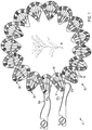
- FIG. 1 illustrates a system 10 for promoting growth of a plant 14, according to one or more embodiments.
- System 10 includes a body 85, a first wire 86, a current source 11, and/or other components.
- the depiction of plant 14 as a single entity is not meant to be limiting.
- Plant 14 may include one or more plants and/or other organisms.
- plant 14 may include an edible and/or commercial crop.
- plant 14 may comprise (one or more types of) algae.
- Body 85 of system 10 in FIG. 1 includes two intertwined helically wound runners - runner 88 and runner 89 - sharing the same (circular) axis, coupled by struts 90 and having one or more conductive wires spirally wound around one or both runners.
- runner 88 and runner 89 of body 85 form cores around which wire 86 and wire 87 are spirally wound, respectively.
- body 85 includes two wires: wire 86 and wire 87.
- system 10 includes one runner, three runners, and/or another number of runners.
- Runner 88 and runner 89 of body 85 and system 10 in FIG. 1 are arranged in the shape of a three-dimensional curve similar to or substantially the same as a helix, bend with its ends arranged together. It is noted that the shape of body 85 resembles the general shape of DNA.
- the shape of the cross-section of a runner may include one or more of a circle, an oval, a square, a triangle, a rectangle, an angular shape, a polygon, and/or other shapes.
- the width and height of the cross-section of a runner may be limited for practical purposes.
- body 85 it may be preferred arrange body 85 such that there is available space within the periphery of body 85, as shown, e.g., in FIG. 1 .
- the shape of the cross-section of runner 88 and runner 89 is a circle. Note that embodiments of this disclosure are not intended to be limited by any of the given examples.
- Runner 88, runner 89 and/or struts 90 of system 10 in FIG. 1 may be manufactured from one or more of plastic, plastic plated with metals including copper, nickel, iron, soft iron, nickel alloys, and/or other metals and alloys, and/or other materials.
- runner 88, runner 89 and struts 90 are manufactured from non-conductive material.
- Runner 88, runner 89, and struts 90 may be manufactured from different materials.
- Runner 88, runner 89, and struts 90 may be manufactured through integral construction or formed separately prior to being assembled. The preceding statement is not intended to limit the (process of) manufacture of bodies similar to or substantially the same as body 85 in any way.
- wire 86 and wire 87 may be insulated, uninsulated, or partially insulated and partially uninsulated.
- the shape of body 85 of system 10 in FIG. 1 may be generally toroidal.
- the body of system 10 may be arranged in any planar shape, including circular, polygonal, and/or other shapes.
- a body such as body 85 may be arranged in a three-dimensional curve (a.k.a. space curve).
- Runner 88 and runner 89 of body 85 may form cores around which wire 86 and wire 87 are spirally wound, respectively.
- wire 86 and wire 87 may be arranged in a helical shape having axes that coincide with runner 88 and runner 89, respectively. As shown in FIG.
- wire 86 and 87 may be wound such that they go around any of struts 90 of body 85 and/or around any points of engagement between one of struts 90 and one of runners 88 and 89.
- the number of wire turns per complete revolution of a runner and/or the number of wire turns between adjacent struts may be characteristic measurements/features of body 85.
- wire 86 and wire 87 are arranged to make approximately three to five turns between adjacent struts associated with runner 88 and runner 89, respectively, and/or some other number of turns.
- the depiction of FIG. 1 is intended to be exemplary, and in no way limiting.
- Wire 86 may include two leads - lead 86a and lead 86b.
- Wire 87 may include two leads - lead 87a and lead 87b.
- body 85 is electrically coupled with one or more power sources and/or current sources, such as, e.g., current source 11 and/or a current source 12, arranged such that electrical coupling with one or both of wire 86 and wire 87 may be established, e.g. through coupling of current source 11 with lead 86a and 86b of wire 86 and through coupling of current source 12 with lead 87a and 87b of wire 87.
- the current supplied to wire 86 may be a direct current or an alternating current.
- the current supplied to wire 87 may be a direct current or an alternating current.
- the currents supplied to wire 86 and wire 87 may flow in the same direction or the opposite direction.
- operating frequencies ranging from 0 Hz to 100 GHz are contemplated.
- Operating currents ranging from 1 pA to 10 A are contemplated.
- Operating voltages ranging from 1 mV to 20 kV are contemplated.
- a root mean square voltage of about 12 V is supplied to wire 86.
- the frequency of the alternating current supplied to wire 86 is between 0 Hz and 20 kHz.
- the current is less than about 1 pA, 1 nA, 1 mA, 100 mA, 250 mA, 500 mA, and/or other amounts of current.
- the operating frequencies for wire 86 and wire 87 may be the same or different.
- System 10 may be used to exploit the electromagnetic field that is created in and/or around body 85 when electrical power is supplied to one or more wires of body 85.
- the electromagnetic field promotes growth of a plant 14 disposed within or near the periphery of body 85.
- an electrical system including a body similar to or substantially the same as body 85 in FIG. 1 , thus including wire 86 and wire 87, may be configured to have a current in wire 86 flowing in the opposite direction as the current in wire 87.
- the current supplied to one wire may be a direct current, whereas the current supplied to another wire may be an alternating current.
- system 10 may include multiple bodies similar to or substantially the same as body 85. Currents for these multiple bodies may be supplied by one or more power sources and/or current sources.
- the shape of body 85 of system 10 is arranged around and/or near multiple plants and/or other organisms.
- system 10 may be configured and arranged to encompass a petri dish, a planter, a (photo)bioreactor, a growing tank, a row of planted crops, a green house, a field of plants, and/or any other conventionally used arrangement to grow plants.
- body 85 may be configured such that the dimensions of the available space within the periphery of body 85 has predetermined dimensions.
- the predetermined dimension includes a diameter of 1 inch, 1 foot, 3 feet, 6 feet, and/or another suitable dimension.
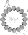
- FIG. 2 illustrates a system 20 for promoting growth of plant 14, according to one or more embodiments.
- System 20 includes a body 95, a wire 96, current source 11, and/or other components.
- Plant 14 may include one or more plants and/or other organisms.
- plant 14 may include an edible and/or commercial crop.
- plant 14 may comprise one or more types of algae and/or phytoplankton.
- plant 14 may comprise (edible) seaweed, Spirulina, Chlorella, and/or types of algae suitable for the production of biodiesel and/or biofuel.
- Body 95 of system 20 in FIG. 2 includes two intertwined helically wound runners - runner 97 and runner 98 - sharing the same circular axis. Both runners are coupled by struts. Wire 96 is spirally wound around both runners of body 95. In some embodiments, system 20 includes one runner, three runners, and/or another number of runners. Wire 96 may be insulated, uninsulated, or partially insulated and partially uninsulated. Wire 96 may include two leads - lead 96a and lead 96b. The resulting shape of body 95 with wire 96 may be referred to as a helicoidal shape. In system 20, body 95 is electrically coupled with one or more power sources and/or current sources, such as, e .
- current source 11 arranged such that electrical coupling with wire 96 may be established, e . g . through coupling of current source 11 with lead 96a and 96b of wire 96.
- the current supplied to wire 96 may be a direct current or an alternating current.
- the runners of system 20 may be similar to or substantially the same as the runners of system 10 in FIG. 1 .
- alternating currents in system 20 For alternating currents in system 20, operating frequencies ranging from 0 Hz to 100 GHz are contemplated. Operating currents ranging from 1 pA to 10 A are contemplated. Operating voltages ranging from 1 mV to 15 kV are contemplated. In some embodiments, the operating voltage is matched to the membrane potential of a particular plant cell. In some embodiments, a root mean square voltage of about 12 V is supplied to wire 96. In a preferred embodiment, the frequency of the alternating current supplied to wire 96 is between 0 Hz and 20 kHz. In some embodiments, the current is about 1 pA, 1 nA, 1 mA, 50 mA, 100 mA, 250 mA, 500 mA, and/or other amounts of current. System 20 may be used to exploit the electromagnetic field that is created in and/or around body 95 when electrical power is supplied to one or more wires of body 95. The electromagnetic field promotes growth of a plant 14 disposed within or near the periphery of
- system 20 may include multiple bodies similar to or substantially the same as body 95. Currents for these multiple bodies may be supplied by one or more power sources and/or current sources.
- a system may include a combination of one or more bodies similar to or substantially the same as body 85 and one or more bodies similar to or substantially the same as body 95.
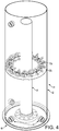
- FIG. 4 illustrates a system 40 for promoting growth of certain plants, according to one or more embodiments.
- system 40 may be used to promote growth of plants that can thrive while submerged in water and/or move with fluids in motion, such as, e . g ., algae.
- System 40 may include a tank 41, a hull 42, one or more ports 43, an inner pipe 44, helical coil 85a, support member 85b, and/or other components.
- Helical coil 85a may be held in place within tank 41 and/or physically supported by support member 85b.
- support member 85b may comprise a shelf.
- Pumps (not depicted) may be used to circulate fluids within tank 41 of system 40.
- one or more pumps may be operatively engaged with system 40 through one or more ports 43.
- the pumps may move fluid and plants up near the periphery of hull 42 and back down through inner pipe 44, and/or vice versa.
- hull 42 may be taller than inner pipe 44 to accommodate this circulation.
- the height of system 40 may range from about 3 feet to about 10 feet, and/or other suitable dimensions.
- System 40 may include one or more light sources (not depicted in FIG. 4 ) to, e . g ., promote growth of the plants within tank 41.
- one or more light sources may be embedded in one or more of the elements depicted in FIG. 4 .
- the bottom of tank 41 may comprise one or more light sources.
- system 40 may include a protective shell (not depicted in FIG. 4 ) so that fluids and/or plants do not directly come in contact with helical coil 85.
- System 40 may include wires (not depicted in FIG. 4 ) and one or more current sources (not depicted in FIG. 1 ) configured to create a particular electromagnetic field in and/or around helical coil 85a in a way that is similar to the described functionality of system 10 in FIG. 1 .
- the orientation of system 40 is not intended to be limited to the exemplary embodiment depicted in FIG. 4 .
- tank 41 may be placed vertically, horizontally, and/or diagonally.
- the angle of tank 41 may be adjusted to allow maximum exposure to a light source, such as, e . g ., the sun.
- multiple tanks similar to tank 41 may be arranged and/or controlled in a coordinated fashion.
- a significant electromagnetic field may be determined as an electromagnetic field of at least a predetermined threshold level of tesla.
- the predetermined threshold may be 1pT, 1nT, 1 mT, 10 mT, 100 mT, and/or another threshold.
- the growth rate, or range of typical growth rates, of the particular type of plant may be increased to a higher growth rate, or higher range of growth rates, for the particular plant.
- a unit of growth rate may be inch/day, or another unit expressing some length, area, volume, or size per unit of time, and/or another appropriate unit.
- growth rate may be expressed though lipid production rate, starch content production rate, biomass content production rate.
- a specific type of plant may have a typical maximum growth level, under growing conditions that lack a significant electromagnetic field.
- the maximum growth level, or range of typical maximum growth levels, of the specific type of plant may be increased to a higher maximum growth level, or higher range of maximum growth levels, for the specific plant.
- Maximum growth level may be expressed in inches, square inches, liters, kilograms, lipid content, and/or another unit expressing some length, area, volume, weight, or size, and/or another appropriate unit.
- a particular type of plant may have a typical maximum yield, under growing conditions that lack a significant electromagnetic field.
- the maximum yield, or range of typical maximum yields, of the particular type of plant may be increased to a higher maximum yield, or higher range of maximum yields, for the particular plant.
- Maximum yield may be expressed in volume or weight per area and/or period, such as kilogram/square feet, or pounds per acre per week, and/or other units as appropriate.
- an application for any of the described systems may exploit an improved and/or increased level of protein biosynthesis for organisms exposed to an electromagnetic field created by, e.g., system 10 or system 20.
- FIG. 3 illustrates a method 300 for promoting growth of a plant.
- the operations of method 300 presented below are intended to be illustrative. In certain embodiments, method 300 may be accomplished with one or more additional operations not described, and/or without one or more of the operations discussed. Additionally, the order in which the operations of method 300 are illustrated in FIG. 3 and described below is not intended to be limiting.
- method 300 may be implemented in one or more processing devices (e . g ., a digital processor, an analog processor, a digital circuit designed to process information, an analog circuit designed to process information, a state machine, and/or other mechanisms for electronically processing information).
- the one or more processing devices may include one or more devices executing some or all of the operations of method 300 in response to instructions stored electronically on an electronic storage medium.
- the one or more processing devices may include one or more devices configured through hardware, firmware, and/or software to be specifically designed for execution of one or more of the operations of method 300.
- a body is installed around or near a plant.
- the body includes two intertwined helically wound runners, a conductive wire, and a current source.
- the runners are arranged in at least two complete revolutions per runner, wherein the first runner is coupled to the second runner by struts.
- the wire is carried by the first runner.
- the current source is arranged to electrically coupled with two leads of the wire causing a current through the wire along the first runner.
- operation 302 is performed by a user of system 10 (shown in FIG. 1 and described above).
- operation 304 a current is supplied to the wire such that an electromagnetic field is created within and near the body that causes promotion of growth of the plant disposed within or near the body.
- operation 304 is performed by a current source similar to or substantially the same as current source 11 (shown in FIG. 1 and described above).
Landscapes
- Life Sciences & Earth Sciences (AREA)
- Biodiversity & Conservation Biology (AREA)
- Botany (AREA)
- Ecology (AREA)
- Forests & Forestry (AREA)
- Environmental Sciences (AREA)
- Cultivation Of Plants (AREA)
Claims (15)
- Elektrisches System zur Förderung des Wachstums einer Pflanze, wobei das System Folgendes umfasst:einen Körper, der zwei ineinander verschlungene schraubenförmig gewundene Läufer umfasst, die in mindestens zwei vollständigen Umdrehungen pro Läufer angeordnet sind, wobei ein erster Läufer mit einem zweiten Läufer durch Verstrebungen gekoppelt ist, wobei der Körper einen Umfang aufweist, wobei der Körper um eine Pflanze herum oder nahe einer Pflanze installiert ist;einen ersten Draht, der von dem ersten Läufer getragen wird, wobei der erste Draht leitfähig ist; undeine Stromquelle, die so angeordnet ist, dass sie mit zwei Leitungen des ersten Drahts elektrisch gekoppelt ist, wodurch ein erster Strom durch den ersten Draht entlang des ersten Läufers bewirkt wird, wobei die Stromquelle so konfiguriert ist, dass sie den ersten Strom durch den ersten Draht bewirkt, so dass ein elektromagnetisches Feld in dem Körper und um den Körper herum erzeugt wird, das das Wachstum der Pflanze fördert, die innerhalb oder nahe dem Umfang des Körpers angeordnet ist.
- System nach Anspruch 1, wobei der erste Draht ferner von dem zweiten Läufer getragen wird, wobei der erste Draht spiralförmig sowohl um den ersten Läufer als auch den zweiten Läufer gewickelt ist.
- System nach Anspruch 1, wobei der erste Draht spiralförmig um den ersten Läufer des Körpers gewickelt ist, so dass der erste Draht schraubenförmig angeordnet ist und eine Achse aufweist, die mit dem ersten Läufer übereinstimmt.
- System nach Anspruch 1, wobei die Stromquelle so konfiguriert ist, dass der erste Strom durch den ersten Draht ein Wechselstrom ist, wobei der Wechselstrom eine Frequenz zwischen 0 Hz und 20 kHz aufweist und wobei der Wechselstrom weniger als etwa 250 mA beträgt; oder wobei die Stromquelle so konfiguriert ist, dass der erste Strom durch den ersten Draht ein Wechselstrom ist, der eine Frequenz in einem Bereich der menschlich wahrnehmbaren akustischen Empfindlichkeit aufweist.
- System nach Anspruch 1, wobei die Stromquelle so konfiguriert ist, dass den beiden Leitungen des ersten Drahts eine Effektivspannung von etwa 12 V zugeführt wird.
- System nach Anspruch 1, das ferner einen zweiten Draht umfasst, der von dem zweiten Läufer getragen wird, wobei der zweite Draht leitfähig ist, wobei eine zweite Stromquelle so angeordnet ist, dass sie mit zwei Leitungen des zweiten Drahts elektrisch gekoppelt ist, wodurch ein zweiter Strom durch den zweiten Draht entlang des zweiten Läufers bewirkt wird, wobei die zweite Stromquelle so konfiguriert ist, dass sie den zweiten Strom durch den zweiten Draht bewirkt, so dass das elektromagnetische Feld modifiziert wird.
- System nach Anspruch 6, wobei der zweite Draht spiralförmig um den zweiten Läufer des Körpers gewickelt ist, so dass der zweite Draht schraubenförmig angeordnet ist und eine Achse aufweist, die mit dem zweiten Läufer übereinstimmt.
- System nach Anspruch 6, wobei die zweite Stromquelle der Stromquelle entspricht und optional wobei der erste Strom und der zweite Strom in einer gleichen Richtung fließen oder wobei der erste Strom und der zweite Strom in einer ungleichen Richtung fließen.
- System nach Anspruch 1, wobei die Pflanze Pflanzen umfasst, die gedeihen, während sie untergetaucht sind, wobei das System ferner einen Behälter umfasst, der so konfiguriert ist, dass er Fluid enthält, in das Pflanzen untergetaucht sind, wobei der Körper innerhalb des Behälters oder nahe dem Behälter angeordnet ist, so dass das erzeugte elektromagnetische Feld das Wachstum der Pflanzen in dem Fluid, das in dem Behälter enthalten ist, fördert.
- Verfahren zur Förderung des Wachstums einer Pflanze, wobei das Verfahren Folgendes umfasst:Installieren eines Körpers um eine Pflanze herum oder nahe einer Pflanze, wobei der Körper Folgendes umfasst:zwei ineinander verschlungene schraubenförmig gewundene Läufer, die in mindestens zwei vollständigen Umdrehungen pro Läufer angeordnet sind, wobei ein erster Läufer mit einem zweiten Läufer durch Verstrebungen gekoppelt ist;einen ersten Draht, der von dem ersten Läufer getragen wird, wobei der erste Draht leitfähig ist; undeine Stromquelle, die so angeordnet ist, dass sie mit zwei Leitungen des ersten Drahts elektrisch gekoppelt ist, wodurch ein erster Strom durch den ersten Draht entlang des ersten Läufers bewirkt wird;Anlegen des ersten Stroms an den ersten Draht, so dass ein elektromagnetisches Feld in und nahe dem Körper erzeugt wird, das eine Förderung des Wachstums der Pflanze bewirkt, die in oder in der Nähe des Körpers angeordnet ist.
- Verfahren nach Anspruch 10, wobei der erste Draht des Körpers ferner von dem zweiten Läufer des Körpers getragen wird, wobei der erste Draht spiralförmig sowohl um den ersten Läufer als auch den zweiten Läufer gewickelt ist.
- Verfahren nach Anspruch 10, wobei die Stromquelle so konfiguriert ist, dass der erste Strom durch den ersten Draht ein Wechselstrom ist, wobei der Wechselstrom eine Frequenz zwischen 0 Hz und 20 kHz aufweist.
- Verfahren nach Anspruch 10, wobei der Körper ferner einen zweiten Draht umfasst, der von dem zweiten Läufer getragen wird, wobei der zweite Draht leitfähig ist, wobei die Stromquelle ferner so angeordnet ist, dass sie mit zwei Leitungen des zweiten Drahts elektrisch gekoppelt ist, wodurch ein zweiter Strom durch den zweiten Draht entlang des zweiten Läufers bewirkt wird, so dass das elektromagnetische Feld modifiziert wird.
- Verfahren nach Anspruch 13, das ferner Folgendes umfasst: Anlegen des zweiten Stroms an den zweiten Draht, so dass das elektromagnetische Feld modifiziert wird.
wobei der erste Strom und der zweite Strom Wechselströme sind, die in einer gleichen Richtung fließen; oder
wobei der erste Strom und der zweite Strom Wechselströme sind, die in einer ungleichen Richtung fließen. - Verfahren nach Anspruch 10, wobei die Pflanze eine typische Wachstumsrate unter Wachstumsbedingungen aufweist, die kein bedeutendes elektromagnetisches Feld aufweisen, und wobei die Förderung des Wachstums eine schnellere Wachstumsrate als die typische Wachstumsrate umfasst; und/oder wobei die Pflanze ein typisches maximales Wachstumsniveau unter Wachstumsbedingungen aufweist, die kein bedeutendes elektromagnetisches Feld aufweisen, und wobei die Förderung des Wachstums ein maximales Wachstumsniveau umfasst, das höher als das typische maximale Wachstumsniveau ist; und/oder wobei die Pflanze einen typischen maximalen Ertrag unter Wachstumsbedingungen aufweist, die kein bedeutendes elektromagnetisches Feld aufweisen, und wobei die Förderung des Wachstums einen maximalen Ertrag umfasst, der höher als der typische maximale Ertrag ist.
Priority Applications (1)
| Application Number | Priority Date | Filing Date | Title |
|---|---|---|---|
| PL13741523T PL2806725T3 (pl) | 2012-01-27 | 2013-01-25 | Zastosowania w rolnictwie przewodnika z podwójną spiralą |
Applications Claiming Priority (2)
| Application Number | Priority Date | Filing Date | Title |
|---|---|---|---|
| US13/360,522 US8919035B2 (en) | 2012-01-27 | 2012-01-27 | Agricultural applications of a double helix conductor |
| PCT/US2013/023111 WO2013112810A1 (en) | 2012-01-27 | 2013-01-25 | Agricultural applications of a double helix conductor |
Publications (3)
| Publication Number | Publication Date |
|---|---|
| EP2806725A1 EP2806725A1 (de) | 2014-12-03 |
| EP2806725A4 EP2806725A4 (de) | 2015-09-23 |
| EP2806725B1 true EP2806725B1 (de) | 2017-01-18 |
Family
ID=48869009
Family Applications (1)
| Application Number | Title | Priority Date | Filing Date |
|---|---|---|---|
| EP13741523.8A Active EP2806725B1 (de) | 2012-01-27 | 2013-01-25 | Landwirtschaftliche anwendungen eines doppelhelixleiters |
Country Status (6)
| Country | Link |
|---|---|
| US (2) | US8919035B2 (de) |
| EP (1) | EP2806725B1 (de) |
| JP (2) | JP6144283B2 (de) |
| ES (1) | ES2622167T3 (de) |
| PL (1) | PL2806725T3 (de) |
| WO (1) | WO2013112810A1 (de) |
Families Citing this family (23)
| Publication number | Priority date | Publication date | Assignee | Title |
|---|---|---|---|---|
| US8653925B2 (en) | 2011-03-03 | 2014-02-18 | Lifewave, Inc. | Double helix conductor |
| USD738358S1 (en) * | 2011-08-19 | 2015-09-08 | Lifewave, Inc. | Double helix antenna |
| US8919035B2 (en) | 2012-01-27 | 2014-12-30 | Medical Energetics Ltd | Agricultural applications of a double helix conductor |
| US8652023B2 (en) | 2012-02-13 | 2014-02-18 | Lifewave, Inc. | Health applications of a double helix conductor |
| US8749333B2 (en) | 2012-04-26 | 2014-06-10 | Lifewave, Inc. | System configuration using a double helix conductor |
| US9504844B2 (en) | 2013-06-12 | 2016-11-29 | Medical Energetics Ltd | Health applications for using bio-feedback to control an electromagnetic field |
| US9724531B2 (en) | 2013-10-28 | 2017-08-08 | Medical Energetics Ltd. | Double helix conductor with light emitting fluids for producing photobiomodulation effects in living organisms |
| US9636518B2 (en) | 2013-10-28 | 2017-05-02 | Medical Energetics Ltd. | Nested double helix conductors |
| CA2936930A1 (en) * | 2013-12-13 | 2015-06-18 | Timothy James ROSSI | Method and system of using electromagnetism to control fertilizer leaching |
| US9707568B2 (en) | 2014-12-12 | 2017-07-18 | Timothy James Rossi | Method and system for using electromagnetism to control fertilizer leaching |
| US9861830B1 (en) | 2013-12-13 | 2018-01-09 | Medical Energetics Ltd. | Double helix conductor with winding around core |
| EP3114695B1 (de) | 2014-03-05 | 2019-08-07 | Medical Energetics Ltd. | Doppelhelixleiter mit acht verbindern und gegendrehenden feldern |
| US9463331B2 (en) | 2014-04-07 | 2016-10-11 | Medical Energetics Ltd | Using a double helix conductor to treat neuropathic disorders |
| US9370667B2 (en) | 2014-04-07 | 2016-06-21 | Medical Energetics Ltd | Double helix conductor for medical applications using stem cell technology |
| AU2015201169A1 (en) | 2014-04-10 | 2015-10-29 | Medical Energetics Ltd. | Double helix conductor with counter-rotating fields |
| US10102955B2 (en) | 2015-02-20 | 2018-10-16 | Medical Energetics Ltd. | Dual double helix conductors |
| US9827436B2 (en) * | 2015-03-02 | 2017-11-28 | Medical Energetics Ltd. | Systems and methods to improve the growth rate of livestock, fish, and other animals |
| CA3020622C (en) | 2015-06-09 | 2021-02-16 | Medical Energetics Limited | Dual double helix conductors used in agriculture |
| WO2017037143A1 (en) | 2015-09-01 | 2017-03-09 | Medical Energetics Ltd. | Rotating dual double helix conductors |
| US11612109B1 (en) * | 2022-02-24 | 2023-03-28 | Welivitigoda Rajitha Danesha Wimaladharma | Magnetic device and method for growing plants |
| US12433203B2 (en) * | 2022-08-22 | 2025-10-07 | Rutgers, The State University Of New Jersey | Plant-safe electrospray water and nutrient delivery system |
| IT202200021009A1 (it) * | 2022-10-12 | 2024-04-12 | Themis S R L S | Sistema per l’accrescimento, lo sviluppo e la cura di specie vegetali con influssi magnetici in ambito marino, terrestre ed extraterrestre |
| IT202300006264A1 (it) * | 2023-03-31 | 2024-10-01 | Alessandro Capponi | Macchina e relativo procedimento per la variazione genetica delle piante |
Family Cites Families (83)
| Publication number | Priority date | Publication date | Assignee | Title |
|---|---|---|---|---|
| FR719837A (fr) | 1930-10-13 | 1932-02-10 | Telefunken Gmbh | Perfectionnements aux antennes directives pour ondes courtes |
| US2035274A (en) * | 1932-01-12 | 1936-03-24 | Bell Telephone Labor Inc | Coaxial conductor system |
| GB479841A (en) | 1935-08-12 | 1938-02-07 | Siemens Ag | Improvements in or relating to air-space-insulated high frequency electric cables |
| BE440246A (de) | 1940-01-20 | |||
| US2850666A (en) | 1955-12-01 | 1958-09-02 | Hughes Aircraft Co | Helix structure for traveling-wave tubes |
| US3037175A (en) | 1958-05-12 | 1962-05-29 | Bell Telephone Labor Inc | Broadband transformers |
| GB930382A (de) | 1959-04-16 | |||
| US3519964A (en) | 1968-07-26 | 1970-07-07 | Microwave Ass | High power slow wave circuit |
| US3588689A (en) | 1969-06-16 | 1971-06-28 | Harry F Crawford | Variable impedance system for electrical cable fault locating and temperature monitoring |
| US3683393A (en) | 1970-07-06 | 1972-08-08 | Electrotec Corp | Helical dipole antenna |
| US3760812A (en) * | 1971-03-19 | 1973-09-25 | Univ Minnesota | Implantable spiral wound stimulation electrodes |
| US3774452A (en) | 1971-11-22 | 1973-11-27 | Meter Service & Supply Co | Helical coil bourdon tube support assembly |
| US4266532A (en) | 1976-11-17 | 1981-05-12 | Electro-Biology, Inc. | Modification of the growth, repair and maintenance behavior of living tissues and cells by a specific and selective change in electrical environment |
| US4131759A (en) | 1977-08-10 | 1978-12-26 | United States Steel Corporation | Slip sleeve mechanism for a strength tapered caged armored electromechanical cable |
| US4229676A (en) | 1979-03-16 | 1980-10-21 | Hughes Aircraft Company | Helical slow-wave structure assemblies and fabrication methods |
| FR2477019A1 (fr) * | 1980-03-03 | 1981-09-04 | Flux Yang Ste Civile | Anneau torique a spires pouvant creer un champ magnetique agissant sur les circulations bio-electriques d'un organisme vivant |
| WO1982001286A1 (en) | 1980-09-29 | 1982-04-15 | Belikov V | Electric motor with screw-shaped stator |
| US4489276A (en) | 1982-01-20 | 1984-12-18 | The United States Of America As Represented By The United States Department Of Energy | Dual-cone double-helical downhole logging device |
| US4832051A (en) * | 1985-04-29 | 1989-05-23 | Symbion, Inc. | Multiple-electrode intracochlear device |
| ES2019438B3 (es) | 1987-09-03 | 1991-06-16 | Peter Schuster | Transmision lineal libre de contacto |
| US4989617A (en) | 1989-07-14 | 1991-02-05 | Case Western Reserve University | Intramuscular electrode for neuromuscular stimulation system |
| US5077934A (en) | 1989-09-22 | 1992-01-07 | Life Resonances, Inc. | Method and apparatus for controlling plant growth |
| US5851206A (en) | 1990-03-13 | 1998-12-22 | The Regents Of The University Of California | Method and apparatus for endovascular thermal thrombosis and thermal cancer treatment |
| US5173669A (en) * | 1990-09-04 | 1992-12-22 | Hughes Aircraft Company | Slow-wave structure having block supported helix structure |
| NL9002005A (nl) | 1990-09-12 | 1992-04-01 | Philips Nv | Transformator. |
| US5366493A (en) | 1991-02-04 | 1994-11-22 | Case Western Reserve University | Double helix functional stimulation electrode |
| US5359340A (en) | 1992-09-30 | 1994-10-25 | Fujitsu Limited | Helical antenna for portable radio communication equipment |
| US5654723A (en) | 1992-12-15 | 1997-08-05 | West Virginia University | Contrawound antenna |
| US5339061A (en) | 1993-06-01 | 1994-08-16 | Michael Ebert | Iron-free transformer |
| US5464456A (en) * | 1993-06-30 | 1995-11-07 | Kertz; M. Glen | Electronic stimulation of plants |
| CA2131950A1 (en) | 1993-09-16 | 1995-03-17 | Kazumi Masaki | Fm theta-inducing audible sound, and method, device and recorded medium to generate the same |
| EP0666612B1 (de) | 1994-02-04 | 2001-10-24 | Orbital Sciences Corporation | Sich selbst entfaltende Wendelstruktur |
| US5819467A (en) * | 1994-12-05 | 1998-10-13 | Zucker; Jonathan M. | Method of stimulating plant growth |
| US6239760B1 (en) | 1995-08-14 | 2001-05-29 | Vortekx, Inc. | Contrawound toroidal helical antenna |
| US6042605A (en) | 1995-12-14 | 2000-03-28 | Gore Enterprose Holdings, Inc. | Kink resistant stent-graft |
| US6552530B1 (en) * | 1997-10-14 | 2003-04-22 | Hex Technology Holding Limited | Super-toroidal electric and magnetic field generator/detector, and sample analyser and treatment apparatus using same |
| US5892480A (en) | 1997-04-09 | 1999-04-06 | Harris Corporation | Variable pitch angle, axial mode helical antenna |
| US5909165A (en) | 1997-08-29 | 1999-06-01 | The United States Of America As Represented By The Secretary Of The Army | Chiron twister |
| US6005462A (en) | 1998-02-24 | 1999-12-21 | Myers; John Leonard | Electromagnetic core-energy actuator |
| US6169523B1 (en) | 1999-01-13 | 2001-01-02 | George Ploussios | Electronically tuned helix radiator choke |
| AU6352101A (en) | 2000-04-15 | 2001-10-30 | Morrison, Ian | Apparatus for electromagnetic spectroscopy |
| US6300920B1 (en) | 2000-08-10 | 2001-10-09 | West Virginia University | Electromagnetic antenna |
| US6856078B2 (en) | 2001-06-27 | 2005-02-15 | Asm America, Inc. | Lamp filament design |
| US6921042B1 (en) | 2001-09-24 | 2005-07-26 | Carl L. Goodzeit | Concentric tilted double-helix dipoles and higher-order multipole magnets |
| US20030158585A1 (en) | 2002-02-19 | 2003-08-21 | Burnett Daniel R. | Method and apparatus for electromagnetic stimulation of nerve, muscle, and body tissues |
| US6978179B1 (en) | 2002-02-27 | 2005-12-20 | Flagg Rodger H | Method and apparatus for magnetic brain wave stimulation |
| US20030230427A1 (en) | 2002-05-02 | 2003-12-18 | Gareis Galen Mark | Surfaced cable filler |
| US7154368B2 (en) | 2003-10-15 | 2006-12-26 | Actown Electricoil, Inc. | Magnetic core winding method, apparatus, and product produced therefrom |
| US20050121396A1 (en) | 2003-12-09 | 2005-06-09 | Kosakewich Darrell S. | Apparatus and method for treating substances with electromagnetic wave energy |
| US7520848B2 (en) | 2004-04-09 | 2009-04-21 | The Board Of Trustees Of The Leland Stanford Junior University | Robotic apparatus for targeting and producing deep, focused transcranial magnetic stimulation |
| US7148783B2 (en) | 2004-11-05 | 2006-12-12 | Harris Corporation | Microwave tunable inductor and associated methods |
| US20080161884A1 (en) | 2004-12-23 | 2008-07-03 | Mark Chandler | Method and apparatus for treating or preventing a medical condition |
| US20070258329A1 (en) | 2005-01-27 | 2007-11-08 | Timothy Winey | Method and apparatus for the exploitation of piezoelectric and other effects in carbon-based life forms |
| US20070024520A1 (en) | 2005-07-14 | 2007-02-01 | Duane Preble | Spiral antenna |
| WO2008005843A2 (en) | 2006-06-30 | 2008-01-10 | Cyberkinetics Neurotechnology Systems, Inc. | Nerve regeneration system and lead devices associated therewith |
| US7375449B2 (en) | 2006-08-17 | 2008-05-20 | Butterfield Paul D | Optimized modular electrical machine using permanent magnets |
| US7998139B2 (en) | 2007-04-25 | 2011-08-16 | Vivant Medical, Inc. | Cooled helical antenna for microwave ablation |
| WO2008133575A1 (en) | 2007-04-25 | 2008-11-06 | St. Jude Medical Ab | A medical implantable lead and a method for attaching the same |
| US7880578B2 (en) | 2007-10-02 | 2011-02-01 | Advanced Magnet Lab, Inc. | Conductor assembly including a flared aperture region |
| EP2250652A1 (de) | 2008-02-18 | 2010-11-17 | Advanced Magnet Lab, Inc. | Entwurf einer spiralspule und verfahren zur direkten herstellung aus einer leitenden schicht |
| US7674973B2 (en) | 2008-04-18 | 2010-03-09 | George Cardas | Electrical conductor and cable utilizing same |
| US20100005711A1 (en) | 2008-07-09 | 2010-01-14 | Sartec Corporation | Lighted Algae Cultivation Systems |
| EP2349475B1 (de) | 2008-08-25 | 2016-01-06 | Applied Magnetics, LLC | Systeme zur bereitstellung einer magnetresonanzbehandlung an einem patienten |
| US20100113862A1 (en) | 2008-11-05 | 2010-05-06 | Kotowich Alan W J | Treatment of amelioration of arthritic joint pain |
| US8332042B2 (en) | 2009-01-15 | 2012-12-11 | Medtronic, Inc. | Medical lead with stiffening coil |
| DE112010001330T5 (de) | 2009-03-26 | 2012-02-16 | Kenergy Inc. | MRT-kompatible implantierbare Anschlusselektroden-Schnittstelle |
| WO2010146220A1 (en) | 2009-06-17 | 2010-12-23 | Nexstim Oy | Magnetic stimulation device and method |
| GB2480610A (en) | 2010-05-24 | 2011-11-30 | Iain Norman Reid Findlay | Flexible tubing arranged on a support structure for growing plants |
| US20120143285A1 (en) | 2010-10-07 | 2012-06-07 | Jian Wang | Handheld excitation terminal and emf emitter providing dynamic optimization of emission and therapeutic effect and remote therapeutic system |
| US8653925B2 (en) | 2011-03-03 | 2014-02-18 | Lifewave, Inc. | Double helix conductor |
| US8919035B2 (en) | 2012-01-27 | 2014-12-30 | Medical Energetics Ltd | Agricultural applications of a double helix conductor |
| US8652023B2 (en) | 2012-02-13 | 2014-02-18 | Lifewave, Inc. | Health applications of a double helix conductor |
| US8749333B2 (en) | 2012-04-26 | 2014-06-10 | Lifewave, Inc. | System configuration using a double helix conductor |
| US9504844B2 (en) | 2013-06-12 | 2016-11-29 | Medical Energetics Ltd | Health applications for using bio-feedback to control an electromagnetic field |
| US9724531B2 (en) | 2013-10-28 | 2017-08-08 | Medical Energetics Ltd. | Double helix conductor with light emitting fluids for producing photobiomodulation effects in living organisms |
| US20150119630A1 (en) | 2013-10-28 | 2015-04-30 | Medical Energetics Ltd. | Double helix conductor with fiberoptic cable for producing effects in living organisms |
| US9636518B2 (en) | 2013-10-28 | 2017-05-02 | Medical Energetics Ltd. | Nested double helix conductors |
| EP3114695B1 (de) | 2014-03-05 | 2019-08-07 | Medical Energetics Ltd. | Doppelhelixleiter mit acht verbindern und gegendrehenden feldern |
| US9463331B2 (en) | 2014-04-07 | 2016-10-11 | Medical Energetics Ltd | Using a double helix conductor to treat neuropathic disorders |
| US9370667B2 (en) | 2014-04-07 | 2016-06-21 | Medical Energetics Ltd | Double helix conductor for medical applications using stem cell technology |
| AU2015201169A1 (en) | 2014-04-10 | 2015-10-29 | Medical Energetics Ltd. | Double helix conductor with counter-rotating fields |
| US10102955B2 (en) | 2015-02-20 | 2018-10-16 | Medical Energetics Ltd. | Dual double helix conductors |
| CA3020622C (en) | 2015-06-09 | 2021-02-16 | Medical Energetics Limited | Dual double helix conductors used in agriculture |
-
2012
- 2012-01-27 US US13/360,522 patent/US8919035B2/en active Active
-
2013
- 2013-01-25 JP JP2014554850A patent/JP6144283B2/ja not_active Expired - Fee Related
- 2013-01-25 EP EP13741523.8A patent/EP2806725B1/de active Active
- 2013-01-25 ES ES13741523.8T patent/ES2622167T3/es active Active
- 2013-01-25 WO PCT/US2013/023111 patent/WO2013112810A1/en not_active Ceased
- 2013-01-25 PL PL13741523T patent/PL2806725T3/pl unknown
-
2014
- 2014-12-29 US US14/584,634 patent/US10130044B1/en active Active
-
2016
- 2016-11-28 JP JP2016230012A patent/JP2017060514A/ja active Pending
Non-Patent Citations (1)
| Title |
|---|
| None * |
Also Published As
| Publication number | Publication date |
|---|---|
| US10130044B1 (en) | 2018-11-20 |
| WO2013112810A1 (en) | 2013-08-01 |
| EP2806725A4 (de) | 2015-09-23 |
| PL2806725T3 (pl) | 2017-07-31 |
| JP2017060514A (ja) | 2017-03-30 |
| EP2806725A1 (de) | 2014-12-03 |
| US8919035B2 (en) | 2014-12-30 |
| JP6144283B2 (ja) | 2017-06-07 |
| JP2015508637A (ja) | 2015-03-23 |
| US20130192129A1 (en) | 2013-08-01 |
| ES2622167T3 (es) | 2017-07-05 |
Similar Documents
| Publication | Publication Date | Title |
|---|---|---|
| EP2806725B1 (de) | Landwirtschaftliche anwendungen eines doppelhelixleiters | |
| US10224136B2 (en) | Dual double helix conductors used in agriculture | |
| US9636518B2 (en) | Nested double helix conductors | |
| US9724531B2 (en) | Double helix conductor with light emitting fluids for producing photobiomodulation effects in living organisms | |
| CN102687662B (zh) | 一种水上植物栽培筏及其制造方法 | |
| CN103371122B (zh) | 用于在鱼缸中控制藻华以及杀灭病原体的装置 | |
| US10155925B2 (en) | Rotating dual double helix conductors | |
| Chen et al. | The apple lipoxygenase MdLOX3 regulates salt tolerance and ABA sensitivity | |
| US20240316572A1 (en) | Bioelectric method for enhancement of cation uptake in vascular plants | |
| Mir et al. | Effects of Light Intensity and Spectrum Mix on Biomass, Growth and Resource Use Efficiency in Microgreen Species | |
| CN114664511A (zh) | 一种微型动物磁共振成像超导磁体与梯度装置 | |
| WO2022266728A1 (pt) | Sistema e método para eletroenergização de água e soluções aquosas para agropecuária, fluido eletroenergizado e uso correspondentes | |
| CN203985032U (zh) | 一种农业作物生长微粒子灌溉磁化器 | |
| CN104126534A (zh) | 一种用于室外土池培育单体牡蛎苗用的浮动网箱 | |
| JP6009835B2 (ja) | 太陽光発電装置 | |
| JP2015195793A (ja) | ユーグレナの増殖方法及び装置 | |
| CN207845651U (zh) | 一种制备虾青素的恒温槽 | |
| CN101993816A (zh) | 水葫芦马尾藻杂合种养植围栏——甲烷发生池 | |
| CN202179039U (zh) | 一种水产养殖笼 | |
| US9827436B2 (en) | Systems and methods to improve the growth rate of livestock, fish, and other animals | |
| CN207166064U (zh) | 一种电脑数据连接线 | |
| CN103430898A (zh) | 一种生态型集约化淡水养殖系统 | |
| Marroquin et al. | Make it Grow: The Effect of Fertilizer on Algae Growth | |
| Kim et al. | Perspective of entomopathogenic fungi as biological control agents | |
| Wang HuaSen et al. | Antisense-mediated depletion of tomato endoplasmic reticulum omega-3 fatty acid desaturase enhances thermal tolerance. |
Legal Events
| Date | Code | Title | Description |
|---|---|---|---|
| PUAI | Public reference made under article 153(3) epc to a published international application that has entered the european phase |
Free format text: ORIGINAL CODE: 0009012 |
|
| 17P | Request for examination filed |
Effective date: 20140826 |
|
| AK | Designated contracting states |
Kind code of ref document: A1 Designated state(s): AL AT BE BG CH CY CZ DE DK EE ES FI FR GB GR HR HU IE IS IT LI LT LU LV MC MK MT NL NO PL PT RO RS SE SI SK SM TR |
|
| DAX | Request for extension of the european patent (deleted) | ||
| REG | Reference to a national code |
Ref country code: DE Ref legal event code: R079 Ref document number: 602013016735 Country of ref document: DE Free format text: PREVIOUS MAIN CLASS: A01C0001000000 Ipc: A01G0007040000 |
|
| RAP1 | Party data changed (applicant data changed or rights of an application transferred) |
Owner name: MEDICAL ENERGETICS LTD. |
|
| RA4 | Supplementary search report drawn up and despatched (corrected) |
Effective date: 20150821 |
|
| RIC1 | Information provided on ipc code assigned before grant |
Ipc: A01G 7/04 20060101AFI20150817BHEP |
|
| GRAP | Despatch of communication of intention to grant a patent |
Free format text: ORIGINAL CODE: EPIDOSNIGR1 |
|
| INTG | Intention to grant announced |
Effective date: 20160812 |
|
| GRAS | Grant fee paid |
Free format text: ORIGINAL CODE: EPIDOSNIGR3 |
|
| GRAA | (expected) grant |
Free format text: ORIGINAL CODE: 0009210 |
|
| AK | Designated contracting states |
Kind code of ref document: B1 Designated state(s): AL AT BE BG CH CY CZ DE DK EE ES FI FR GB GR HR HU IE IS IT LI LT LU LV MC MK MT NL NO PL PT RO RS SE SI SK SM TR |
|
| REG | Reference to a national code |
Ref country code: GB Ref legal event code: FG4D |
|
| REG | Reference to a national code |
Ref country code: CH Ref legal event code: EP |
|
| REG | Reference to a national code |
Ref country code: AT Ref legal event code: REF Ref document number: 862341 Country of ref document: AT Kind code of ref document: T Effective date: 20170215 |
|
| REG | Reference to a national code |
Ref country code: IE Ref legal event code: FG4D |
|
| REG | Reference to a national code |
Ref country code: DE Ref legal event code: R096 Ref document number: 602013016735 Country of ref document: DE |
|
| REG | Reference to a national code |
Ref country code: FR Ref legal event code: PLFP Year of fee payment: 5 |
|
| REG | Reference to a national code |
Ref country code: NL Ref legal event code: FP |
|
| REG | Reference to a national code |
Ref country code: LT Ref legal event code: MG4D |
|
| PG25 | Lapsed in a contracting state [announced via postgrant information from national office to epo] |
Ref country code: BE Free format text: LAPSE BECAUSE OF NON-PAYMENT OF DUE FEES Effective date: 20170131 |
|
| REG | Reference to a national code |
Ref country code: AT Ref legal event code: MK05 Ref document number: 862341 Country of ref document: AT Kind code of ref document: T Effective date: 20170118 |
|
| REG | Reference to a national code |
Ref country code: ES Ref legal event code: FG2A Ref document number: 2622167 Country of ref document: ES Kind code of ref document: T3 Effective date: 20170705 |
|
| PG25 | Lapsed in a contracting state [announced via postgrant information from national office to epo] |
Ref country code: IS Free format text: LAPSE BECAUSE OF FAILURE TO SUBMIT A TRANSLATION OF THE DESCRIPTION OR TO PAY THE FEE WITHIN THE PRESCRIBED TIME-LIMIT Effective date: 20170518 Ref country code: LT Free format text: LAPSE BECAUSE OF FAILURE TO SUBMIT A TRANSLATION OF THE DESCRIPTION OR TO PAY THE FEE WITHIN THE PRESCRIBED TIME-LIMIT Effective date: 20170118 Ref country code: FI Free format text: LAPSE BECAUSE OF FAILURE TO SUBMIT A TRANSLATION OF THE DESCRIPTION OR TO PAY THE FEE WITHIN THE PRESCRIBED TIME-LIMIT Effective date: 20170118 Ref country code: GR Free format text: LAPSE BECAUSE OF FAILURE TO SUBMIT A TRANSLATION OF THE DESCRIPTION OR TO PAY THE FEE WITHIN THE PRESCRIBED TIME-LIMIT Effective date: 20170419 Ref country code: HR Free format text: LAPSE BECAUSE OF FAILURE TO SUBMIT A TRANSLATION OF THE DESCRIPTION OR TO PAY THE FEE WITHIN THE PRESCRIBED TIME-LIMIT Effective date: 20170118 Ref country code: NO Free format text: LAPSE BECAUSE OF FAILURE TO SUBMIT A TRANSLATION OF THE DESCRIPTION OR TO PAY THE FEE WITHIN THE PRESCRIBED TIME-LIMIT Effective date: 20170418 |
|
| PG25 | Lapsed in a contracting state [announced via postgrant information from national office to epo] |
Ref country code: RS Free format text: LAPSE BECAUSE OF FAILURE TO SUBMIT A TRANSLATION OF THE DESCRIPTION OR TO PAY THE FEE WITHIN THE PRESCRIBED TIME-LIMIT Effective date: 20170118 Ref country code: AT Free format text: LAPSE BECAUSE OF FAILURE TO SUBMIT A TRANSLATION OF THE DESCRIPTION OR TO PAY THE FEE WITHIN THE PRESCRIBED TIME-LIMIT Effective date: 20170118 Ref country code: SE Free format text: LAPSE BECAUSE OF FAILURE TO SUBMIT A TRANSLATION OF THE DESCRIPTION OR TO PAY THE FEE WITHIN THE PRESCRIBED TIME-LIMIT Effective date: 20170118 Ref country code: BG Free format text: LAPSE BECAUSE OF FAILURE TO SUBMIT A TRANSLATION OF THE DESCRIPTION OR TO PAY THE FEE WITHIN THE PRESCRIBED TIME-LIMIT Effective date: 20170418 Ref country code: PT Free format text: LAPSE BECAUSE OF FAILURE TO SUBMIT A TRANSLATION OF THE DESCRIPTION OR TO PAY THE FEE WITHIN THE PRESCRIBED TIME-LIMIT Effective date: 20170518 Ref country code: LV Free format text: LAPSE BECAUSE OF FAILURE TO SUBMIT A TRANSLATION OF THE DESCRIPTION OR TO PAY THE FEE WITHIN THE PRESCRIBED TIME-LIMIT Effective date: 20170118 |
|
| REG | Reference to a national code |
Ref country code: CH Ref legal event code: PL |
|
| REG | Reference to a national code |
Ref country code: DE Ref legal event code: R097 Ref document number: 602013016735 Country of ref document: DE |
|
| PG25 | Lapsed in a contracting state [announced via postgrant information from national office to epo] |
Ref country code: RO Free format text: LAPSE BECAUSE OF FAILURE TO SUBMIT A TRANSLATION OF THE DESCRIPTION OR TO PAY THE FEE WITHIN THE PRESCRIBED TIME-LIMIT Effective date: 20170118 Ref country code: SK Free format text: LAPSE BECAUSE OF FAILURE TO SUBMIT A TRANSLATION OF THE DESCRIPTION OR TO PAY THE FEE WITHIN THE PRESCRIBED TIME-LIMIT Effective date: 20170118 Ref country code: LI Free format text: LAPSE BECAUSE OF NON-PAYMENT OF DUE FEES Effective date: 20170131 Ref country code: EE Free format text: LAPSE BECAUSE OF FAILURE TO SUBMIT A TRANSLATION OF THE DESCRIPTION OR TO PAY THE FEE WITHIN THE PRESCRIBED TIME-LIMIT Effective date: 20170118 Ref country code: CH Free format text: LAPSE BECAUSE OF NON-PAYMENT OF DUE FEES Effective date: 20170131 Ref country code: CZ Free format text: LAPSE BECAUSE OF FAILURE TO SUBMIT A TRANSLATION OF THE DESCRIPTION OR TO PAY THE FEE WITHIN THE PRESCRIBED TIME-LIMIT Effective date: 20170118 |
|
| PLBE | No opposition filed within time limit |
Free format text: ORIGINAL CODE: 0009261 |
|
| STAA | Information on the status of an ep patent application or granted ep patent |
Free format text: STATUS: NO OPPOSITION FILED WITHIN TIME LIMIT |
|
| PG25 | Lapsed in a contracting state [announced via postgrant information from national office to epo] |
Ref country code: SM Free format text: LAPSE BECAUSE OF FAILURE TO SUBMIT A TRANSLATION OF THE DESCRIPTION OR TO PAY THE FEE WITHIN THE PRESCRIBED TIME-LIMIT Effective date: 20170118 Ref country code: MC Free format text: LAPSE BECAUSE OF FAILURE TO SUBMIT A TRANSLATION OF THE DESCRIPTION OR TO PAY THE FEE WITHIN THE PRESCRIBED TIME-LIMIT Effective date: 20170118 Ref country code: DK Free format text: LAPSE BECAUSE OF FAILURE TO SUBMIT A TRANSLATION OF THE DESCRIPTION OR TO PAY THE FEE WITHIN THE PRESCRIBED TIME-LIMIT Effective date: 20170118 Ref country code: LU Free format text: LAPSE BECAUSE OF NON-PAYMENT OF DUE FEES Effective date: 20170125 |
|
| 26N | No opposition filed |
Effective date: 20171019 |
|
| REG | Reference to a national code |
Ref country code: FR Ref legal event code: PLFP Year of fee payment: 6 |
|
| REG | Reference to a national code |
Ref country code: BE Ref legal event code: MM Effective date: 20170131 |
|
| PG25 | Lapsed in a contracting state [announced via postgrant information from national office to epo] |
Ref country code: SI Free format text: LAPSE BECAUSE OF FAILURE TO SUBMIT A TRANSLATION OF THE DESCRIPTION OR TO PAY THE FEE WITHIN THE PRESCRIBED TIME-LIMIT Effective date: 20170118 |
|
| PGFP | Annual fee paid to national office [announced via postgrant information from national office to epo] |
Ref country code: NL Payment date: 20180119 Year of fee payment: 6 |
|
| PGFP | Annual fee paid to national office [announced via postgrant information from national office to epo] |
Ref country code: PL Payment date: 20180123 Year of fee payment: 6 Ref country code: TR Payment date: 20180121 Year of fee payment: 6 |
|
| PG25 | Lapsed in a contracting state [announced via postgrant information from national office to epo] |
Ref country code: MT Free format text: LAPSE BECAUSE OF NON-PAYMENT OF DUE FEES Effective date: 20170125 |
|
| PG25 | Lapsed in a contracting state [announced via postgrant information from national office to epo] |
Ref country code: HU Free format text: LAPSE BECAUSE OF FAILURE TO SUBMIT A TRANSLATION OF THE DESCRIPTION OR TO PAY THE FEE WITHIN THE PRESCRIBED TIME-LIMIT; INVALID AB INITIO Effective date: 20130125 |
|
| REG | Reference to a national code |
Ref country code: NL Ref legal event code: MM Effective date: 20190201 |
|
| PG25 | Lapsed in a contracting state [announced via postgrant information from national office to epo] |
Ref country code: CY Free format text: LAPSE BECAUSE OF FAILURE TO SUBMIT A TRANSLATION OF THE DESCRIPTION OR TO PAY THE FEE WITHIN THE PRESCRIBED TIME-LIMIT Effective date: 20170118 Ref country code: NL Free format text: LAPSE BECAUSE OF NON-PAYMENT OF DUE FEES Effective date: 20190201 |
|
| PG25 | Lapsed in a contracting state [announced via postgrant information from national office to epo] |
Ref country code: MK Free format text: LAPSE BECAUSE OF FAILURE TO SUBMIT A TRANSLATION OF THE DESCRIPTION OR TO PAY THE FEE WITHIN THE PRESCRIBED TIME-LIMIT Effective date: 20170118 |
|
| PG25 | Lapsed in a contracting state [announced via postgrant information from national office to epo] |
Ref country code: AL Free format text: LAPSE BECAUSE OF FAILURE TO SUBMIT A TRANSLATION OF THE DESCRIPTION OR TO PAY THE FEE WITHIN THE PRESCRIBED TIME-LIMIT Effective date: 20170118 |
|
| PG25 | Lapsed in a contracting state [announced via postgrant information from national office to epo] |
Ref country code: PL Free format text: LAPSE BECAUSE OF NON-PAYMENT OF DUE FEES Effective date: 20190125 |
|
| PG25 | Lapsed in a contracting state [announced via postgrant information from national office to epo] |
Ref country code: TR Free format text: LAPSE BECAUSE OF NON-PAYMENT OF DUE FEES Effective date: 20190125 |
|
| P01 | Opt-out of the competence of the unified patent court (upc) registered |
Effective date: 20230608 |
|
| PGFP | Annual fee paid to national office [announced via postgrant information from national office to epo] |
Ref country code: IE Payment date: 20240123 Year of fee payment: 12 Ref country code: ES Payment date: 20240208 Year of fee payment: 12 |
|
| PGFP | Annual fee paid to national office [announced via postgrant information from national office to epo] |
Ref country code: DE Payment date: 20240130 Year of fee payment: 12 Ref country code: GB Payment date: 20240123 Year of fee payment: 12 |
|
| PGFP | Annual fee paid to national office [announced via postgrant information from national office to epo] |
Ref country code: IT Payment date: 20240126 Year of fee payment: 12 Ref country code: FR Payment date: 20240125 Year of fee payment: 12 |
|
| REG | Reference to a national code |
Ref country code: DE Ref legal event code: R119 Ref document number: 602013016735 Country of ref document: DE |
|
| GBPC | Gb: european patent ceased through non-payment of renewal fee |
Effective date: 20250125 |
|
| PG25 | Lapsed in a contracting state [announced via postgrant information from national office to epo] |
Ref country code: DE Free format text: LAPSE BECAUSE OF NON-PAYMENT OF DUE FEES Effective date: 20250801 |
|
| PG25 | Lapsed in a contracting state [announced via postgrant information from national office to epo] |
Ref country code: GB Free format text: LAPSE BECAUSE OF NON-PAYMENT OF DUE FEES Effective date: 20250125 |
|
| PG25 | Lapsed in a contracting state [announced via postgrant information from national office to epo] |
Ref country code: FR Free format text: LAPSE BECAUSE OF NON-PAYMENT OF DUE FEES Effective date: 20250131 |