EP2806719A1 - Mounting head holding device for component mounting machine - Google Patents
Mounting head holding device for component mounting machine Download PDFInfo
- Publication number
- EP2806719A1 EP2806719A1 EP12866384.6A EP12866384A EP2806719A1 EP 2806719 A1 EP2806719 A1 EP 2806719A1 EP 12866384 A EP12866384 A EP 12866384A EP 2806719 A1 EP2806719 A1 EP 2806719A1
- Authority
- EP
- European Patent Office
- Prior art keywords
- holding section
- engaging member
- head holding
- mounting head
- head
- Prior art date
- Legal status (The legal status is an assumption and is not a legal conclusion. Google has not performed a legal analysis and makes no representation as to the accuracy of the status listed.)
- Granted
Links
Images



Classifications
-
- H—ELECTRICITY
- H05—ELECTRIC TECHNIQUES NOT OTHERWISE PROVIDED FOR
- H05K—PRINTED CIRCUITS; CASINGS OR CONSTRUCTIONAL DETAILS OF ELECTRIC APPARATUS; MANUFACTURE OF ASSEMBLAGES OF ELECTRICAL COMPONENTS
- H05K13/00—Apparatus or processes specially adapted for manufacturing or adjusting assemblages of electric components
- H05K13/04—Mounting of components, e.g. of leadless components
- H05K13/0404—Pick-and-place heads or apparatus, e.g. with jaws
-
- Y—GENERAL TAGGING OF NEW TECHNOLOGICAL DEVELOPMENTS; GENERAL TAGGING OF CROSS-SECTIONAL TECHNOLOGIES SPANNING OVER SEVERAL SECTIONS OF THE IPC; TECHNICAL SUBJECTS COVERED BY FORMER USPC CROSS-REFERENCE ART COLLECTIONS [XRACs] AND DIGESTS
- Y10—TECHNICAL SUBJECTS COVERED BY FORMER USPC
- Y10T—TECHNICAL SUBJECTS COVERED BY FORMER US CLASSIFICATION
- Y10T403/00—Joints and connections
- Y10T403/60—Biased catch or latch
- Y10T403/602—Biased catch or latch by separate spring
-
- Y—GENERAL TAGGING OF NEW TECHNOLOGICAL DEVELOPMENTS; GENERAL TAGGING OF CROSS-SECTIONAL TECHNOLOGIES SPANNING OVER SEVERAL SECTIONS OF THE IPC; TECHNICAL SUBJECTS COVERED BY FORMER USPC CROSS-REFERENCE ART COLLECTIONS [XRACs] AND DIGESTS
- Y10—TECHNICAL SUBJECTS COVERED BY FORMER USPC
- Y10T—TECHNICAL SUBJECTS COVERED BY FORMER US CLASSIFICATION
- Y10T403/00—Joints and connections
- Y10T403/70—Interfitted members
-
- Y—GENERAL TAGGING OF NEW TECHNOLOGICAL DEVELOPMENTS; GENERAL TAGGING OF CROSS-SECTIONAL TECHNOLOGIES SPANNING OVER SEVERAL SECTIONS OF THE IPC; TECHNICAL SUBJECTS COVERED BY FORMER USPC CROSS-REFERENCE ART COLLECTIONS [XRACs] AND DIGESTS
- Y10—TECHNICAL SUBJECTS COVERED BY FORMER USPC
- Y10T—TECHNICAL SUBJECTS COVERED BY FORMER US CLASSIFICATION
- Y10T403/00—Joints and connections
- Y10T403/70—Interfitted members
- Y10T403/7005—Lugged member, rotary engagement
- Y10T403/7007—Bayonet joint
Definitions
- the holding power of the mounting head can be increased more than conventional negative pressure attachment power, and it is possible to prevent a mounting head which is detachably held to the head holding section from deviating positionally or falling off.
- an elastic member for biasing the engaging member in the engagement position direction on the head holding section.
- Multiple engaging members 13 are formed respectively as L-shapes or J-shapes and are arranged at even intervals in a circumferential direction with the center axis (Z axis) of head holding section 11 as the center, and the direction of claw section 13a of each engaging member 13 is arranged so as to be facing in the same direction as the normal rotational direction (or the reverse rotational direction) of head holding section 11.
- multiple elongated holes 16 are formed at even intervals in a circumferential direction on connecting section 15 for the head holding section 11 of mounting head 12 in order for each engaging member 13 of head holding section 11 to pass through, and pin to be engaged 17 which is a member to be engaged that is engaged by claw section 13a of engaging member 13 is fixedly penetrating on one side of each elongated hole 16 in the radial direction of mounting head 12.
- pin to be engaged 17 of each elongated hole 16 To the side of pin to be engaged 17 of each elongated hole 16, a gap is maintained so that engaging member 13 can pass by in the up/down direction.
- air cylinders 18 for moving each engaging member 13 respectively in the up/down direction are provided close to each engaging member 13 of head holding section 11.
- Engaging member 13 is connected via arm 20 to piston 19 of each air cylinder 18, piston 19 is moved up/down and engaging member 13 moves in the up/down direction, and the uppermost position and lowermost position of that movement stroke are the engagement position and release position respectively.
- the holding power of mounting head 12 can be increased more than conventional negative pressure attachment power, and it is possible to prevent mounting head 12 which is detachably held to head holding section 11 from deviating positionally or falling off even when electricity is not being supplied.
- the configuration was such that multiple engaging members 13 were provided on head holding section 11 capable of being moved up and down, but with embodiment 2 shown in FIG. 7 to FIG. 11 , multiple engaging members 31 are provided on head holding section 11 capable of being rotated in a perpendicular direction to pin to be engaged 17 via rotational axis 32, with one direction (the pin to be engaged 17 side) position and another direction position of that rotation stroke being the engagement position and release position respectively.
Landscapes
- Engineering & Computer Science (AREA)
- Manufacturing & Machinery (AREA)
- Microelectronics & Electronic Packaging (AREA)
- Supply And Installment Of Electrical Components (AREA)
- General Engineering & Computer Science (AREA)
- Mechanical Engineering (AREA)
Abstract
Description
- The present invention relates to a component mounter mounting head holding device which detachably holds a mounting head for mounting components on a circuit board to a head holding section of a component mounter.
- The component mounter given in patent literature 1 (Japanese Patent Publication Number
4546857 - Patent Literature 1: Japanese Patent Publication Number
4546857 - The speed of recent component mounters continues to increase more and more in order to enhance productivity, and the inertial force acting on mounting heads during operation of component mounters is getting larger. Due to this, as in patent literature 1, with configurations which attach and hold mounting heads to the head holding section of a component mounter with negative air pressure, the holding force of the mounting head is insufficient, so the mounting head may slip on the attachment surface of the head holding section while the component mounter is operating causing the position to deviate so that component pickup defects or mounting defects occur, or the mounting head may fall off.
- Therefore, the object of the present invention is a component mounter mounting head holding device which prevents a mounting head that is detachably held to a head holding section of a component mounter from deviating positionally or falling off.
- To solve the above problem, the present invention is a component mounter mounting head holding device for detachably holding a mounting head which mounts components to a circuit board to a head holding section of a component mounter, comprising: a member to be engaged provided on the connecting section for the head holding section of the mounting head; an engaging member provided on the head holding section which moves between an engagement position for holding the mounting head in which the engaging member is engaged with the member to be engaged and a release position in which the engaging member is separated from the member to be engaged; and an air cylinder provided on the head holding section which is the power source for moving the engaging member between the engagement position and the release position. With this configuration, because a mounting head can be held mechanically on the head holding section by the engaging member of the head holding section being engaged with the member to be engaged of the mounting head, the holding power of the mounting head can be increased more than conventional negative pressure attachment power, and it is possible to prevent a mounting head which is detachably held to the head holding section from deviating positionally or falling off.
- Here, it is preferable to form the engaging member of the head holding section in an L-shape or J-shape which holds the member to be engaged of the mounting head by hooking it from underneath.
- Also, the engaging member may be provided on the head holding section so that it is capable of being moved up and down with the uppermost position and lowermost position of that movement stroke being the engagement position and release position respectively. With this configuration, when attaching/detaching the mounting head to/from the head holding section, if the respective positions of the head holding section and the mounting head are not shifted, it is not possible for the engaging member of the head holding section to pass by the side of the member to be engaged of the mounting head. Because the head holding section of a component mounter is generally configured to be capable of being rotated around its center axis (Z axis) by a rotating mechanism, if that rotating mechanism is used, the respective positions of the head holding section and the mounting head can be shifted and the mounting head can be attached/detached to/from the head holding section.
- Specifically, when attaching a mounting head to the head holding section, it is acceptable, together with holding the engaging member in the release position using an air cylinder and having the head holding section rotated to a position in which the engaging member can pass by the side of the member to be engaged, to lower the head holding section so that it is face-to-face with the mounting head, and then, by raising the engaging member to the engagement position using the air cylinder after rotating the head holding section so that the lower section of the engaging member is below the member to be engaged, engaging the engaging member with the member to be engaged and attaching the mounting head to the head holding section. Conversely, when detaching a mounting head from the head holding section, it is acceptable to rotate the head holding section to a position in which the engaging member can pass by the side of the member to be engaged after lowering the engaging member to the release position using an air cylinder, and then detach the mounting head from the head holding section by raising the head holding section.
- Alternatively, the configuration may be such that the engaging member is provided on the head holding section so that it is capable of being rotated around a rotating axis, with one direction position of that rotation stroke and another direction position thereof being the engagement position and release position respectively. With this configuration, when attaching/detaching the mounting head to/from the head holding section, even if the respective positions of the head holding section and the mounting head are not shifted, if the engaging member of the head holding section is held in a state rotated to the release position, it is possible for the engaging member of the head holding section to pass by the side of the member to be engaged of the mounting head, and the mounting head can be attached/detached.
- With this configuration it is acceptable, when attaching a mounting head to the head holding section, with the engaging member in a state rotated to and held in the release position using an air cylinder, after lowering the head holding section so that it is face-to-face with the mounting head, for the engaging member to be engaged with the member to be engaged and the mounting head to be attached to the head holding section by rotating the engaging member to the engagement position using the air cylinder. Conversely, when detaching a mounting head from the head holding section, it is acceptable to detach the mounting head from the head holding section by raising the head holding section after rotating the engaging member to the release position using an air cylinder.
- Also, for the present invention, it is also preferable to provide an elastic member for biasing the engaging member in the engagement position direction on the head holding section. By doing this, the power of the air cylinder used to hold the engaging member and the member to be engaged in an engaged state can be supplemented by the elastic force of the elastic member and the holding capacity of the mounting head can be enhanced.
- Further, the mounting head which is detachably held to a head holding section may be a rotary head with multiple suction nozzles for picking up components arranged in a circumferential direction at predetermined intervals, a mounting head with only one large suction nozzle attached, or a mounting head with a chuck for grabbing components attached.
-
- [
FIG. 1 ]
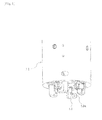
FIG. 1 is an exterior perspective view of the head holding section of embodiment 1 of the present invention as seen diagonally from below. - [
FIG. 2 ]
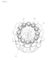
FIG. 2 is an exterior perspective view of the mounting head of embodiment 1 as seen diagonally from above. - [
FIG. 3 ]
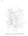
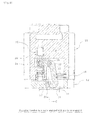
FIG. 3 is a longitudinal section showing the engaging member of the head holding section of embodiment 1 in an engaged state with the pin to be engaged of the mounting head. - [
FIG. 4 ]
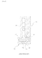
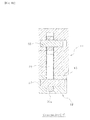
FIG. 4 is a longitudinal section showing the view along the line A-A ofFIG. 3 . - [
FIG. 5 ]
FIG. 5 is a longitudinal section showing the engaging member of head holding section of embodiment 1 in a state lowered to the release position. - [
FIG. 6 ]
FIG. 6 is a longitudinal section showing the view along the line B-B ofFIG. 5 . - [
FIG. 7 ]
FIG. 7 is an exterior perspective view of the head holding of embodiment 2 of the present invention as seen diagonally from below. - [
FIG. 8 ]
FIG. 8 is an exterior perspective view of the mounting head of embodiment 2 as seen diagonally from above. - [
FIG. 9 ]
FIG. 9 is a longitudinal section showing the engaging member of the head holding section of embodiment 2 in an engaged state with the pin to be engaged of the mounting head. - [
FIG. 10 ]
FIG. 10 is a longitudinal section showing the view along the line C-C ofFIG. 9 . - [
FIG. 11 ]
FIG. 11 is a longitudinal section showing the engaging member of head holding section of embodiment 2 in a state rotated to the release position. - The following describes two modes for carrying out the invention, embodiment 1 and embodiment 2.
- This describes embodiment 1 of the present invention based on
FIG. 1 to FIG. 6 . Multiple (for example, four) engagingmembers 13 for detachably engaging and holding mounting head 12 (refer toFIG. 2 ) are provided movably in the up/down direction onhead holding section 11 of the component mounter. Although not shown in the figures,head holding section 11 is configured such that, as well as being capable of being moved in the XYZ directions by an XYZ moving mechanism, is capable of being rotated around the center axis (Z axis) of saidhead holding section 11 by a rotating mechanism. Mountinghead 12 is a rotary head with multiple suction nozzles (not shown in figures) for picking up components arranged in a circumferential direction at predetermined intervals. - Multiple
engaging members 13 are formed respectively as L-shapes or J-shapes and are arranged at even intervals in a circumferential direction with the center axis (Z axis) ofhead holding section 11 as the center, and the direction ofclaw section 13a of eachengaging member 13 is arranged so as to be facing in the same direction as the normal rotational direction (or the reverse rotational direction) ofhead holding section 11. - As shown in
FIG. 2 , multipleelongated holes 16 are formed at even intervals in a circumferential direction on connectingsection 15 for thehead holding section 11 of mountinghead 12 in order for eachengaging member 13 ofhead holding section 11 to pass through, and pin to be engaged 17 which is a member to be engaged that is engaged byclaw section 13a ofengaging member 13 is fixedly penetrating on one side of eachelongated hole 16 in the radial direction of mountinghead 12. To the side of pin to be engaged 17 of eachelongated hole 16, a gap is maintained so thatengaging member 13 can pass by in the up/down direction. - As shown in
FIG. 3 andFIG. 5 ,air cylinders 18 for moving eachengaging member 13 respectively in the up/down direction are provided close to eachengaging member 13 ofhead holding section 11.Engaging member 13 is connected viaarm 20 topiston 19 of eachair cylinder 18,piston 19 is moved up/down and engagingmember 13 moves in the up/down direction, and the uppermost position and lowermost position of that movement stroke are the engagement position and release position respectively. - As shown in
FIG. 3 andFIG. 4 , whenengaging member 13 is raised to the engagement position, mountinghead 12 is in a held state byclaw section 13a ofengaging member 13 hooking from the underneath pin to be engaged 17. Conversely, as shown inFIG. 5 andFIG. 6 , whenengaging member 13 is lowered from the engagement position to the release position,claw section 13a ofengaging member 13 moves under pin to be engaged 17 and the engagement is released. - Spring 21 (elastic member) such as a compression coil spring for biasing
piston 19 in the up direction which is the engagement position direction is provided belowpiston 19 of eachair cylinder 18. Further, it is acceptable to provide the elastic member such as a spring for biasingengaging member 13 in the engagement position direction close to engagingmember 13. The space above and the space belowpiston 19 of eachair cylinder 18 are respectively configured such that it is possible to switch between a state connected to a compressed air supply system for supplying compressed air and a state connected to an exhaust system for exhausting air. - If compressed air is supplied to the space below
piston 19 ofair cylinder 18 with the space abovepiston 19 in a state connected to an exhaust system, as shown inFIG. 3 andFIG. 4 ,piston 19 is pushed up by the pressure of the compressed air and the elastic force ofspring 21 such that engagingmember 13 rises to the engagement position. And, if compressed air is supplied to the space abovepiston 19 with the space belowpiston 19 in a state connected to an exhaust system, as shown inFIG.5 andFIG. 6 ,piston 19 is pushed down against the elastic force ofspring 21 by the pressure of the compressed air such that engagingmember 13 lowers to the release position. - Further, the configuration may be such that negative pressure (vacuum pressure) is supplied instead of compressed air to the space above and the space below
piston 19 of eachair cylinder 18, in which case it is acceptable to supply negative pressure to the space abovepiston 19 when raising engagingmember 13 to the engagement position and to supply negative pressure to the space belowpiston 19 when lowering engagingmember 13 to the release position. - Next, the following describes the usage method of the mounting head holding device of the above configuration. When attaching mounting
head 12 to head holdingsection 11, together with movinghead holding section 11 above mountinghead 12 loaded in the mounting head exchange station of the component mounter,piston 19 ofair cylinder 18 is pushed down against the elastic force ofspring 21 such that engagingmember 13 is held in a state lowered to the release position, andhead holding section 11 is rotated to a position in which it is possible forclaw section 13a of engagingmember 13 to pass by the side of pin to be engaged 17. In this state, after loweringhead holding section 11 to be facing mountinghead 12 withclaw section 13a of engagingmember 13 lowered to be lower than pin to be engaged 17,head holding section 11 is rotated and, as shown inFIG. 5 andFIG. 6 , claw 13a of engagingmember 13 is made to be in a position below pin to be engaged 17. After this, as shown inFIG. 3 andFIG. 4 ,claw section 13a of engagingmember 13 is engaged withpin 17 to be engaged by raisingpiston 19 ofair cylinder 18 and raising engagingmember 13 to the engagement position. By this, mountinghead 12 becomes attached to head holdingsection 11. - Conversely, when detaching mounting
head 12 fromhead holding section 11, after movinghead holding section 11 above mounting head exchange station andloading mounting head 12 held byhead holding section 11 into the mounting head exchange station, as shown inFIG. 5 andFIG. 6 ,piston 19 ofair cylinder 18 is pushed down against the elastic force ofspring 21 such that engagingmember 13 is lowered to the release position and clawsection 13a of engagingmember 13 is made to be separated from pin to be engaged 17 on the lower side. In this state,head holding section 11 is raised afterhead holding section 11 is rotated to a position in which engagingmember 13 can pass by the side of pin to be engaged 17. By this, mountinghead 12 is detached fromhead holding section 11 and remains in the mounting head exchange station. - With embodiment 1 described above, because the configuration is such that mounting
head 12 is held mechanically onhead holding section 11 by engagingmember 13 ofhead holding section 11 being engaged with pin to be engaged 17 of mountinghead 12, the holding power of mountinghead 12 can be increased more than conventional negative pressure attachment power, and it is possible to prevent mountinghead 12 which is detachably held to head holdingsection 11 from deviating positionally or falling off even when electricity is not being supplied. - Next, this describes embodiment 2 of the present invention based on
FIG. 7 to FIG. 11 . However, for sections which are practically the same as embodiment 1, the same symbols are used and explanations are omitted or abbreviated, with the sections which are largely different being described. - In embodiment 1 above, the configuration was such that multiple engaging
members 13 were provided onhead holding section 11 capable of being moved up and down, but with embodiment 2 shown inFIG. 7 to FIG. 11 , multiple engagingmembers 31 are provided onhead holding section 11 capable of being rotated in a perpendicular direction to pin to be engaged 17 viarotational axis 32, with one direction (the pin to be engaged 17 side) position and another direction position of that rotation stroke being the engagement position and release position respectively. Each engagingmember 31 is formed as a whole in a roughly chevron shape, with the bend section thereof penetrated byrotational axis 32, with the lower section of engagingmember 31 formed in an L-shape or J-shape, the tip of which isclaw section 31a for engaging with pin to be engaged 17, and with the upper section of engagingmember 31 extending aboveair cylinder 18, in the tip of which is formedelongated hole 33, with thiselongated hole 33 engaged in a freely sliding manner with fixedpin 34 which is fixed topiston 19 ofair cylinder 18. By this, engagingmember 31 is rotated between the engagement position and the release position by movingpiston 19 ofair cylinder 18 up/down.Spring 35 such as a torsion coil spring which is an elastic member for biasing engagingmember 31 in the direction of the engagement position is provided onhead holding section 11 close to each engagingmember 31. Further, it is acceptable to provide the elastic member such as a spring for biasing engagingmember 31 in the engagement position direction insideair cylinder 18. - Next, the following describes the usage method of the mounting head holding device of the above configuration. When attaching mounting
head 12 to head holdingsection 11, together with movinghead holding section 11 above mountinghead 12 loaded in the mounting head exchange station of the component mounter, as shown inFIG. 11 ,piston 19 ofair cylinder 18 is pushed down against the elastic force ofspring 35 such that engagingmember 31 is held in a state rotated to the release position. In this state, after loweringhead holding section 11 to be facing mountinghead 12, as shown inFIG. 9 ,claw section 31a of engagingmember 31 is engaged with pin to be engaged 17 by raisingpiston 19 ofair cylinder 18 and rotating engagingmember 31 to the engagement position. By this, mountinghead 12 becomes attached to head holdingsection 11. - Conversely, when detaching mounting
head 12 fromhead holding section 11, after movinghead holding section 11 above the mounting head exchange station andloading mounting head 12 held byhead holding section 11 into the mounting head exchange station, as shown inFIG. 11 , afterpiston 19 ofair cylinder 18 is pushed down such that engagingmember 31 is held in a state rotated to the release position against the elastic force ofspring 35,head holding section 11 is raised. By this, mountinghead 12 is detached fromhead holding section 11 and remains in the mounting head exchange station. - With embodiment 2 described above, when attaching/detaching mounting
head 12 to/fromhead holding section 11, even ifhead holding section 11 is not rotated with respect to mountinghead 12, if engagingmember 31 ofhead holding section 11 is held in a state rotated to the release position, it is possible for engagingmember 31 ofhead holding section 11 to pass by the side of pin to be engaged 17 of mountinghead 12, and the attachability/detachability of mountinghead 12 can be improved. - Further, mounting
head 12 which is detachably held to head holdingsection 11 is not limited to being a rotary head, and may be a mounting head with only one large suction nozzle attached, or a mounting head with a chuck for grabbing components attached. - In addition, the present invention may be embodied with various changes that do not extend beyond the scope of the invention, such as changing the quantity of engaging members and members to be engaged, or changing the form of the engaging members and members to be engaged.
- 11: Head holding section; 12: Mounting head; 13: Engaging member; 13a: Claw section; 15: Connecting section; 16: Elongated hole; 17: Pin to be engaged (member to be engaged); 18: Air cylinder; 19: Piston; 21: Spring (elastic means); 31: Engaging member; 31a: Claw section; 32: Rotating axis; 33: Elongated hole; 34: Fixed pin; 35: Spring (elastic means)
Claims (6)
- A component mounter mounting head holding device for detachably holding a mounting head which mounts components to a circuit board to a head holding section of a component mounter, comprising: a member to be engaged provided on a connecting section for the head holding section of the mounting head; an engaging member provided on the head holding section which moves between an engagement position for holding the mounting head in which the engaging member is engaged with the member to be engaged and a release position in which the engaging member is separated from the member to be engaged; and an air cylinder provided on the head holding section which is the power source for moving the engaging member between the engagement position and the release position.
- The component mounter mounting head holding device from Claim 1 characterized in that the engaging member is formed in an L-shape or J-shape which hooks from underneath and holds the member to be engaged.
- The component mounter mounting head holding device from Claim 1 or Claim 2 characterized in that the engaging member is provided so that it is capable of being moved up and down with the configuration such that the uppermost position and lowermost position of that movement stroke are the engagement position and release position respectively; and when attaching the mounting head to the head holding section, together with holding the engaging member in the release position using the air cylinder and having the head holding section rotated to a position in which the engaging member can pass by the side of the member to be engaged, the head holding section is lowered so that it is face-to-face with the mounting head, and then, by raising the engaging member to the engagement position using the air cylinder after rotating the head holding section so that the lower section of the engaging member is below the member to be engaged, the engaging member is engaged with the member to be engaged thereby attaching the mounting head to the head holding section; and when detaching the mounting head from the head holding section, the head holding section is rotated to a position in which the engaging member can pass by the side of the member to be engaged after lowering the engaging member to the release position using the air cylinder, and then the mounting head is detached from the head holding section by raising the head holding section.
- The component mounter mounting head holding device from Claim 1 or Claim 2 characterized in that the engaging member is provided so that it is capable of being rotated around a rotating axis with the configuration such that one direction position of that rotation stroke and another direction position thereof are the engagement position and release position respectively; and when attaching the mounting head to the head holding section, with the engaging member held in the release position using the air cylinder, the head holding section is lowered so that it is face-to-face with the mounting head, and then, the engaging member is engaged with the member to be engaged by rotating the engaging member to the engagement position using the air cylinder, thereby attaching the mounting head to the head holding section; and when detaching the mounting head from the head holding section, after having rotated the engaging member to the release position using the air cylinder, the mounting head is detached from the head holding section by raising the head holding section.
- The component mounter mounting head holding device according to any of claims 1 to 4 characterized in that an elastic member for biasing the engaging member in the engagement position direction is provided on the head holding section.
- The component mounter mounting head holding device according to any of claims 1 to 5 characterized in that the mounting head is a rotary head with multiple suction nozzles for picking up components arranged in a circumferential direction at predetermined intervals.
Applications Claiming Priority (1)
| Application Number | Priority Date | Filing Date | Title |
|---|---|---|---|
| PCT/JP2012/051203 WO2013108394A1 (en) | 2012-01-20 | 2012-01-20 | Mounting head holding device for component mounting machine |
Publications (3)
| Publication Number | Publication Date |
|---|---|
| EP2806719A1 true EP2806719A1 (en) | 2014-11-26 |
| EP2806719A4 EP2806719A4 (en) | 2015-07-01 |
| EP2806719B1 EP2806719B1 (en) | 2019-03-13 |
Family
ID=48798840
Family Applications (1)
| Application Number | Title | Priority Date | Filing Date |
|---|---|---|---|
| EP12866384.6A Active EP2806719B1 (en) | 2012-01-20 | 2012-01-20 | Mounting head holding device for component mounting machine |
Country Status (5)
| Country | Link |
|---|---|
| US (1) | US9677588B2 (en) |
| EP (1) | EP2806719B1 (en) |
| JP (1) | JP5808063B2 (en) |
| CN (1) | CN104081888B (en) |
| WO (1) | WO2013108394A1 (en) |
Families Citing this family (7)
| Publication number | Priority date | Publication date | Assignee | Title |
|---|---|---|---|---|
| JP6246212B2 (en) * | 2013-08-08 | 2017-12-13 | 富士機械製造株式会社 | Component mounter |
| EP3051935B1 (en) * | 2013-09-25 | 2018-08-22 | Fuji Machine Mfg. Co., Ltd. | Component mounting apparatus |
| JP6438043B2 (en) * | 2014-10-31 | 2018-12-12 | 株式会社Fuji | Component mounter and nozzle tool used therefor |
| JP6378054B2 (en) * | 2014-11-12 | 2018-08-22 | 株式会社Fuji | Tool mounting device for component mounter and nozzle tool for component mounter |
| JP6762528B2 (en) * | 2016-04-28 | 2020-09-30 | 株式会社Fuji | Parts mounting machine and nozzle tool used for it |
| JP7121143B2 (en) * | 2018-12-28 | 2022-08-17 | 株式会社Fuji | Working head and working machine |
| JP7300606B2 (en) * | 2019-10-25 | 2023-06-30 | 株式会社Fuji | Mounting machine |
Family Cites Families (8)
| Publication number | Priority date | Publication date | Assignee | Title |
|---|---|---|---|---|
| US4664588A (en) * | 1984-03-09 | 1987-05-12 | Applied Robotics Inc. | Apparatus and method for connecting and exchanging remote manipulable elements to a central control source |
| DE3433311A1 (en) * | 1984-09-11 | 1986-03-20 | C. & E. Fein Gmbh & Co, 7000 Stuttgart | TOOL CHANGE DEVICE FOR INDUSTRIAL ROBOTS |
| JPS63123683A (en) * | 1986-11-10 | 1988-05-27 | 三菱電機株式会社 | Part sucking conveyor |
| JP2792931B2 (en) * | 1989-08-25 | 1998-09-03 | 三洋電機株式会社 | Electronic component mounting device |
| JPH0748384Y2 (en) * | 1990-07-11 | 1995-11-08 | 株式会社安川電機 | Robot tool changer |
| KR930006593B1 (en) * | 1990-10-20 | 1993-07-21 | 현대 전자 산업 주식회사 | Semiconductor lead frame loader head unit |
| JP4391290B2 (en) * | 2004-03-30 | 2009-12-24 | パナソニック株式会社 | Rotary type component mounting equipment |
| JP4546857B2 (en) | 2005-03-16 | 2010-09-22 | 富士機械製造株式会社 | Electronic component holding device and electronic component mounting system |
-
2012
- 2012-01-20 US US14/372,326 patent/US9677588B2/en not_active Expired - Fee Related
- 2012-01-20 JP JP2013554160A patent/JP5808063B2/en active Active
- 2012-01-20 CN CN201280067533.0A patent/CN104081888B/en not_active Expired - Fee Related
- 2012-01-20 WO PCT/JP2012/051203 patent/WO2013108394A1/en not_active Ceased
- 2012-01-20 EP EP12866384.6A patent/EP2806719B1/en active Active
Also Published As
| Publication number | Publication date |
|---|---|
| WO2013108394A1 (en) | 2013-07-25 |
| US20140328617A1 (en) | 2014-11-06 |
| JPWO2013108394A1 (en) | 2015-05-11 |
| EP2806719A4 (en) | 2015-07-01 |
| EP2806719B1 (en) | 2019-03-13 |
| CN104081888B (en) | 2016-10-12 |
| US9677588B2 (en) | 2017-06-13 |
| CN104081888A (en) | 2014-10-01 |
| JP5808063B2 (en) | 2015-11-10 |
Similar Documents
| Publication | Publication Date | Title |
|---|---|---|
| EP2806719B1 (en) | Mounting head holding device for component mounting machine | |
| EP2892312B1 (en) | Component mounting machine | |
| EP3026996B1 (en) | Component mounting machine | |
| CN212824928U (en) | Carrier replacing equipment | |
| EP3264878B1 (en) | Component mounter | |
| JP2009218463A (en) | Nozzle recovery device, mounting device equipped with nozzle recovery device, and maintenance of recovery nozzle | |
| JPWO2014045377A1 (en) | Bulk component supply device and component mounting device | |
| CN211894904U (en) | Feeding and discharging rotary manipulator | |
| KR20130051866A (en) | A system for exchanging capillary automatically | |
| WO2013140915A1 (en) | Pair circuit board work machine | |
| CN210042737U (en) | Plug-in robot | |
| CN207189697U (en) | A kind of anti-slip cramping apparatus of catching robot | |
| CN111410037A (en) | Automatic grabbing device of flexible work piece | |
| CN211422553U (en) | Drilling machine | |
| JP6246212B2 (en) | Component mounter | |
| CN203682597U (en) | Automatic picking-storing device for picking and storing automotive brake discs and hubs | |
| CN106914597A (en) | Magneto inserts gripper equipment | |
| JP3254260U (en) | Gripper Changer | |
| CN206643320U (en) | Magneto inserts gripper equipment | |
| CN115579794B (en) | Automated ground wire connection device for high-voltage line construction | |
| JP5997631B2 (en) | Tire bead removal device | |
| CN111590554A (en) | Mechanical arm | |
| JP5109924B2 (en) | Electronic component mounting equipment | |
| CN211758306U (en) | Automatic rivet pulling machine | |
| JP5980945B2 (en) | Component mounter |
Legal Events
| Date | Code | Title | Description |
|---|---|---|---|
| PUAI | Public reference made under article 153(3) epc to a published international application that has entered the european phase |
Free format text: ORIGINAL CODE: 0009012 |
|
| 17P | Request for examination filed |
Effective date: 20140527 |
|
| AK | Designated contracting states |
Kind code of ref document: A1 Designated state(s): AL AT BE BG CH CY CZ DE DK EE ES FI FR GB GR HR HU IE IS IT LI LT LU LV MC MK MT NL NO PL PT RO RS SE SI SK SM TR |
|
| DAX | Request for extension of the european patent (deleted) | ||
| RA4 | Supplementary search report drawn up and despatched (corrected) |
Effective date: 20150603 |
|
| RIC1 | Information provided on ipc code assigned before grant |
Ipc: H05K 13/04 20060101AFI20150528BHEP |
|
| STAA | Information on the status of an ep patent application or granted ep patent |
Free format text: STATUS: EXAMINATION IS IN PROGRESS |
|
| 17Q | First examination report despatched |
Effective date: 20180607 |
|
| RAP1 | Party data changed (applicant data changed or rights of an application transferred) |
Owner name: FUJI CORPORATION |
|
| GRAP | Despatch of communication of intention to grant a patent |
Free format text: ORIGINAL CODE: EPIDOSNIGR1 |
|
| STAA | Information on the status of an ep patent application or granted ep patent |
Free format text: STATUS: GRANT OF PATENT IS INTENDED |
|
| INTG | Intention to grant announced |
Effective date: 20181115 |
|
| GRAS | Grant fee paid |
Free format text: ORIGINAL CODE: EPIDOSNIGR3 |
|
| RIN1 | Information on inventor provided before grant (corrected) |
Inventor name: NISHIYAMA, SATORU |
|
| GRAA | (expected) grant |
Free format text: ORIGINAL CODE: 0009210 |
|
| STAA | Information on the status of an ep patent application or granted ep patent |
Free format text: STATUS: THE PATENT HAS BEEN GRANTED |
|
| AK | Designated contracting states |
Kind code of ref document: B1 Designated state(s): AL AT BE BG CH CY CZ DE DK EE ES FI FR GB GR HR HU IE IS IT LI LT LU LV MC MK MT NL NO PL PT RO RS SE SI SK SM TR |
|
| REG | Reference to a national code |
Ref country code: GB Ref legal event code: FG4D |
|
| REG | Reference to a national code |
Ref country code: CH Ref legal event code: EP Ref country code: AT Ref legal event code: REF Ref document number: 1109500 Country of ref document: AT Kind code of ref document: T Effective date: 20190315 |
|
| REG | Reference to a national code |
Ref country code: IE Ref legal event code: FG4D |
|
| REG | Reference to a national code |
Ref country code: DE Ref legal event code: R096 Ref document number: 602012057899 Country of ref document: DE |
|
| REG | Reference to a national code |
Ref country code: NL Ref legal event code: MP Effective date: 20190313 |
|
| REG | Reference to a national code |
Ref country code: LT Ref legal event code: MG4D |
|
| PG25 | Lapsed in a contracting state [announced via postgrant information from national office to epo] |
Ref country code: LT Free format text: LAPSE BECAUSE OF FAILURE TO SUBMIT A TRANSLATION OF THE DESCRIPTION OR TO PAY THE FEE WITHIN THE PRESCRIBED TIME-LIMIT Effective date: 20190313 Ref country code: SE Free format text: LAPSE BECAUSE OF FAILURE TO SUBMIT A TRANSLATION OF THE DESCRIPTION OR TO PAY THE FEE WITHIN THE PRESCRIBED TIME-LIMIT Effective date: 20190313 Ref country code: NO Free format text: LAPSE BECAUSE OF FAILURE TO SUBMIT A TRANSLATION OF THE DESCRIPTION OR TO PAY THE FEE WITHIN THE PRESCRIBED TIME-LIMIT Effective date: 20190613 Ref country code: FI Free format text: LAPSE BECAUSE OF FAILURE TO SUBMIT A TRANSLATION OF THE DESCRIPTION OR TO PAY THE FEE WITHIN THE PRESCRIBED TIME-LIMIT Effective date: 20190313 |
|
| PG25 | Lapsed in a contracting state [announced via postgrant information from national office to epo] |
Ref country code: RS Free format text: LAPSE BECAUSE OF FAILURE TO SUBMIT A TRANSLATION OF THE DESCRIPTION OR TO PAY THE FEE WITHIN THE PRESCRIBED TIME-LIMIT Effective date: 20190313 Ref country code: NL Free format text: LAPSE BECAUSE OF FAILURE TO SUBMIT A TRANSLATION OF THE DESCRIPTION OR TO PAY THE FEE WITHIN THE PRESCRIBED TIME-LIMIT Effective date: 20190313 Ref country code: BG Free format text: LAPSE BECAUSE OF FAILURE TO SUBMIT A TRANSLATION OF THE DESCRIPTION OR TO PAY THE FEE WITHIN THE PRESCRIBED TIME-LIMIT Effective date: 20190613 Ref country code: LV Free format text: LAPSE BECAUSE OF FAILURE TO SUBMIT A TRANSLATION OF THE DESCRIPTION OR TO PAY THE FEE WITHIN THE PRESCRIBED TIME-LIMIT Effective date: 20190313 Ref country code: GR Free format text: LAPSE BECAUSE OF FAILURE TO SUBMIT A TRANSLATION OF THE DESCRIPTION OR TO PAY THE FEE WITHIN THE PRESCRIBED TIME-LIMIT Effective date: 20190614 Ref country code: HR Free format text: LAPSE BECAUSE OF FAILURE TO SUBMIT A TRANSLATION OF THE DESCRIPTION OR TO PAY THE FEE WITHIN THE PRESCRIBED TIME-LIMIT Effective date: 20190313 |
|
| REG | Reference to a national code |
Ref country code: AT Ref legal event code: MK05 Ref document number: 1109500 Country of ref document: AT Kind code of ref document: T Effective date: 20190313 |
|
| PG25 | Lapsed in a contracting state [announced via postgrant information from national office to epo] |
Ref country code: EE Free format text: LAPSE BECAUSE OF FAILURE TO SUBMIT A TRANSLATION OF THE DESCRIPTION OR TO PAY THE FEE WITHIN THE PRESCRIBED TIME-LIMIT Effective date: 20190313 Ref country code: IT Free format text: LAPSE BECAUSE OF FAILURE TO SUBMIT A TRANSLATION OF THE DESCRIPTION OR TO PAY THE FEE WITHIN THE PRESCRIBED TIME-LIMIT Effective date: 20190313 Ref country code: SK Free format text: LAPSE BECAUSE OF FAILURE TO SUBMIT A TRANSLATION OF THE DESCRIPTION OR TO PAY THE FEE WITHIN THE PRESCRIBED TIME-LIMIT Effective date: 20190313 Ref country code: PT Free format text: LAPSE BECAUSE OF FAILURE TO SUBMIT A TRANSLATION OF THE DESCRIPTION OR TO PAY THE FEE WITHIN THE PRESCRIBED TIME-LIMIT Effective date: 20190713 Ref country code: AL Free format text: LAPSE BECAUSE OF FAILURE TO SUBMIT A TRANSLATION OF THE DESCRIPTION OR TO PAY THE FEE WITHIN THE PRESCRIBED TIME-LIMIT Effective date: 20190313 Ref country code: ES Free format text: LAPSE BECAUSE OF FAILURE TO SUBMIT A TRANSLATION OF THE DESCRIPTION OR TO PAY THE FEE WITHIN THE PRESCRIBED TIME-LIMIT Effective date: 20190313 Ref country code: CZ Free format text: LAPSE BECAUSE OF FAILURE TO SUBMIT A TRANSLATION OF THE DESCRIPTION OR TO PAY THE FEE WITHIN THE PRESCRIBED TIME-LIMIT Effective date: 20190313 Ref country code: RO Free format text: LAPSE BECAUSE OF FAILURE TO SUBMIT A TRANSLATION OF THE DESCRIPTION OR TO PAY THE FEE WITHIN THE PRESCRIBED TIME-LIMIT Effective date: 20190313 |
|
| PG25 | Lapsed in a contracting state [announced via postgrant information from national office to epo] |
Ref country code: SM Free format text: LAPSE BECAUSE OF FAILURE TO SUBMIT A TRANSLATION OF THE DESCRIPTION OR TO PAY THE FEE WITHIN THE PRESCRIBED TIME-LIMIT Effective date: 20190313 Ref country code: PL Free format text: LAPSE BECAUSE OF FAILURE TO SUBMIT A TRANSLATION OF THE DESCRIPTION OR TO PAY THE FEE WITHIN THE PRESCRIBED TIME-LIMIT Effective date: 20190313 |
|
| REG | Reference to a national code |
Ref country code: DE Ref legal event code: R097 Ref document number: 602012057899 Country of ref document: DE |
|
| PG25 | Lapsed in a contracting state [announced via postgrant information from national office to epo] |
Ref country code: AT Free format text: LAPSE BECAUSE OF FAILURE TO SUBMIT A TRANSLATION OF THE DESCRIPTION OR TO PAY THE FEE WITHIN THE PRESCRIBED TIME-LIMIT Effective date: 20190313 Ref country code: IS Free format text: LAPSE BECAUSE OF FAILURE TO SUBMIT A TRANSLATION OF THE DESCRIPTION OR TO PAY THE FEE WITHIN THE PRESCRIBED TIME-LIMIT Effective date: 20190713 |
|
| PLBE | No opposition filed within time limit |
Free format text: ORIGINAL CODE: 0009261 |
|
| STAA | Information on the status of an ep patent application or granted ep patent |
Free format text: STATUS: NO OPPOSITION FILED WITHIN TIME LIMIT |
|
| PG25 | Lapsed in a contracting state [announced via postgrant information from national office to epo] |
Ref country code: DK Free format text: LAPSE BECAUSE OF FAILURE TO SUBMIT A TRANSLATION OF THE DESCRIPTION OR TO PAY THE FEE WITHIN THE PRESCRIBED TIME-LIMIT Effective date: 20190313 |
|
| 26N | No opposition filed |
Effective date: 20191216 |
|
| PG25 | Lapsed in a contracting state [announced via postgrant information from national office to epo] |
Ref country code: SI Free format text: LAPSE BECAUSE OF FAILURE TO SUBMIT A TRANSLATION OF THE DESCRIPTION OR TO PAY THE FEE WITHIN THE PRESCRIBED TIME-LIMIT Effective date: 20190313 |
|
| PG25 | Lapsed in a contracting state [announced via postgrant information from national office to epo] |
Ref country code: TR Free format text: LAPSE BECAUSE OF FAILURE TO SUBMIT A TRANSLATION OF THE DESCRIPTION OR TO PAY THE FEE WITHIN THE PRESCRIBED TIME-LIMIT Effective date: 20190313 |
|
| PG25 | Lapsed in a contracting state [announced via postgrant information from national office to epo] |
Ref country code: MC Free format text: LAPSE BECAUSE OF FAILURE TO SUBMIT A TRANSLATION OF THE DESCRIPTION OR TO PAY THE FEE WITHIN THE PRESCRIBED TIME-LIMIT Effective date: 20190313 |
|
| REG | Reference to a national code |
Ref country code: CH Ref legal event code: PL |
|
| GBPC | Gb: european patent ceased through non-payment of renewal fee |
Effective date: 20200120 |
|
| REG | Reference to a national code |
Ref country code: BE Ref legal event code: MM Effective date: 20200131 |
|
| PG25 | Lapsed in a contracting state [announced via postgrant information from national office to epo] |
Ref country code: FR Free format text: LAPSE BECAUSE OF NON-PAYMENT OF DUE FEES Effective date: 20200131 Ref country code: GB Free format text: LAPSE BECAUSE OF NON-PAYMENT OF DUE FEES Effective date: 20200120 Ref country code: LU Free format text: LAPSE BECAUSE OF NON-PAYMENT OF DUE FEES Effective date: 20200120 |
|
| PG25 | Lapsed in a contracting state [announced via postgrant information from national office to epo] |
Ref country code: CH Free format text: LAPSE BECAUSE OF NON-PAYMENT OF DUE FEES Effective date: 20200131 Ref country code: LI Free format text: LAPSE BECAUSE OF NON-PAYMENT OF DUE FEES Effective date: 20200131 Ref country code: BE Free format text: LAPSE BECAUSE OF NON-PAYMENT OF DUE FEES Effective date: 20200131 |
|
| PG25 | Lapsed in a contracting state [announced via postgrant information from national office to epo] |
Ref country code: IE Free format text: LAPSE BECAUSE OF NON-PAYMENT OF DUE FEES Effective date: 20200120 |
|
| PG25 | Lapsed in a contracting state [announced via postgrant information from national office to epo] |
Ref country code: MT Free format text: LAPSE BECAUSE OF FAILURE TO SUBMIT A TRANSLATION OF THE DESCRIPTION OR TO PAY THE FEE WITHIN THE PRESCRIBED TIME-LIMIT Effective date: 20190313 Ref country code: CY Free format text: LAPSE BECAUSE OF FAILURE TO SUBMIT A TRANSLATION OF THE DESCRIPTION OR TO PAY THE FEE WITHIN THE PRESCRIBED TIME-LIMIT Effective date: 20190313 |
|
| PG25 | Lapsed in a contracting state [announced via postgrant information from national office to epo] |
Ref country code: MK Free format text: LAPSE BECAUSE OF FAILURE TO SUBMIT A TRANSLATION OF THE DESCRIPTION OR TO PAY THE FEE WITHIN THE PRESCRIBED TIME-LIMIT Effective date: 20190313 |
|
| P01 | Opt-out of the competence of the unified patent court (upc) registered |
Effective date: 20230328 |
|
| PGFP | Annual fee paid to national office [announced via postgrant information from national office to epo] |
Ref country code: DE Payment date: 20231128 Year of fee payment: 13 |
|
| REG | Reference to a national code |
Ref country code: DE Ref legal event code: R119 Ref document number: 602012057899 Country of ref document: DE |
|
| PG25 | Lapsed in a contracting state [announced via postgrant information from national office to epo] |
Ref country code: DE Free format text: LAPSE BECAUSE OF NON-PAYMENT OF DUE FEES Effective date: 20250801 |