EP2806592B1 - Procédé et appareil pour fonctionnement à base de canal de commande amélioré dans un système de communication sans fil - Google Patents
Procédé et appareil pour fonctionnement à base de canal de commande amélioré dans un système de communication sans fil Download PDFInfo
- Publication number
- EP2806592B1 EP2806592B1 EP13739007.6A EP13739007A EP2806592B1 EP 2806592 B1 EP2806592 B1 EP 2806592B1 EP 13739007 A EP13739007 A EP 13739007A EP 2806592 B1 EP2806592 B1 EP 2806592B1
- Authority
- EP
- European Patent Office
- Prior art keywords
- index
- pdcch
- control channel
- pucch
- ack
- Prior art date
- Legal status (The legal status is an assumption and is not a legal conclusion. Google has not performed a legal analysis and makes no representation as to the accuracy of the status listed.)
- Active
Links
- 238000000034 method Methods 0.000 title claims description 108
- 238000004891 communication Methods 0.000 title claims description 16
- 101000741965 Homo sapiens Inactive tyrosine-protein kinase PRAG1 Proteins 0.000 claims description 175
- 102100038659 Inactive tyrosine-protein kinase PRAG1 Human genes 0.000 claims description 175
- 230000011664 signaling Effects 0.000 claims description 14
- 230000007774 longterm Effects 0.000 claims description 6
- 230000005540 biological transmission Effects 0.000 description 115
- 230000002776 aggregation Effects 0.000 description 42
- 238000004220 aggregation Methods 0.000 description 42
- 230000006870 function Effects 0.000 description 13
- 230000004044 response Effects 0.000 description 12
- 238000010586 diagram Methods 0.000 description 11
- 101001056707 Homo sapiens Proepiregulin Proteins 0.000 description 8
- 102100025498 Proepiregulin Human genes 0.000 description 8
- 238000001514 detection method Methods 0.000 description 8
- 238000013507 mapping Methods 0.000 description 8
- 101150055297 SET1 gene Proteins 0.000 description 6
- 101150117538 Set2 gene Proteins 0.000 description 5
- 238000004364 calculation method Methods 0.000 description 5
- 125000004122 cyclic group Chemical group 0.000 description 5
- 239000000470 constituent Substances 0.000 description 4
- 238000005516 engineering process Methods 0.000 description 4
- 238000012545 processing Methods 0.000 description 4
- 238000013468 resource allocation Methods 0.000 description 4
- 238000012544 monitoring process Methods 0.000 description 3
- 239000013256 coordination polymer Substances 0.000 description 2
- 230000000694 effects Effects 0.000 description 2
- 238000010295 mobile communication Methods 0.000 description 2
- 230000008569 process Effects 0.000 description 2
- 101150071746 Pbsn gene Proteins 0.000 description 1
- 230000004913 activation Effects 0.000 description 1
- 238000003491 array Methods 0.000 description 1
- 239000000969 carrier Substances 0.000 description 1
- 230000001413 cellular effect Effects 0.000 description 1
- 230000008859 change Effects 0.000 description 1
- 238000007796 conventional method Methods 0.000 description 1
- 230000003247 decreasing effect Effects 0.000 description 1
- 238000007726 management method Methods 0.000 description 1
- 239000011159 matrix material Substances 0.000 description 1
- 230000007480 spreading Effects 0.000 description 1
Images


Classifications
-
- H—ELECTRICITY
- H04—ELECTRIC COMMUNICATION TECHNIQUE
- H04B—TRANSMISSION
- H04B7/00—Radio transmission systems, i.e. using radiation field
- H04B7/02—Diversity systems; Multi-antenna system, i.e. transmission or reception using multiple antennas
- H04B7/04—Diversity systems; Multi-antenna system, i.e. transmission or reception using multiple antennas using two or more spaced independent antennas
- H04B7/0413—MIMO systems
- H04B7/0452—Multi-user MIMO systems
-
- H—ELECTRICITY
- H04—ELECTRIC COMMUNICATION TECHNIQUE
- H04L—TRANSMISSION OF DIGITAL INFORMATION, e.g. TELEGRAPHIC COMMUNICATION
- H04L1/00—Arrangements for detecting or preventing errors in the information received
- H04L1/12—Arrangements for detecting or preventing errors in the information received by using return channel
- H04L1/16—Arrangements for detecting or preventing errors in the information received by using return channel in which the return channel carries supervisory signals, e.g. repetition request signals
- H04L1/18—Automatic repetition systems, e.g. Van Duuren systems
- H04L1/1829—Arrangements specially adapted for the receiver end
- H04L1/1861—Physical mapping arrangements
-
- H—ELECTRICITY
- H04—ELECTRIC COMMUNICATION TECHNIQUE
- H04L—TRANSMISSION OF DIGITAL INFORMATION, e.g. TELEGRAPHIC COMMUNICATION
- H04L1/00—Arrangements for detecting or preventing errors in the information received
- H04L1/12—Arrangements for detecting or preventing errors in the information received by using return channel
- H04L1/16—Arrangements for detecting or preventing errors in the information received by using return channel in which the return channel carries supervisory signals, e.g. repetition request signals
- H04L1/18—Automatic repetition systems, e.g. Van Duuren systems
- H04L1/1867—Arrangements specially adapted for the transmitter end
- H04L1/1896—ARQ related signaling
-
- H—ELECTRICITY
- H04—ELECTRIC COMMUNICATION TECHNIQUE
- H04L—TRANSMISSION OF DIGITAL INFORMATION, e.g. TELEGRAPHIC COMMUNICATION
- H04L5/00—Arrangements affording multiple use of the transmission path
- H04L5/0001—Arrangements for dividing the transmission path
- H04L5/0014—Three-dimensional division
- H04L5/0023—Time-frequency-space
-
- H—ELECTRICITY
- H04—ELECTRIC COMMUNICATION TECHNIQUE
- H04L—TRANSMISSION OF DIGITAL INFORMATION, e.g. TELEGRAPHIC COMMUNICATION
- H04L5/00—Arrangements affording multiple use of the transmission path
- H04L5/003—Arrangements for allocating sub-channels of the transmission path
- H04L5/0048—Allocation of pilot signals, i.e. of signals known to the receiver
-
- H—ELECTRICITY
- H04—ELECTRIC COMMUNICATION TECHNIQUE
- H04L—TRANSMISSION OF DIGITAL INFORMATION, e.g. TELEGRAPHIC COMMUNICATION
- H04L5/00—Arrangements affording multiple use of the transmission path
- H04L5/003—Arrangements for allocating sub-channels of the transmission path
- H04L5/0053—Allocation of signaling, i.e. of overhead other than pilot signals
- H04L5/0055—Physical resource allocation for ACK/NACK
-
- H—ELECTRICITY
- H04—ELECTRIC COMMUNICATION TECHNIQUE
- H04L—TRANSMISSION OF DIGITAL INFORMATION, e.g. TELEGRAPHIC COMMUNICATION
- H04L5/00—Arrangements affording multiple use of the transmission path
- H04L5/0091—Signaling for the administration of the divided path
- H04L5/0092—Indication of how the channel is divided
-
- H—ELECTRICITY
- H04—ELECTRIC COMMUNICATION TECHNIQUE
- H04W—WIRELESS COMMUNICATION NETWORKS
- H04W72/00—Local resource management
- H04W72/20—Control channels or signalling for resource management
-
- H—ELECTRICITY
- H04—ELECTRIC COMMUNICATION TECHNIQUE
- H04W—WIRELESS COMMUNICATION NETWORKS
- H04W72/00—Local resource management
- H04W72/20—Control channels or signalling for resource management
- H04W72/21—Control channels or signalling for resource management in the uplink direction of a wireless link, i.e. towards the network
-
- H—ELECTRICITY
- H04—ELECTRIC COMMUNICATION TECHNIQUE
- H04W—WIRELESS COMMUNICATION NETWORKS
- H04W72/00—Local resource management
- H04W72/20—Control channels or signalling for resource management
- H04W72/23—Control channels or signalling for resource management in the downlink direction of a wireless link, i.e. towards a terminal
Definitions
- the present invention relates to a wireless communication system, and more particularly, to a method and apparatus for an enhanced-control channel-based operation.
- a user equipment detects a downlink (DL) control channel for carrying scheduling information about DL data transmission and accordingly receives DL data from an eNB.
- the UE generates acknowledgement/negative-acknowledgement (ACK/NACK) information indicating whether decoding of DL data is successful and transmits the ACK/NACK information to the eNB.
- DL downlink
- ACK/NACK acknowledgement/negative-acknowledgement
- a resource used for transmission of ACK/NACK information may be determined from a DL control channel for carrying the DL scheduling information.
- the DL control channel is transmitted based on an antenna port of a cell-specific reference signal, and a UE detects and demodulates the DL control channel based on an estimated channel using an antenna port of the cell-specific reference signal.
- Document WO 2011/136584 A2 describes a technique for transmitting ACK/NACK signals. Values specifically defined for each user equipment are reflected when allocating ACK/NACK channels. When signals for a plurality of user equipments are transmitted from the same resource, the ACK/NACK signals of the plurality of user equipments are transmitted from different resources, thereby reducing interference.
- Document EP 2 383 928 A2 describes a technique for resource mapping.
- an uplink ACK/NACK channel associated with the control channel is extended by spatial multiplexing into the uplink ACK/NACK channel resource which does not support spatial multiplexing.
- an enhanced physical downlink control channel may be used.
- the E-PDCCH may be transmitted based on a demodulation reference (DMRS) but not a cell-specific reference signal and may support multi-user multiple input multiple output (MU-MIMO).
- DMRS demodulation reference
- MU-MIMO multi-user multiple input multiple output
- ACK/NACK acknowledgement/negative-acknowledgement
- DL downlink
- the present invention provides a method of effectively and appropriately determining an uplink (UL) ACK/NACK transmission resource in relation to an E-PDCCH.
- the present invention also provides a method of accurately determining an antenna port in relation to an E-PDCCH to support an appropriate operation by a transmitter and receiver of the E-PDCCH.
- a method of transmitting an ACK/NACK according to claim 1 is provided.
- a corresponding user equipment according to claim 5 is provided.
- a method of receiving an ACK/NACK according to claim 3 is provided.
- a corresponding eNB according to claim 7 is provided.
- ACK/NACK acknowledgement/negative-acknowledgement
- UE user equipment
- DL downlink
- UL uplink
- an index of the UL control channel resource is determined based on an index of a representative antenna port of a DL control channel, derived from an identifier of the UE.
- a user equipment for transmitting acknowledgement/negative-acknowledgement (ACK/NACK) information in a wireless communication system
- the UE including a receiver, a transmitter, and a processor, wherein the processor is configured to transmit ACK/NACK information to a downlink (DL) data channel using an uplink (UL) control channel resource through the transmitter, and an index of the UL control channel resource is determined based on an index of a representative antenna port of a DL control channel, derived from an identifier of the UE.
- DL downlink
- UL uplink
- the index of the representative antenna port of the DL control channel may be an index of an antenna port corresponding to a representative control channel element (CCE), derived from the identifier of the UE among a plurality of CCEs of the DL control channel.
- CCE representative control channel element
- An index of the UL control channel resource is n * + k + N offset PUCCH , n* is a value corresponding to an index of the representative CCE, k is a value indicted by a predetermined field of a downlink control information (DCI) format of the DL control channel, and N offset PUCCH is an offset value indicating a start point of the UL control channel resource region via higher layer signaling.
- DCI downlink control information
- n' (n CCE mod d) + (X mod min (L,d))
- n CCE may be a lowest value of CCE indexes used for transmission of the DL control channel
- d may be a number of CCEs formed on one resource block pair
- X may be the identifier of the UE
- L may be an aggregation level of the DL control channel
- mod may be modulo calculation
- min(L,d) may be a minimum value of L and d.
- the identifier of the UE may be n RNTI .
- the antenna port derived from the identifier of the UE may be an antenna port of a reference signal used for demodulation of the DL control channel.
- an index of the additional UL control channel resource may be determined according to the index of the UL control channel resource + 1.
- An aggregation level of the DL control channel may be equal to or greater than 2.
- the DL control channel may be transmitted in a localized manner.
- Transmission of the DL data channel may be indicated by detection of the DL control channel.
- the wireless communication system may support frequency division duplex (FDD).
- FDD frequency division duplex
- the ACK/NACK information to the DL data channel in a subframe (n-4) may be transmitted in a subframe n.
- the UL control channel may be a physical uplink control channel (PUCCH), the DL control channel may be an enhanced-physical downlink control channel (E-PDCCH), the DL data channel may be a physical downlink data channel (PDSCH), and the CCE may be an enhanced CCE (ECCE).
- PUCCH physical uplink control channel
- E-PDCCH enhanced-physical downlink control channel
- PDSCH physical downlink data channel
- ECCE enhanced CCE
- the present invention provides a method of effectively and appropriately determining an uplink (UL) acknowledgement/negative-acknowledgement (ACK/NACK) transmission resource in relation to an E-PDCCH.
- the present invention also provides a method of accurately determining an antenna port in relation to an E-PDCCH to support an appropriate operation by a transmitter and receiver of the E-PDCCH.
- the following embodiments are proposed by combining constituent components and characteristics of the present invention according to a predetermined format.
- the individual constituent components or characteristics should be considered optional factors on the condition that there is no additional remark. If required, the individual constituent components or characteristics may not be combined with other components or characteristics. Also, some constituent components and/or characteristics may be combined to implement the embodiments of the present invention.
- the order of operations to be disclosed in the embodiments of the present invention may be changed. Some components or characteristics of any embodiment may also be included in other embodiments, or may be replaced with those of the other embodiments as necessary.
- the embodiments of the present invention are disclosed on the basis of a data communication relationship between a base station and a terminal.
- the base station is used as a terminal node of a network via which the base station can directly communicate with the terminal.
- Specific operations to be conducted by the base station in the present invention may also be conducted by an upper node of the base station as necessary.
- base station may be replaced with a fixed station, Node-B, eNode-B (eNB), or an access point as necessary.
- relay may be replaced with the terms relay node (RN) or relay station (RS).
- terminal may also be replaced with a user equipment (UE), a mobile station (MS), a mobile subscriber station (MSS) or a subscriber station (SS) as necessary.
- UE user equipment
- MS mobile station
- MSS mobile subscriber station
- SS subscriber station
- Exemplary embodiments of the present invention are supported by standard documents disclosed for at least one of wireless access systems including an institute of electrical and electronics engineers (IEEE) 802 system, a 3rd generation partnership project (3GPP) system, a 3GPP long term evolution (LTE) system, an LTE-advanced (LTE-A) system, and a 3GPP2 system.
- IEEE institute of electrical and electronics engineers
- 3GPP 3rd generation partnership project
- LTE 3GPP long term evolution
- LTE-A LTE-advanced
- 3GPP2 3rd generation partnership project
- CDMA code division multiple access
- FDMA frequency division multiple access
- TDMA time division multiple access
- OFDMA orthogonal frequency division multiple access
- SC-FDMA single carrier frequency division multiple access
- CDMA may be embodied through wireless (or radio) technology such as universal terrestrial radio access (utra) or CDMA2000.
- TDMA may be embodied through wireless (or radio) technology such as global system for mobile communication (GSM)/ general packet radio service (GPRS)/ enhanced data rates for GSM evolution (EDGE).
- GSM global system for mobile communication
- GPRS general packet radio service
- EDGE enhanced data rates for GSM evolution
- OFDMA may be embodied through wireless (or radio) technology such as institute of electrical and electronics engineers (IEEE) 802.11 (Wi-Fi), IEEE 802.16 (WiMAX), IEEE 802-20, and evolved UTRA (E-UTRA).
- UTRA is a part of universal mobile telecommunications system (UMTS).
- 3rd generation partnership project (3GPP) long term evolution (LTE) is a part of E-UMTS (Evolved UMTS), which uses E-UTRA.
- 3GPP LTE employs OFDMA in downlink (DL) and employs SC-FDMA in uplink (UL).
- LTE-Advanced (LTE-A) is an evolved version of 3GPP LTE.
- WiMAX can be explained by IEEE 802.16e (wirelessMAN-OFDMA reference system) and advanced IEEE 802.16m (wirelessMAN-OFDMA advanced system). For clarity, the following description focuses on IEEE 802.11 systems. However, technical features of the present invention are not limited thereto. Radio frame structure
- UL/DL data packets are transmitted in subframes.
- One subframe is defined as a predetermined time interval including a plurality of OFDM symbols.
- the 3GPP LTE standard supports a type 1 radio frame structure applicable to frequency division duplex (FDD) and a type 2 radio frame structure applicable to time division duplex (TDD).
- FIG. 1(a) is a diagram illustrating the structure of the type 1 radio frame.
- One radio frame includes 10 subframes, each subframe including two slots in the time domain.
- a time required for transmitting one subframe is defined as a transmission time interval (TTI).
- TTI transmission time interval
- one subframe may be 1 ms long and one slot may be 0.5 ms long.
- One slot includes a plurality of OFDM symbols in the time domain and a plurality of resource blocks (RBs) in the frequency domain. Since the 3GPP LTE system uses OFDMA for DL, an OFDM symbol may be one symbol period. The OFDM symbol may be called an SC-FDMA symbol or symbol period.
- An RB is a resource allocation unit including a plurality of contiguous subcarriers in one slot.
- the number of OFDM symbols included in one slot may be changed according to the configuration of a cyclic prefix (CP).
- CP cyclic prefix
- each OFDM symbol is configured to include a normal CP, one slot may include 7 OFDM symbols.
- each OFDM symbol is configured to include an extended CP, the length of an OFDM symbol is increased and thus the number of OFDM symbols included in one slot is less than that in the case of a normal CP.
- the extended CP for example, one slot may include 6 OFDM symbols. If a channel state is instable as is the case with a fast UE, the extended CP may be used in order to further reduce inter-symbol interference.
- FIG. 1(b) illustrates the structure of the type 2 radio frame.
- the type 2 radio frame includes two half frames, each half frame including 5 subframes, a DL pilot time slot (DwPTS), a guard period (GP), and a UL pilot time slot (UpPTS).
- DwPTS DL pilot time slot
- GP guard period
- UpPTS UL pilot time slot
- One subframe is divided into two slots.
- the DwPTS is used for initial cell search, synchronization, or channel estimation at a UE
- the UpPTS is used for channel estimation and UL transmission synchronization with a UE at an eNB.
- the GP is used to cancel UL interference between UL and DL, caused by the multi-path delay of a DL signal.
- One subframe includes two slots irrespective of a type of radio frame.
- the aforementioned radio frame structure is purely exemplary.
- the number of subframes included in a radio frame or the number of slots included in each subframe, and the number of symbols of each slot can be changed in various ways.
- FIG. 2 illustrates the structure of a DL resource grid for the duration of one DL slot.
- One DL slot includes 7 OFDM symbols in the time domain and one resource block includes 12 subcarriers in the frequency domain, which is purely exemplary, but embodiments of the present invention are not limited thereto.
- one slot may include 7 OFDM symbols, but in the case of extended-CP, one slot may include 6 OFDM symbols.
- Each element of the resource grid is referred to as a resource element (RE).
- One resource block includes 12 ⁇ 7 REs.
- the number of RBs in a DL slot, N DL depends on a DL transmission bandwidth.
- a UL slot may have the same structure as a DL slot.
- FIG. 3 illustrates a structure of a DL subframe.
- Up to three or four OFDM symbols at the start of the first slot of a DL subframe are used as a control region to which control channels are allocated and the other OFDM symbols of the DL subframe are used as a data region to which a PDSCH is allocated.
- DL control channels defined for the 3GPP LTE system include a physical control format indicator channel (PCFICH), a physical downlink control channel (PDCCH), and a physical hybrid-ARQ indicator channel (PHICH).
- the PCFICH is located in the first OFDM symbol of a subframe, carrying information about the number of OFDM symbols used for transmission of control channels in the subframe.
- the PHICH delivers an HARQ acknowledgement/negative-acknowledgement (ACK/NACK) signal as a response to a UL transmission.
- Control information carried on the PDCCH is called downlink control information (DCI).
- the DCI includes UL or DL scheduling information, UL transmission power control commands for a random UE group.
- the PDCCH delivers information about resource allocation and a transport format for a downlink shared channel (DL-SCH), information about resource allocation and a transport format for an uplink shared channel (UL-SCH), paging information of a paging channel (PCH), system information on the DL-SCH, information about resource allocation for a higher-layer control message such as a random access response transmitted on the PDSCH, a set of Tx power control commands for individual UEs of a UE group, Tx power control commands, voice over Internet protocol (VoIP) activation indication information, etc.
- a plurality of PDCCHs may be transmitted in the control region.
- a UE may monitor a plurality of PDCCHs.
- a PDCCH is transmitted in an aggregate of one or more consecutive Control Channel Elements (CCEs).
- CCE is a logical allocation unit used to provide a PDCCH at a coding rate based on the state of a radio channel.
- a CCE includes a plurality of RE groups (REGs).
- the format of a PDCCH and the number of available bits for the PDCCH are determined according to the number of CCEs and a coding rate provided by the CCEs.
- An eNB determines a PDCCH format according to DCI transmitted to a UE and adds a cyclic redundancy check (CRC) to control information.
- CRC cyclic redundancy check
- the CRC is masked by an identifier (ID) known as a radio network temporary identifier (RNTI) according to the owner or usage of the PDCCH.
- ID an identifier
- RNTI radio network temporary identifier
- the CRC may be masked by a cell-RNTI (C-RNTI) of the UE.
- C-RNTI cell-RNTI
- the CRC of the PDCCH may be masked by a paging indicator identifier (P-RNTI).
- P-RNTI paging indicator identifier
- the PDCCH carries system information, particularly, a system information block (SIB)
- SI-RNTI system information RNTI
- SI-RNTI system information RNTI
- SI-RNTI system information RNTI
- RA-RNTI random access-RNTI
- control channel elements In PDCCH transmission, control channel elements (CCEs), contiguous logical allocation units, are used to map a PDCCH to REs.
- CCEs control channel elements
- One CCE includes a plurality of (e.g., 9) REGs and one REG includes four neighboring REs except for a RS.
- the number of CCEs necessary for a specific PDCCH depends on a DCI payload corresponding to a control information size, a cell bandwidth, a channel coding rate, etc. Specifically, the number of CCEs for a specific PDCCH can be defined according to PDCCH format, as shown in Table 1 below. [Table 1] PDCCH format Number of CCEs Number of REGs Number of PDCCH bits 0 1 9 72 1 2 18 144 2 4 36 288 3 8 72 576
- the search space is a set of candidate PDCCHs composed of CCEs on which a UE needs to attempt to perform decoding at an aggregation level.
- the aggregation level and the number of candidate PDCCHs can be defined as shown in Table 2 below. [Table 2] Search space The number of PDCCH candidates Aggregation level Size (CCE unit) UE-specific 1 6 6 2 12 6 4 8 2 8 16 2 Common 4 16 4 8 16 2
- the UE has a plurality of search spaces at each aggregation level because 4 aggregation levels are present.
- the search spaces may be divided into a UE-specific search space and a common search space, as shown in Table 2.
- the UE-specific search space is for a specific UE.
- Each UE may check an RNTI and CRC which mask a PDCCH by monitoring a UE-specific search space thereof (attempting to decode a PDCCH candidate set according to an available DCI format) and acquire control information when the RNTI and CRC are valid.
- the common search space is used for a case in which a plurality of UEs or all UEs needs to receive PDCCHs, for system information dynamic scheduling or paging messages, for example.
- the common search space may be used for a specific UE for resource management. Furthermore, the common search space may overlap with the UE-specific search space.
- the UE attempts to decode a search space.
- a number of times of decoding are determined according to a transmission mode determined via radio resource control (RRC) signaling and a DCI format.
- RRC radio resource control
- the UE needs to consider two DCI sizes (DCI format 0/1A/3/3A and DCI format 1C) for each of 6 PDCCH candidates with respect to the common search space, and thus, up to 12 decoding attempts are required.
- an enhanced-PDCCH (E-PDCCH) will be described below.
- Control information included in the aforementioned DCI formats has been described in terms of a case in which the control information is transmitted through a PDCCH defined in LTE/LTE-A.
- the control information can be applied to another DL control channel, for example, an E-PDCCH instead of the PDCCH.
- the E-PDCCH may correspond to a new form of a control channel for carrying DCI such as scheduling allocation for the UE and may be introduced in order to effectively support a scheme such as inter-cell interference coordination (ICIC), CoMP, MU-MIMO, etc.
- ICIC inter-cell interference coordination
- CoMP CoMP
- MU-MIMO MU-MIMO
- the E-PDCCH is differentiated from a legacy PDCCH in that the E-PDCCH is allocated to a time-frequency resource region (e.g., the data region of FIG. 3 ) except for a region (e.g., the control region of FIG. 3 ) defined for PDCCH transmission in a legacy LTE/LTE-A system (hereinafter, referred to as a legacy-PDCCH in order to differentiate the legacy PDCCH from the E-PDCCH)).
- a legacy-PDCCH in order to differentiate the legacy PDCCH from the E-PDCCH
- mapping of resource elements of the E-PDCCH may be expressed as mapping the resource elements to OFDM symbols except for first N (e.g., N ⁇ 4) of a DL subframe in the time domain and mapping the resource elements to a set of semi-statically allocated resource blocks (RBs) in the frequency domain.
- N e.g., N ⁇ 4
- RBs semi-statically allocated resource blocks
- an E-PHICH may be defined as a new control channel for carrying HARQ ACK/NACK information for UL transmission and an E-PCFICH may be defined as a new control channel for carrying information for a resource region used for DL control channel transmission.
- the E-PDCCH, the E-PHICH, and/or the E-PCFICH will be collectively referred to as an enhanced-control channel.
- An enhanced REG may be used to define mapping to resource elements of enhanced-control channels. For example, for one physical resource block (PRB) pair, 16 EREGs (that is, EREG 0 to EREG 15) may be present. On one PRB, remaining REs except for REs to which demodulation reference signals (DMRSs) are mapped are denoted by numerals 0 to 15. An order in which the numerals are denoted is determined by an order in which frequency increases and then is determined by an order in which time increases. For example, REs denoted by a numeral i constitute one EREG i.
- PRB physical resource block
- the enhanced-control channel may be transmitted using aggregation of one or a plurality of enhanced CCEs (ECCEs).
- Each ECCE may include one or a plurality of EREGs.
- the number of EREGs per ECCE may be, for example, 4 or 8 (4 in the case of a general subframe of a normal CP).
- N ECCE Available ECCEs for the enhanced-control channel may be denoted by 0 to N ECCE -1.
- N ECCE may be, for example, 1, 2, 4, 8, 16, or 32.
- the number of REs of the PRB pair configured for transmission of the enhanced-control channel may be defined to satisfy the following conditions i), ii), and iii): i) the REs are contained in one of 16 EREGs of a PRB pair; ii) the REs are not used for a cell-specific reference signal (CRS) or a channel state information-reference signal (CSI-RS); and iii) the enhanced-control channel belongs to an OFDM symbol with an index that is equal to or greater than an OFDM in which a control channel is started.
- CRS cell-specific reference signal
- CSI-RS channel state information-reference signal
- the enhanced-control channel may be mapped to REs using a localized scheme or a distributed method.
- the enhanced-control channel may be mapped to REs that satisfy the following conditions a) to d): a) the REs are contained in an EREG allocated for transmission; b) the REs are not contained in a PRB pair used for transmission of a physical broadcast channel (PBCH) or a synchronization signal; c)the REs are not used for a CRS or a CSI-RS for a specific UE; and d) the enhanced-control channel belongs to an OFDM symbol with an index that is equal to or greater than an OFDM in which a control channel is started.
- PBCH physical broadcast channel
- Allocation of the enhanced-control channel may be performed as follows.
- One or a plurality of enhanced-control channel-PRB-set may be configured for the UE via higher layer signaling from an eNB.
- the enhanced-control channel-PRB-set may be for monitoring of the E-PDCCH.
- cross interleaving may or may not be applied to RE mapping of the enhanced-control channel.
- one enhanced-control channel may be mapped to a specific set of a resource block, and the number of resource blocks included in the set of the resource block may correspond to an aggregation level 1, 2, 4, or 8.
- another enhanced-control channel may not be transmitted in a corresponding resource block set.
- FIG. 4 illustrates a structure of a UL subframe.
- a UL subframe may be divided into a control region and a data region in the frequency domain.
- the control region includes a PUCCH that carriers UL control information.
- the data region includes a PUSCH that carrier user data.
- one UE may not simultaneously transmit a PUCCH and a PUSCH.
- An RB pair is allocated to a PUCCH of one UE in a subframe. RBs included in an RB pair occupy different subcarriers in two respective slots. The RB pair allocated to the PUCCH frequency-hops over a slot boundary.
- a packet is transmitted on a radio channel from a transmitter to a receiver.
- the packet may be distorted during the transmission.
- the receiver should compensate for the distortion in the received signal using channel information.
- the transmitter transmits a signal known to both the transmitter and the receiver and the receiver acquires knowledge of channel information based on the distortion of the signal received on the radio channel.
- the signal known to both the transmitter and receiver is referred to as a pilot signal or a reference signal (RS).
- the receiver In transmission and reception of data using multiple antennas, the receiver needs to know channel states between transmit antennas and receive antennas. Accordingly, a separate reference signal is needed for each transmit antenna.
- a DL RS includes a common reference signal (CRS) shared by all UEs in a cell and a dedicated reference signal (DRS) for a specific UE only.
- Information for channel estimation and demodulation can be provided according to the RSs.
- the CRS is an RS that can be commonly received by all UEs in a cell and distributed over all bands.
- the CRS can be used for CSI acquisition and data demodulation.
- a receiver may estimate a channel state from the CRS and feedback an indicator associated with channel quality, such as a channel quality indicator (CQI), a precoding matrix index (PMI), and/or a rank indicator (RI) to a transmitter (eNB).
- CQI channel quality indicator
- PMI precoding matrix index
- RI rank indicator
- the CRS can also be called a cell-specific RS.
- the DRS can be transmitted through a corresponding RE when demodulation of data on a PDSCH is needed.
- the UE may receive information about presence or absence of a DRS from a higher layer and receive information representing that the DRS is valid only when a corresponding PDSCH is mapped.
- the DRS may also be called a UE-specific reference signal or modulation reference signal (DMRS).
- DMRS modulation reference signal
- the DRS (or UE-specific reference signal) is used for data demodulation.
- a precoding weight used for a specific UE is used for the DRS during multi-antenna transmission such that an equivalent channel corresponding a combination of a precoding weight transmitted through each transmit antenna and a transmission channel can be estimated when the UE receives the DRS.
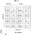
- FIG. 5 illustrates a pattern of matching a CRS and a DRS defined in a 3GPP LTE system (e.g. release-8) to a downlink RB pair.
- a downlink RB pair as a unit to which a reference signal is mapped can be represented by a product of one subframe in the time domain and 12 subcarriers in the frequency domain. That is, one RB pair has a length corresponding to 14 OFDM symbols in case of normal CP and a length corresponding to 12 OFDM symbols in case of extended CP.
- FIG. 5 shows an RB pair in case of normal CP.
- FIG. 5 shows positions of reference signals on an RB pair in a system in which an eNB supports four transmit antennas.
- REs denoted by 'R0', 'R1', 'R2' and 'R3' correspond to CRS positions for antenna port indexes 0, 1, 2 and 3.
- REs denoted by 'D' correspond to DRS positions.
- High-order multiple input multiple output (MIMO), multi-cell transmission, enhanced multi-user (MU)-MIMO, etc. are considered in LTE-A evolved from 3GPP LTE.
- DRS based data demodulation is being considered. That is, a DRS (or UE-specific reference signal or DMRS) for two or more layers can be defined to support data transmission through an additional antenna, separately from a DRS (corresponding to antenna port index 5) for rank 1 beamforming defined in 3GPP LTE (e.g. release-8).
- UE-specific reference signal ports supporting up to 8 transmit antenna ports can be defined as antenna port numbers 7 to 12 and can be transmitted in REs which do not overlap with other reference signals.
- LTE-A may separately define an RS related to feedback of channel state information (CSI) such as CQI/PMI/RI for a new antenna port as a CSI-RS.
- CSI-RS ports supporting up to 8 transmit antenna ports can be defined as antenna port numbers 15 to 22 and can be transmitted in REs which do not overlap with other reference signals.
- CoMP transmission/reception scheme (which is also referred to as co-MIMO, collaborative MIMO or network MIMO) is proposed to meet enhanced system performance requirements of 3GPP LTE-A.
- CoMP can improve the performance of a UE located at a cell edge and increase average sector throughput.
- ICI inter-cell interference
- a conventional LTE system uses a method for allowing a UE located at a cell edge in an interfered environment to have appropriate throughput using a simple passive scheme such as fractional frequency reuse (FFR) through UE-specific power control.
- FFR fractional frequency reuse
- CoMP can be applied.
- CoMP applicable to downlink can be classified into joint processing (JP) and coordinated scheduling/beamforming (CS/CB).
- JP joint processing
- CS/CB coordinated scheduling/beamforming
- each point (eNB) of a CoMP coordination unit can use data.
- the CoMP coordination unit refers to a set of eNBs used for a coordinated transmission scheme.
- the JP can be divided into joint transmission and dynamic cell selection.
- the joint transmission refers to a scheme through which PDSCHs are simultaneously transmitted from a plurality of points (some or all CoMP coordination units). That is, data can be transmitted to a single UE from a plurality of transmission points. According to joint transmission, quality of a received signal can be improved coherently or non-coherently and interference on other UEs can be actively erased.
- Dynamic cell selection refers to a scheme by which a PDSCH is transmitted from one point (in a CoMP coordination unit). That is, data is transmitted to a single UE from a single point at a specific time, other points in the coordination unit do not transmit data to the UE at the time, and the point that transmits the data to the UE can be dynamically selected.
- CoMP coordination units can collaboratively perform beamforming of data transmission to a single UE.
- user scheduling/beaming can be determined according to coordination of cells in a corresponding CoMP coordination unit although data is transmitted only from a serving cell.
- coordinated multi-point reception refers to reception of a signal transmitted according to coordination of a plurality of points geographically spaced apart from one another.
- a CoMP reception scheme applicable to uplink can be classified into joint reception (JR) and coordinated scheduling/beamforming (CS/CB).
- JR is a scheme by which a plurality of reception points receives a signal transmitted over a PUSCH
- CS/CB is a scheme by which user scheduling/beamforming is determined according to coordination of cells in a corresponding CoMP coordination unit while one point receives a PUSCH.
- a UE can receive data from multi-cell base stations collaboratively using the CoMP system.
- the base stations can simultaneously support one or more UEs using the same radio frequency resource, improving system performance.
- a base station may perform space division multiple access (SDMA) on the basis of CSI between the base station and a UE.
- SDMA space division multiple access
- a serving eNB and one or more collaborative eNBs are connected to a scheduler through a backbone network.
- the scheduler can operate by receiving channel information about a channel state between each UE and each collaborative eNB, measured by each eNB, through the backbone network.
- the scheduler can schedule information for collaborative MIMO operation for the serving eNB and one or more collaborative eNBs. That is, the scheduler can directly direct collaborative MIMO operation to each eNB.
- the CoMP system can be regarded as a virtual MIMO system using a group of a plurality of cells. Basically, a communication scheme of MIMO using multiple antennas can be applied to CoMP.
- the ACK/NACK information is control information that is fed back to a transmitter from a receiver according to whether decoding of data transmitted from the transmitter is successful. For example, when decoding of DL data of a UE is successful, the UE may feedback ACK information to an eNB and otherwise feedback NACK information to the eNB. In detail, in an LTE system, there may be three cases in which the receiver needs to transmit ACK/NACK, which will be described below.
- ACK/NACK is transmitted in response to transmission of a PDSCH indicated by detection of a PDCCH.
- ACK/NACK is transmitted in response to a PDCCH indicating release of semi-persistent scheduling (SPS).
- SPS semi-persistent scheduling
- ACK/NACK is transmitted in response to a PDSCH transmitted without detection of a PDCCH, which refers to ACK/NACK to transmission of an SPS PDSCH.
- the ACK/NACK transmission scheme is not limited to any one of the aforementioned three cases.
- the FDD scheme is a scheme of separating DL and UL for each respective independent frequency band and performing transmission and reception. Accordingly, when an eNB transmits a PDSCH in a DL band, a UE may transmit ACK/NACK response indicating whether DL data reception is successful via a PUCCH on a UL band corresponding to the DL band after a specific period of time. Accordingly, the UE may operate with DL and UL having one to one correspondence.
- control information about DL data transmission of the eNB may be transmitted to the UE through a PDCCH, and the UE that receives data, which is scheduled to the UE through the PDCCH, through a PDSCH may transmit ACK/NACK through a PUCCH as a channel for transmission of UL control information (or in a piggyback manner on a PUSCH).
- a PUCCH for transmission of ACK/NACK is not pre-allocated to each UE but instead a plurality of UEs in a cell uses a plurality of PUCCHs separated for respective points of time.
- a PUCCH resource corresponding to a PDCCH in which the UE receives scheduling information of the corresponding DL data may be used.
- a region in which a PDCCH of each DL subframe is transmitted includes a plurality of control channel elements (CCEs), and a PDCCH transmitted to one UE in a random subframe includes one or a plurality of CCEs among CCEs constituting a PDCCH region of the subframe.
- CCEs control channel elements
- a PDCCH transmitted to one UE in a random subframe includes one or a plurality of CCEs among CCEs constituting a PDCCH region of the subframe.
- resources for transmission of a plurality of PUCCHs are present.
- the UE may transmit ACK/NACK through a PUCCH with an index corresponding to an index of a specific CCE (e.g., a first or lowest CCE) among CCEs constituting a PDCCH received by the UE.
- a specific CCE e.g., a first or lowest CCE
- a UE transmits an ACK/NACK signal on PUCCH #4 corresponding to CCE #4, the first (or the lowest) CCE of the PDCCH that schedules the PDSCH.
- n-k subframe index
- n (1) PUCCH represents a resource index of PUCCH format 1 for ACK/NACK/DTX transmission
- N (1) PUCCH denotes a signaling value received from a higher layer
- n CCE denotes the smallest value of CCE indexes used for PDCCH transmission.
- a cyclic shift, an orthogonal spreading code and a physical resource block (PRB) for PUCCH formats 1a/1b are obtained from n (1) PUCCH .
- D is a DL subframe
- U is a UL subframe
- S is a special subframe.
- the special subframe denoted by S may include three fields, i.e., downlink pilot timeslot (DwPTS), guard period (GP), and uplink pilot timeslot (UpPTS).
- DwPTS is a time period reserved for DL transmission
- UpPTS is a time period reserved for UL transmission.
- a UE may transmit ACK/NACK information as a response to PDSCH transmission in one or more DL subframe in one UL subframe.
- the UE may transmit HACK ACK/NACK information in a UL subframe n as a response to transmission of PDSCH received in a DL subframe (n-k).
- k may be given according to the UL-DL configuration.
- k may be given as a DL related set index K: ⁇ k 0 , k, 1 ..., k M-1 ⁇ according to the UL-DL of Table 3 as shown in Table 4 below.
- ACK/NACK information about data received in a DL subframe 5 may be transmitted in the UL subframe 9.
- a method of determining a PUCCH resource index for transmission of ACK/NACK in a TDD system will be described in detail.
- the number of elements ⁇ k 0 , k, 1 ..., k M-1 ⁇ of a set K is referred to as M.
- M the number of elements of the set K for a subframe 2
- the number of elements of the set K for the subframe 2 is 4.
- the UE may determine a PUCCH resource n (1) PUCCH for HARQ ACK/NACK transmission in a subframe n as follows.
- n PUCCH 1 M ⁇ m ⁇ 1 ⁇ N p + m ⁇ N p + 1 + n CCE + N PUCCH 1
- n (1) PUCCH is a resource index of PUCCH format 1 for transmission of ACK/NACK
- N (1) PUCCH is a signaling value transmitted from a higher layer
- n CCE is a smallest value among CCE indexes used for PDCCH transmission in a subframe (n-k m ) (here, k m is a smallest value in a set K).
- N p may be determined according to Equation 3 below.
- N p max 0, ⁇ N RB DL ⁇ N sc RB ⁇ p ⁇ 4 / 36 ⁇
- N RB DL refers to DL bandwidth configuration and is represented in a unit of N sc RB .
- N sc RB is a size of a resource block in the frequency domain and is represented by the number of subcarriers.
- n (1) PUCCH may be determined according to higher layer configuration.
- the UE may determine a PUCCH resource for HARQ ACK/NACK transmission as follows.
- n (1) PUCCH, i (0 ⁇ i ⁇ M -1) is referred to as an ACK/NACK resource derived from a subframe (n-k i ) and HARQ-ACK(i) is referred to as ACK/NACK response from a subframe (n-k i ).
- an ACK/NACK resource n (1) PUCCH, i may be determined according to Equation 4 below.
- n PUCCH , i 1 M ⁇ i ⁇ 1 ⁇ N p + i ⁇ N p + 1 + n CCE,i + N PUCCH 1
- N (1) PUCCH is a signaling value transmitted from a higher layer.
- n CCE, i is a smallest value among CCE indexes used for PDCCH transmission in a subframe (n-k i ).
- p is selected from ⁇ 0, 1, 2, 3 ⁇ to satisfy N p ⁇ n CCE,i ⁇ N p+1 .
- Np may be determined according to Equation 3 above.
- n (1) P UCCH, i may be determined according to higher layer configuration.
- the UE transmits bits b(0), b(1) on an ACK/NACK resource n (1) PUCCH in a subframe n using PUCCH format 1b.
- the UE may not transmit ACK/NACK response in a subframe n.
- HARQ-ACK(i) indicates the HARQ ACK/NACK/DTX result of an i-th data unit (0 ⁇ i ⁇ 3).
- Discontinuous transmission (DTX) represents that there is no transmission of a data unit corresponding to HARQ-ACK(i) or the UE does not detect the data unit corresponding to HARQ-ACK(i).
- HARQ-ACK is interchangeably used.
- Maximum 4 PUCCH resources i.e., n (1) PUCCH,0 to n (1) PUCCH,3 ) can be occupied for each data unit.
- the multiplexed ACK/NACK signal is transmitted through one PUCCH resource selected from the occupied PUCCH resources.
- n (1) PUCCH,X represents a PUCCH resource actually used for ACK/NACK transmission
- b(0)b(1) indicates two bits transmitted through the selected PUCCH resource, which are modulated using QPSK.
- the UE transits bits (1, 1) to a BS through a PUCCH resource linked with n (1) PUCCH,1 . Since combinations of PUCCH resources and QPSK symbols cannot represent all available ACK/NACK suppositions, NACK and DTX are coupled except some cases (NACK/DTX, N/D).
- the present invention proposes a method using a scrambling sequence parameter and/or a plurality of antenna ports associated with an enhanced control channel (e.g., an E-PDCCH).
- an enhanced control channel e.g., an E-PDCCH
- the UE may detect a control channel containing information (or DL scheduling information) about DL assignment and receive a PDSCH corresponding to the control channel.
- the UE may feedback information about whether PDSCH reception is successful after a predetermined period of time.
- a resource to be used for ACK/NACK transmission may be determined from a PDCCH in which the DL assignment is transmitted.
- the UE may recognize a first index (e.g., an index n) from CCEs of a PDCCH used for transmission of DL assignment and transmit ACK/NACK using a PUCCH resource corresponding to N offset PUCCH + n obtained by adding the CCE index to N offset PUCCH as offset indicating beginning of a PUCCH resource region used for ACK/NACK.
- N offset PUCCH may be a value signaled by a higher layer like N (1) PUCCH of Equation 1 above.
- the method of determining a PUCCH resource based on a CCE index of a PDCCH can be applied to the legacy-PDCCH in which one CCE is used for only one UE without any problem, but it can be difficult to apply the method to an enhanced PDCCH (i.e., an E-PDCCH).
- the E-PDCCH can be demodulated based on a UE-specific RS (or DMRS) and can apply MU-MIMO. Accordingly, when a PUCCH resource is determined using a conventional method, ACK/NACK resource collision may occur.
- two or more UEs can receive DL assignment divided according to precoding (or UE-specific RS (or DMRS)) while sharing the same time/frequency resource (i.e., CCE or ECCE, and hereinafter, referred to as (E)CCE).
- precoding or UE-specific RS (or DMRS)
- DMRS UE-specific RS
- E ECCE
- a plurality of UEs i.e., UEs belonging to one E-PDCCH MU-MIMO group
- the same (E)CCE can simultaneously transmit ACK/NACK signals using the same PUCCH resource (i.e., ACK/NACK resource collision).
- a plurality of PUCCH resources for one DL assignment is reserved as ACK/NACK resources, and an individual UE selects some of the plural reserved PUCCH resources and performs ACK/NACK feedback.
- a UE may select one of the L PUCCH resources linked with the L (E)CCEs and feedback ACK/NACK.
- a value of the parameter k may be indicated using a specific field in DL assignment or selected from the feature of an RS (UE-specific RS or DMRS) used for detection (or demodulation) of DL assignment.
- RS UE-specific RS or DMRS
- a PUCCH resource linked with (E)CCE having an index corresponding to k can be selected.
- a PUCCH resource linked with (E)CCE n k may be selected.
- k is an (E)CCE index number
- p is an antenna port number
- L is an aggregation level.
- mod refers to modulo calculation and X mod Y refers to a remainder obtained by dividing X by Y.
- L 2
- a PUCCH resource linked with (E)CCE n 0 may be selected
- an antenna port number 8 or 10 or antenna port number 108 or 110
- a PUCCH resource linked with (E)CCE n1 may be selected.
- An (E)CCE index may be selected using a scramble sequence initialization value of a UE-specific RS (or DMRS) used for demodulation of a PDCCH for carrying DL assignment and an ACK/NACK resource linked with the selected (E)CCE index.
- the scramble sequence initialization value may be referred to as a scrambling identifier (SCID).
- a resource to be used as ACK/NACK feedback may be determined.
- an eNB in order to determine PUCCH that does not collide with each UE that belongs to the same E-PDCCH MU-MIMO group, an eNB needs to be appropriately configure an E-PDCCH aggregation level, an (E)CCE index number, an antenna port of an RS (UE-specific RS or DMRS), and/or a scrambling sequence and to transmit an E-PDCCH for each UE.
- the above proposed operation can be smoothly performed when one DL assignment has a plurality of (E)CCEs, the operation may be limited to only a case of two or more aggregation levels. This means that two or more aggregation levels need to be used in order to transmit DL assignment using MU-MIMO by an eNB.
- the UE may determine a specific (E)CCE index n* (e.g., (E)CCE n 0 with a lowest index or (E)CCE index derived from a UE ID, etc.) among the L (E)CCEs, select a PUCCH resource (e.g., n * + k + N offset PUCCH ) linked with an (E)CCE index n*+k obtained by applying predetermined offset (e.g., k) to the specific (E)CCE index (which means an index corresponding to a representative AP of an E-PDCCH according to one-to-one correspondence), and feedback ACK/NACK.
- a specific (E)CCE index n* e.g., (E)CCE n 0 with a lowest index or (E)CCE index derived from a UE ID, etc.
- a parameter k corresponding to offset may be indicated using a specific field of a DCI format of DL assignment like in the aforementioned example or determined by a scramble sequence initialization value (e.g., SCID) and/or an antenna port of an RS used for demodulation of DL assignment.
- a DCI format of DL assignment may refer to, for example, a DCI format 1A, 1B, ID, 1, 2A, 2, 2B, 2C, 2D, etc.
- This method may be useful for transmission of MU-MIMO E-PDCCH particularly when an aggregation level is 1 (i.e., when only one (E)CCE is used).
- a parameter k corresponding to an index of a PUCCH region may be indicated using a specific field of a DCI format of DL assignment like in the aforementioned example or determined by a scramble sequence initialization value (e.g., SCID) and/or an antenna port of an RS used for demodulation of DL assignment.
- SCID scramble sequence initialization value
- a plurality of PUCCH resources may be linked with one (E)CCE.
- the UE may determine a specific (E)CCE index n* (e.g., (E)CCE n 0 with a lowest index or an (E)CCE index derived from a UE ID, etc.) associated with transmission of DL assignment, select an appropriate k, and use a PUCCH resource N offset PUCCH + Kn* + k.
- n* e.g., (E)CCE n 0 with a lowest index or an (E)CCE index derived from a UE ID, etc.
- a parameter k associated with determination of a PUCCH resource index may be indicated using a specific field of a DCI format of assignment like in the aforementioned example or may be determined by a scramble sequence initialization value (e.g., SCID) and/or an antenna port of an RS used for demodulation of DL assignment.
- SCID scramble sequence initialization value
- a PUCCH resource region may be classified (divided) into a region used when a legacy-PDCCH receives DL assignment and a region used when an E-PDCCH receives DL assignment.
- the classification (or division) is effective to prevent ACK/NACK resource collision of a legacy-PDCCH and a PDSCH scheduled by an E-PDCCH.
- an eNB needs to divide an offset value N offset PUCCH indicating a start point of each PUCCH resource region into values for the legacy-PDCCH and the E-PDCCH and to indicate the values.
- the methods according to the present invention can be restrictedly applied to a specific E-PDCCH search space (e.g., a UE-specific search space). This is because DCI that is simultaneously received by many UEs is generally transmitted in a common search space, and thus, the necessity of using MU-MIMO is low.
- a specific E-PDCCH search space e.g., a UE-specific search space.
- an E-PDCCH may be divided into a plurality of REGs, and an interleaved E-PDCCH transmission mode (e.g., a distributed type E-PDCCH transmission) for interleaving the REGs can be defined, or a non-interleaved E-PDCCH transmission mode (e.g., localized type E-PDCCH transmission) in which one E-PDCCH (E)CCE is transmitted only in one frequency domain unit (e.g., a PRB pair) or one space domain unit can be defined.
- an interleaved E-PDCCH transmission mode e.g., a distributed type E-PDCCH transmission
- a non-interleaved E-PDCCH transmission mode e.g., localized type E-PDCCH transmission
- one E-PDCCH (E)CCE is transmitted only in one frequency domain unit (e.g., a PRB pair) or one space domain unit can be defined.
- the aforementioned method of determining a PUCCH resource using the scrambling sequence parameter and/or the antenna port associated with the E-PDCCH may not be applied in the interleaved E-PDCCH transmission mode in which it is difficult to apply MU-MIMO and may be applied only to a non-interleaving transmission mode in which application of MU-MIMO is appropriate.
- the methods according to the present invention can be restrictedly applied to a specific aggregation level.
- an E-PDCCH using many (E)CCEs like in the case of an aggregation level 4 or 8 is generally used when a channel status is poor, and thus, it may not be appropriate to apply MU-MIMO.
- the aforementioned method of determining a PUCCH resource using the scrambling sequence parameter and/or the antenna port associated with the E-PDCCH may restrictedly applied to a low aggregation level such as an aggregation level 1 or 2.
- the eNB may notify the UE of how an ACK/NACK feedback resource is used for each respective search space or subframe via a higher layer signal such as an RRC.
- the eNB may notify the UE of information about the number of the PUCCH resource regions or information about the number of the PUCCH resources linked with one (E)CCE via a higher layer signal such as a RRC.
- separate PUCCH resources other than a PUCCH resource linked with (E)CCE may be reserved using a higher layer signal such as an RRC, and an appropriate resource may be selected among separate PUCCH resources.
- a UE that decodes DL assignment may recognize one PUCCH resource linked with (E)CCE, also recognize some PUCCH resources pre-transmitted via an RRC, and then determine a final PUCCH resource to be used for ACK/NACK transmission via appropriate indication.
- indication for determination of a resource used for actual transmission among the PUCCH resources recognized by the UE may be determined using a specific field in DL assignment or determined from a scramble sequence initialization value (e.g., SCID) and/or an antenna port of an RS used for detection (or demodulation) of DL assignment.
- SCID scramble sequence initialization value
- the UE recognizes one PUCCH resource (e.g., a PUCCH resource n 1 ) linked with (E)CCE used for transmission of DL assignment and recognizes three PUCCH resources (e.g., PUCCH resources n 2 , n 3 , and n 4 ) pre-configured via an RRC.
- one PUCCH resource e.g., a PUCCH resource n 1
- (E)CCE used for transmission of DL assignment
- three PUCCH resources e.g., PUCCH resources n 2 , n 3 , and n 4
- an RS associated with an E-PDCCH is one of antenna port numbers 7, 8, 9, and 10 (or 107, 108, 109, and 110), one of the PUCCH resources n1, n2, n3, and n4 may be determined.
- a PUCCH resource may also be appropriately determined in order to prevent PUCCH resource collision according to the aforementioned principle of the present invention.
- a first PUCCH resource may be determined as n* and a second PUCCH resource may be determined as n*+1 according to the aforementioned method.
- the UE detects (or demodulates) an E-PDCCH using one antenna port of an RS and a plurality of PUCCH resources to be used for transmit diversity may be indicted by one antenna port.
- the UE may determine a PUCCH resource using one representative antenna port (or a virtual antenna port).
- the representative antenna port may be determined as an antenna port with a minimum index among the used antenna ports or determined as the antenna port used to detect a representative (E)CCE (e.g., (E)CCE with a minimum index).
- a UE may select M resources among the L PUCCH resources linked with the L (E)CCEs and feedback ACK/NACK.
- a PUCCH resource linked with two (E)CCEs n k and n (k+1) may be selected.
- the UE may select PUCCH resources n 0 and n 1 , and if the antenna port is 8 or 10 (or if the antenna port is 108 or 110), the UE may select PUCCH resources n 2 and n 3 .
- k may be determined based on an antenna port number.
- k may be determined based on a scramble sequence initialization value (e.g., SCID) of an RS associated with an E-PDCCH.
- SCID scramble sequence initialization value
- K that is the number of PUCCH resource regions may be associated with an ACK/NACK transmission method in a PUCCH.
- a plurality of PUCCH resources may be linked with one (E)CCE.
- the UE may determine a specific (E)CCE index n* (e.g., (E)CCE n 0 with a lowest index or (E)CCE index derived from a UE ID, etc.) associated with transmission of DL assignment and use M PUCCH resources N offset PUCCH +Kn*+k, N offset PUCCH + Kn * + k + 1, ... , N offset PUCCH + Kn * + k + M ⁇ 1.
- n* e.g., (E)CCE n 0 with a lowest index or (E)CCE index derived from a UE ID, etc.
- the number of UEs that simultaneously belong to one MU-MIMO group in one E-PDCCH resource may be limited.
- a single E-PDCCH resource includes four (E)CCEs and one PUCCH resource is linked with each respective (E)CCE, or a single E-PDCCH resource includes two (E)CCEs and two PUCCH resources are linked with each (E)CCE.
- the present invention may be limited to a case in which MU-MIMO is performed on up to two UEs that perform transmit diversity using two PUCCH resources.
- PUCCH resources m 0 and m 1 may be used, and when an antenna port 8 (or 108) is used in relation to an E-PDCCH, PUCCH resources m 2 and m 3 may be used.
- MU-MIMO may be performed on up to four UEs to which PUCCH transmit diversity is applied. In this case, each UE may occupy one PUCCH resource.
- a UE to which PUCCH transmission diversity is not applied may use PUCCH resources m 0 , m 2 , m 1 , and m 3 , respectively when the UE uses antenna ports 7, 8, 9, and 10 (or 107, 108, 109, and 110) in relation to an E-PDCCH.
- one E-PDCCH when one E-PDCCH is transmitted using a plurality of resource regions (e.g., (E)CCE), different antenna ports may be mapped to respective resource regions.
- one representative antenna port may be determined and the E-PDCCH related operation may be performed based on the representative antenna port.
- the representative antenna port may be determined according to any one of the following methods.
- the representative antenna port may be determined to have a minimum index among antenna port(s) mapped to an E-PDCCH resource region. For example, when an antenna port 7 (or 107) is mapped in a resource region 1 and an antenna port 8 (or 108) is mapped in a resource region 2, the representative antenna port may be determined as the antenna port 7 (or 107) with respect to an E-PDCCH using both the two resource regions.
- the representative antenna port may be determined to have a maximum index among antenna port(s) mapped to an E-PDCCH resource region. For example, when an antenna port 7 (or 107) is mapped in a resource region 1 and an antenna port 8 (or 108) is mapped in a resource region 2, the representative antenna port may be determined as the antenna port 8 (or 108) with respect to an E-PDCCH using both the two resource regions.
- the method 2 may be useful to prevent collision between an RS antenna port of an E-PDCCH of a cell and an RS antenna port of a PDSCH of an adjacent cell.
- an RS that uses a PDSCH of an adjacent cell uses antenna ports, the number of which corresponds to the number of ranks from the antenna port 7 as a start antenna port, according to ranks of the antenna ports, and thus, an antenna port with a low index is used more frequently.
- the method 2 when the representative antenna port of the E-PDCCH is determined, since an antenna port with a high index is more frequently used as the representative antenna port of the E-PDCCH, a collisional frequency with the antenna port of the PDSCH of the adjacent cell can be reduced.
- the method 2 is particularly effective to E-PDCCH demodulation using the representative antenna port, which will be described below.
- Method 3 Priority for selection of the representative antenna port may be pre-transmitted to the UE via a higher layer signal such as an RRC, and one of E-PDCCH related antenna port(s) may be selected according to the priority.
- the eNB may determine priorities for antenna ports 7, 8, 9, and 10 (or antenna ports 107, 108, 109, and 110) and determine an antenna port with highest priority as the representative antenna port among a plurality of antenna ports when the plural antenna ports are mapped to one E-PDCCH.
- the method 3 is advantageous in that the eNB can adjust a method of determining a representative antenna port such that representative antenna ports between cells do not overlap with each other (i.e., different representative antenna ports are different).
- Method 4 - A method of determining a representative antenna port may be determined based on an (E)CCE index, an antenna port (AP) index, a UE ID, a cell ID, etc.
- a hash function may be predefined based on parameters such as an (E)CCE index, an AP index, a UE ID, a cell ID, etc.
- a hash function value i.e., a result value of the hash function
- different UEs may use different representative antenna ports to prevent RS collision and use a PUCCH region divided for the respective representative antenna ports without collision.
- An antenna port used to detect a representative resource region may be determined as a representative antenna port among resource region(s) of the E-PDCCH.
- the representative resource region may be a resource region with a minimum or maximum index among resources regions used for the E-PDCCH.
- the representative resource region may be determined as a resource region with a minimum resource region index.
- the minimum resource region index may be a minimum value among indexes present when the resource regions included in the corresponding E-PDCCH are determined (i.e., during an aggregation procedure), but not a minimum value of indexes that are finally determined for resource regions included in the corresponding E-PDCCH. That is, a resource region in which aggregation begins may be determined as the representative antenna port.
- the resource region n that is a resource region in which aggregation of regions of the corresponding E-PDCCH begins (i.e., a resource region with a minimum index during an aggregation procedure) may be a representative resource region.
- a final index that is actually occupied by each of the aggregated resource regions may be different from an index of a resource region during the aggregation procedure, and thus, the minimum index and the final index needs to be differentiated during the aggregation procedure.
- k i.e., n, n+1, n+2, ..., n+k-1
- resource regions n+1, n+2, ..., n+k-1 may be present on a different PRB from a PRB pair in which the resource region n is present.
- resource regions n, n+1-P, n+2-P, ..., n+k-1-P may be aggregated to constitute one E-PDCCH.
- the resource region n may be determined as a resource region with a minimum index from a viewpoint of the aggregation procedure, and accordingly, the resource region n may be determined as the representative resource region.
- resource regions 0, 1, and 2 may be defined in a 0 th PRB pair
- resource regions 3, 4, and 5 may be defined in a first PRB pair
- resource regions 6, 7, and 8 may be defined in a second PRB pair.
- a resource region index Pt+X may be substituted with an index as a result obtained by performing calculation Pt+(X mod P) in order to prevent two resource regions from being positioned in different PRB pairs.
- a resource region Pt+P may be substituted with Pt as a result of Pt+(P mod P). That is, resources regions Pt+P-1 and Pt that belong to the same PRB may be aggregated.
- the resource region Pt+P-1 with a minimum original index may be a representative resource region among aggregated resource regions. Overview of calculation of a final resource region index will now be described.
- An antenna port used to detect a representative resource region may be determined as a representative antenna port, and in this regard, when information about the representative resource region may be pre-transmitted via a higher layer signal such as an RRC or priorities between resource regions may be predetermined and a plurality of resource regions is used, a resource region with highest priority may be determined as the representative resource region.
- a resource region with highest priority may be determined as the representative resource region.
- priority may be determined according to a candidate with a lower aggregation level is configured in each resource region.
- one E-PDCCH and resource regions 1 and 2 are aggregated and are transmitted with an aggregation level 2, since a candidate of an aggregation level 1 using the resource region 1 is present, the UE attempts to detect an E-PDCCH in a corresponding resource region.
- the candidate of the aggregation level 1 is not present in the resource region 2, if the UE does not attempts to detect the E-PDCCH, the resource region 1 may be determined as the representative resource region in order to reuse channel estimation.
- different scrambling sequence parameters e.g., SCIDs
- SCIDs may be mapped to respective resource regions
- a representative SCID parameter may be determined based on an index of the SCID using the methods 1 to 3
- the representative resource region may be determined based on the index of the resource region and the SCID mapped to the representative resource region may be determined as a representative SCID parameter.
- one representative antenna port may be used to map an E-PDCCH to a resource element.
- an antenna port of an RS to be used for demodulation of the E-PDCCH may be determined as the representative antenna port.
- the representative antenna port may be determined using one or more methods among the methods 1 to 7. This method may be effective to a case in which a plurality of resource regions used for one E-PDCCH is positioned in one PRB pair or in adjacent PRB pairs. This is because a channel status is maintained in one PRB pair or adjacent PRB pairs, and thus, individual resource regions cannot be channel-estimated using a separate RS and one channel estimation can be performed using an RS of one representative antenna port. Accordingly, transmission power of an RS that is not an RS of a representative antenna port, may be allocated to an RS of the representative antenna port to enable power boosting, thereby achieving more accurate channel estimation.
- FIGs. 6 and 7 are diagrams for explanation of an operation of demodulating an E-PDCCH transmitted through a plurality of resource regions using a representative antenna port according to an embodiment of the present invention.
- FIG. 6 illustrates a case of one PRB pair and
- FIG. 7 illustrates a case of adjacent PRB pairs.
- FIG. 6 illustrates the example in which an eNB uses (aggregates) (E)CCE 0 and (E)CCE 2 and transmits a single E-PDCCH to a UE.
- the UE may determine a representative antenna port of two resource regions (i.e., (E)CCEs 0 and 2) according to one or more methods of the aforementioned methods.
- AP 9 or AP 109 is selected as the representative antenna port.
- a channel can be estimated using an RS (UE-specific RS or DMRS) corresponding to the representative antenna port in the two (E)CCEs, and E-PDCCH demodulation can be used based on the estimated channel.
- RS UE-specific RS or DMRS
- FIG. 7 illustrates the example in which two resource regions (i.e., (E)CCEs 0 and 6) positioned in adjacent PRB pairs are aggregated and one E-PDCCH is transmitted.
- the UE may estimate an RS corresponding to the representative antenna port and perform E-PDCCH demodulation based on the estimated channel.
- One or more of the methods 1 to 9 of determination of a representative antenna port may be complexly used.
- the representative antenna port may be determined as an antenna port used to detect the representative resource region (e.g., a resource region with a minimum index).
- the used method is advantageous in that the method can be used together with various operations for defining a representative resource region associated with resource regions, for example, an operation for selecting an ACK/NACK resource connected to a resource region.
- the method is advantageous in that antenna ports between cells do not overlap each other to prevent interference between RSs when priority for determining the representative antenna port is determined via a higher layer signal such as an RRC, etc.
- the representative antenna port may be determined as an antenna port allocated to a representative resource region with a minimum index.
- an index of each resource region may be determined via a higher layer signal such as an RRC, etc.
- FIG. 8 is a diagram for explanation of an operation of demodulating an E-PDCCH transmitted through a plurality of resource regions using a representative antenna port according to another embodiment of the present invention.
- FIG. 8 illustrates the example in which two adjacent cells allocate antenna ports to resource regions (e.g., (E)CCE) present in the same PRB pair using the same method and denotes resource region indexes (e.g., (E)CCE indexes) using different methods. Accordingly, even if all resource regions of the corresponding PRB pair are aggregated, representative resource regions (e.g., resource region with a minimum index in each cell) and representative antenna ports mapped to the respective representative resource regions may be determined not to overlap (or to be different) between cells.
- resource regions e.g., (E)CCE
- a cell 1 and a cell 2 denote indexes for resource regions using different methods, even if the indexes (i.e., lowest index) of representative resource regions are the same value, 0, positions of physical resource regions that are actually indicated by the respective resource region indexes may be differently determined, and thus, different representative resource regions may be determined for the respective cells. Accordingly, antenna ports (i.e., representative antenna ports) mapped to the determined representative resource regions may also be differently determined.
- a UE that belongs to the cell 1 may determine a resource region (a first resource region from a viewpoint of a physical resource position) corresponding to a resource region index 0 as a representative resource region, determine an antenna port (i.e., AP 7) corresponding to the determined representative resource region as a representative antenna port, and demodulate all resource regions (resource region indexes 0 to 3) of one E-PDCCH using an RS corresponding to the representative antenna port.
- a resource region a first resource region from a viewpoint of a physical resource position
- an antenna port i.e., AP 7
- a UE that belong to the cell 2 may determine a resource region (a third resource region from a viewpoint of a physical resource position) corresponding to a resource region index 0 as representative resource region, determine an antenna port (i.e., AP 9) corresponding to the determined representative resource region as the representative antenna port, and demodulate all resource regions (resource region indexes 0 to 3) of one E-PDCCH using an RS corresponding to the representative antenna port.
- a resource region a third resource region from a viewpoint of a physical resource position
- an index for each resource region may be denoted directly via a higher layer signal such as an RRC or derived from parameters such as a cell ID, a UE ID, etc. according to a predetermined rule.
- the eNB may transmit a specific seed value to the UE via direct signaling or indirect signaling derived from other parameters.
- the UE may denote predetermined offset to an index of an E-PDCCH resource region (e.g., (E)CCE) based on the corresponding seed value transmitted from the eNB or correct (e.g., permutation, cyclic shift, or interleaving) a position of a resource region index to a pattern determined according to the corresponding seed value.
- E-PDCCH resource region e.g., (E)CCE
- correct e.g., permutation, cyclic shift, or interleaving
- a specific cell may transmit information about a method of denoting a resource region index by the cell and information about a standard (e.g., priority for each antenna port applied for determination of a representative antenna port, information about an antenna port allocated to each resource region, etc.) applied for determination of an antenna port to adjacent cells via backhaul, etc.
- a standard e.g., priority for each antenna port applied for determination of a representative antenna port, information about an antenna port allocated to each resource region, etc.
- the aforementioned operation of determining the representative resource region and/or the operation of determining the representative antenna port can be applied to all E-PDCCH PRB pairs, can be applied in units of separate PRB pairs, or can be applied in units of PRB pair groups (e.g., a set of a predetermined number of adjacent PRB pairs).
- one representative antenna port may be selected from a PRB pair or a PRB pair group, and resource regions that belong to the same PRB pair or PRB pair group may be attempted to be detected as a corresponding representative antenna port among resource regions aggregated with a specific E-PDCCH (or demodulation of an E-PDCCH may be attempted using an RS corresponding to the corresponding representative antenna port).
- an aggregation level of an E-PDCCH is L
- the L (E)CCEs may be represented by #n CCE , #n CCE +1, #n CCE +2, ..., #n CCE +L-1 (or #n ECCE , #n ECCE +1, #n ECCE +2, ..., #n ECCE +L-1).
- An index of an antenna port (AP) allocated (or mapped) to each (E)CCE may be determined as follows.
- Example 1 - Four (E)CCEs may be formed in one PRB pair, and APs #p, #p+1, #p+2, and #p+3 may be sequentially allocated in an order of the (E)CCEs.
- the example can be applied to a case in which four or more APs are defined like a normal CP subframe and the number of REs that can be used as an E-PDCCH is also sufficient.
- Example 2 - Two (E)CCEs may be formed in one PRB pair, and APs #p and #p+2 may be sequentially allocated in an order of the (E)CCEs.
- the example can be applied to a case in which four or more APs are defined like a normal CP subframe but the number of REs that can be used as an E-PDCCH is not sufficient and thus only two (E)CCEs are formed in one PRB pair.
- DMRSs i.e., DMRS ports #p and #p+2
- the DMRSs may be transmitted to be independently consumed in different REs.
- DMRS ports 7 and 8 (or 107 and 108) may be multiplexed and transmitted using a CDM method via different orthogonal cover codes in the same RE
- DMRS ports 9 and 10 (or 109 and 110) may be multiplexed and transmitted using a CDM method via different orthogonal cover codes in other the same RE.
- Example 3 - Two (E)CCEs may be formed in one PRB pair, and APs #p and #p+1 may be sequentially allocated in an order of the (E)CCEs.
- the example can be applied to a case in which only two APs are defined like an extended CP subframe.
- a representative AP index for the E-PDCCH may be determined according to a function (e.g., a hash function) of Equation 5 below.
- a representative AP index may be determined according to a function of Equation 6 below. Equation 6 below may be defined to limit selection of one of d AP indexes as a representative AP index when an aggregation level of an E-PDCCH exceeds the number of (E)CCEs formed on one PRB pair, d.
- p refers to a minimum value (i.e., 7 or 107) of a DMRS port index (a port index 7, 8, 9, or 10, or a port index 107, 108 109, or 110) used by an E-PDCCH.
- n CCE or n ECCE refers to a lowest value among indexes of (E)CCE used for E-PDCCH transmission (e.g., which may be represented by n CCE,low or n ECCE,low ).
- D refers to the number of (E)CCEs formed on one PRB pair (e.g., which may be represented by N RB CCE or N RB ECCE ).
- L is an aggregation level, L refers to the number of (E)CCEs used in one E-PDCCH (e.g., which may be represented by N CCE EPDCCH or N ECCE EPDCCH ).
- min(a,b) refers to a minimum value of a and b.
- Z has a value 1 or 2.
- Equations 7 and 8 below may be given in the same meaning as the method of determining a representative AP according to Equation 6 above.
- Example 2 (Z 2)
- n' may correspond to a parameter for determination of an index of a resource region (e.g., (E)CCE) of an E-PDCCH, which is derived from a predetermined parameter X (e.g., an identifier of a UE).
- X e.g., an identifier of a UE.
- n' may refer to a parameter for determination of a representative resource region (or a representative (E)CCE) index) of the E-PDCCH. That is, Equation 7 and Table 8 above show that the representative AP corresponds (or is mapped) to a representative (E)CCE.
- the number of resources e.g., OFDM symbols or resource elements
- the parameter X may be a value (i.e., the parameter X is a value derived from a UE ID) for determination of a representative AP by a UE ID.
- n RNTI X may be given as a function value Y k used for determination of a search space of a PDCCH in a 3GPP LTE system.
- Y k may be determined by a UE ID (e.g., n RNTI ) according to Equation 8 below.
- Y k A ⁇ Y k ⁇ 1 mod D
- Y ⁇ 1 n RNTI ⁇ 0
- Equation 8 above k refers to a subframe index.
- an aggregation level is 1, one E-PDCCH constitutes one (E)CCE, and thus, an AP mapped to corresponding one (E)CCE is a representative AP.
- one (E)CCE present between a first (E)CCE and a last (E)CCE may be determined according to X, and an AP allocated (or mapped) to the one determined (E)CCE may be determined as a representative AP.
- X may be determined as a value derived from a parameter such as a UE ID, etc.
- an eNB may directly indicate a value to be used as X via a higher layer signal.
- E-PDCCH As described above, while a representative (E)CCE (or a representative AP) used for detection of an E-PDCCH (or demodulation of an E-PDCCH) is selected, a plurality of E-PDCCH sets may be set for a UE.
- E E-PDCCH
- the eNB may configure two E-PDCCH sets (i.e., E-PDCCH set1 and E-PDCCH set2) for one UE and may appropriately distribute an E-PDCCH candidate monitored by the corresponding UE to the two E-PDCCH sets.
- the two E-PDCCH sets may or may not overlap each other in a PRB region, and parameters such as DMRS scrambling sequences, the number of used PRBs, or the like may be differently set.
- a method of configuring a representative (E)CCE may be differently determined for each respective E-PDCCH set. For example, when a representative AP is determined according to a function according to Equation 5 or 6 above, the parameter X used for determination of an AP index may be differently determined in the plural E-PDCCH sets.
- a parameter X (i.e., E-PDCCH set-specific) given for each respective E-PDCCH set may be derived from Y k according to Equation 8 above.
- a parameter X 1 for E-PDCCH set1 is given as Y k .
- a parameter X 2 for E-PDCCH set2 may be determined in the form of a value obtained by adding a predetermined number to X 1 .
- a relationship between X 1 and X 2 may be defined according to Equation 9 below.
- X 2 X 1 + G ⁇ M L ,1
- Equation 9 above G is an integer that is equal to or greater than 1, and M L,1 is the number of E-PDCCH candidates of an aggregation level L present in E-PDCCH set1.
- a start (E)CCE index of a search space is used as a reference for selection of a representative AP in each E-PDCCH set.
- both X 1 and X 2 for E-PDCCHs set1 and set2 are determined according to Equation 8 above.
- parameters A and/or D of Equation 8 may be differently set for X 1 and X 2 such that different X 1 and X 2 may be derived from the same UE ID (e.g., n RNTI ).
- one UE may select a representative (E)CCE (or a representative AP) using different references for different E-PDCCH sets and perform E-PDCCH detection (or demodulation) using an RS corresponding to the selected representative AP.
- a PUCCH resource linked with the selected/determined representative AP may be used for ACK/NACK feedback.
- the representative AP is determined according to Equation 5 or 6 above
- the representative (E)CCE is determined and an AP corresponding (or mapped) to the determined representative (E)CCE is determined as a representative AP. That is, the representative (E)CCE may correspond to a portion (i.e., n' of Equation 7) obtained by excluding p from Equation 5 or 6 above.
- n' and a representative (E)CCE index n* may be determined according to a one-to-one mapping relationship.
- a PUCCH linked with the representative (E)CCE may be used for ACK/NACK feedback.
- a PUCCH resource e.g., n*+k+ N offset PUCCH
- predetermined offset e.g., k
- N offset PUCCH may be an offset value indicating a start point of a PUCCH resource region and provided via higher layer signaling such as an RRC, etc.
- an index of a first PUCCH resource may be determined as n * + k + N offset PUCCH and an index of a second PUCCH resource may be determined as n * + k + N offset PUCCH + 1.
- FIGs. 9 and 10 are flowcharts for explanation of an E-PDCCH-based operation method according to embodiments of the present invention.
- FIG. 9 relates to a method of determining an E-PDCCH representative AP and performing E-PDCCH transmission and reception according to the determined E-PDCCH representative AP.
- an eNB may determine a resource region to which an E-PDCCH is mapped for E-PDCCH transmission to a specific UE.
- the eNB may determine a representative AP index corresponding (or mapped) to a representative (E)CCE index among resource regions to which an E-PDCCH is mapped.
- a method of determining the representative (E)CCE and/or the representative AP may be based on the aforementioned examples of the present invention.
- the representative AP may be determined to correspond to a representative (E)CCE (e.g., n' of Equation 7 above) determined based on an identifier of the UE.
- the eNB may map an E-PDCCH to a resource element and transmit the E-PDCCH to the specific UE.
- the UE may determine a representative (E)CCE from information about a resource region in which the E-PDCCH is transmitted and determine a representative AP corresponding to the representative (E)CCE for E-PDCCH monitoring (i.e., decoding attempt).
- a method of determining the representative (E)CCE and/or the representative AP may be based on the aforementioned examples of the present invention.
- the representative AP may be determined to correspond to the representative (E)CCE (e.g., n' in Equation 7 above) determined based on an identifier of the UE.
- the UE may perform E-PDCCH demodulation using the representative AP.
- the UE may perform E-PDCCH demodulation using a channel estimated based on a DMRS corresponding to the representative AP.
- the example of FIG. 10 relates to a method of determining a PUCCH resource when the UE feedbacks ACK/NACK information to transmission of a PDSCH indicated by an E-PDCCH to the eNB.
- Steps S1011 and S1012 of FIG. 10 correspond to steps S911 and S912 of FIG. 9
- steps S1021 and S1022 of FIG. 10 correspond to steps S921 and S922 of FIG. 9 .
- repeated descriptions are not given here.
- the eNB may transmit DL data through a PDSCH scheduled according to DL assignment DCI transmitted through the E-PDCCH to the UE.
- the UE may decode the PDSCH and generate ACK/NACK information according to whether decoding is successful.
- the UE may determine a PUCCH resource (e.g., PUCCH format 1a/1b resources) for transmission of the generated ACK/NACK information.
- the UE may determine a representative (E)CCE (e.g., n' in Equation 7 above) determined based on a identifier of the UE among (E)CCEs of an E-PDCCH associated with the PDSCH and determine a PUCCH resource corresponding to the representative (E)CCE.
- the UE may transmit ACK/NACK information using the determined PUCCH resource to the eNB.
- the eNB may receive the ACK/NACK information from the UE. From a viewpoint of the eNB, the eNB may determine a PUCCH resource using the same method as a method of determining a PUCCH resource for transmission of the ACK/NACK information by the UE and attempt to receive the ACK/NACK information.
- a DL transmission entity or a UL reception entity is mainly an eNB and a DL reception entity or a UL transmission entity is mainly a UE.
- the scope of the present invention is not limited thereto. That is, the aforementioned principle of the various embodiments of the present invention can also be applied to a case in which a relay is a DL transmission entity to the UE or a UL reception entity from the UE, or a case in which when a relay is a UL transmission entity to the eNB or a DL reception entity from the eNB.
- FIG. 11 illustrates configurations of an eNB 1110 and a UE 1120 according to an embodiment of the present invention.
- the eNB 1110 may include a transmitter 1111, a receiver 1112, a processor 1113, a memory 1114, and a plurality of antennas 1115.
- the plural antennas 1115 represents that the eNB 1110 supports MIMO transmission/reception.
- the transmitter 1111 may transmit signals, data and information to external apparatuses (e.g., UEs).
- the receiver 1112 may receive signals, data, and information from external apparatuses (e.g., UEs).
- the processor 1113 may control an overall operation of the eNB 1110.
- the eNB 1110 may be configured to transmit a DL control channel (e.g., an E-PDCCH).
- the processor 1113 of the eNB 1110 may be configured to determine one antenna port (i.e., a representative AP) used for the UL control channel.
- the processor 1113 may be configured to map the DL control channel to a resource element using the one determined antenna port.
- the processor 1113 may be configured to transmit the mapped DL control channel to the UE 1120 using the transmitter 1111.
- an index of the one antenna port i.e., a representative AP
- one representative AP index may be determined based on an (E)CCE index derived from an identifier of the UE 1120.
- the eNB 1110 may be configured to receive ACK/NACK information.
- the processor 1113 of the eNB 1110 may be configured to transmit a DL control channel (e.g., an E-PDCCH) for carrying scheduling information of DL data and a DL data channel indicated by the DL control channel to the UE 1120 using the transmitter 1111.
- the processor 1113 may be configured to receive ACK/NACK feedback information to the DL data channel from the UE 1120 through a UL control channel (e.g., PUCCH) resource using a receiver 1122.
- a UL control channel e.g., PUCCH
- an index of the PUCCH may be determined using the aforementioned various methods according to the present invention.
- the index of the PUCCH resource may be determined based on an (E)CCE index derived from an identifier of the UE 1120.
- the processor 1113 of the eNB 1110 may also perform a function of calculation-processing information received by the eNB 1110, information to be externally transmitted, etc., and the memory 1114 may store the calculation-processed information, etc. for a predetermined period of time and may be replaced with a component such as a buffer (not shown).
- the UE 1120 may include a transmitter 1121, a receiver 1122, a processor 1123, a memory 1124, and a plurality of antennas 1125.
- the plural antennas 1125 may refer to a UE apparatus for supporting MIMO transmission and reception.
- the transmitter 1121 may transmit various signals, data, and information to an external apparatus (e.g., an eNB).
- the receiver 1122 may receive various signals, data, and information from an external apparatus (e.g., an eNB).
- the processor 1123 may control an overall operation of the UE 1120.
- the UE 1120 may be configured to receive a DL control channel (e.g., an E-PDCCH).
- the processor 1123 of the UE 1120 may be configured to determine one antenna port (i.e., a representative AP) used for the DL control channel.
- the processor 1123 may receive the DL control channel through the receiver 1122 using the one antenna port, and demodulation of the DL control channel may be based on an RS (a UE-specific RS or DMRS) for the one antenna port.
- an index of the one antenna port i.e., a representative AP
- the index of the one representative AP may be determined according to the aforementioned various methods of the present invention.
- the index of the one representative AP may be determined based on the (E)CCE index derived from an identifier of the UE 1120.
- the UE 1120 may be configured to transmit ACK/NACK information.
- the processor 1123 of the UE 1120 may be configured to transmit ACK/NACK information to a DL data channel through the transmitter 1121 using a UL control channel resource.
- the index of the PUCCH may be determined using the aforementioned various methods of the present invention.
- the index of the PUCCH resource may be determined based on the (E)CCE index derived from the identifier of the UE 1120.
- the processor 1123 of the UE 1120 may calculate and process information received by the UE 1120, information to be transmitted to the outside, etc.
- the memory 1124 may store the calculated and processed information for a predetermined time and may be replaced by a component such as a buffer (not shown).
- the detailed configurations of the eNB 1110 and the 1120 may be implemented such that the aforementioned embodiments of the present invention can be independently applied thereto or two or more embodiments can be simultaneously applied thereto, description of redundant parts is omitted for clarity.
- the embodiments of the present invention may be implemented by various means, for example, hardware, firmware, software, or combinations thereof.
- the embodiments of the present invention may be implemented using at least one of application specific integrated circuits (ASICs), digital signal processors (DSPs), digital signal processing devices (DSPDs), programmable logic devices (PLDs), field programmable gate arrays (FPGAs), processors, controllers, microcontrollers, microprocessors, etc.
- ASICs application specific integrated circuits
- DSPs digital signal processors
- DSPDs digital signal processing devices
- PLDs programmable logic devices
- FPGAs field programmable gate arrays
- processors controllers, microcontrollers, microprocessors, etc.
- the embodiments of the present invention may be implemented in the form of a module, a procedure, a function, etc.
- software code may be stored in a memory unit and executed by a processor.
- the memory unit is located at the interior or exterior of the processor and may transmit and receive data to and from the processor via various known means.
Landscapes
- Engineering & Computer Science (AREA)
- Signal Processing (AREA)
- Computer Networks & Wireless Communication (AREA)
- Mobile Radio Communication Systems (AREA)
Claims (8)
- Procédé de transmission d'un accusé de réception/de non réception, ACK/NACK, par un équipement utilisateur, UE (1120), dans un système de communication sans fil d'évolution à long terme, LTE, 3GPP, le procédé comprenant les étapes consistant à :recevoir (S1022) des informations de commande de liaison descendante par l'intermédiaire d'un canal de commande de liaison descendante physique amélioré, EPDCCH ;recevoir (S1023) un canal de données de liaison descendante, DL, programmé via l'EPDCCH ; ettransmettre (S1025) des informations ACK/NACK pour le canal de données DL reçu par l'intermédiaire d'une ressource de canal de commande de liaison montante, UL,dans lequel l'UE est l'un parmi une pluralité d'UE appartenant à un groupe multiutilisateur à entrées multiples et sorties multiples, MU-MIMO, d'EPDCCH, etcaractérisé en ce que :un indice de la ressource de canal de commande UL est déterminé sur la base de
 n* est une valeur correspondant à l'indice d'élément de canal de commande amélioré le plus faible, ECCE, utilisé pour l'EPDCCH ;k est une valeur déterminée sur la base d'un indice de port d'antenne utilisé pour l'EPDCCH, dans lequel l'indice de port d'antenne est dérivé d'un identifiant de l'UE (1120), dans lequel k représente un numéro d'indice d'un ECCE lié à la ressource de canal de commande UL ; et
- Procédé selon la revendication 1, dans lequel :
la valeur de décalage est configurée pour l'EPDCCH. - Procédé de réception d'un accusé de réception/de non réception, ACK/NACK, par un eNB (1110) dans un système de communication sans fil d'évolution à long terme, LTE, 3GPP, le procédé comprenant les étapes consistant à :transmettre (S1012) des informations de commande de liaison descendante par l'intermédiaire d'un canal de commande de liaison descendante physique amélioré, EPDCCH, à un équipement utilisateur, UE (1120) ;transmettre (S1013) un canal de données de liaison descendante, DL, programmé via l'EPDCCH ; etrecevoir (S1014) des informations ACK/NACK pour le canal de données DL transmis par l'intermédiaire d'une ressource de canal de commande de liaison montante, UL,dans lequel l'UE est l'un parmi une pluralité d'UE appartenant à un groupe multiutilisateur à entrées multiples et sorties multiples, MU-MIMO, d'EPDCCH, etcaractérisé en ce que :un indice de la ressource de canal de commande UL est déterminé sur la base de
 n* est une valeur correspondant à l'indice d'élément de canal de commande amélioré le plus faible, ECCE, utilisé pour l'EPDCCH ;k est une valeur déterminée sur la base d'un indice de port d'antenne utilisé pour l'EPDCCH, dans lequel l'indice de port d'antenne est dérivé d'un identifiant de l'UE (1120), dans lequel k représente un numéro d'indice d'un ECCE lié à la ressource de canal de commande UL ; et
- Procédé selon la revendication 3, dans lequel :
la valeur de décalage est configurée pour l'EPDCCH. - Équipement utilisateur, UE (1120) destiné à transmettre un accusé de réception/de non réception, ACK/NACK, dans un système de communication sans fil d'évolution à long terme, LTE, 3GPP, l'UE comprenant :un récepteur (1122) configuré pour recevoir des informations de commande de liaison descendante par l'intermédiaire d'un canal de commande de liaison descendante physique amélioré, EPDCCH et un canal de données de liaison descendante, DL, programmé via l'EPDCCH ;un émetteur (1121) configuré pour transmettre des informations ACK/NACK pour le canal de données DL reçu par l'intermédiaire d'une ressource de canal de commande de liaison montante, UL ; etun processeur (1123) configuré pour commander le récepteur et l'émetteur,dans lequel l'UE est l'un parmi une pluralité d'UE appartenant à un groupe multiutilisateur à entrées multiples et sorties multiples, MU-MIMO, d'EPDCCH, etcaractérisé en ce que :un indice de la ressource de canal de commande UL est déterminé sur la base de
 n* est une valeur correspondant à l'indice d'élément de canal de commande amélioré le plus faible, ECCE, utilisé pour l'EPDCCH ;k est une valeur déterminée sur la base d'un indice de port d'antenne utilisé pour l'EPDCCH, dans lequel l'indice de port d'antenne est dérivé d'un identifiant de l'UE (1120), dans lequel k représente un numéro d'indice d'un ECCE lié à la ressource de canal de commande UL ; et
- Procédé selon la revendication 5, dans lequel :
la valeur de décalage est configurée pour l'EPDCCH. - eNB (1110) destiné à recevoir un accusé de réception/de non réception, ACK/NACK, dans un système de communication sans fil d'évolution à long terme, LTE, 3GPP, l'eNB comprenant :un émetteur (1111) configurée pour transmettre des informations de commande de liaison descendante par l'intermédiaire d'un canal de commande de liaison descendante physique amélioré, EPDCCH, et un canal de données de liaison descendante, DL, programmé via l'EPDCCH à un équipement utilisateur, UE (1120) ;un récepteur (1112) configurée pour recevoir des informations ACK/NACK pour le canal de données DL transmis par l'intermédiaire d'une ressource de canal de commande de liaison montante, UL ; etun processeur (1113) configurée pour commander le récepteur et l'émetteur,dans lequel l'UE est l'un parmi une pluralité d'UE appartenant à un groupe multiutilisateur à entrées multiples et sorties multiples, MU-MIMO, d'EPDCCH, etcaractérisé en ce que :un indice de la ressource de canal de commande UL est déterminé sur la base de
 n* est une valeur correspondant à l'indice d'élément de canal de commande amélioré le plus faible, ECCE, utilisé pour l'EPDCCH ;k est une valeur déterminée sur la base d'un indice de port d'antenne utilisé pour l'EPDCCH, dans lequel l'indice de port d'antenne est dérivé d'un identifiant de l'UE (1120), dans lequel k représente un numéro d'indice d'un ECCE lié à la ressource de canal de commande UL ; et
- eNB selon la revendication 7, dans lequel :
la valeur de décalage est configurée pour l'EPDCCH.
Applications Claiming Priority (8)
| Application Number | Priority Date | Filing Date | Title |
|---|---|---|---|
| US201261588142P | 2012-01-18 | 2012-01-18 | |
| US201261591276P | 2012-01-27 | 2012-01-27 | |
| US201261598311P | 2012-02-13 | 2012-02-13 | |
| US201261614478P | 2012-03-22 | 2012-03-22 | |
| US201261644409P | 2012-05-08 | 2012-05-08 | |
| US201261706789P | 2012-09-28 | 2012-09-28 | |
| US201261721507P | 2012-11-02 | 2012-11-02 | |
| PCT/KR2013/000411 WO2013109088A1 (fr) | 2012-01-18 | 2013-01-18 | Procédé et appareil pour fonctionnement à base de canal de commande amélioré dans un système de communication sans fil |
Publications (3)
| Publication Number | Publication Date |
|---|---|
| EP2806592A1 EP2806592A1 (fr) | 2014-11-26 |
| EP2806592A4 EP2806592A4 (fr) | 2015-06-03 |
| EP2806592B1 true EP2806592B1 (fr) | 2018-11-28 |
Family
ID=48799455
Family Applications (2)
| Application Number | Title | Priority Date | Filing Date |
|---|---|---|---|
| EP13738623.1A Active EP2806575B1 (fr) | 2012-01-18 | 2013-01-18 | Procédé et appareil pour fonctionnement à base de canal de commande amélioré dans un système de communication sans fil |
| EP13739007.6A Active EP2806592B1 (fr) | 2012-01-18 | 2013-01-18 | Procédé et appareil pour fonctionnement à base de canal de commande amélioré dans un système de communication sans fil |
Family Applications Before (1)
| Application Number | Title | Priority Date | Filing Date |
|---|---|---|---|
| EP13738623.1A Active EP2806575B1 (fr) | 2012-01-18 | 2013-01-18 | Procédé et appareil pour fonctionnement à base de canal de commande amélioré dans un système de communication sans fil |
Country Status (6)
| Country | Link |
|---|---|
| US (8) | US9345013B2 (fr) |
| EP (2) | EP2806575B1 (fr) |
| JP (3) | JP6219846B2 (fr) |
| KR (2) | KR102099180B1 (fr) |
| CN (2) | CN104054280B (fr) |
| WO (2) | WO2013109088A1 (fr) |
Families Citing this family (49)
| Publication number | Priority date | Publication date | Assignee | Title |
|---|---|---|---|---|
| US9031028B2 (en) * | 2011-01-26 | 2015-05-12 | Lg Electronics Inc. | Method for transmitting and receiving downlink control information in wireless communication system and device therefor |
| EP2919545B1 (fr) | 2011-02-11 | 2016-09-28 | Interdigital Patent Holdings, Inc. | Dispositif et procédé pour canal de commande enrichi (e-pdcch) |
| KR102099180B1 (ko) | 2012-01-18 | 2020-04-09 | 엘지전자 주식회사 | 무선 통신 시스템에서 개선된 제어 채널 기반 동작 방법 및 장치 |
| US8964632B2 (en) * | 2012-02-03 | 2015-02-24 | Telefonaktiebolaget L M Ericsson (Publ) | Methods and arrangements for channel estimation |
| GB2499674B (en) * | 2012-02-27 | 2014-03-26 | Broadcom Corp | Method and apparatus for coordinated multi-point operations |
| EP2830371A4 (fr) * | 2012-03-19 | 2015-03-11 | Fujitsu Ltd | Système de communication radio, station de base radio, terminal radio et procédé de communication radio |
| CN103327521B (zh) * | 2012-03-20 | 2016-12-14 | 上海贝尔股份有限公司 | 用于分配和检测下行链路控制信道资源的方法以及设备 |
| WO2013149635A1 (fr) * | 2012-04-02 | 2013-10-10 | Nokia Siemens Networks Oy | Demande automatique de répétition hybride en télécommunications |
| CN103378951B (zh) * | 2012-04-25 | 2017-10-27 | 电信科学技术研究院 | 一种上行控制信道确定方法及装置 |
| JP5899600B2 (ja) * | 2012-07-04 | 2016-04-06 | シャープ株式会社 | 無線通信システム、無線通信方法、移動局装置および基地局装置 |
| EP2897435B1 (fr) * | 2012-09-17 | 2019-11-06 | LG Electronics Inc. | Procédé et appareil de réception de signal de liaison descendante dans un système de communication sans fil |
| EP2922357B1 (fr) * | 2012-11-14 | 2020-03-18 | LG Electronics Inc. | Procédé d'exploitation d'un terminal dans un système d'agrégation de porteuses, et appareil utilisant ledit procédé |
| KR102155919B1 (ko) * | 2012-12-03 | 2020-09-14 | 소니 주식회사 | Lte에 대한 그룹 기반의 pdcch 능력 |
| WO2014109797A1 (fr) * | 2013-01-14 | 2014-07-17 | Intel IP Corporation | Dispositifs de collecte d'énergie dans des réseaux sans fil |
| WO2014133589A1 (fr) * | 2013-03-01 | 2014-09-04 | Intel Corporation | Décharge de trafic de réseau local sans-fil (wlan) |
| CN105379391B (zh) * | 2013-08-05 | 2019-04-16 | 夏普株式会社 | 终端、基站以及通信方法 |
| US20150098370A1 (en) * | 2013-10-04 | 2015-04-09 | Industrial Technology Research Institute | Method of Handling HARQ Resource for FDD Carrier and Related Communication Device |
| JP5851482B2 (ja) * | 2013-12-20 | 2016-02-03 | アンリツ株式会社 | 移動体端末試験装置および試験方法 |
| US9787376B2 (en) * | 2014-01-06 | 2017-10-10 | Intel IP Corporation | Systems, methods, and devices for hybrid full-dimensional multiple-input multiple-output |
| CN106105084B (zh) * | 2014-03-12 | 2019-07-12 | Lg电子株式会社 | 在支持无线电资源的使用变化的无线通信系统中发送上行链路控制信道的方法及其装置 |
| US10149255B2 (en) | 2015-05-01 | 2018-12-04 | Qualcomm Incorporated | Low latency uplink power control |
| WO2016197343A1 (fr) * | 2015-06-10 | 2016-12-15 | 华为技术有限公司 | Procédé d'émission ou de réception d'informations, équipement d'utilisateur et station de base |
| DE102015111638B4 (de) * | 2015-07-17 | 2023-01-05 | Apple Inc. | Strahlformungsvorrichtung |
| EP3331294B1 (fr) * | 2015-11-13 | 2023-03-01 | Guangdong Oppo Mobile Telecommunications Corp., Ltd. | Procédé d'allocation de ressource radio et dispositif utilisant celui-ci |
| CN106817209B (zh) * | 2015-11-30 | 2019-11-22 | 上海诺基亚贝尔股份有限公司 | 在毫米波系统中用于实施下行传输的方法及其装置 |
| US10498503B2 (en) * | 2016-02-10 | 2019-12-03 | Qualcomm Incorporated | Multi-cast resource allocation by aggregation level |
| WO2017150944A1 (fr) * | 2016-03-03 | 2017-09-08 | 엘지전자 주식회사 | Procédé et appareil d'émission-réception de signal sans fil dans un système de communication sans fil |
| US10887143B2 (en) * | 2016-05-06 | 2021-01-05 | Samsung Electronics Co., Ltd. | Method and apparatus for initial access in wireless communication systems |
| JP6623137B2 (ja) | 2016-09-21 | 2019-12-18 | 株式会社東芝 | 通信装置、コンピュータプログラムおよび無線通信システム |
| US10932247B2 (en) * | 2016-11-03 | 2021-02-23 | Lg Electronics Inc. | Method for configuring downlink control region in wireless communication system and device for same |
| PL3536093T3 (pl) * | 2016-11-04 | 2022-10-17 | Telefonaktiebolaget Lm Ericsson (Publ) | Ulepszenia dla sygnałów referencyjnych mobilności do monitorowania łącza radiowego w systemie opartym na wiązce |
| EP3681084B1 (fr) * | 2016-11-04 | 2024-04-17 | Telefonaktiebolaget LM Ericsson (publ) | Conception de mise en correspondance de canal physique de commande descendant court (spdcch) |
| KR20180068677A (ko) * | 2016-12-14 | 2018-06-22 | 삼성전자주식회사 | 무선 통신 시스템에서 하향링크 제어채널의 송수신 방법 및 장치 |
| DK3547772T3 (da) * | 2016-12-23 | 2021-09-27 | Guangdong Oppo Mobile Telecommunications Corp Ltd | Datatransmissionsfremgangsmåde og - apparat |
| US10716105B2 (en) | 2017-02-14 | 2020-07-14 | Lg Electronics Inc. | Method for transmitting and receiving a physical downlink shared channel and a demodulation reference signal and apparatus therefor |
| EP3602883B1 (fr) * | 2017-03-23 | 2021-06-23 | Convida Wireless, LLC | Dispositif de terminal, équipement d'infrastructure et procédés |
| CN112291050B (zh) * | 2017-06-16 | 2024-06-18 | 华为技术有限公司 | 传输信息的方法和装置 |
| US10680782B2 (en) * | 2017-06-16 | 2020-06-09 | Qualcomm Incorporated | Strategic mapping of uplink resources |
| CN108111273B (zh) * | 2017-08-11 | 2021-11-02 | 中兴通讯股份有限公司 | 参考信号的传输方法及装置 |
| CN109412766B (zh) * | 2017-08-18 | 2021-12-07 | 珠海市魅族科技有限公司 | 一种多路复用场景中确定导频的方法、基站以及终端 |
| CN109474312B (zh) * | 2017-09-07 | 2020-10-02 | 上海朗帛通信技术有限公司 | 一种被用于无线通信的用户、基站中的方法和装置 |
| EP4207651A1 (fr) * | 2017-09-15 | 2023-07-05 | Samsung Electronics Co., Ltd. | Procédé et appareil de transmission d'informations de commande dans un système de communication sans fil |
| JP7065386B2 (ja) * | 2017-10-31 | 2022-05-12 | パナソニックIpマネジメント株式会社 | 通信システム、機器制御システム、通信装置、通信制御方法及びプログラム |
| US11166265B2 (en) * | 2018-04-06 | 2021-11-02 | Qualcomm Incorporated | Downlink control channel beam sweeping |
| US11804937B2 (en) * | 2018-04-16 | 2023-10-31 | Telefonaktiebolaget Lm Ericsson (Publ) | Physical uplink control channel (PUCCH) resource selection before radio resource control (RRC) configuration |
| CN110730057B (zh) * | 2018-07-17 | 2022-04-08 | 北京紫光展锐通信技术有限公司 | Pucch的发送方法、终端及可读存储介质 |
| CN113507747B (zh) * | 2018-08-08 | 2023-09-01 | 中兴通讯股份有限公司 | 信息发送和接收方法、设备和存储介质 |
| US20210359816A1 (en) * | 2018-10-17 | 2021-11-18 | Apple Inc. | Downlink phase-tracking reference signal resource mapping |
| WO2022031103A1 (fr) * | 2020-08-06 | 2022-02-10 | 엘지전자 주식회사 | Procédé et dispositif de transmission et de réception d'un signal sans fil dans un système de communication sans fil |
Family Cites Families (32)
| Publication number | Priority date | Publication date | Assignee | Title |
|---|---|---|---|---|
| KR101468490B1 (ko) | 2007-05-02 | 2014-12-10 | 삼성전자주식회사 | 무선 통신 시스템에서 제어 채널들의 집합을 한정하여 송수신하는 방법 및 장치 |
| US9344259B2 (en) * | 2007-06-20 | 2016-05-17 | Google Technology Holdings LLC | Control channel provisioning and signaling |
| KR101376233B1 (ko) * | 2007-10-02 | 2014-03-21 | 삼성전자주식회사 | 주파수 분할 다중 접속 방식의 시스템에서 제어 채널의자원 할당 장치 및 방법 |
| KR101487553B1 (ko) * | 2008-03-20 | 2015-01-30 | 엘지전자 주식회사 | 무선 통신 시스템에서 제어채널 모니터링 방법 |
| KR100913473B1 (ko) | 2008-03-20 | 2009-08-25 | 엘지전자 주식회사 | 무선 통신 시스템에서 pdcch 모니터링 방법 |
| US8724636B2 (en) | 2008-03-31 | 2014-05-13 | Qualcomm Incorporated | Methods of reliably sending control signal |
| EP3393068A1 (fr) | 2008-10-31 | 2018-10-24 | Godo Kaisha IP Bridge 1 | Équipement de station de base de communication sans fil, dispositif de terminal de communication sans fil et procédé de réglage d'espace de recherche |
| US9019982B2 (en) * | 2009-01-30 | 2015-04-28 | Panasonic Intellectual Property Corporation Of America | Wireless communication base station device, wireless communication terminal device and CCE allocation method |
| KR101689597B1 (ko) | 2009-02-09 | 2016-12-26 | 엘지전자 주식회사 | 하향링크 mimo 시스템에 있어서, 참조 신호 전송 방법 |
| CN101651995A (zh) * | 2009-09-21 | 2010-02-17 | 中兴通讯股份有限公司 | 一种下行控制信息的传输方法及传输系统 |
| KR101838284B1 (ko) * | 2009-10-01 | 2018-03-13 | 인터디지탈 패튼 홀딩스, 인크 | 업링크 제어 데이터 전송 |
| US9031008B2 (en) * | 2009-10-30 | 2015-05-12 | Samsung Electronics Co., Ltd. | Methods and apparatus for multi-user MIMO transmissions in wireless communication systems |
| CN102014510B (zh) | 2009-11-03 | 2015-02-25 | 电信科学技术研究院 | 一种上行控制信道资源配置的方法、设备及系统 |
| WO2011099663A1 (fr) * | 2010-02-12 | 2011-08-18 | Pantech Co.,Ltd. | Station de base, terminal et procédé dans une application multi utilisateurs à entrées et sorties multiples |
| US20110235599A1 (en) * | 2010-03-29 | 2011-09-29 | Samsung Electronics Co., Ltd. | Method and system for uplink acknowledgement signaling in carrier-aggregated wireless communication systems |
| EP2378703A1 (fr) * | 2010-04-13 | 2011-10-19 | Panasonic Corporation | Cartographie d'informations de contrôle pour contrôler des éléments de canaux |
| KR101673906B1 (ko) * | 2010-04-29 | 2016-11-22 | 삼성전자주식회사 | Ofdm 시스템에서 공간 다중화 제어 채널 지원을 위한 상향 링크 ack/nack 채널의 맵핑 방법 및 장치 |
| KR101703864B1 (ko) * | 2010-04-29 | 2017-02-22 | 엘지전자 주식회사 | 제어정보의 전송방법 및 기지국과, 제어정보의 수신방법 및 사용자기기 |
| KR20110120808A (ko) * | 2010-04-29 | 2011-11-04 | 엘지전자 주식회사 | 하향링크 ack/nack 신호 전송방법 및 기지국과, 하향링크 ack/nack 신호 수신방법 및 사용자기기 |
| US20110267948A1 (en) * | 2010-05-03 | 2011-11-03 | Koc Ali T | Techniques for communicating and managing congestion in a wireless network |
| KR101468767B1 (ko) * | 2010-06-08 | 2014-12-08 | 한국전자통신연구원 | 다중 캐리어 무선 통신 시스템에서의 송수신 방법 및 장치 |
| CN102104962B (zh) * | 2010-09-17 | 2014-02-05 | 电信科学技术研究院 | 多天线场景下的上行控制信道资源的配置方法和设备 |
| EP2919545B1 (fr) * | 2011-02-11 | 2016-09-28 | Interdigital Patent Holdings, Inc. | Dispositif et procédé pour canal de commande enrichi (e-pdcch) |
| CN107465491B (zh) * | 2011-06-27 | 2021-02-12 | 华为技术有限公司 | 确定控制信道资源的方法和用户设备 |
| US8995385B2 (en) | 2011-08-05 | 2015-03-31 | Samsung Electronics Co., Ltd. | Apparatus and method for UE-specific demodulation reference signal scrambling |
| US9197387B2 (en) * | 2011-08-15 | 2015-11-24 | Google Technology Holdings LLC | Method and apparatus for control channel transmission and reception |
| US9084238B2 (en) * | 2011-09-12 | 2015-07-14 | Blackberry Limited | Searching space and operation for enhanced PDCCH in LTE systems |
| CN102316595B (zh) * | 2011-09-30 | 2017-04-12 | 中兴通讯股份有限公司 | 大带宽系统物理上行控制信道资源确定方法及装置 |
| WO2013058624A1 (fr) * | 2011-10-20 | 2013-04-25 | Samsung Electronics Co., Ltd. | Procédé et appareil de transmission et de réception d'informations de commande dans un système de communication sans fil |
| US10079658B2 (en) | 2011-11-04 | 2018-09-18 | Qualcomm Incorporated | Search space design for e-PDCCH in wireless communication networks |
| US20130121304A1 (en) | 2011-11-11 | 2013-05-16 | Motorola Mobility Llc | Acknowledgement signaling in wireless communication network |
| KR102099180B1 (ko) | 2012-01-18 | 2020-04-09 | 엘지전자 주식회사 | 무선 통신 시스템에서 개선된 제어 채널 기반 동작 방법 및 장치 |
-
2013
- 2013-01-18 KR KR1020147022525A patent/KR102099180B1/ko active IP Right Grant
- 2013-01-18 EP EP13738623.1A patent/EP2806575B1/fr active Active
- 2013-01-18 JP JP2014553260A patent/JP6219846B2/ja active Active
- 2013-01-18 CN CN201380005664.0A patent/CN104054280B/zh active Active
- 2013-01-18 WO PCT/KR2013/000411 patent/WO2013109088A1/fr active Application Filing
- 2013-01-18 EP EP13739007.6A patent/EP2806592B1/fr active Active
- 2013-01-18 KR KR1020147022524A patent/KR102014795B1/ko active IP Right Grant
- 2013-01-18 WO PCT/KR2013/000428 patent/WO2013109099A1/fr active Application Filing
- 2013-01-18 US US14/370,204 patent/US9345013B2/en active Active
- 2013-01-18 US US14/370,202 patent/US9191945B2/en not_active Expired - Fee Related
- 2013-01-18 CN CN201380005628.4A patent/CN104054293B/zh active Active
- 2013-01-18 JP JP2014551206A patent/JP5908607B2/ja active Active
-
2015
- 2015-01-09 US US14/593,765 patent/US9723606B2/en active Active
- 2015-01-09 US US14/593,815 patent/US9191946B2/en not_active Expired - Fee Related
- 2015-10-07 US US14/877,562 patent/US9706540B2/en active Active
-
2016
- 2016-03-23 JP JP2016058482A patent/JP6215382B2/ja active Active
- 2016-12-21 US US15/387,374 patent/US10085251B2/en active Active
-
2017
- 2017-01-17 US US15/408,298 patent/US9814035B2/en active Active
-
2018
- 2018-08-28 US US16/115,113 patent/US10560931B2/en not_active Expired - Fee Related
Non-Patent Citations (1)
| Title |
|---|
| None * |
Also Published As
Similar Documents
| Publication | Publication Date | Title |
|---|---|---|
| US10560931B2 (en) | Method and apparatus for enhanced control channel-based operation in wireless communication system | |
| US10201006B2 (en) | Downlink control information for multi-layer transmissions | |
| EP2696548B1 (fr) | Procédé et appareil de transmission/réception de canal de commande de liaison descendante dans un système de communication sans fil | |
| US20170156132A1 (en) | Design on Enhanced Control Channel For Wireless System | |
| KR102078366B1 (ko) | 무선 통신 시스템에서 제어정보 수신 방법 및 장치 | |
| EP2559191B1 (fr) | Mappage d'informations de commande sur des éléments de canal de commande | |
| US9510338B2 (en) | Data transmission method and data transmission device | |
| US9848441B2 (en) | Method and apparatus for receiving downlink control information through an enhanced physical downlink control channel in wireless communication |
Legal Events
| Date | Code | Title | Description |
|---|---|---|---|
| PUAI | Public reference made under article 153(3) epc to a published international application that has entered the european phase |
Free format text: ORIGINAL CODE: 0009012 |
|
| 17P | Request for examination filed |
Effective date: 20140805 |
|
| AK | Designated contracting states |
Kind code of ref document: A1 Designated state(s): AL AT BE BG CH CY CZ DE DK EE ES FI FR GB GR HR HU IE IS IT LI LT LU LV MC MK MT NL NO PL PT RO RS SE SI SK SM TR |
|
| DAX | Request for extension of the european patent (deleted) | ||
| RA4 | Supplementary search report drawn up and despatched (corrected) |
Effective date: 20150507 |
|
| RIC1 | Information provided on ipc code assigned before grant |
Ipc: H04L 1/16 20060101ALI20150429BHEP Ipc: H04L 1/18 20060101AFI20150429BHEP Ipc: H04L 5/00 20060101ALI20150429BHEP Ipc: H04W 72/04 20090101ALI20150429BHEP |
|
| STAA | Information on the status of an ep patent application or granted ep patent |
Free format text: STATUS: EXAMINATION IS IN PROGRESS |
|
| 17Q | First examination report despatched |
Effective date: 20180206 |
|
| GRAP | Despatch of communication of intention to grant a patent |
Free format text: ORIGINAL CODE: EPIDOSNIGR1 |
|
| STAA | Information on the status of an ep patent application or granted ep patent |
Free format text: STATUS: GRANT OF PATENT IS INTENDED |
|
| INTG | Intention to grant announced |
Effective date: 20180622 |
|
| GRAS | Grant fee paid |
Free format text: ORIGINAL CODE: EPIDOSNIGR3 |
|
| GRAA | (expected) grant |
Free format text: ORIGINAL CODE: 0009210 |
|
| STAA | Information on the status of an ep patent application or granted ep patent |
Free format text: STATUS: THE PATENT HAS BEEN GRANTED |
|
| AK | Designated contracting states |
Kind code of ref document: B1 Designated state(s): AL AT BE BG CH CY CZ DE DK EE ES FI FR GB GR HR HU IE IS IT LI LT LU LV MC MK MT NL NO PL PT RO RS SE SI SK SM TR |
|
| REG | Reference to a national code |
Ref country code: CH Ref legal event code: EP |
|
| REG | Reference to a national code |
Ref country code: AT Ref legal event code: REF Ref document number: 1071513 Country of ref document: AT Kind code of ref document: T Effective date: 20181215 |
|
| REG | Reference to a national code |
Ref country code: DE Ref legal event code: R096 Ref document number: 602013047448 Country of ref document: DE |
|
| REG | Reference to a national code |
Ref country code: IE Ref legal event code: FG4D |
|
| REG | Reference to a national code |
Ref country code: NL Ref legal event code: FP |
|
| REG | Reference to a national code |
Ref country code: LT Ref legal event code: MG4D |
|
| REG | Reference to a national code |
Ref country code: AT Ref legal event code: MK05 Ref document number: 1071513 Country of ref document: AT Kind code of ref document: T Effective date: 20181128 |
|
| PG25 | Lapsed in a contracting state [announced via postgrant information from national office to epo] |
Ref country code: HR Free format text: LAPSE BECAUSE OF FAILURE TO SUBMIT A TRANSLATION OF THE DESCRIPTION OR TO PAY THE FEE WITHIN THE PRESCRIBED TIME-LIMIT Effective date: 20181128 Ref country code: LT Free format text: LAPSE BECAUSE OF FAILURE TO SUBMIT A TRANSLATION OF THE DESCRIPTION OR TO PAY THE FEE WITHIN THE PRESCRIBED TIME-LIMIT Effective date: 20181128 Ref country code: NO Free format text: LAPSE BECAUSE OF FAILURE TO SUBMIT A TRANSLATION OF THE DESCRIPTION OR TO PAY THE FEE WITHIN THE PRESCRIBED TIME-LIMIT Effective date: 20190228 Ref country code: LV Free format text: LAPSE BECAUSE OF FAILURE TO SUBMIT A TRANSLATION OF THE DESCRIPTION OR TO PAY THE FEE WITHIN THE PRESCRIBED TIME-LIMIT Effective date: 20181128 Ref country code: FI Free format text: LAPSE BECAUSE OF FAILURE TO SUBMIT A TRANSLATION OF THE DESCRIPTION OR TO PAY THE FEE WITHIN THE PRESCRIBED TIME-LIMIT Effective date: 20181128 Ref country code: AT Free format text: LAPSE BECAUSE OF FAILURE TO SUBMIT A TRANSLATION OF THE DESCRIPTION OR TO PAY THE FEE WITHIN THE PRESCRIBED TIME-LIMIT Effective date: 20181128 Ref country code: IS Free format text: LAPSE BECAUSE OF FAILURE TO SUBMIT A TRANSLATION OF THE DESCRIPTION OR TO PAY THE FEE WITHIN THE PRESCRIBED TIME-LIMIT Effective date: 20190328 Ref country code: ES Free format text: LAPSE BECAUSE OF FAILURE TO SUBMIT A TRANSLATION OF THE DESCRIPTION OR TO PAY THE FEE WITHIN THE PRESCRIBED TIME-LIMIT Effective date: 20181128 Ref country code: BG Free format text: LAPSE BECAUSE OF FAILURE TO SUBMIT A TRANSLATION OF THE DESCRIPTION OR TO PAY THE FEE WITHIN THE PRESCRIBED TIME-LIMIT Effective date: 20190228 |
|
| PG25 | Lapsed in a contracting state [announced via postgrant information from national office to epo] |
Ref country code: AL Free format text: LAPSE BECAUSE OF FAILURE TO SUBMIT A TRANSLATION OF THE DESCRIPTION OR TO PAY THE FEE WITHIN THE PRESCRIBED TIME-LIMIT Effective date: 20181128 Ref country code: SE Free format text: LAPSE BECAUSE OF FAILURE TO SUBMIT A TRANSLATION OF THE DESCRIPTION OR TO PAY THE FEE WITHIN THE PRESCRIBED TIME-LIMIT Effective date: 20181128 Ref country code: PT Free format text: LAPSE BECAUSE OF FAILURE TO SUBMIT A TRANSLATION OF THE DESCRIPTION OR TO PAY THE FEE WITHIN THE PRESCRIBED TIME-LIMIT Effective date: 20190328 Ref country code: RS Free format text: LAPSE BECAUSE OF FAILURE TO SUBMIT A TRANSLATION OF THE DESCRIPTION OR TO PAY THE FEE WITHIN THE PRESCRIBED TIME-LIMIT Effective date: 20181128 Ref country code: GR Free format text: LAPSE BECAUSE OF FAILURE TO SUBMIT A TRANSLATION OF THE DESCRIPTION OR TO PAY THE FEE WITHIN THE PRESCRIBED TIME-LIMIT Effective date: 20190301 |
|
| PG25 | Lapsed in a contracting state [announced via postgrant information from national office to epo] |
Ref country code: PL Free format text: LAPSE BECAUSE OF FAILURE TO SUBMIT A TRANSLATION OF THE DESCRIPTION OR TO PAY THE FEE WITHIN THE PRESCRIBED TIME-LIMIT Effective date: 20181128 Ref country code: CZ Free format text: LAPSE BECAUSE OF FAILURE TO SUBMIT A TRANSLATION OF THE DESCRIPTION OR TO PAY THE FEE WITHIN THE PRESCRIBED TIME-LIMIT Effective date: 20181128 Ref country code: DK Free format text: LAPSE BECAUSE OF FAILURE TO SUBMIT A TRANSLATION OF THE DESCRIPTION OR TO PAY THE FEE WITHIN THE PRESCRIBED TIME-LIMIT Effective date: 20181128 |
|
| REG | Reference to a national code |
Ref country code: DE Ref legal event code: R097 Ref document number: 602013047448 Country of ref document: DE |
|
| PG25 | Lapsed in a contracting state [announced via postgrant information from national office to epo] |
Ref country code: MC Free format text: LAPSE BECAUSE OF FAILURE TO SUBMIT A TRANSLATION OF THE DESCRIPTION OR TO PAY THE FEE WITHIN THE PRESCRIBED TIME-LIMIT Effective date: 20181128 Ref country code: RO Free format text: LAPSE BECAUSE OF FAILURE TO SUBMIT A TRANSLATION OF THE DESCRIPTION OR TO PAY THE FEE WITHIN THE PRESCRIBED TIME-LIMIT Effective date: 20181128 Ref country code: EE Free format text: LAPSE BECAUSE OF FAILURE TO SUBMIT A TRANSLATION OF THE DESCRIPTION OR TO PAY THE FEE WITHIN THE PRESCRIBED TIME-LIMIT Effective date: 20181128 Ref country code: SM Free format text: LAPSE BECAUSE OF FAILURE TO SUBMIT A TRANSLATION OF THE DESCRIPTION OR TO PAY THE FEE WITHIN THE PRESCRIBED TIME-LIMIT Effective date: 20181128 Ref country code: SK Free format text: LAPSE BECAUSE OF FAILURE TO SUBMIT A TRANSLATION OF THE DESCRIPTION OR TO PAY THE FEE WITHIN THE PRESCRIBED TIME-LIMIT Effective date: 20181128 |
|
| REG | Reference to a national code |
Ref country code: CH Ref legal event code: PL |
|
| PG25 | Lapsed in a contracting state [announced via postgrant information from national office to epo] |
Ref country code: LU Free format text: LAPSE BECAUSE OF NON-PAYMENT OF DUE FEES Effective date: 20190118 |
|
| PLBE | No opposition filed within time limit |
Free format text: ORIGINAL CODE: 0009261 |
|
| STAA | Information on the status of an ep patent application or granted ep patent |
Free format text: STATUS: NO OPPOSITION FILED WITHIN TIME LIMIT |
|
| REG | Reference to a national code |
Ref country code: BE Ref legal event code: MM Effective date: 20190131 |
|
| REG | Reference to a national code |
Ref country code: IE Ref legal event code: MM4A |
|
| PG25 | Lapsed in a contracting state [announced via postgrant information from national office to epo] |
Ref country code: SI Free format text: LAPSE BECAUSE OF FAILURE TO SUBMIT A TRANSLATION OF THE DESCRIPTION OR TO PAY THE FEE WITHIN THE PRESCRIBED TIME-LIMIT Effective date: 20181128 |
|
| 26N | No opposition filed |
Effective date: 20190829 |
|
| PG25 | Lapsed in a contracting state [announced via postgrant information from national office to epo] |
Ref country code: BE Free format text: LAPSE BECAUSE OF NON-PAYMENT OF DUE FEES Effective date: 20190131 |
|
| PG25 | Lapsed in a contracting state [announced via postgrant information from national office to epo] |
Ref country code: CH Free format text: LAPSE BECAUSE OF NON-PAYMENT OF DUE FEES Effective date: 20190131 Ref country code: LI Free format text: LAPSE BECAUSE OF NON-PAYMENT OF DUE FEES Effective date: 20190131 |
|
| PG25 | Lapsed in a contracting state [announced via postgrant information from national office to epo] |
Ref country code: IE Free format text: LAPSE BECAUSE OF NON-PAYMENT OF DUE FEES Effective date: 20190118 |
|
| PG25 | Lapsed in a contracting state [announced via postgrant information from national office to epo] |
Ref country code: TR Free format text: LAPSE BECAUSE OF FAILURE TO SUBMIT A TRANSLATION OF THE DESCRIPTION OR TO PAY THE FEE WITHIN THE PRESCRIBED TIME-LIMIT Effective date: 20181128 |
|
| PG25 | Lapsed in a contracting state [announced via postgrant information from national office to epo] |
Ref country code: MT Free format text: LAPSE BECAUSE OF NON-PAYMENT OF DUE FEES Effective date: 20190118 |
|
| PG25 | Lapsed in a contracting state [announced via postgrant information from national office to epo] |
Ref country code: CY Free format text: LAPSE BECAUSE OF FAILURE TO SUBMIT A TRANSLATION OF THE DESCRIPTION OR TO PAY THE FEE WITHIN THE PRESCRIBED TIME-LIMIT Effective date: 20181128 |
|
| PG25 | Lapsed in a contracting state [announced via postgrant information from national office to epo] |
Ref country code: HU Free format text: LAPSE BECAUSE OF FAILURE TO SUBMIT A TRANSLATION OF THE DESCRIPTION OR TO PAY THE FEE WITHIN THE PRESCRIBED TIME-LIMIT; INVALID AB INITIO Effective date: 20130118 |
|
| PG25 | Lapsed in a contracting state [announced via postgrant information from national office to epo] |
Ref country code: MK Free format text: LAPSE BECAUSE OF FAILURE TO SUBMIT A TRANSLATION OF THE DESCRIPTION OR TO PAY THE FEE WITHIN THE PRESCRIBED TIME-LIMIT Effective date: 20181128 |
|
| P01 | Opt-out of the competence of the unified patent court (upc) registered |
Effective date: 20230524 |
|
| PGFP | Annual fee paid to national office [announced via postgrant information from national office to epo] |
Ref country code: GB Payment date: 20231207 Year of fee payment: 12 |
|
| PGFP | Annual fee paid to national office [announced via postgrant information from national office to epo] |
Ref country code: NL Payment date: 20231206 Year of fee payment: 12 Ref country code: FR Payment date: 20231206 Year of fee payment: 12 |
|
| PGFP | Annual fee paid to national office [announced via postgrant information from national office to epo] |
Ref country code: DE Payment date: 20231205 Year of fee payment: 12 |
|
| PGFP | Annual fee paid to national office [announced via postgrant information from national office to epo] |
Ref country code: IT Payment date: 20231206 Year of fee payment: 12 |