EP2806157A1 - Éolienne - Google Patents
Éolienne Download PDFInfo
- Publication number
- EP2806157A1 EP2806157A1 EP14175560.3A EP14175560A EP2806157A1 EP 2806157 A1 EP2806157 A1 EP 2806157A1 EP 14175560 A EP14175560 A EP 14175560A EP 2806157 A1 EP2806157 A1 EP 2806157A1
- Authority
- EP
- European Patent Office
- Prior art keywords
- rotor
- nacelle
- carrier
- wind turbine
- spigot
- Prior art date
- Legal status (The legal status is an assumption and is not a legal conclusion. Google has not performed a legal analysis and makes no representation as to the accuracy of the status listed.)
- Granted
Links
- 238000001816 cooling Methods 0.000 claims description 14
- 238000005266 casting Methods 0.000 claims description 4
- 238000010276 construction Methods 0.000 description 16
- 230000007704 transition Effects 0.000 description 8
- 238000000034 method Methods 0.000 description 7
- 238000009826 distribution Methods 0.000 description 6
- 239000003990 capacitor Substances 0.000 description 4
- 238000003860 storage Methods 0.000 description 4
- 229910000831 Steel Inorganic materials 0.000 description 3
- 238000005253 cladding Methods 0.000 description 3
- 239000010959 steel Substances 0.000 description 3
- 238000013461 design Methods 0.000 description 2
- 230000002349 favourable effect Effects 0.000 description 2
- 238000003780 insertion Methods 0.000 description 2
- 230000037431 insertion Effects 0.000 description 2
- 238000009434 installation Methods 0.000 description 2
- 238000004519 manufacturing process Methods 0.000 description 2
- 238000012546 transfer Methods 0.000 description 2
- 238000009423 ventilation Methods 0.000 description 2
- 230000006978 adaptation Effects 0.000 description 1
- 230000005540 biological transmission Effects 0.000 description 1
- 230000009977 dual effect Effects 0.000 description 1
- 230000005520 electrodynamics Effects 0.000 description 1
- 238000007710 freezing Methods 0.000 description 1
- 230000008014 freezing Effects 0.000 description 1
- 230000006870 function Effects 0.000 description 1
- 238000010438 heat treatment Methods 0.000 description 1
- 239000011796 hollow space material Substances 0.000 description 1
- 238000005461 lubrication Methods 0.000 description 1
- 239000000463 material Substances 0.000 description 1
- 239000007787 solid Substances 0.000 description 1
- 230000006641 stabilisation Effects 0.000 description 1
- 238000011105 stabilization Methods 0.000 description 1
- 238000005728 strengthening Methods 0.000 description 1
- 238000012549 training Methods 0.000 description 1
Images


Classifications
-
- F—MECHANICAL ENGINEERING; LIGHTING; HEATING; WEAPONS; BLASTING
- F03—MACHINES OR ENGINES FOR LIQUIDS; WIND, SPRING, OR WEIGHT MOTORS; PRODUCING MECHANICAL POWER OR A REACTIVE PROPULSIVE THRUST, NOT OTHERWISE PROVIDED FOR
- F03D—WIND MOTORS
- F03D7/00—Controlling wind motors
- F03D7/02—Controlling wind motors the wind motors having rotation axis substantially parallel to the air flow entering the rotor
- F03D7/022—Adjusting aerodynamic properties of the blades
-
- F—MECHANICAL ENGINEERING; LIGHTING; HEATING; WEAPONS; BLASTING
- F03—MACHINES OR ENGINES FOR LIQUIDS; WIND, SPRING, OR WEIGHT MOTORS; PRODUCING MECHANICAL POWER OR A REACTIVE PROPULSIVE THRUST, NOT OTHERWISE PROVIDED FOR
- F03D—WIND MOTORS
- F03D1/00—Wind motors with rotation axis substantially parallel to the air flow entering the rotor
- F03D1/06—Rotors
- F03D1/065—Rotors characterised by their construction elements
- F03D1/0691—Rotors characterised by their construction elements of the hub
-
- F—MECHANICAL ENGINEERING; LIGHTING; HEATING; WEAPONS; BLASTING
- F03—MACHINES OR ENGINES FOR LIQUIDS; WIND, SPRING, OR WEIGHT MOTORS; PRODUCING MECHANICAL POWER OR A REACTIVE PROPULSIVE THRUST, NOT OTHERWISE PROVIDED FOR
- F03D—WIND MOTORS
- F03D13/00—Assembly, mounting or commissioning of wind motors; Arrangements specially adapted for transporting wind motor components
- F03D13/10—Assembly of wind motors; Arrangements for erecting wind motors
-
- F—MECHANICAL ENGINEERING; LIGHTING; HEATING; WEAPONS; BLASTING
- F03—MACHINES OR ENGINES FOR LIQUIDS; WIND, SPRING, OR WEIGHT MOTORS; PRODUCING MECHANICAL POWER OR A REACTIVE PROPULSIVE THRUST, NOT OTHERWISE PROVIDED FOR
- F03D—WIND MOTORS
- F03D13/00—Assembly, mounting or commissioning of wind motors; Arrangements specially adapted for transporting wind motor components
- F03D13/20—Arrangements for mounting or supporting wind motors; Masts or towers for wind motors
-
- F—MECHANICAL ENGINEERING; LIGHTING; HEATING; WEAPONS; BLASTING
- F03—MACHINES OR ENGINES FOR LIQUIDS; WIND, SPRING, OR WEIGHT MOTORS; PRODUCING MECHANICAL POWER OR A REACTIVE PROPULSIVE THRUST, NOT OTHERWISE PROVIDED FOR
- F03D—WIND MOTORS
- F03D15/00—Transmission of mechanical power
- F03D15/20—Gearless transmission, i.e. direct-drive
-
- F—MECHANICAL ENGINEERING; LIGHTING; HEATING; WEAPONS; BLASTING
- F03—MACHINES OR ENGINES FOR LIQUIDS; WIND, SPRING, OR WEIGHT MOTORS; PRODUCING MECHANICAL POWER OR A REACTIVE PROPULSIVE THRUST, NOT OTHERWISE PROVIDED FOR
- F03D—WIND MOTORS
- F03D7/00—Controlling wind motors
- F03D7/02—Controlling wind motors the wind motors having rotation axis substantially parallel to the air flow entering the rotor
- F03D7/0204—Controlling wind motors the wind motors having rotation axis substantially parallel to the air flow entering the rotor for orientation in relation to wind direction
-
- F—MECHANICAL ENGINEERING; LIGHTING; HEATING; WEAPONS; BLASTING
- F03—MACHINES OR ENGINES FOR LIQUIDS; WIND, SPRING, OR WEIGHT MOTORS; PRODUCING MECHANICAL POWER OR A REACTIVE PROPULSIVE THRUST, NOT OTHERWISE PROVIDED FOR
- F03D—WIND MOTORS
- F03D80/00—Details, components or accessories not provided for in groups F03D1/00 - F03D17/00
- F03D80/50—Maintenance or repair
-
- F—MECHANICAL ENGINEERING; LIGHTING; HEATING; WEAPONS; BLASTING
- F03—MACHINES OR ENGINES FOR LIQUIDS; WIND, SPRING, OR WEIGHT MOTORS; PRODUCING MECHANICAL POWER OR A REACTIVE PROPULSIVE THRUST, NOT OTHERWISE PROVIDED FOR
- F03D—WIND MOTORS
- F03D80/00—Details, components or accessories not provided for in groups F03D1/00 - F03D17/00
- F03D80/70—Bearing or lubricating arrangements
-
- F—MECHANICAL ENGINEERING; LIGHTING; HEATING; WEAPONS; BLASTING
- F03—MACHINES OR ENGINES FOR LIQUIDS; WIND, SPRING, OR WEIGHT MOTORS; PRODUCING MECHANICAL POWER OR A REACTIVE PROPULSIVE THRUST, NOT OTHERWISE PROVIDED FOR
- F03D—WIND MOTORS
- F03D80/00—Details, components or accessories not provided for in groups F03D1/00 - F03D17/00
- F03D80/80—Arrangement of components within nacelles or towers
- F03D80/82—Arrangement of components within nacelles or towers of electrical components
-
- F—MECHANICAL ENGINEERING; LIGHTING; HEATING; WEAPONS; BLASTING
- F03—MACHINES OR ENGINES FOR LIQUIDS; WIND, SPRING, OR WEIGHT MOTORS; PRODUCING MECHANICAL POWER OR A REACTIVE PROPULSIVE THRUST, NOT OTHERWISE PROVIDED FOR
- F03D—WIND MOTORS
- F03D9/00—Adaptations of wind motors for special use; Combinations of wind motors with apparatus driven thereby; Wind motors specially adapted for installation in particular locations
- F03D9/20—Wind motors characterised by the driven apparatus
- F03D9/25—Wind motors characterised by the driven apparatus the apparatus being an electrical generator
-
- F—MECHANICAL ENGINEERING; LIGHTING; HEATING; WEAPONS; BLASTING
- F05—INDEXING SCHEMES RELATING TO ENGINES OR PUMPS IN VARIOUS SUBCLASSES OF CLASSES F01-F04
- F05B—INDEXING SCHEME RELATING TO WIND, SPRING, WEIGHT, INERTIA OR LIKE MOTORS, TO MACHINES OR ENGINES FOR LIQUIDS COVERED BY SUBCLASSES F03B, F03D AND F03G
- F05B2220/00—Application
- F05B2220/70—Application in combination with
- F05B2220/706—Application in combination with an electrical generator
- F05B2220/7066—Application in combination with an electrical generator via a direct connection, i.e. a gearless transmission
-
- F—MECHANICAL ENGINEERING; LIGHTING; HEATING; WEAPONS; BLASTING
- F05—INDEXING SCHEMES RELATING TO ENGINES OR PUMPS IN VARIOUS SUBCLASSES OF CLASSES F01-F04
- F05B—INDEXING SCHEME RELATING TO WIND, SPRING, WEIGHT, INERTIA OR LIKE MOTORS, TO MACHINES OR ENGINES FOR LIQUIDS COVERED BY SUBCLASSES F03B, F03D AND F03G
- F05B2230/00—Manufacture
- F05B2230/60—Assembly methods
- F05B2230/601—Assembly methods using limited numbers of standard modules which can be adapted by machining
-
- F—MECHANICAL ENGINEERING; LIGHTING; HEATING; WEAPONS; BLASTING
- F05—INDEXING SCHEMES RELATING TO ENGINES OR PUMPS IN VARIOUS SUBCLASSES OF CLASSES F01-F04
- F05B—INDEXING SCHEME RELATING TO WIND, SPRING, WEIGHT, INERTIA OR LIKE MOTORS, TO MACHINES OR ENGINES FOR LIQUIDS COVERED BY SUBCLASSES F03B, F03D AND F03G
- F05B2240/00—Components
- F05B2240/10—Stators
- F05B2240/14—Casings, housings, nacelles, gondels or the like, protecting or supporting assemblies there within
-
- F—MECHANICAL ENGINEERING; LIGHTING; HEATING; WEAPONS; BLASTING
- F05—INDEXING SCHEMES RELATING TO ENGINES OR PUMPS IN VARIOUS SUBCLASSES OF CLASSES F01-F04
- F05B—INDEXING SCHEME RELATING TO WIND, SPRING, WEIGHT, INERTIA OR LIKE MOTORS, TO MACHINES OR ENGINES FOR LIQUIDS COVERED BY SUBCLASSES F03B, F03D AND F03G
- F05B2260/00—Function
- F05B2260/20—Heat transfer, e.g. cooling
-
- Y—GENERAL TAGGING OF NEW TECHNOLOGICAL DEVELOPMENTS; GENERAL TAGGING OF CROSS-SECTIONAL TECHNOLOGIES SPANNING OVER SEVERAL SECTIONS OF THE IPC; TECHNICAL SUBJECTS COVERED BY FORMER USPC CROSS-REFERENCE ART COLLECTIONS [XRACs] AND DIGESTS
- Y02—TECHNOLOGIES OR APPLICATIONS FOR MITIGATION OR ADAPTATION AGAINST CLIMATE CHANGE
- Y02E—REDUCTION OF GREENHOUSE GAS [GHG] EMISSIONS, RELATED TO ENERGY GENERATION, TRANSMISSION OR DISTRIBUTION
- Y02E10/00—Energy generation through renewable energy sources
- Y02E10/70—Wind energy
- Y02E10/72—Wind turbines with rotation axis in wind direction
-
- Y—GENERAL TAGGING OF NEW TECHNOLOGICAL DEVELOPMENTS; GENERAL TAGGING OF CROSS-SECTIONAL TECHNOLOGIES SPANNING OVER SEVERAL SECTIONS OF THE IPC; TECHNICAL SUBJECTS COVERED BY FORMER USPC CROSS-REFERENCE ART COLLECTIONS [XRACs] AND DIGESTS
- Y02—TECHNOLOGIES OR APPLICATIONS FOR MITIGATION OR ADAPTATION AGAINST CLIMATE CHANGE
- Y02E—REDUCTION OF GREENHOUSE GAS [GHG] EMISSIONS, RELATED TO ENERGY GENERATION, TRANSMISSION OR DISTRIBUTION
- Y02E10/00—Energy generation through renewable energy sources
- Y02E10/70—Wind energy
- Y02E10/728—Onshore wind turbines
-
- Y—GENERAL TAGGING OF NEW TECHNOLOGICAL DEVELOPMENTS; GENERAL TAGGING OF CROSS-SECTIONAL TECHNOLOGIES SPANNING OVER SEVERAL SECTIONS OF THE IPC; TECHNICAL SUBJECTS COVERED BY FORMER USPC CROSS-REFERENCE ART COLLECTIONS [XRACs] AND DIGESTS
- Y02—TECHNOLOGIES OR APPLICATIONS FOR MITIGATION OR ADAPTATION AGAINST CLIMATE CHANGE
- Y02P—CLIMATE CHANGE MITIGATION TECHNOLOGIES IN THE PRODUCTION OR PROCESSING OF GOODS
- Y02P70/00—Climate change mitigation technologies in the production process for final industrial or consumer products
- Y02P70/50—Manufacturing or production processes characterised by the final manufactured product
-
- Y—GENERAL TAGGING OF NEW TECHNOLOGICAL DEVELOPMENTS; GENERAL TAGGING OF CROSS-SECTIONAL TECHNOLOGIES SPANNING OVER SEVERAL SECTIONS OF THE IPC; TECHNICAL SUBJECTS COVERED BY FORMER USPC CROSS-REFERENCE ART COLLECTIONS [XRACs] AND DIGESTS
- Y02—TECHNOLOGIES OR APPLICATIONS FOR MITIGATION OR ADAPTATION AGAINST CLIMATE CHANGE
- Y02T—CLIMATE CHANGE MITIGATION TECHNOLOGIES RELATED TO TRANSPORTATION
- Y02T50/00—Aeronautics or air transport
- Y02T50/60—Efficient propulsion technologies, e.g. for aircraft
Definitions
- the present invention relates to a wind turbine. Moreover, the present invention relates to a module carrier, a rotor hub, a machine frame, a generator construction, a spigot, a nacelle construction and a nacelle of a wind turbine. Furthermore, the present invention relates to a method for erecting a wind turbine and a method for operating a wind turbine.
- Wind turbines are well known and have essentially a tower and a nacelle with an aerodynamic rotor with rotor blades, and an electric generator.
- FIG. 1 shows such a basic structure of a wind turbine.
- Wind turbines are used to generate electrical energy from wind. Since no costs arise for a wind turbine for the primary energy, namely the wind, the costs of generating the electrical energy depend on the purchase and operation of the wind turbine. To increase the energy yield from the wind, larger wind turbines can be built. However, such larger wind turbines regularly lead to higher acquisition and operating costs, which regularly increase as the targeted increase in the energy yield from the wind increases with it. Often the cost of such a larger one increase Wind turbine even stronger. Thus, with larger wind turbines, a greater wind yield can be achieved at a location, but ultimately no more cost-effective generation of electrical energy is achieved.
- Object of the present invention is therefore to address the problems mentioned, in particular to improve the energy yield from the wind. At least an alternative solution should be proposed.
- a module carrier according to claim 1 is proposed. Such a module carrier is thus provided for fixing electrical modules to the rotor hub of the wind turbine. Such electrical modules are used to control one or more pitch drives of a wind turbine.
- a pitch drive is a drive that adjusts the angle of attack of a rotor blade to the wind, which is also referred to as pitching.
- At least one pitch drive per rotor blade is provided. In a wind power plant with three rotor blades thus at least three pitch drives are provided.
- two or more pitch drives per rotor blade - which is proposed for example for reasons of redundancy for increasing reliability, correspondingly more pitch drives can be provided.
- the pitch drives are to be controlled accordingly and the following electrical modules can be provided for this purpose.
- a transformer module is provided in order to supply the pitch drives with electrical energy, namely to convert electrical energy from an external supply network, in particular to reduce the voltage so that it is suitable for driving the pitch drives. It may be sufficient to provide a transformer module for all pitch drives, so that only one transformer would be necessary. Of course, several transformer modules can be provided.
- a sub-distribution module can be provided, which in particular distributes digital information to each pitch drive.
- central control values or default values such as a rotor blade angle to be set, which can apply to all rotor blades, can be predetermined by a central control unit and passed on to the pitch drives by the sub-distribution module. This transfer can be done directly to the pitch drive, or to a pitch drive respectively associated control unit.
- a control unit can be accommodated in a blade control module.
- Such a blade control module is thus provided in particular for each pitch drive, but at least for each rotor blade.
- a sheet relay module can be provided for each rotor blade.
- Such a sheet relay module can make electrical switching. This may include switching from a conventional controller based on an external utility network to a controller based on an emergency electric storage.
- a blade relay module is usually also provided for each rotor blade.
- the said emergency storage unit may be provided as a storage module, namely an electrical storage module for storing electrical energy.
- a storage module namely an electrical storage module for storing electrical energy.
- a preferred variant is the use of a capacitor module in which the electrical energy for driving a pitch motor, ie a pitch drive, is stored in a capacitor module.
- Such an electrical memory that is to say such a memory module, is preferably also provided for each rotor blade.
- the present invention is based on a wind energy plant with a substantially horizontal rotor axis. In the axial direction of the rotor axis in front of the rotor hub, it refers to a position of the rotor hub towards the wind, with proper use of the wind turbine.
- the support body and thus the result of the module carrier is preferably formed as an annular disc.
- Such an annular disc basically houses all the modules in a circular arrangement and can then be fastened to the rotor hub.
- the modules can thereby be arranged substantially symmetrically around the rotor axis. This avoids an eccentricity through the modules with good space utilization.
- a module carrier with the modules mentioned, for example can have a weight of 1.5 t in a 3 MW wind turbine.
- an arrangement of the module carrier is proposed in which the module carrier and in particular the support body are arranged basically perpendicular to the rotor axis. This applies in particular to the explained use of a module carrier or support body designed substantially as an annular disc.
- a lining of the rotor hub is provided, which are generally referred to as Spinnerveritate.
- This Spinnerveritate thus covers in particular the module carrier and protects it from the weather.
- the module carrier can be adapted to the contour and size of the Spinnerveritate.
- an adaptation to the Spinnerveritate can also be done using the described annular disk-shaped training.
- the spinner cladding may have a spinner cap for a front region of the rotor hub and thus for the region in which the module carrier will be located.
- This spinner cap must be connected to the rest of the spinner panel when installing the wind turbine.
- an elastic connection between such a spinner cap and the module carrier may be provided. If the module carrier is then fastened to the rotor hub, it is possible to still leave the spinner cap attached to the carrier module. By using an elastic connection occurring stresses are avoided.
- a rotor hub of a wind turbine with a module carrier is proposed as described.
- the module carrier is arranged by means of holding devices rigidly fixed to the rotor hub on its side facing the wind and secured.
- the attachment is in this case preferably such that the module carrier is arranged with its base body and thus the module carrier as such substantially perpendicular to the rotor axis.
- an elastic connection between module carrier and spinner cover, in particular spinner cap can be provided.
- a machine carrier of a gearless wind turbine for carrying an electric generator connected to an aerodynamic rotor of the wind turbine.
- the electric generator takes on very considerable structural dimensions.
- Such a generator may have a diameter of 5 m, a depth of 1 m and a weight of well over 50 t, to indicate only approximate values for clarity.
- Such a generator must ultimately be carried by the machine frame.
- the weight and the wind load through the aerodynamic rotor, so in particular by the rotor blades. All these forces must ultimately be transmitted to the wind turbine tower via the machine frame.
- the machine carrier thus represents the transition element of generator and rotor to the tower, wherein the machine carrier is mounted on an azimuth bearing.
- the aerodynamic rotor and also the electric rotor have a substantially horizontal rotor axis, whereas the tower has a substantially vertical tower axis.
- a substantially horizontal rotor axis is to be understood in particular that this is not and not nearly perpendicular.
- the horizontal rotor axis also relates to the present type of wind turbine, namely a so-called horizontal axis wind turbine. Slight inclinations of the rotor axis also fall under a substantially horizontal rotor axis.
- the proposed machine carrier has a first and a second each approximately tubular portion. These two tubular sections pass through partially.
- the first tubular portion is formed to receive the second tubular portion.
- the second tubular portion thus partially penetrates the first tubular portion.
- parts of the first tubular portion are also present in the interior of the second tubular portion, so that the first tubular portion and the second partially penetrated. At least one of the two tubular sections should at least partially enforce the other.
- a tubular section is to be understood in each case as meaning a section which has a shape which is cut out of a tube in its shape - which may also be conical. At least an annular section is present.
- the first tubular portion has a central axis coinciding with the vertical tower axis.
- a central axis would also correspond to a vertical through the described annulus section. It does not matter that the vertical tower axis coincides absolutely exactly with said central axis of the first tubular section. Nevertheless, the preferred embodiment is such that the first tubular section can essentially be regarded as a continuation of the likewise tubular tower.
- the second tubular section has a central axis coincident with the rotor axis.
- a journal and / or a receiving pin which itself have a central axis, which coincide with the rotor axis, ie the axis of rotation of the rotor.
- This journal and / or this spigot may represent a continuation of the second pipe section of the machine carrier.
- the proposed machine carrier creates a connection between the tower and the journal or spigot. Their axes preferably meet in the machine frame.
- the first tubular portion has a larger average diameter than the second tubular portion.
- This embodiment can also reflect the largest ratios of the tower diameter on the one hand and the diameter of the journal or spigot on the other hand, although usually neither the tower, nor the journal or spigot in the axial direction each have a constant diameter. Nevertheless, in one embodiment, a continuation of both elements in the machine frame can be detected. Preferably, at least one of the two tubular sections, in particular both are conical. Also fits the described continuation of the shape of the tower on the one hand and the axle journal or receiving pin on the other. The proposed machine carrier thus creates an adapted and stable power transmission between generator and rotor hub on the one hand and tower on the other.
- the machine carrier is designed so that a lateral passage opening is provided.
- This lateral passage opening is adapted to provide one person with a path from the interior of the tower to the nacelle passing through the inner portion of the first tubular portion and laterally past the second tubular portion.
- the second pipe section is basically taken up by the first pipe section, resulting in proportions that can be used for the described embodiment of a passage for people.
- the machine frame as a casting, ie steel casting.
- a solid, stable element is created as a machine carrier.
- the illustrated tubular configuration of the two first and second tubular sections are ultimately provided in a single casting. That is, although the appearance of enforcement is at least in part between the two tubular sections, this enforcement does not mean assembling two tubular sections. Rather, as described embodiment has been selected specifically to take into account the situation of the wind turbine, in particular to achieve a targeted load transfer. In particular, a deflection of load from the substantially horizontal rotor axis to the substantially vertical tower axis takes place.
- the machine carrier has one or more receiving sections for receiving azimuth drives.
- azimuth drives can be provided. These azimuth drives are thus fastened directly in this respective recording with the machine frame and can thus rotate the machine frame relative to the tower and thus rotate the nacelle of the wind turbine, in particular including its rotor in the wind.
- a generator support structure for supporting an electric generator of a gearless wind power plant is also proposed.
- the electric generator has a stator and a rotor.
- the rotor is referred to as an electric rotor to avoid confusion with the rotor blades having aerodynamic rotor.
- the term "rotor" can be used instead of the term "rotor”.
- the generator support structure may comprise a machine carrier, in particular according to one of the described embodiments of a machine carrier.
- a receiving pin may be provided for attachment to the machine carrier and for supporting a stator carrier.
- the spigot is thus attached to the machine frame and to him the stator is attached.
- the stator can preferably be designed as a stator bell.
- the stator carrier thus has an approximately bell-shaped shape to support the stator at its edge and is intended to be fixed in a central region on the spigot. According to the invention, the stator is then arranged concentrically around the receiving pin and thus concentrically around a rotor axis.
- the stator can be provided as part of the generator support structure.
- a stub axle may be provided for attachment to the spigot and for supporting the electric rotor or rotor.
- the axle journal can carry a rotor hub with an aerodynamic rotor.
- the journal is fixedly secured to the spigot and carried the electrical and the aerodynamic rotor by means of at least one, preferably at least two bearings to rotatably support the electric and aerodynamic rotor on the journal.
- two bearings these are preferably - with respect to an axis of the axle journal - provided at two outer ends of the axle journal. As a result, a high tilt stability is achieved.
- the generator support structure comprises the machine carrier, the spigot, the stator and the journal together.
- the receiving pin in this case represents a connecting link between the machine carrier, stator carrier and axle journal.
- the receiving pin is thus arranged between the machine carrier and the axle journal and the stator carrier is arranged substantially around the receiving pin.
- the spigot and / or the journal are designed to be hollow in order to guide cooling air through there, namely in the axial direction.
- cooling air can be conducted from the stationary part of the nacelle to the rotating part of the nacelle, namely to the so-called spinner, that is to say to the region of the rotor hub.
- the cavity for guiding the cooling air correspondingly large.
- the space should be designed to be larger than would be necessary for laying necessary electrical lines through the journal and / or spigot.
- the volume of the cavity of the axle journal or of the receiving journal is greater than the volume of the material which forms the wall of the axle journal or receiving journal.
- the radius of the cavity is greater than the wall thickness.
- the respective outer diameter is therefore less than twice as large as the corresponding inner diameter.
- the outer diameter is only 20 to 50% larger than the inner diameter.
- a fan in the locating pin and / or the axle journal in order to generate an air flow through the locating pin or axle journal.
- a blower can blow air in the axial direction in the spigot or journal.
- a transverse wall may be provided for Abschotten in the journal or spigot, in which the blower is arranged.
- the generator support structure and thus also the spigot are provided for a gearless wind turbine.
- a gearless wind turbine This is to be understood as meaning a structure in which the aerodynamic rotor is directly mechanically coupled to the electric rotor, that is to say rotor, namely firmly connected.
- Such a wind turbine type requires a correspondingly large generator with a correspondingly large electric rotor, in particular a generator with a plurality of poles.
- a so-called ring generator is used regularly in which the rotor and the stator are arranged with respect to their electrodynamic components substantially on a ring. To carry such a generator, the generator support structure and according to the spigot is used.
- a nacelle construction of a nacelle of a wind energy plant is also proposed.
- This nacelle construction is also proposed in particular for a gearless wind turbine.
- Such a nacelle construction is intended to carry at least part of a nacelle cover, technical equipment in the nacelle and / or to carry persons in the nacelle.
- the proposed nacelle construction comprises at least one base stage section rigidly attached to a machine frame.
- This base stage section is thus a fixed section, which should also be entered by persons, in particular service personnel. It is preferably arranged in a lower area around the machine frame. On this base stage section you can thus stand directly next to the machine carrier or arrange there technical equipment.
- a suspended platform section is provided, which is arranged on the machine carrier and / or on the base stage section substantially in a suspended manner.
- a suspended platform section may, in particular, be arranged in a rear region behind the machine carrier in order to create a space there for technical equipment and / or for committing by personnel. Due to the construction in a substantially suspended manner, this suspended platform section can be provided in a simple manner.
- a support structure is arranged and fixed on the base stage section.
- the support structure has a projecting support portion, in particular a steel beam, such as a double-T-beam or the like.
- This support section is arranged in particular in the area above the machine carrier and may have a crane device for lifting loads.
- the carrier section preferably extends to the rear, that is to say into a region behind the machine carrier, that is to say a region which faces away from the hub side.
- the support section may be connected to at least one tension member connected to the suspended platform section in order to partially support the suspended platform section. This holding is done in particular in the manner of hanging. Nevertheless, the tension member may also be designed as a pull rod.
- the support structure thus provides a support portion that can perform a dual function, namely can be used as a crane and can support the suspended platform section.
- a support portion that can perform a dual function, namely can be used as a crane and can support the suspended platform section.
- a less massive design of the suspended platform section is possible as if a rigid attachment of the same would have to be made on the machine carrier or on the base stage section.
- the support structure carries a top stage, namely a stage which is arranged elevated relative to the base stage or the base stage section.
- this upper stage is arranged above and above the machine carrier.
- This upper stage can record, for example, electrical equipment, such as a rectifier.
- the support structure carries an intermediate stage, which is arranged in the vertical direction between the base stage section and the upper stage. In particular, this intermediate stage is arranged next to or halfway up the machine carrier.
- the base stage section is arranged above the azimuth drives.
- the space is made available immediately above the azimuth drives to enter there as a service personnel can, as well as to easily get access to the azimuth drives.
- parts of the intermediate stage in particular movable floor panels, can be provided, which can be removed for this purpose.
- a chip ring is arranged on the machine carrier and additionally or alternatively on the support structure, which can carry or at least stiffen a nacelle cover or a part thereof.
- a relatively large nacelle and thus large nacelle cover is possible, which can receive such a chip ring additional stabilization and in particular stiffening.
- a nacelle of a wind energy plant in particular a gearless wind energy plant
- a nacelle accommodates technical equipment that is needed to operate the wind turbine. This includes in particular the generator and electrical connections thereof.
- the machine frame and other structural elements are housed in the nacelle and the nacelle includes a nacelle cover to protect the technical equipment from the weather. In other words, by the nacelle cover a substantially closed operating room is created.
- vents are provided for the admission of outside air for aerating the nacelle and / or for cooling the wind turbine or parts thereof. At least a ventilation opening is provided.
- the vents have droplet traps to shut off moisture from incoming air.
- the openings with this Tröpfabscheider are preferably provided on side portions of the nacelle and thus the nacelle cover.
- the Turm Kunststoff has proved to be partly too warm, as it is already warmed by facilities, especially in the tower base. Accordingly, the Turm Kunststoff is not very good for cooling.
- the proposed solution avoids the entrainment to warm air from the tower. Preferably, therefore, there is a substantially airtight seal, both in the transition region between the nacelle cover and tower, as well as the tower interior, to thereby restrict the reference of cooling air targeted to outside air, the said Droplet has passed.
- At least one fan for cooling is thus provided in the nacelle.
- These fans convey air from a first nacelle area to the area or areas where cooling is required. This creates a negative pressure in this first nacelle area, which leads to an intake of outside air through the openings with Droplet in this first area.
- outside air can flow from the outside through the droplet separator into the first region of the nacelle, from there continue to flow through a cavity in the spigot through a hollow space in the spigot into the spinner region and thus into the hub region, by means of a blower, in order there to install electrical devices, how to cool pitch drives and their modules. From the spinner area or hub area, the air then exits in a transition region between spinner cladding and nacelle lining, ie in a range between standing and rotating cladding from the nacelle again.
- a preferred nacelle and also a preferred wind energy installation thus comprises at least one nacelle construction according to the invention, a chip ring for supporting and / or stiffening the nacelle lining or a part thereof, a module carrier according to the invention, a rotor hub according to the invention, an inventive Machine carrier, a generator support structure according to the invention and / or a spigot according to the invention.
- a wind turbine according to the invention has a nacelle according to the invention.
- a seal against air passage of outside air is thus provided in a transition region between the nacelle cover and the tower and / or the tower is sealed in its interior against the passage of air from the inside of the tower.
- an intermediate platform may be provided in the upper area of the tower, which is designed to be airtight. It should be emphasized that the airtightness here may well have smaller openings.
- the seal should be made so far that no or only small amounts of air pass through the sealed areas in the nacelle. In particular, a strong air flow should be prevented and smaller air flows may be acceptable. Also, it may be harmless if an opening in such an intermediate level in the tower is opened, for example, to allow service personnel the passage.
- a lock is not mandatory, but can be provided.
- a method for erecting a wind energy plant is proposed.
- a module provided with electrical modules for controlling one or more pitch drives of a wind energy plant prefabricated or pre-populated module carrier is used, in particular a module carrier according to the invention.
- the wind turbine is assembled as far as possible, at least with regard to the nacelle and in particular the hub.
- the finished hub which in this case is either already provided with rotor blades or rotor blades are arranged later, is then equipped with the module carrier.
- the module carrier is thus attached to the rotor hub and thus all modules that are necessary for the operation of the pitch drives, in place.
- the necessary electrical connections can be made via appropriate connectors in a simple manner.
- a slip ring device For supplying electrical energy or electrical signals from the stationary part of the nacelle, a slip ring device may be provided, which may in particular be arranged in front of an axle journal.
- a module carrier which is designed substantially as a circular disk or as an annular disc
- this slip ring arrangement does not hinder the attachment of the module carrier to the rotor hub, but is located in a central recessed area of the module carrier.
- an electrical connection with corresponding lines of the slip ring device in a simple manner by means of connectors with the module carrier or arranged thereon Modules are made.
- a connection between slip ring device and transformer module and / or sub-distribution module are made.
- FIG. 1 shows a wind turbine in a perspective view with a tower, arranged on the tower nacelle, which has a hub with three rotor blades.
- a rear nacelle cover 102 is indicated, which protects the non-rotating part of the nacelle and basically marks the rear part of the nacelle.
- a spinner panel 104 is shown in the region of the projections of the rotor blades.
- a spinner cap 106 is shown, which points to the wind as intended. The area of the spinner cap 106 also indicates the front part of the nacelle.
- FIG. 2 shows a gondola according to the invention in principle in a sectional view.
- This nacelle essentially has the following elements:
- the machine carrier 300 of the FIG. 3 has a first tubular portion 301 and a second tubular portion 302.
- the first tubular portion 301 has a substantially vertical center axis.
- a first pipe flange portion 303 is arranged, with which the machine carrier is to be attached to an azimuth bearing on a tower.
- receiving portions 306 arranged for receiving azimuth drives, ie azimuth motors.
- Each receiving section 306 has six motor openings 308 for receiving one azimuth motor each.
- the second tubular portion has substantially a horizontal center axis, which is slightly tilted from the horizontal.
- a second pipe flange 304 is arranged to attach thereto a spigot.
- the first and second tubular sections 301 and 302 are thus arranged transversely to one another essentially with respect to their center axis.
- the first tubular portion 301 has a substantially larger diameter than the second tubular portion 302.
- the second tubular portion 302 is formed so as to be substantially received by the first tubular portion 301.
- the first pipe section 301 further includes an inner support section 310 formed in the second pipe section 302. This inner support section 310 can be seen through an opening of the second pipe flange 304 and is required for strengthening the machine carrier 300 in its throat region 312, that is to say the transition between the first and second tubular sections 301, 302.
- the main load when using this machine carrier 300 is to be expected in this throat area 312.
- a recess 314 of the inner support portion 310 is provided as a service person access hatch.
- a circumferential Stützwulst 316 is disposed in the connecting region between the first and second tubular portion 301, 302.
- FIG. 4 From the FIG. 4 is a view of the machine frame 300 shown in a section from the front and the FIG. 5 shows a side view of the machine carrier 300.
- the center axis 318 of the second tubular portion 302 is shown and it can be seen a slight tilting relative to a horizontal auxiliary line 320.
- the center axis 318 may still be referred to as substantially horizontal.
- the spigot 600 of FIG. 6 has a machine base side flange 602, an axle pin side flange 604, and a center mounting flange 606.
- the flanges 602, 604 and 606 are - as basically the entire spigot 600 - rotationally symmetrical about the center axis 608 of the receiving pin.
- the center axis 608 corresponds to the axis of rotation of the rotor hub, when properly arranged.
- the machine carrier-side flange 602 By means of the machine carrier-side flange 602 is the receiving pin 600 on the second pipe flange 304 of the machine carrier 300 of FIG. 3 to arrange and to Fasten.
- a plurality of through holes 610 and a plurality of threaded blind holes 612 are provided.
- a plurality of bores 614 and 616 are also provided.
- the middle mounting flange 606, and also the machine carrier side flange 602 is provided.
- the machine-carrier-side flange 602 has a plurality of through-holes 618 for this purpose.
- the center mounting flange 606 is provided with threaded blind bores 620.
- the spigot carries the reference numeral 11, the machine frame, the reference numeral 14, the axle, the reference numeral 10 and the stator bell, the reference numeral 24th
- both tubular sections 301 and 302 are conical. Both tubular sections 301, 302 have a larger diameter in the region of their first and second tube flange 303, 304 than in the region opposite thereto.
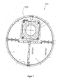
- FIG. 7 shows an insert 700 with blower 702 for insertion into a receiving pin 600 according to FIG. 6 or 11 according to FIG. 2 ,
- This insert 700 with blower 702 is also in the FIG. 2 shown in the inserted state.
- the fan 702 can thus blow the air into the interior 622 of the receiving pin 600.
- the insert 700 is otherwise configured so that the inner space 622 of the receiving pin 600 is closed, so that only by means of the blower 702 air can be blown into the inner space 622. As a result, a backward directed leakage of injected air from the interior 602 is avoided.
- the insert 700 thus has the task of carrying the blower 702 and at the same time completing the interior 622 of the receiving pin 600.
- the rotor hub 800 has sheet receptacles 802 for fastening a respective rotor blade. The rotor blade can then be rotated by means of pitch drives in its angle of attack.
- a pitch motor receptacle 804 for receiving the pitch drives is provided on each sheet receiver.
- the rotor hub 800 has two Rotorbefest Trentsflansche 806 for kipppfesten connection with the electric rotor, so rotor, the generator.
- the rotor hub 800 is intended to be rotatably mounted on a journal. As a result, the electric rotor attached to the rotor hub 800 is also rotatably supported.
- FIG. 9 shows the center axis 808 of the rotor hub 800 and thus the axis of rotation of the aerodynamic and thus simultaneously electric rotor.
- the arrangement of the rotor hub 800 on a journal is in the side sectional view of FIG. 2 shown.
- the rotor hub 9 is rotatably supported by means of a double-row tapered roller bearing 8 and a cylindrical roller bearing 12 on the journal 10.
- the attachment of the disc rotor to the rotor hub 9 can be seen in the sectional view.
- an axis 100 in the FIG. 2 drawn, which forms a rotation axis and center axis for various elements.
- a module carrier 810 is provided.
- the module carrier 810 is fastened to the rotor hub 800 by means of fastening struts 812. Also, the module carrier 810 is arranged substantially concentrically about the center axis 808. On the module carrier 810 various electric modules 814 are attached. In this case, the electric modules 814 point from the module carrier 810 in the direction of the rotor hub 800.
- a slip ring body namely the cup ring body 5 according to FIG. 2
- module carrier 810 protrudes a slip ring body, namely the cup ring body 5 according to FIG. 2 , through the module carrier 810 in the middle into the free area.
- auxiliary sheets 816 are provided on which service personnel can stand and work. Between the two auxiliary sheets 816, a recess 818 is shown. This can be used for service personnel to pass through and as a working space when mounting and dismounting the slip ring body 5. In particular, the slip ring body can be lowered during disassembly in this recess.
- the spinner cap 40 in the FIG. 2 is shown, elastic connecting means 820 are distributed in pairs over the module carrier 810.
- the arrangement of the slip ring body 5, the module carrier 810 and the spinner cap 40 is in the FIG. 2 indicated.
- the modules for supplying the pitch drives can be provided in a simple manner. A previously known positioning of such E-modules on the disc rotor can be improved thereby.
- the FIG. 12 shows a machine carrier 300, which is arranged above a tower 110. Attached to and substantially around the machine frame 300 is the nacelle structure 200.
- the nacelle structure 200 includes a base stage section 202 that is rigidly secured to the machine frame 300, particularly at the receiving portions 306 thereof.
- a support structure 204 is arranged, which has a plurality of vertical support struts 206 and horizontal support struts 208. This creates a stable support structure 204, which basically rebuilds the machine frame 300.
- this support structure also forms an upper work platform on which service personnel can stand and work and can be arranged on the electric modules 212, such as, for example, a rectifier or other control cabinets.
- an intermediate stage 214 is provided. Like from the FIG. 13 to recognize, is provided on each side of the machine frame 300 such an intermediate stage. Below this intermediate stage 214 azimuth motors 216 and azimuth drives 216 are arranged. From the intermediate stage 214, access to the azimuth drives 16 can thus be achieved by releasable bottom plates.
- a projecting support portion 218 is also arranged substantially in the form of a steel beam. This projecting support section 218 is additionally held on the support structure 204 via first and second support rods 220 and 222.
- the projecting support section 218 fulfills at least two tasks, namely a crane device 224 is provided to handle loads and possibly also to lift from outside into the nacelle. Accordingly, also in the FIG. 2 a load opening 125 below the crane, which carries there the reference numeral 29, provided.
- the projecting supporting portion 218 serves to support a suspended platform section 226 by means of two third holding bars 228.
- the suspended platform section 226 is furthermore fastened in a connection region 230 to the base stage section 202.
- the attachment at the connection region 230 is not rigid.
- this suspended platform section 226 provides this in a simple manner.
- any electronic leads may be routed in the suspended section or suspended platform section 226.
- FIG. 13 also shows an entry ladder 232, which extends from the tower to the gondola.
- This entry ladder 232 thus also shows a path from the tower to the nacelle through the manhole 234, and the entry way thus leads through the first tubular section 301 and outwardly past the second tubular section 302.
- a described intermediate stage 214 is provided above the azimuth motors. This embodiment is also favorable when dispensing with an upper stage above the machine carrier.
- the gondola 110 of the FIG. 14 has a fixed nacelle cover 112 and a spinner 114 with spinner panel 116 and a spinner 118 on.
- a fixed nacelle cover 112 for the sake of simplicity, no rotor blades are shown, but only their receptacle 120, as well as a fixed rotor blade extension 122. Further, heat sink 124 are shown.
- FIG. 14 is still an obstacle lights 126, a measuring mast 128 and also schematically a passive rear cooler 31 indicated.
- two air openings 130 are shown in the fixed nacelle cover 112. These air openings 130 have droplet separators, so that through these air openings 130 air can flow into the nacelle and any moisture present as droplets is removed.
- at least one of these droplet separators of the air openings 130 can be heated in order to prevent freezing of the droplet separator and thus closing of the air openings 130 at cold outside temperatures. Since only a reduced cooling requirement exists at low outside temperatures, it may be sufficient to provide only a part of the air openings 130 with such a heating device.
- the diameter of the generator in particular of the stator ring 19 and stator core 20, is significantly smaller than the diameter of the nacelle cover of the nacelle in this area.
- Embodiment 1 Module carrier for fixing electrical, for controlling one or more pitch drives of a wind turbine modules provided on a rotor hub of the wind turbine, with a base body for supporting the electrical modules, wherein the rotor hub is prepared to rotate about a substantially horizontal rotor axis, and the base body is prepared to be fixed in the axial direction of the rotor axis in front of the rotor hub.
- Embodiment 2 Module Carrier According to Embodiment 1 characterized in that the support body is substantially formed as an annular disc and / or is arranged perpendicular to the rotor axis.
- Embodiment 3 Module carrier according to embodiment 1 or 2 characterized in that the carrier body has a circumference adapted to a spinner casing and / or has fastening means for elastic connection to the spinner casing.
- Embodiment 5 rotor hub of a wind energy plant with a module carrier according to one of the preceding embodiments, wherein the module carrier is arranged by means of holding devices rigidly on the rotor hub on its side facing the wind and / or wherein the module carrier is arranged with its base body substantially perpendicular to the rotor axis and / / or wherein the module carrier is elastically connected to a spinner cover.
- Embodiment 6 nacelle construction of a nacelle of a wind turbine for carrying at least part of a nacelle cover, supporting technical equipment in the nacelle and / or supporting persons in the nacelle, comprising a base stage section rigidly attached to a machine frame and a base and / or Hanging platform section suspended from the base stage section.
- Embodiment 7 Gondola construction according to Embodiment 6, wherein a support structure is arranged and fixed on the base stage section, and the support structure has a projecting support section with a crane device for lifting loads and / or with a tension member connected to the suspended platform section for partially holding, in particular partially suspending the suspended platform section on the support section, the support structure carries an upper stage, in particular above the machine carrier, and carries below the upper stage and above the base stage section an intermediate stage, in particular above arranged in the machine carrier azimuth drives, wherein the intermediate stage has at least one movable bottom plate to access the azimuth drives through the intermediate stage create and / or on the machine frame and / or on the support structure a chip ring for supporting and / or stiffening a nacelle cover or a part thereof is attached.
- Embodiment 8 Gondola of a wind energy plant, in particular a gearless wind power plant, for recording the operation of the wind turbine required technical equipment, comprising a nacelle cover to protect the technical equipment from the weather and Ventilation openings in the nacelle cover for the admission of outside air for aerating the nacelle and / or for cooling the wind turbine or parts thereof, wherein the vents have droplets to separate moisture of incoming air.
- Embodiment 9 Gondola according to embodiment 8, comprising a nacelle construction according to embodiment 6 or 7, one or the chip ring for supporting and / or stiffening the nacelle cover or a part thereof, a module carrier according to any one of embodiments 1 to 4, a rotor hub according to Embodiment 5, a machine carrier according to one of the embodiments described above, a generator support structure according to one of the embodiments described above and / or a spigot according to one of the embodiments described above.
- Embodiment 10 Wind energy plant, in particular gearless wind energy plant, comprising a nacelle according to embodiment 8 or 9, a nacelle construction according to embodiment 6 or 7, one or the chip ring for supporting and / or stiffening the nacelle cover or a part thereof, a module carrier according to any one of embodiments 1 to 4, a rotor hub according to Embodiment 5, a machine carrier according to one of the embodiments described above, a generator construction according to one of the embodiments described above and / or a spigot according to one of the embodiments described above and / or wherein in a transition region between the nacelle cover and tower a seal against air passage of outside air is provided and / or the tower is sealed in the interior against air passage of air from the tower interior.
- a transition region between the nacelle cover and tower a seal against air passage of outside air is provided and / or the tower is sealed in the interior against air passage of air from the tower interior.
- Embodiment 11 Method for Erecting a Wind Energy Plant, wherein a module carrier, in particular a module carrier according to one of embodiments 1-4, is prefabricated with electrical modules provided for controlling one or more pitch drives of a wind energy plant and equipped with the modules and on a rotor hub the wind turbine is attached, thereby securing the modules in one step to the rotor hub.
- a module carrier in particular a module carrier according to one of embodiments 1-4, is prefabricated with electrical modules provided for controlling one or more pitch drives of a wind energy plant and equipped with the modules and on a rotor hub the wind turbine is attached, thereby securing the modules in one step to the rotor hub.
- Embodiment 13 A method according to Embodiment 11 or 12, wherein a wind turbine according to Embodiment 10 is erected.
- Embodiment 14 Method for Operating a Wind Turbine, wherein a fan blows cooling air from a first part of a nacelle into a second part of the nacelle, in particular into a region of a rotor hub and / or rotor head, through a mounting pin and / or journal, the cooling air passes completely or partially through at least one droplet separator in a nacelle cover in the first part of the nacelle and the cooling air wholly or partially in the region of the rotor hub in a transition region between a spinner panel and the nacelle panel exits the nacelle.
Landscapes
- Engineering & Computer Science (AREA)
- Life Sciences & Earth Sciences (AREA)
- Sustainable Development (AREA)
- Sustainable Energy (AREA)
- Chemical & Material Sciences (AREA)
- Combustion & Propulsion (AREA)
- Mechanical Engineering (AREA)
- General Engineering & Computer Science (AREA)
- Physics & Mathematics (AREA)
- Fluid Mechanics (AREA)
- Power Engineering (AREA)
- Wind Motors (AREA)
Applications Claiming Priority (2)
| Application Number | Priority Date | Filing Date | Title |
|---|---|---|---|
| DE102010043435A DE102010043435A1 (de) | 2010-11-04 | 2010-11-04 | Windenergieanlage |
| EP11778644.2A EP2635804B1 (fr) | 2010-11-04 | 2011-11-04 | Éolienne |
Related Parent Applications (2)
| Application Number | Title | Priority Date | Filing Date |
|---|---|---|---|
| EP11778644.2A Division-Into EP2635804B1 (fr) | 2010-11-04 | 2011-11-04 | Éolienne |
| EP11778644.2A Division EP2635804B1 (fr) | 2010-11-04 | 2011-11-04 | Éolienne |
Publications (2)
| Publication Number | Publication Date |
|---|---|
| EP2806157A1 true EP2806157A1 (fr) | 2014-11-26 |
| EP2806157B1 EP2806157B1 (fr) | 2017-09-06 |
Family
ID=44906165
Family Applications (2)
| Application Number | Title | Priority Date | Filing Date |
|---|---|---|---|
| EP11778644.2A Active EP2635804B1 (fr) | 2010-11-04 | 2011-11-04 | Éolienne |
| EP14175560.3A Active EP2806157B1 (fr) | 2010-11-04 | 2011-11-04 | Éolienne |
Family Applications Before (1)
| Application Number | Title | Priority Date | Filing Date |
|---|---|---|---|
| EP11778644.2A Active EP2635804B1 (fr) | 2010-11-04 | 2011-11-04 | Éolienne |
Country Status (20)
| Country | Link |
|---|---|
| US (1) | US9316204B2 (fr) |
| EP (2) | EP2635804B1 (fr) |
| JP (1) | JP5758007B2 (fr) |
| KR (1) | KR101516902B1 (fr) |
| CN (1) | CN103249944B (fr) |
| AR (1) | AR084135A1 (fr) |
| AU (1) | AU2011325127B2 (fr) |
| BR (1) | BR112013010734A2 (fr) |
| CA (1) | CA2814994C (fr) |
| CL (1) | CL2013001173A1 (fr) |
| DE (1) | DE102010043435A1 (fr) |
| DK (2) | DK2635804T3 (fr) |
| ES (2) | ES2732923T3 (fr) |
| MX (1) | MX339931B (fr) |
| NZ (1) | NZ610235A (fr) |
| PT (2) | PT2806157T (fr) |
| RU (1) | RU2564734C2 (fr) |
| TW (1) | TWI526610B (fr) |
| WO (1) | WO2012059591A2 (fr) |
| ZA (1) | ZA201302783B (fr) |
Families Citing this family (20)
| Publication number | Priority date | Publication date | Assignee | Title |
|---|---|---|---|---|
| ES2675724T3 (es) * | 2011-12-21 | 2018-07-12 | Wobben Properties Gmbh | Góndola de planta de energía eólica |
| EP2620644B1 (fr) | 2012-01-30 | 2015-06-17 | Siemens Aktiengesellschaft | Améliorations portant sur un ensemble d'éolienne |
| DK2685098T3 (en) * | 2012-07-10 | 2015-05-04 | Siemens Ag | Base frame structure for a wind turbine |
| CN103233855B (zh) * | 2013-02-26 | 2015-10-07 | 北京三力新能科技有限公司 | 风力叶轮混合桨距技术 |
| DK2806542T3 (en) | 2013-05-22 | 2016-12-19 | Siemens Ag | Airflow Control Device |
| KR101435375B1 (ko) * | 2013-08-23 | 2014-08-29 | 삼성중공업 주식회사 | 풍력발전기의 스피너 커버 조립용 지그와 이를 이용한 스피너 커버의 조립방법 |
| DK178005B1 (en) * | 2013-10-11 | 2015-03-02 | Envision Energy Denmark Aps | Wind Rotor Brake System |
| US9325224B2 (en) * | 2013-12-28 | 2016-04-26 | Google Inc. | Electrically-isolated and liquid-cooled rotor and stator assemblies |
| DK2924281T3 (en) * | 2014-03-25 | 2018-12-10 | Siemens Ag | Support structure of a wind turbine |
| DE102014206703A1 (de) * | 2014-04-07 | 2015-10-08 | Wobben Properties Gmbh | Gondel einer Windenergieanlage |
| CN106164485B (zh) * | 2014-04-07 | 2020-08-07 | 乌本产权有限公司 | 风力涡轮机的吊舱 |
| CN107131097B (zh) * | 2016-02-29 | 2021-03-23 | 通用电气公司 | 用于风轮机转子毂的内部阶梯组件 |
| DE102016206179A1 (de) * | 2016-04-13 | 2017-10-19 | Wobben Properties Gmbh | Generatorrotor für einen Generator einer Windenergieanlage oder eines Wasserkraftwerks, sowie Generator, Windenergieanlage und Wasserkraftwerk mit selbigem |
| EP3242013A1 (fr) | 2016-05-04 | 2017-11-08 | Nordex Energy GmbH | Éolienne comprenant un dispositif destine a faire tourner une nacelle de l'eolienne et procede de montage d'un dispositif destine a faire tourner une nacelle |
| EP3263892A1 (fr) * | 2016-07-01 | 2018-01-03 | Siemens Aktiengesellschaft | Éolienne pourvue d'un capteur de vent |
| DE102016124016A1 (de) | 2016-12-12 | 2018-06-14 | Wobben Properties Gmbh | Windenergieanlage und Verfahren zum Absaugen von Rauch in einer Windenergieanlage |
| DE102018102428A1 (de) * | 2018-02-02 | 2019-08-08 | Wobben Properties Gmbh | Gondel einer Windenergieanlage, sowie Windenergieanlage mit Gondel und Verfahren zur Wartung einer solchen Windenergieanlage |
| DE102018108610A1 (de) | 2018-04-11 | 2019-10-17 | Wobben Properties Gmbh | Rotornabe einer Windenergieanlage, sowie Verfahren zur Montage einer solchen Rotornabe |
| DE102018131321A1 (de) * | 2018-12-07 | 2020-06-10 | Wobben Properties Gmbh | Windenergieanlage mit Tragstruktur |
| KR102193215B1 (ko) | 2019-08-23 | 2020-12-18 | 두산중공업 주식회사 | 풍력 발전장치 |
Citations (5)
| Publication number | Priority date | Publication date | Assignee | Title |
|---|---|---|---|---|
| DE10102255A1 (de) * | 2001-01-19 | 2002-08-01 | Aloys Wobben | Windenergieanlage mit einer Hohlwelle für Rotornabe und Generator |
| EP1319830A1 (fr) * | 1999-10-18 | 2003-06-18 | Manuel Torres Martinez | Aerogenerateur multipolaire |
| EP1394406A2 (fr) * | 2002-08-28 | 2004-03-03 | Friedrich Prof. Dr.-Ing. Klinger | Eolienne sans multiplicateur avec générateur multipolaire |
| EP2194269A1 (fr) * | 2007-10-05 | 2010-06-09 | Mitsubishi Heavy Industries, Ltd. | Générateur électrique éolien |
| DE102009008437A1 (de) * | 2009-02-11 | 2010-08-12 | Vensys Energy Ag | Maschinenträger zur Aufnahme einer Rotor-/ Generatorbaugruppe einer getriebelosen Windenenergieanlage |
Family Cites Families (21)
| Publication number | Priority date | Publication date | Assignee | Title |
|---|---|---|---|---|
| FR2760492B1 (fr) | 1997-03-10 | 2001-11-09 | Jeumont Ind | Systeme de production d'energie electrique associe a une eolienne |
| DE19916454A1 (de) * | 1999-04-12 | 2000-10-19 | Flender A F & Co | Getriebe für eine Windkraftanlage |
| JP2001099045A (ja) * | 1999-10-01 | 2001-04-10 | Mitsubishi Heavy Ind Ltd | 風車のブレードピッチ可変機構 |
| ITBZ20010043A1 (it) * | 2001-09-13 | 2003-03-13 | High Technology Invest Bv | Generatore elettrico azionato da energia eolica. |
| DE10224439C5 (de) * | 2002-06-01 | 2009-12-31 | Aloys Wobben | Verfahren zur Montage/Demontage von Komponenten einer Windenergieanlage |
| US7160083B2 (en) | 2003-02-03 | 2007-01-09 | General Electric Company | Method and apparatus for wind turbine rotor load control |
| DE102004064007B4 (de) * | 2004-09-24 | 2009-08-20 | Aloys Wobben | Windenergieanlage mit einer Generatorkühlung |
| US7427814B2 (en) * | 2006-03-22 | 2008-09-23 | General Electric Company | Wind turbine generators having wind assisted cooling systems and cooling methods |
| ES2373791T5 (es) * | 2007-02-12 | 2017-12-27 | Vestas Wind Systems A/S | Turbina eólica y procedimiento para establecer al menos una abertura en la contera sobre el buje de un rotor de turbina eólica |
| DE102007012408A1 (de) * | 2007-03-15 | 2008-09-18 | Aerodyn Engineering Gmbh | Windenergieanlagen mit lastübertragenden Bauteilen |
| FR2929345B1 (fr) * | 2008-03-26 | 2017-06-23 | Tecddis | Dispositif de roulement pour nacelle d'eolienne |
| WO2009156243A2 (fr) * | 2008-06-24 | 2009-12-30 | Vestas Wind Systems A/S | Enveloppe de moyeu pour le moyeu d'une éolienne |
| DE102008038740A1 (de) * | 2008-08-12 | 2010-02-18 | Nordex Energy Gmbh | Windenergieanlage sowie Verfahren zum Beheizen von in der Rotornabe einer Windenergieanlage angeordneten Energiespeichern |
| US8070446B2 (en) * | 2008-09-10 | 2011-12-06 | Moog Japan Ltd. | Wind turbine blade pitch control system |
| DE102009005516A1 (de) * | 2009-01-20 | 2010-07-22 | Repower Systems Ag | Motorbelastungsreduktion bei einer Windenenergieanlage |
| IT1393937B1 (it) * | 2009-04-09 | 2012-05-17 | Rolic Invest Sarl | Aerogeneratore |
| DE102009017865A1 (de) * | 2009-04-17 | 2010-10-28 | Schuler Pressen Gmbh & Co. Kg | Generatoranordnung für Windenergieanlage |
| CA2698710A1 (fr) * | 2009-05-05 | 2010-11-05 | Fws Technologies Holdings Ltd. | Tour d'eolienne en beton faconne par coffrages glissants |
| WO2011004482A1 (fr) | 2009-07-09 | 2011-01-13 | 三菱重工業株式会社 | Générateur dénergie éolienne |
| KR101424099B1 (ko) | 2009-11-17 | 2014-07-31 | 에스에스비 윈드 시스템즈 게엠베하 운트 코 카게 | 풍력 터빈용 제어 캐비닛 |
| DE102009044570A1 (de) | 2009-11-17 | 2011-05-19 | Ssb Wind Systems Gmbh & Co. Kg | Windkraftanlage |
-
2010
- 2010-11-04 DE DE102010043435A patent/DE102010043435A1/de not_active Withdrawn
-
2011
- 2011-11-03 TW TW100140193A patent/TWI526610B/zh not_active IP Right Cessation
- 2011-11-04 RU RU2013125582/06A patent/RU2564734C2/ru not_active IP Right Cessation
- 2011-11-04 MX MX2013004962A patent/MX339931B/es active IP Right Grant
- 2011-11-04 DK DK11778644.2T patent/DK2635804T3/da active
- 2011-11-04 AU AU2011325127A patent/AU2011325127B2/en not_active Ceased
- 2011-11-04 EP EP11778644.2A patent/EP2635804B1/fr active Active
- 2011-11-04 ES ES11778644T patent/ES2732923T3/es active Active
- 2011-11-04 US US13/883,453 patent/US9316204B2/en active Active
- 2011-11-04 JP JP2013537153A patent/JP5758007B2/ja not_active Expired - Fee Related
- 2011-11-04 AR ARP110104102A patent/AR084135A1/es active IP Right Grant
- 2011-11-04 ES ES14175560.3T patent/ES2649720T3/es active Active
- 2011-11-04 NZ NZ610235A patent/NZ610235A/en not_active IP Right Cessation
- 2011-11-04 PT PT141755603T patent/PT2806157T/pt unknown
- 2011-11-04 KR KR1020137014406A patent/KR101516902B1/ko active IP Right Grant
- 2011-11-04 BR BR112013010734A patent/BR112013010734A2/pt active Search and Examination
- 2011-11-04 EP EP14175560.3A patent/EP2806157B1/fr active Active
- 2011-11-04 PT PT11778644T patent/PT2635804T/pt unknown
- 2011-11-04 DK DK14175560.3T patent/DK2806157T3/en active
- 2011-11-04 CN CN201180053473.2A patent/CN103249944B/zh active Active
- 2011-11-04 CA CA2814994A patent/CA2814994C/fr not_active Expired - Fee Related
- 2011-11-04 WO PCT/EP2011/069459 patent/WO2012059591A2/fr active Application Filing
-
2013
- 2013-04-18 ZA ZA2013/02783A patent/ZA201302783B/en unknown
- 2013-04-29 CL CL2013001173A patent/CL2013001173A1/es unknown
Patent Citations (5)
| Publication number | Priority date | Publication date | Assignee | Title |
|---|---|---|---|---|
| EP1319830A1 (fr) * | 1999-10-18 | 2003-06-18 | Manuel Torres Martinez | Aerogenerateur multipolaire |
| DE10102255A1 (de) * | 2001-01-19 | 2002-08-01 | Aloys Wobben | Windenergieanlage mit einer Hohlwelle für Rotornabe und Generator |
| EP1394406A2 (fr) * | 2002-08-28 | 2004-03-03 | Friedrich Prof. Dr.-Ing. Klinger | Eolienne sans multiplicateur avec générateur multipolaire |
| EP2194269A1 (fr) * | 2007-10-05 | 2010-06-09 | Mitsubishi Heavy Industries, Ltd. | Générateur électrique éolien |
| DE102009008437A1 (de) * | 2009-02-11 | 2010-08-12 | Vensys Energy Ag | Maschinenträger zur Aufnahme einer Rotor-/ Generatorbaugruppe einer getriebelosen Windenenergieanlage |
Also Published As
Similar Documents
| Publication | Publication Date | Title |
|---|---|---|
| EP2806157B1 (fr) | Éolienne | |
| EP2795108B1 (fr) | Nacelle d'éolienne | |
| DE10362212B4 (de) | 4Windenergieanlage und Lageranordnung dafür | |
| EP2917572B1 (fr) | Éolienne | |
| EP3129651B1 (fr) | Nacelle pour éolienne | |
| US10781798B2 (en) | Nacelle component for a wind turbine and method for mounting a nacelle component | |
| EP3276169A1 (fr) | Éolienne | |
| WO2012003985A1 (fr) | Éolienne et procédé de réglage de l'axe de rotation du rotor | |
| DE4402184A1 (de) | Vielpol-Synchrongenerator für getriebelose Horizontalachsen-Windkraftanlagen mit Nennleistungen bis zu mehreren Megawatt | |
| EP2351191A2 (fr) | Générateur annulaire | |
| EP3317952B1 (fr) | Élément de support, en particulier élément de support d'un stator et/ou d'un rotor, system des éléments de support, support de générateur, générateur, système de support de générateur, nacelle d'une éolienne, éolienne et procédé de montage d'un système de support de générateur | |
| EP2140136B1 (fr) | Éolienne | |
| DE102009007812B4 (de) | Windkraftanlage mit windschlüpfiger Profilierung | |
| DE102018113760B4 (de) | Rotorlagergehäuse und Windenergieanlage mit Rotorlagergehäuse | |
| CN110566418B (zh) | 旋转连接结构及风力发电机组 | |
| EP2920456B1 (fr) | Système de turbines éoliennes équipé d'une console de tour | |
| DE102011089431A1 (de) | Windenergieanlagengondel | |
| US20230072624A1 (en) | Wind turbine nacelles | |
| WO2023208345A1 (fr) | Système de conversion d'énergie d'écoulement d'air sous forme d'intégration d'accessoire dans des centrales solaires pour une alimentation supplémentaire en énergie électrique | |
| WO2024055053A1 (fr) | Panneau servant de convertisseur d'énergie éolienne et son utilisation |
Legal Events
| Date | Code | Title | Description |
|---|---|---|---|
| PUAI | Public reference made under article 153(3) epc to a published international application that has entered the european phase |
Free format text: ORIGINAL CODE: 0009012 |
|
| 17P | Request for examination filed |
Effective date: 20140703 |
|
| AC | Divisional application: reference to earlier application |
Ref document number: 2635804 Country of ref document: EP Kind code of ref document: P |
|
| AK | Designated contracting states |
Kind code of ref document: A1 Designated state(s): AL AT BE BG CH CY CZ DE DK EE ES FI FR GB GR HR HU IE IS IT LI LT LU LV MC MK MT NL NO PL PT RO RS SE SI SK SM TR |
|
| AX | Request for extension of the european patent |
Extension state: BA |
|
| R17P | Request for examination filed (corrected) |
Effective date: 20150526 |
|
| RAX | Requested extension states of the european patent have changed |
Extension state: BA Payment date: 20150526 |
|
| RBV | Designated contracting states (corrected) |
Designated state(s): AL AT BE BG CH CY CZ DE DK EE ES FI FR GB GR HR HU IE IS IT LI LT LU LV MC MK MT NL NO PL PT RO RS SE SI SK SM TR |
|
| RAP1 | Party data changed (applicant data changed or rights of an application transferred) |
Owner name: WOBBEN PROPERTIES GMBH |
|
| 17Q | First examination report despatched |
Effective date: 20160407 |
|
| REG | Reference to a national code |
Ref country code: DE Ref legal event code: R079 Ref document number: 502011012973 Country of ref document: DE Free format text: PREVIOUS MAIN CLASS: F03D0001000000 Ipc: F03D0080000000 |
|
| RIC1 | Information provided on ipc code assigned before grant |
Ipc: F03D 13/10 20160101ALI20170321BHEP Ipc: F03D 13/20 20160101ALI20170321BHEP Ipc: F03D 1/06 20060101ALI20170321BHEP Ipc: F03D 80/00 20160101AFI20170321BHEP Ipc: F03D 80/80 20160101ALI20170321BHEP Ipc: F03D 15/20 20160101ALI20170321BHEP Ipc: F03D 80/50 20160101ALI20170321BHEP |
|
| GRAP | Despatch of communication of intention to grant a patent |
Free format text: ORIGINAL CODE: EPIDOSNIGR1 |
|
| INTG | Intention to grant announced |
Effective date: 20170509 |
|
| GRAS | Grant fee paid |
Free format text: ORIGINAL CODE: EPIDOSNIGR3 |
|
| GRAA | (expected) grant |
Free format text: ORIGINAL CODE: 0009210 |
|
| AC | Divisional application: reference to earlier application |
Ref document number: 2635804 Country of ref document: EP Kind code of ref document: P |
|
| AK | Designated contracting states |
Kind code of ref document: B1 Designated state(s): AL AT BE BG CH CY CZ DE DK EE ES FI FR GB GR HR HU IE IS IT LI LT LU LV MC MK MT NL NO PL PT RO RS SE SI SK SM TR |
|
| AX | Request for extension of the european patent |
Extension state: BA |
|
| REG | Reference to a national code |
Ref country code: GB Ref legal event code: FG4D Free format text: NOT ENGLISH |
|
| RIN1 | Information on inventor provided before grant (corrected) |
Inventor name: ROEER, JOCHEN Inventor name: FRICKE, WERNER Inventor name: HILDEBRAND, ARNO Inventor name: BAUMGAERTEL, CHRISTIAN Inventor name: GEIKEN, PETER Inventor name: SARTORIUS, FLORIAN Inventor name: GUDEWER, WILKO |
|
| REG | Reference to a national code |
Ref country code: CH Ref legal event code: EP Ref country code: AT Ref legal event code: REF Ref document number: 926194 Country of ref document: AT Kind code of ref document: T Effective date: 20170915 |
|
| REG | Reference to a national code |
Ref country code: IE Ref legal event code: FG4D Free format text: LANGUAGE OF EP DOCUMENT: GERMAN |
|
| REG | Reference to a national code |
Ref country code: DE Ref legal event code: R096 Ref document number: 502011012973 Country of ref document: DE |
|
| REG | Reference to a national code |
Ref country code: DK Ref legal event code: T3 Effective date: 20171023 |
|
| REG | Reference to a national code |
Ref country code: FR Ref legal event code: PLFP Year of fee payment: 7 |
|
| REG | Reference to a national code |
Ref country code: PT Ref legal event code: SC4A Ref document number: 2806157 Country of ref document: PT Date of ref document: 20171201 Kind code of ref document: T Free format text: AVAILABILITY OF NATIONAL TRANSLATION Effective date: 20171124 |
|
| REG | Reference to a national code |
Ref country code: SE Ref legal event code: TRGR |
|
| REG | Reference to a national code |
Ref country code: NL Ref legal event code: FP |
|
| REG | Reference to a national code |
Ref country code: ES Ref legal event code: FG2A Ref document number: 2649720 Country of ref document: ES Kind code of ref document: T3 Effective date: 20180115 |
|
| REG | Reference to a national code |
Ref country code: LT Ref legal event code: MG4D |
|
| PG25 | Lapsed in a contracting state [announced via postgrant information from national office to epo] |
Ref country code: HR Free format text: LAPSE BECAUSE OF FAILURE TO SUBMIT A TRANSLATION OF THE DESCRIPTION OR TO PAY THE FEE WITHIN THE PRESCRIBED TIME-LIMIT Effective date: 20170906 Ref country code: LT Free format text: LAPSE BECAUSE OF FAILURE TO SUBMIT A TRANSLATION OF THE DESCRIPTION OR TO PAY THE FEE WITHIN THE PRESCRIBED TIME-LIMIT Effective date: 20170906 Ref country code: FI Free format text: LAPSE BECAUSE OF FAILURE TO SUBMIT A TRANSLATION OF THE DESCRIPTION OR TO PAY THE FEE WITHIN THE PRESCRIBED TIME-LIMIT Effective date: 20170906 Ref country code: NO Free format text: LAPSE BECAUSE OF FAILURE TO SUBMIT A TRANSLATION OF THE DESCRIPTION OR TO PAY THE FEE WITHIN THE PRESCRIBED TIME-LIMIT Effective date: 20171206 |
|
| PG25 | Lapsed in a contracting state [announced via postgrant information from national office to epo] |
Ref country code: BG Free format text: LAPSE BECAUSE OF FAILURE TO SUBMIT A TRANSLATION OF THE DESCRIPTION OR TO PAY THE FEE WITHIN THE PRESCRIBED TIME-LIMIT Effective date: 20171206 Ref country code: LV Free format text: LAPSE BECAUSE OF FAILURE TO SUBMIT A TRANSLATION OF THE DESCRIPTION OR TO PAY THE FEE WITHIN THE PRESCRIBED TIME-LIMIT Effective date: 20170906 Ref country code: RS Free format text: LAPSE BECAUSE OF FAILURE TO SUBMIT A TRANSLATION OF THE DESCRIPTION OR TO PAY THE FEE WITHIN THE PRESCRIBED TIME-LIMIT Effective date: 20170906 |
|
| REG | Reference to a national code |
Ref country code: GR Ref legal event code: EP Ref document number: 20170403026 Country of ref document: GR Effective date: 20180330 |
|
| PG25 | Lapsed in a contracting state [announced via postgrant information from national office to epo] |
Ref country code: CZ Free format text: LAPSE BECAUSE OF FAILURE TO SUBMIT A TRANSLATION OF THE DESCRIPTION OR TO PAY THE FEE WITHIN THE PRESCRIBED TIME-LIMIT Effective date: 20170906 Ref country code: RO Free format text: LAPSE BECAUSE OF FAILURE TO SUBMIT A TRANSLATION OF THE DESCRIPTION OR TO PAY THE FEE WITHIN THE PRESCRIBED TIME-LIMIT Effective date: 20170906 Ref country code: PL Free format text: LAPSE BECAUSE OF FAILURE TO SUBMIT A TRANSLATION OF THE DESCRIPTION OR TO PAY THE FEE WITHIN THE PRESCRIBED TIME-LIMIT Effective date: 20170906 |
|
| PG25 | Lapsed in a contracting state [announced via postgrant information from national office to epo] |
Ref country code: SK Free format text: LAPSE BECAUSE OF FAILURE TO SUBMIT A TRANSLATION OF THE DESCRIPTION OR TO PAY THE FEE WITHIN THE PRESCRIBED TIME-LIMIT Effective date: 20170906 Ref country code: IS Free format text: LAPSE BECAUSE OF FAILURE TO SUBMIT A TRANSLATION OF THE DESCRIPTION OR TO PAY THE FEE WITHIN THE PRESCRIBED TIME-LIMIT Effective date: 20180106 Ref country code: IT Free format text: LAPSE BECAUSE OF FAILURE TO SUBMIT A TRANSLATION OF THE DESCRIPTION OR TO PAY THE FEE WITHIN THE PRESCRIBED TIME-LIMIT Effective date: 20170906 Ref country code: SM Free format text: LAPSE BECAUSE OF FAILURE TO SUBMIT A TRANSLATION OF THE DESCRIPTION OR TO PAY THE FEE WITHIN THE PRESCRIBED TIME-LIMIT Effective date: 20170906 Ref country code: EE Free format text: LAPSE BECAUSE OF FAILURE TO SUBMIT A TRANSLATION OF THE DESCRIPTION OR TO PAY THE FEE WITHIN THE PRESCRIBED TIME-LIMIT Effective date: 20170906 |
|
| REG | Reference to a national code |
Ref country code: DE Ref legal event code: R097 Ref document number: 502011012973 Country of ref document: DE |
|
| PG25 | Lapsed in a contracting state [announced via postgrant information from national office to epo] |
Ref country code: MC Free format text: LAPSE BECAUSE OF FAILURE TO SUBMIT A TRANSLATION OF THE DESCRIPTION OR TO PAY THE FEE WITHIN THE PRESCRIBED TIME-LIMIT Effective date: 20170906 |
|
| PLBE | No opposition filed within time limit |
Free format text: ORIGINAL CODE: 0009261 |
|
| STAA | Information on the status of an ep patent application or granted ep patent |
Free format text: STATUS: NO OPPOSITION FILED WITHIN TIME LIMIT |
|
| PG25 | Lapsed in a contracting state [announced via postgrant information from national office to epo] |
Ref country code: LI Free format text: LAPSE BECAUSE OF NON-PAYMENT OF DUE FEES Effective date: 20171130 Ref country code: CH Free format text: LAPSE BECAUSE OF NON-PAYMENT OF DUE FEES Effective date: 20171130 |
|
| 26N | No opposition filed |
Effective date: 20180607 |
|
| PG25 | Lapsed in a contracting state [announced via postgrant information from national office to epo] |
Ref country code: SI Free format text: LAPSE BECAUSE OF FAILURE TO SUBMIT A TRANSLATION OF THE DESCRIPTION OR TO PAY THE FEE WITHIN THE PRESCRIBED TIME-LIMIT Effective date: 20170906 Ref country code: LU Free format text: LAPSE BECAUSE OF NON-PAYMENT OF DUE FEES Effective date: 20171104 |
|
| REG | Reference to a national code |
Ref country code: BE Ref legal event code: MM Effective date: 20171130 |
|
| REG | Reference to a national code |
Ref country code: IE Ref legal event code: MM4A |
|
| PG25 | Lapsed in a contracting state [announced via postgrant information from national office to epo] |
Ref country code: MT Free format text: LAPSE BECAUSE OF FAILURE TO SUBMIT A TRANSLATION OF THE DESCRIPTION OR TO PAY THE FEE WITHIN THE PRESCRIBED TIME-LIMIT Effective date: 20170906 |
|
| PG25 | Lapsed in a contracting state [announced via postgrant information from national office to epo] |
Ref country code: IE Free format text: LAPSE BECAUSE OF NON-PAYMENT OF DUE FEES Effective date: 20171104 |
|
| PG25 | Lapsed in a contracting state [announced via postgrant information from national office to epo] |
Ref country code: BE Free format text: LAPSE BECAUSE OF NON-PAYMENT OF DUE FEES Effective date: 20171130 |
|
| PG25 | Lapsed in a contracting state [announced via postgrant information from national office to epo] |
Ref country code: HU Free format text: LAPSE BECAUSE OF FAILURE TO SUBMIT A TRANSLATION OF THE DESCRIPTION OR TO PAY THE FEE WITHIN THE PRESCRIBED TIME-LIMIT; INVALID AB INITIO Effective date: 20111104 |
|
| PG25 | Lapsed in a contracting state [announced via postgrant information from national office to epo] |
Ref country code: CY Free format text: LAPSE BECAUSE OF FAILURE TO SUBMIT A TRANSLATION OF THE DESCRIPTION OR TO PAY THE FEE WITHIN THE PRESCRIBED TIME-LIMIT Effective date: 20170906 |
|
| PG25 | Lapsed in a contracting state [announced via postgrant information from national office to epo] |
Ref country code: MK Free format text: LAPSE BECAUSE OF FAILURE TO SUBMIT A TRANSLATION OF THE DESCRIPTION OR TO PAY THE FEE WITHIN THE PRESCRIBED TIME-LIMIT Effective date: 20170906 |
|
| PGFP | Annual fee paid to national office [announced via postgrant information from national office to epo] |
Ref country code: SE Payment date: 20191125 Year of fee payment: 9 Ref country code: PT Payment date: 20191028 Year of fee payment: 9 |
|
| PGFP | Annual fee paid to national office [announced via postgrant information from national office to epo] |
Ref country code: ES Payment date: 20191216 Year of fee payment: 9 Ref country code: GR Payment date: 20191120 Year of fee payment: 9 |
|
| PG25 | Lapsed in a contracting state [announced via postgrant information from national office to epo] |
Ref country code: TR Free format text: LAPSE BECAUSE OF FAILURE TO SUBMIT A TRANSLATION OF THE DESCRIPTION OR TO PAY THE FEE WITHIN THE PRESCRIBED TIME-LIMIT Effective date: 20170906 |
|
| PGFP | Annual fee paid to national office [announced via postgrant information from national office to epo] |
Ref country code: AT Payment date: 20191119 Year of fee payment: 9 |
|
| PG25 | Lapsed in a contracting state [announced via postgrant information from national office to epo] |
Ref country code: AL Free format text: LAPSE BECAUSE OF FAILURE TO SUBMIT A TRANSLATION OF THE DESCRIPTION OR TO PAY THE FEE WITHIN THE PRESCRIBED TIME-LIMIT Effective date: 20170906 |
|
| REG | Reference to a national code |
Ref country code: SE Ref legal event code: EUG |
|
| REG | Reference to a national code |
Ref country code: AT Ref legal event code: MM01 Ref document number: 926194 Country of ref document: AT Kind code of ref document: T Effective date: 20201104 |
|
| PG25 | Lapsed in a contracting state [announced via postgrant information from national office to epo] |
Ref country code: PT Free format text: LAPSE BECAUSE OF NON-PAYMENT OF DUE FEES Effective date: 20210504 Ref country code: GR Free format text: LAPSE BECAUSE OF NON-PAYMENT OF DUE FEES Effective date: 20210608 |
|
| PG25 | Lapsed in a contracting state [announced via postgrant information from national office to epo] |
Ref country code: SE Free format text: LAPSE BECAUSE OF NON-PAYMENT OF DUE FEES Effective date: 20201105 Ref country code: AT Free format text: LAPSE BECAUSE OF NON-PAYMENT OF DUE FEES Effective date: 20201104 |
|
| REG | Reference to a national code |
Ref country code: ES Ref legal event code: FD2A Effective date: 20220201 |
|
| PG25 | Lapsed in a contracting state [announced via postgrant information from national office to epo] |
Ref country code: ES Free format text: LAPSE BECAUSE OF NON-PAYMENT OF DUE FEES Effective date: 20201105 |
|
| PGFP | Annual fee paid to national office [announced via postgrant information from national office to epo] |
Ref country code: NL Payment date: 20231122 Year of fee payment: 13 |
|
| PGFP | Annual fee paid to national office [announced via postgrant information from national office to epo] |
Ref country code: GB Payment date: 20231123 Year of fee payment: 13 |
|
| PGFP | Annual fee paid to national office [announced via postgrant information from national office to epo] |
Ref country code: FR Payment date: 20231123 Year of fee payment: 13 Ref country code: DK Payment date: 20231122 Year of fee payment: 13 Ref country code: DE Payment date: 20231205 Year of fee payment: 13 |